Xylem Analytics Germany EBIIFXXX Data Logger Interfaces User Manual Seite1
Xylem Analytics Germany GmbH Data Logger Interfaces Seite1
Contents
- 1. Users manual
- 2. Users Manual
Users Manual
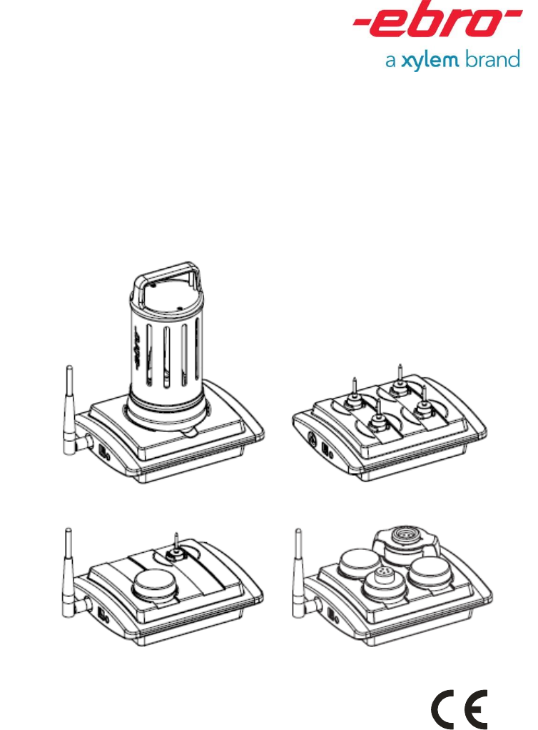
Interface
EBI IF-100/150//200/300

2
Deutsch
EBI IF-100/150/200/300
Inhaltsverzeichnis
Überblick 4
Sicherheitshinweise 6
Auspacken/Lieferumfang 8
Interface in Betrieb nehmen 10
Passende Antenne anschließen 12
Bei Bedarf: Netzteil anschließen 14
Bedeutung der Farbsignale 16
Interface-Betriebsarten (Modi) 18
Betrieb im Standard- Modus 20
Betrieb im Funkmodus 24
Was tun wenn… 28
...die Statusanzeigen dunkel bleiben? 28
...der PC „Interface nicht gefunden“ meldet?
28
...keine Verbindung zum Datenlogger
zustande kommt? 30
Reinigung und Pflege 32
Entsorgung 32
Elimination 33
Technische Daten 34
Zulassungen 34

1340-6001 1208 3
English
Français
Table of Contents
Overview 5
Safety Instructions 7
Unpacking/What is Included in the
Delivery 9
Operating the Interface 11
Connecting a suitable antenna 13
If required, connect a power supply unit
15
Meaning of the colored status display
lights 17
Interface operating types (modes) 19
Operation in wireless mode 25
What to do, if… 29
...the status display lights remain dark? 29
...the PC responds with “Interface not found”
29
...no connection is established to the data
logger? 31
Cleaning and Maintenance 33
Disposal 33
Technical Data 35
Approvals 35
Sommaire
Vue d’ensemble 5
Consignes de sécurité 7
Déballage / Fourniture 9
Mise en service de l’interface 11
Branchement de l’antenne adaptée 13
Au besoin : branchement d’une
alimentation secteur 15
Signification des signaux de couleur17
Modes d’exploitation de l’interface 19
Utilisation en mode standard 21
Utilisation en mode radio 25
Que faire quand… 29
...les indicateurs de statut ne s’allument pas
? 29
...l’ordinateur affi che le message « Interface
introuvable » ? 29
....il n’est pas possible d’établir la connexion
avec l’enregistreur de données ? 31
Nettoyage et entretien 33
Elimination 33
Caractéristiques techniques 35
Homologations 35
4
Deutsch
EBI IF-100/150/200/300
Überblick
Das Interface EBI IF-100/150/200/300 ist
ein Programmier- und Lesegerät der Serie
EBI 10/15/11 sowie ein Funkempfänger für
Datenlogger der Serie EBI 10.
Die Datenlogger EBI 10 werden per Funk
im Frequenzbereich 2,4 GHz programmiert
und ausgelesen.
Das Interface wird über ein Kabel mit einem
PC verbunden, von dort mit Hilfe einer
entsprechenden Software (z. B.
„Winlog.pro“) gesteuert und in der Regel
auch von dort mit Strom versorgt. Für den
Fall, dass der PC nicht genug Strom für das
Interface liefern kann, ist ein separates
Netzteil als Zubehör lieferbar.
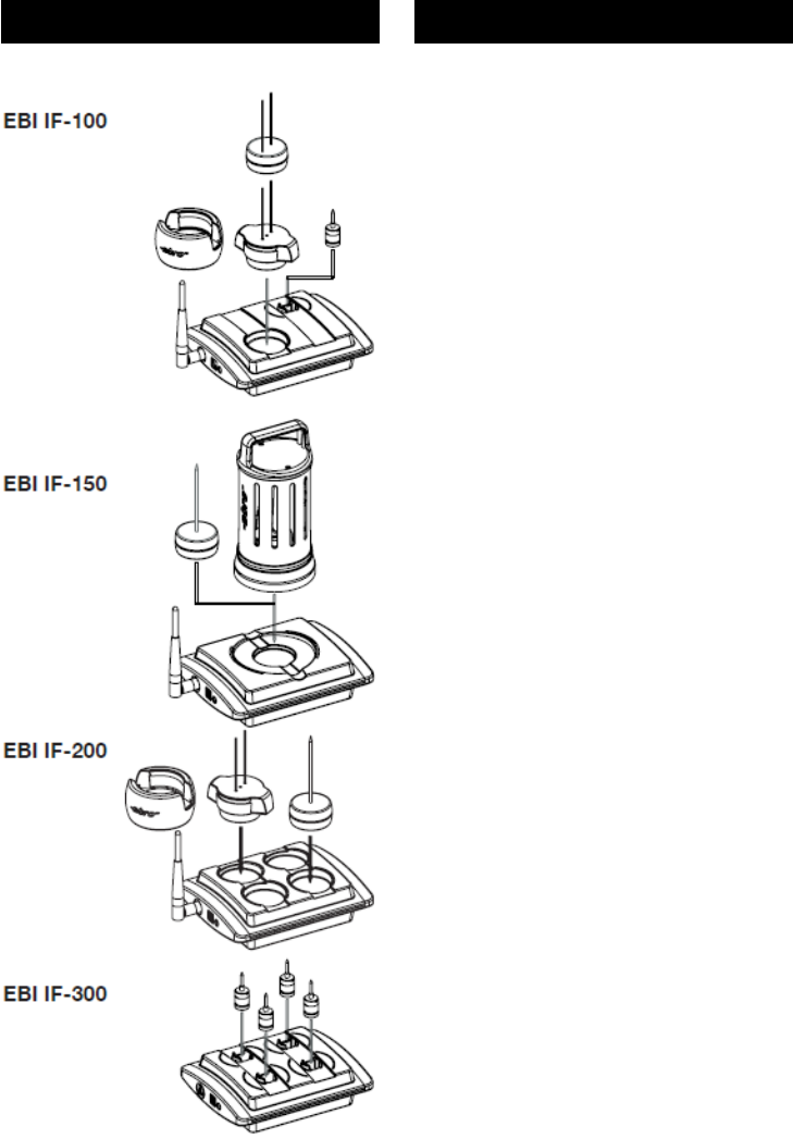
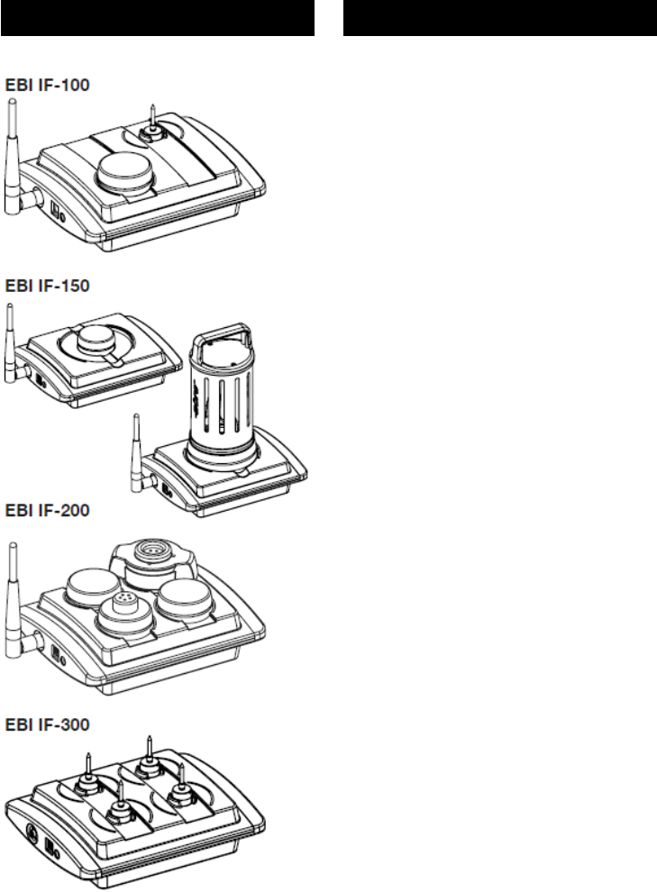
Zum Programmieren und zum Auslesen der
aufgezeichneten Daten im Standardmodus
(siehe Seite 20) werden die Datenlogger in
die Ports des Interface gelegt. Zum
Empfang der Daten im Funkmodus (siehe
Seite 24) muss eine leistungsstarke
Antenne an das Interface angeschlossen
werden.
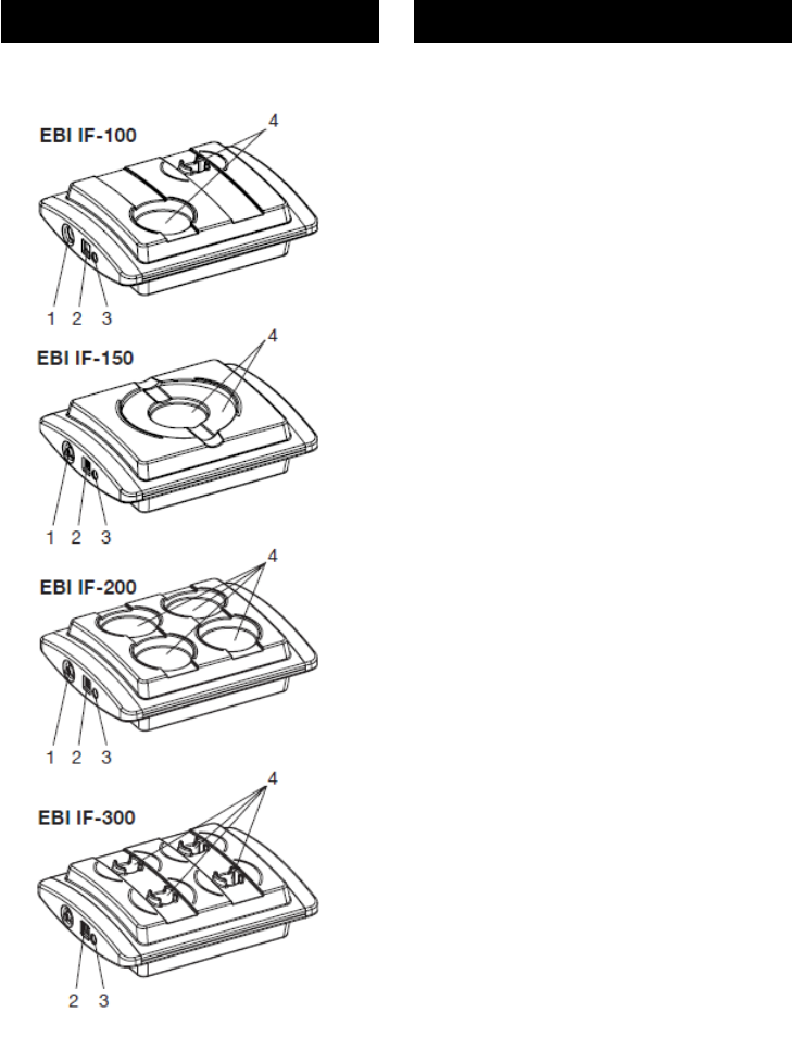
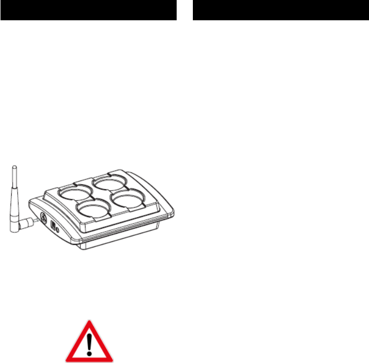
1.............Anschluss für Antenne
2.............Anschluss für USB
3.............Anschluss für Netzteil
4.............Ports für Datenlogger
Näheres zum Programmieren der
Datenlogger und zum Auslesen der
Daten entnehmen Sie bitte der
Gebrauchsanleitung Ihrer
Auswerte-software.

1340-6001 1208 5
English
Français
Overview
The EBI IF-100/150/200/300 interface is a
programming and reading device for EBI
10/15/11 series that also acts as a wireless
receiver for EBI 10 series data loggers.
These data loggers are programmed, and
with EBI 10 data is extracted from them, by
wireless in the 2.4 GHz frequency range.
The interface is connected by a cable to a
PC, from which it is controlled, using
suitable software (e. g. “Winlog.pro”), and
usually also supplied with power. If the PC
cannot supply enough power for the
interface, you can purchase a separate
power supply unit as an accessory.
To program the data logger and extract the
data recorded on it in standard mode (see
Page 21), the device must be placed in the
interface ports. To receive data in wireless
mode (see Page 25) a powerful antenna
must first be connected to the interface.
Structure of the interface:
1........... Antenna connection
2........... USB connection
3........... Power supply unit connection
4........... Data logger ports
For more information about how to
program the data logger, and how to
extract the data, please refer to the
user instructions for your read/write
program.
Vue d’ensemble
L’interface EBI IF-100/150/200/300 est un
dispositif de programmation de la série EBI
10/15/11 et de lecture, ainsi qu’un récepteur
radio pour les enregistreurs de données de
la série EBI 10, lesquels sont programmés
et lus par radio dans la plage de fréquences
des 2,4 GHz.
L’interface est reliée à un ordinateur via un
câble. Elle est pilotée à partir de cet
ordinateur à l’aide d’un logiciel (par ex.
Winlog.pro) et, en règle générale,
également alimentée en énergie à partir de
cette source. Dans le cas où l’ordinateur ne
serait pas en mesure de fournir
suffisamment d’énergie à l’interface, une
alimentation secteur séparée est disponible
en option.
En mode standard (voir page 21), les
enregistreurs sont reliés aux ports de
l’interface aux fi ns de programmation et de
lecture des données enregistrées. En mode
radio, une antenne puissante doit être
raccordée à l’interface pour garantir la
réception des données (voir page 25).
Caractéristiques de l’interface :
1............ Connexion pour l’antenne
2............ Port USB
3............ Connexion pour l’alimentation
secteur
4............ Ports pour les enregistreurs de
données
Pour plus de détails sur la
programmation des enregistreurs et sur
la lecture des données, veuillez-vous
référer à la notice d’utilisation de votre
logiciel d’exploitation.
6
Deutsch
EBI IF-100/150/200/300
Sicherheitshinweise
Verwenden Sie das Gerät nicht in
explosionsgefährdeten Bereichen.
Lebensgefahr!
Achten Sie darauf das Sie das Gerät
nicht so aufzustellen, dass das
Betätigen der Trenneinrichtung
(Netzgerät) erschwert wird!
Bringen Sie das Gerät nicht in eine
Umgebung, die heißer ist als 60°C!
Um Beschädigungen des Gerätes zu
vermeiden, schützen Sie es vor
direktem Kontakt mit Wasser.
Beachten Sie die Schutzklasse des
Gerätes (IP 20).
Das Interface sendet Funksignale im
Frequenzbereich 2,4 GHz aus.
Hierdurch können andere
technische Geräte unter Umständen
erheblich gestört werden!
Verwenden Sie das Interface daher
nur in Bereichen, in denen die
Funkstrahlung keine Gefahr
darstellt!

1340-6001 1208 7
English
Français
Safety Instructions
Do not use the device in areas in
which there is a danger of
explosions.
Danger of death!
Be sure to install the device in such
a way so that the disconnection of
power supply unit easily is
accessible.
Do not introduce the device into an
environment that is hotter than 60°C!
To avoid damaging the device,
protect it from direct contact with
water. Please note the device’s
protection class (IP 20).
The device emits wireless signals in
the 2.4 GHz frequency range. These
may cause significant interference
to other technical devices! For this
reason, only use the device in areas
where these wireless emissions do
not represent a risk!
Consignes de sécurité
N’utilisez pas l’appareil dans des
endroits soumis à des risques
d’explosion.
Danger de mort !
Soyez sûr d’installer le dispositif
dans une telle manière de sorte que
le débranchage de l’unité
d’alimentation d’énergie soit
facilement accessible.
Ne placez pas l’appareil dans un
environnement soumis à des
températures supérieures à 60 °C.
Afi n d’éviter d’endommager
l’appareil, évitez de le mettre en
contact direct avec de l’eau. Veillez à
respecter la classe de protection de
l’appareil (IP 20).
L’interface émet des signaux radio
dans la plage de fréquences des 2,4
GHz. Il est possible que cela
occasionne de sérieuses
perturbations pour d’autres
équipements techniques! Pour cette
raison, veuillez n’utiliser l’interface
que dans des endroits où cette
émission de signaux radio ne
constitue pas un danger!

8
Deutsch
EBI IF-100/150/200/300
Auspacken/Lieferumfang
Überprüfen Sie nach dem Erhalt die
Geräteverpackung und den Inhalt auf
Unversehrtheit. Überprüfen Sie
außerdem, ob der Inhalt der
Geräteverpackung Ihrer Bestellung
entspricht.
Lieferumfang
Im Lieferumfang sind folgende Teile
enthalten:
– Interface EBI IF-100/150/200/300
– USB-Kabel
– Stabantenne 5 dbi (Art.-Bez. AL
111), bei EBI IF-100/200
– diese Gebrauchsanleitung
– CD-ROM mit Treibersoftware
Daneben können in der Lieferung
verschiedene Zubehörteile enthalten
sein:
Beschreibung Bezeichnung
Draht-Antenne AL112
Auswertesoftware Winlog.x
Netzteil AL 120
Sollten Sie Grund zu einer
Beanstandung haben, nehmen Sie
bitte mit uns Kontakt auf. Unsere
Kontaktdaten finden Sie auf der
Umschlagrückseite.

1340-6001 1208 9
English
Français
Unpacking/What is Included in
the Delivery
Check the device packaging and contents
to ensure they are complete and
undamaged. You must also check that the
contents of the packaging match your order.
What is Included in the Delivery
The delivery includes these parts:
– EBI IF-100/150/200/300 interface
– USB cable
– rod antenna 5 dbi (Part Name AL 111),
only EBI IF-100/200
– these operating instructions
– CD-ROM with driver software
The delivery may also include various
accessories:
Description Name
Wire antenna AL 112
Evaluation software Winlog.x
Power supply unit AL 120
If you have any reason for complaint, do
not hesitate to contact us. Our contact
details are printed on the reverse of the
envelope.
Déballage / Fourniture
A réception des appareils, vérifi ez que
l’emballage et le contenu sont intacts.
Vérifiez également si le contenu de
l’emballage correspond bien à votre
commande.
Eléments contenus dans l’emballage
Les éléments suivants sont fournis dans
l’emballage :
– interface EBI IF-100/150/200/300
– cordon USB
– mât-antenne 5 dbi (Réf. pièce AL 111)
chez EBI IF-100/200
– la présente notice d’utilisation
– un CD-ROM avec les pilotes logiciels
Différents accessoires peuvent en outre
être fournis :
Description Désignation
Câble-antenne AL112
Logiciel d’exploitation Winlog.x
Alimentation secteur AL 120
Si vous souhaitez faire une réclamation,
n’hésitez pas à nous contacter. Nos
coordonnées se trouvent au verso de
l’enveloppe.
10
Deutsch
EBI IF-100/150/200/300
Interface in Betrieb nehmen
Die Inbetriebnahme des Interfaces
besteht aus vier Schritten:
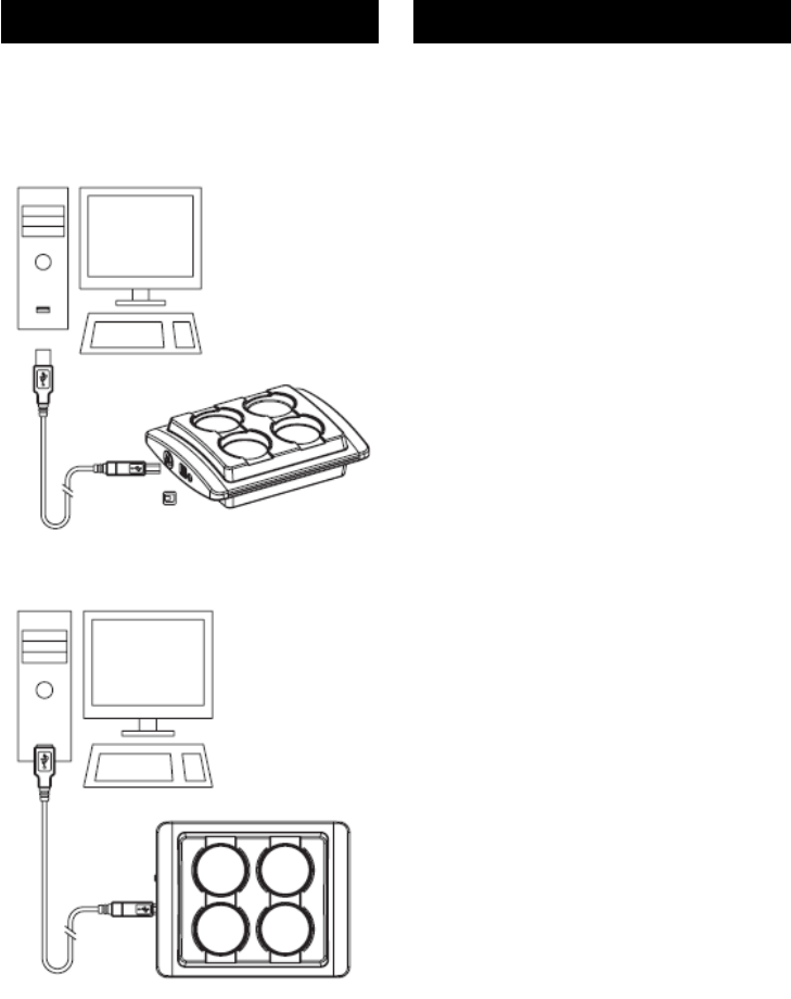
1.) Interface über USB-Kabel mit PC
verbinden
2.) Passende Antenne anschließen
3.) Falls der PC nicht genug Strom
liefert: Netzteil anschließen
4.) Interface-Treiber auf dem PC
installieren
Interface mit PC verbinden
Im Lieferumfang des Interfaces befin-
det sich ein USB-Kabel. Dessen
Stecker mit dem rechteckigen
Querschnitt (Typ A) ist an den PC zu
stecken. Der Stecker mit dem
quadratischen Querschnitt (Typ B)
passt zur Buchse am Interface.
- Stecken Sie die Kabelstecker in die
jeweils passende Buchse am PC
und am Interface. Verwenden Sie
am PC eine High-Power-USB-
Buchse, sofern vorhanden.
Führen Sie diesen Vorgang mit
Gefühl aus und wenden Sie keine
große Kraft an. Die Stecker sind
verpolungssicher und passen nur in
einer bestimmten Ausrichtung in die
jeweilige Buchse.

1340-6001 1208 11
English
Français
Operating the Interface
Bringing the interface into operation
involves four steps:
1.) Connecting the interface to the PC
with a USB cable
2.) Connecting a suitable antenna
3.) Connecting a power supply unit
(only if the PC cannot supply
enough power)
4.) Installing the interface driver on
the PC
Connecting the Interface to the PC
The interface is supplied along with a
USB cable. Insert its plug (type A, with
rectangular cross-section) into the PC.
The square cross-section plug (type B)
fits the socket on the interface.
- Insert the ends of the cable plug into
the appropriate socket on the PC
and on the interface. We
recommend that you use a high-
power USB socket on the PC, if
present.
Take great care throughout this
procedure and do not use excessive
force at any point. The plugs are
polarized and only fi t into the
socket in one particular alignment.
Mise en service de l’interface
La mise en service de l’interface
s’effectue en quatre étapes :
1.) Reliez l’interface à l’ordinateur
via le cordon USB
2.) Branchez l’antenne adaptée
3.) Si l’ordinateur ne peut pas
fournir suffisamment d’énergie :
branchez l’alimentation secteur
4.) Installez le pilote de l’interface sur
l’ordinateur
Connexion de l’interface à
l’ordinateur
L’interface est livrée avec un cordon
USB. Branchez l’extrémité de section
rectangulaire (type A) de ce cordon sur
l’ordinateur. Branchez ensuite
l’extrémité de section carrée (type B)
sur le connecteur correspondant de
l’interface.
- Branchez les connecteurs de câble
aux emplacements correspondants
sur l’ordinateur et l’interface. Si
l’ordinateur en est équipé, utilisez
un port USB haute puissance.
Effectuez cette opération en douceur
et sans forcer. Les prises sont
protégées contre les inversions de
polarité et munies d’un détrompeur.
12
Deutsch
EBI IF-100/150/200/300
Passende Antenne
anschließen
Im Lieferumfang des Interfaces
befinden sich zwei Antennen, eine
Stab-Antenne und eine Draht-Antenne.
Die Stab-Antenne ist für den normalen
Betrieb (sowohl Standard-Modus als
auch Funkmodus) vorgesehen. Die
Draht-Antenne ist für Messungen in
Prozessen mit kritischen
Funkübertragungs-Eigenschaften (z. B.
in Dampfsterilisatoren, Autoklaven,
Öfen etc.) vorgesehen. Beide Antennen
besitzen ein Gewinde passend zur
Antennenbuchse des Interfaces und
werden alternativ auf die Buchse des
Interfaces geschraubt.
Ziehen Sie vor einem Wechsel der
Antennen den Netzstecker bzw. das
USB-Kabel vom Interface ab, so
dass die Statusanzeigen nicht mehr
leuchten.
Es dürfen aus Gründen der
Betriebssicherheit nur die von ebro
gelieferten Antennen an das
Interface angeschlossen werden.
- Schrauben Sie die Stab-Antenne
bzw. den Stecker der Draht-
Antenne an die Buchse des
Interfaces.
Führen Sie diesen Vorgang mit
Gefühl aus und wenden Sie keine
große Kraft an.

1340-6001 1208 13
English
Français
Connecting a suitable antenna
The interface is supplied along with two
antennae: one rod antenna and one
wire antenna.
The rod antenna is designed for normal
operations (in both standard mode and
wireless mode). The wire antenna is
designed to record measurements in
processes that have critical wireless
transmission attributes (e.g. in steam
sterilizers, autoclaves, ovens etc.).
Each antenna has a thread that fits into
the interface’s antenna socket.
Alternatively, they can be screwed into
the interface socket.
Before you change an antenna, pull
the power supply cable or the USB
cable out of the interface so that the
status display lights go out. To
ensure correct operation, you must
only connect antennae supplied by
ebro to the interface.
- Either screw the rod antenna, or the
wire antenna’s plug, into the
interface socket.
Take great care throughout this
procedure and do not use excessive
force at any point.
Branchement de l’antenne
adaptée
L’interface est livrée avec deux
antennes, un mât-antenne et un câble-
antenne.
Le mât-antenne est prévu pour une
utilisation courante (aussi bien en
mode standard qu’en mode radio). Le
mât-antenne est prévu pour les
mesures effectuées dans le cadre de
processus présentant des conditions
critiques de transmission par radio (par
ex. dans des autoclaves, des fours
etc.). Les deux antennes sont équipées
d’un filetage adapté à la bague de
l’antenne de l’interface et peuvent
également être vissées sur la bague de
l’interface.
Avant de changer les antennes,
retirez la prise ou le cordon USB de
l’interface, de sorte que les
indicateurs d’état ne soient plus
allumés. Pour des raisons de
sécurité d’exploitation, seules des
antennes fournies par ebro peuvent
être raccordées à l’interface.
- Vissez le mât-antenne ou la prise
du câble-antenne sur la bague de
l’interface.
Effectuez cette opération en douceur
et sans forcer.
This radio transmitter IC: 7412A-EBIIFXXX has been approved by Industry Canada to operate with the antenna
types listed below with the maximum permissible gain indicated. Antenna types not included in this list, having
a gain greater than the maximum gain indicated for that type, are strictly prohibited for use with this device.
Monopole AN 2400-1901 RS (5 dBi)
Monopole Antenna AL 112 (-7.8 dBi)
Monopole Rod Antenna AN2400-5701 (2 dBi)
PCB Meander Antenna (Inverted F, Monopole: 5 dBi)
14
Deutsch
EBI IF-100/150/200/300
Bei Bedarf: Netzteil
anschließen
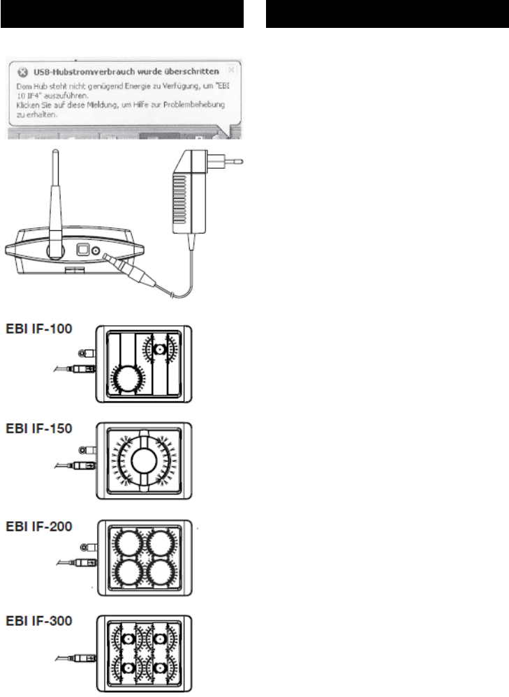
Falls der PC über den USB nicht genug
Strom für den Betrieb des Interfaces
liefern kann, müssen Sie das Interface
mit einem eigenen Netzteil betreiben
(als Zubehör erhältlich). In diesem Fall
erscheint nach dem Anstecken des
Interfaces an den USB des PCs eine
entsprechende Meldung auf dem
Bildschirm.
Nur wenn diese Meldung erscheint,
benötigen Sie das Netzteil.
Verwenden Sie nur das von ebro
gelieferte Netzteil zum Betrieb des
Interfaces. Nur dieses hat die
erforderlichen technischen
Eigenschaften.
- Stecken Sie - falls benötigt – den
Netzstecker in die Netzsteckdose
und den Niederspannungsstecker in
die Buchse am Interface.
Sobald das Interface mit Strom
versorgt ist, leuchten alle Status-
Anzeigen des Interfaces blau.
Interface-Treiber installieren
Im Lieferumfang des Interfaces
befindet sich eine CD-ROM mit der
zugehörigen Treibersoftware. Neben
der Treibersoftware befindet sich auf
der CD-ROM auch die genaue
Anleitung zur Installation der Software.
- Wie Sie die Treibersoftware auf
Ihrem PC installieren, entnehmen Sie
bitte der Anleitung auf der CD-ROM.

1340-6001 1208 15
English
Français
If required, connect a power
supply unit
If the PC cannot supply enough power
along the USB cable to operate the
interface, you must use a separate
power supply to run the interface (this
is available as an accessory). In this
case, a message appears on screen
immediately after you plug the interface
into the PC’s USB port.
You will only need to attach a power
supply unit if this message appears.
Only use the power supply unit
supplied by ebro to operate the
interface. This is the only unit that
has the required technical
functionality.
- If necessary, insert the mains plug
into the mains socket and then
insert the low voltage plug into the
socket on the interface.
As soon as the interface is supplied
with power, all status display indicators
light up blue.
Installing the Interface Driver
The interface is supplied together with
a CD-ROM that holds the required
driver software. This CD-ROM also
contains precise instructions about how
to install the software.
- The instructions on the CD-ROM
will tell you how to install the driver
software on your PC.
Au besoin : branchement
d’une alimentation secteur
Si l’ordinateur ne peut pas fournir
suffisamment d’énergie pour permettre
l’utilisation de l’interface, cette dernière
doit être alimentée par sa propre
alimentation secteur (disponible en
option). Si tel est le cas, un message
correspondant s’affiche à l’écran
lorsque vous avez branché l’interface
sur le port USB de l’ordinateur.
L’alimentation secteur supplémentaire
n’est requise que si ce message
apparaît.
Utilisez exclusivement l’alimenta-
tion secteur fournie par ebro. Seule
cette interface présente les carac-
téristiques techniques requises.
- Si nécessaire, reliez la prise secteur
au secteur et la prise basse tension
à la bague de l’interface.
Dès que l’interface est alimentée en
énergie, les indicateurs de statut de
l’interface s’allument en bleu.
Installation des pilotes de l’interface
L’interface est livrée avec un CD-ROM
contenant les pilotes logiciels requis.
Le CD-ROM contient également les
instructions d’installation précises du
logiciel.
- Respectez les instructions fournies
sur le CD-ROM pour installer les
pilotes logiciels sur votre ordinateur.
16
Deutsch
EBI IF-100/150/200/300
Bedeutung der Farbsignale
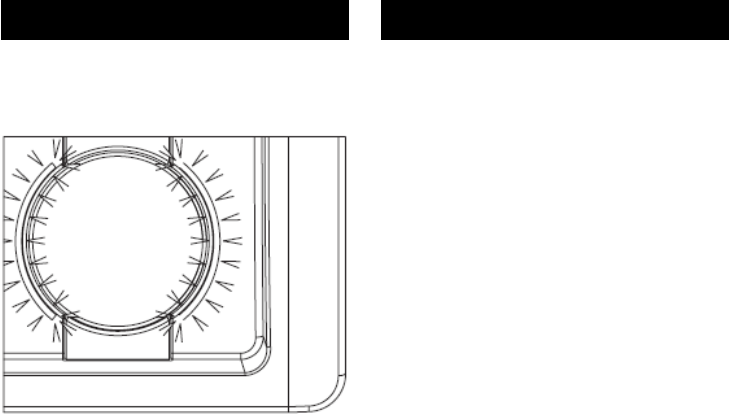
Sobald das Interface mit Strom
versorgt wird, leuchten die Status-
Anzeigen an den Datenlogger-Ports. Je
nachdem, welche Funktion das
Interface gerade ausführt, ändern die
Status-Anzeigen ihre Farbe. Es
bedeuten:
blau Interface betriebsbereit
gelb Programmieren/Auslesen
des Datenloggers im
jeweiligen Port
grün Programmieren/Auslesen
erfolgreich
rot Programmieren/Auslesen
nicht erfolgreich
violett blinkend Funkmodus

1340-6001 1208 17
English
Français
Meaning of the colored status
display lights
The status display lights on the data
logger ports come on as soon as the
interface is supplied with electricity.
These lights change color, depending
on which function the interface is
performing. The colors have these
meanings:
blue interface ready for use
yellow program/extract data from
the data logger in the
particular port
green programming/data
extraction successful
red programming/data
extraction failed
flashing violet wireless mode
Signification des signaux de
couleur
Dès que l’interface est alimentée en
énergie, les indicateurs de statut
s’allument au niveau des ports des
enregistreurs. La couleur des
indicateurs de statut change selon la
fonction en cours d’exécution au niveau
de l’interface. La signifi cation des
différentes couleurs est la suivante :
bleu Interface prête à être
utilisée
jaune Programmation/lecture
de l’enregistreur sur le
port correspondant
vert Programmation/lecture
terminée avec succès
rouge Programmation/lecture
échouée
violet clignotant Mode radio
18
Deutsch
EBI IF-100/150/200/300
Interface-Betriebsarten
(Modi)
Das Interface kann in zwei
verschiedenen Betriebsarten (Modi)
eingesetzt werden:
– im Standard-Modus und
– im Funkmodus.
Beim Standard-Modus wird das
Interface dafür benutzt, um
Datenlogger zu programmieren oder
um alle im Datenlogger gesammelten
Daten auf einmal auszulesen. Hierbei
kann pro Port des Interfaces jeweils ein
Datenlogger programmiert oder
ausgelesen werden.
Im Funkmodus wird das Interface als
Funk-Empfänger eingesetzt. Hierbei
empfängt das Interface laufend die
Signale von Datenloggern, die
ebenfalls im Funkmodus arbeiten und
ihre Messdaten im Takt ihrer Messung
senden. Im Funkmodus können
Funksignale von bis zu 40
Datenloggern parallel empfangen und
verarbeitet werden.
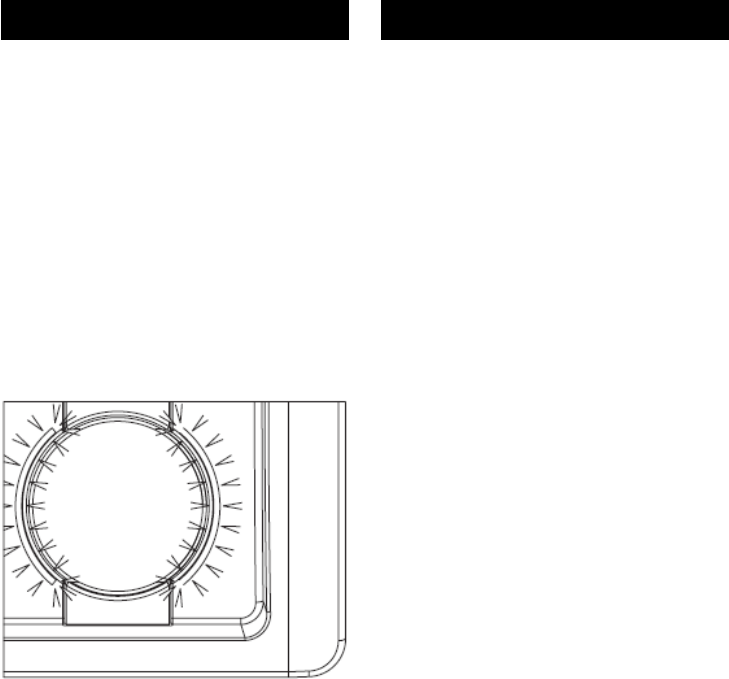
Sie erkennen den Funkmodus des
Interfaces am violetten Blinken der
Status- Anzeigen.

1340-6001 1208 19
English
Français
Interface operating types
(modes)
The interface can be used in two
different operating modes:
– in standard mode and
– in wireless mode.
In standard mode the interface is used
either to program the data logger or to
extract all the data collected in the data
logger at once. In this way a different
data logger can be programmed, or
data can be extracted from it, on each
one of the interface’s ports.
In wireless mode the interface is used
as a wireless receiver. In this situation,
the interface continuously receives
signals from data loggers that are also
running in wireless mode and sending
measurement data as soon as they
record the measurements. When
operating in wireless mode the
interface can receive and process radio
signals from up to 40 data loggers at
the same time.
When the interface is running in
wireless mode, the violet status display
lights fl ash on and off.
Modes d’exploitation
de l’interface
L’interface peut être utilisée dans deux
modes différents :
– en mode standard ou
– en mode radio.
En mode standard, l’interface est
utilisée pour programmer des
enregistreurs de données ou pour
exploiter toutes les données
enregistrées en une fois. Dans ce
mode, il est possible de programmer ou
de lire un enregistreur de données par
port de l’interface.
En mode radio, l’interface est utilisée
en tant que récepteur radio. Dans ce
mode, l’interface reçoit en permanence
les signaux des enregistreurs de
données qui fonctionnent également en
mode radio et transmettent leurs
mesures au rythme où ils les
effectuent. En mode radio, les signaux
radio peuvent être reçus et traités en
parallèle sur 40 enregistreurs de
données.
Le mode radio de l’interface est
identifiable via la couleur violette
clignotante des indicateurs de statut.
20
Deutsch
EBI IF-100/150/200/300
Betrieb im Standard-
Modus
Im Standard-Modus wird das Interface
dafür benutzt, um Datenlogger zu
programmieren oder um alle im
Datenlogger gesammelten Daten auf
einmal auszulesen. Hierbei kann pro
Port des Interfaces jeweils ein
Datenlogger auf einmal programmiert
oder ausgelesen werden.
Um Datenlogger zu programmieren
oder auszulesen, gehen Sie
folgendermaßen vor:
- Bei Datenloggern in einer Silikon-
Schutzbox entfernen Sie zunächst
jeweils das Unterteil der
Silikonschutzbox.
- Legen Sie den Datenlogger mit der
Kunststoffseite nach unten in einen
freien Port des Interfaces.
- Starten Sie bei der
Auswertesoftware auf dem PC den
Programmier- bzw. den
Lesevorgang und folgen Sie den
Anweisungen auf dem Bildschirm.
Solange die Statusanzeige eines Ports
gelb leuchtet, läuft der Programmier-
bzw. Lesevorgang an dem jeweiligen
Datenlogger.
Leuchtet die Statusanzeige eines Ports
grün, dann war der Programmier- oder
Lesevorgang erfolgreich. Leuchtet sie
rot, war der Vorgang nicht erfolgreich.
max. 70°C
max. 70°C
max. 70°C
max. 70°C

1340-6001 1208 21
English
Français
Operation in standard
mode
In standard mode the interface is used
either to program the data logger or to
extract all the data collected in the data
logger at once. In this way a different
data logger can be programmed, or
data can be extracted from it, on each
one of the interface’s ports.
To program a data logger, or extract
data from it, follow these steps:
- If the data logger is enclosed in a
protective silicon box, fi rst remove
the lower part of this box.
- Place the data logger, with its
plastic side facing downwards, in a
free port on the Interface.
- On the PC that is running evaluation
software, start the programming or
extraction process and follow the
on-screen instructions.
If a port’s status display light is yellow,
this means the programming or
extraction process is running on that
particular data logger.
If the port’s status display light is green,
this means the programming or
extraction process was successful. If
this process was not successful, this
light goes to red.
Utilisation en mode
standard
En mode standard, l’interface est
utilisée pour programmer des
enregistreurs de données ou pour
exploiter toutes les données
enregistrées en une fois. Dans ce
mode, il est possible de programmer ou
de lire un seul enregistreur de données
à la fois par port de l’interface.
Pour programmer ou lire des
enregistreurs de données, procédez
comme suit :
- Dans le cas d’enregistreurs livrés
dans un boîtier de protection en
silicone, commencez par retirer la
partie inférieure du boîtier en
silicone.
- Branchez l’enregistreur de données
dans un port libre de l’interface, face
en plastique vers le bas.
- A partir du logiciel d’exploitation
installé sur l’ordinateur, lancez le
processus de programmation ou de
lecture, puis suivez les instructions
à l’écran.
Tant qu’un indicateur de statut d’un
port clignote en jaune, cela signifi e que
le processus de programmation ou de
lecture est en cours sur l‘enregistreur
de données correspondant.
Si l’indicateur de statut d’un port
clignote en vert, cela signifie que le
processus de programmation ou de
lecture s’est déroulé avec succès.
Enfin, s’il clignote en rouge, le
processus a échoué.

22
Deutsch
EBI IF-100/150/200/300
- Setzen Sie bei Datenloggern in
einer Silikon-Schutzbox nach dem
Programmier- bzw. Lesevorgang
das Unterteil der Silikon-Schutzbox
wieder auf.
- Wiederholen Sie den gesamten
Ablauf bei Bedarf für weitere
Datenlogger

1340-6001 1208 23
English
Français
- Once you have completed the
programming or extraction process,
replace the lower part of the data
logger’s protective silicon box.
- Repeat the entire process as
required for the next data logger.
- A l’issue du processus de
programmation ou de lecture, replacez
la partie inférieure du boîtier de
protection en silicone des enregistreurs
qui en sont équipés.
- Répétez l’ensemble du processus pour
les autres enregistreurs de données, le
cas échéant.
24
Deutsch
EBI IF-100/150/200/300
Betrieb im Funkmodus
Im Funkmodus arbeitet das Interface
als reiner Funk-Empfänger. Dabei
empfängt und verarbeitet das Interface
laufend die Signale von Datenloggern,
die ebenfalls im Funkmodus arbeiten
und ihre Messdaten im Takt ihrer
Messung senden. Im Funkmodus
können Funksignale von bis zu 40
Datenloggern parallel empfangen und
verarbeitet werden.
Funkwellen verhalten sich wie Licht
und werden vor allem von Metall und
Beton an der Ausbreitung gehindert.
Um einen guten Empfang zu erreichen,
sollte sich zwischen den Datenloggern
und der Interface-Antenne möglichst
wenig davon befinden. Am besten ist
der Empfang, wenn eine direkte
Sichtverbindung zwischen Daten-
loggern und Interface-Antenne besteht.
Damit ein einwandfreier Empfang der
Funksignale von den Datenloggern
gewährleistet ist, dürfen die
Datenlogger aber auch nicht zu weit
vom Interface entfernt sein. Die
maximale Reichweite der Datenlogger
beträgt bei freier Sicht auf das Interface
etwa 30 m.
Antennen nehmen Funksignale am
besten aus den Richtungen senkrecht
zur Antennenachse auf. Aus diesem
Grund empfiehlt es sich in der Regel,
die Stab-Antenne senkrecht zu stellen.

1340-6001 1208 25
English
Français
Operation in wireless mode
In wireless mode, the interface
operates as a radio receiver. It
continuously receives and processes
signals from data loggers that are also
running in wireless mode and sending
their measurement data as soon as
they record the measurements. When
operating in wireless mode the
interface can receive and process radio
signals from up to 40 data loggers at
the same time.
Radio waves behave like light, and
metal and concrete objects, in
particular, prevent the waves from
being diffused. To ensure clear
reception, the space between the data
loggers and the interface antenna
should be kept as clear as possible of
objects of this type. The best reception
is achieved when there is a direct line
of sight between the data logger and
the interface antenna.
The data logger should also be sited
fairly close to the interface to ensure
the radio signals can be received
clearly and easily. The data logger has
a maximum range of approximately 30
m from the interface if there are no
obstacles in the way.
Antennae receive the clearest radio
signals from directions that are vertical
to their axis. For this reason we
recommend that the rod antenna is
sited vertically.
Utilisation en mode radio
En mode radio, l’interface fonctionne
comme un pur récepteur radio. Dans
ce mode, l’interface reçoit et traite en
permanence les signaux des
enregistreurs de données qui
fonctionnent également en mode radio
et transmettent leurs mesures à la
fréquence des mesures qu’ils
effectuent. En mode radio, les signaux
radio peuvent être reçus et traités en
parallèle sur 40 enregistreurs de
données.
Les ondes radio se comportent comme
la lumière et leur dispersion est avant
tout entravée par le métal et le béton.
Afin de garantir une réception de bonne
qualité, il est recommandé de placer
les enregistreurs de données aussi
près que possible de l’antenne de
l’interface. La réception est optimale
lorsqu’un lien visuel direct est possible
entre les enregistreurs et l’antenne de
l’interface.
Afin de garantir une réception optimale
des signaux radio par les enregistreurs
de données, ces derniers ne doivent
cependant pas se trouver trop éloignés
de l’interface elle-même. Dans un
environnement dégagé, la portée
maximale des enregistreurs de
données est de 30 mètres environ.
La réception des signaux est optimale
au niveau des antennes lorsqu’ils sont
reçus perpendiculairement à l’axe des
antennes. Pour cette raison, il est en
général recommandé de placer le
mâtantenne verticalement.

26
Deutsch
EBI IF-100/150/200/300
Es dürfen aus Gründen der
Betriebssicherheit und der
Vermeidung von Störungen nur die
von ebro gelieferten Antennen an
das Interface angeschlossen
werden.
Für Messungen in Geräten, bei denen
der Funkmodus eingesetzt werden soll,
ist die mitgelieferte Draht-Antenne
vorgesehen.
Viele Geräte haben ein Metallgehäuse,
das für die Funksignale der
Datenlogger undurchlässig ist. Damit
die Signale das Interface trotzdem
erreichen, muss sich die Draht-Antenne
im Gerät befinden.

1340-6001 1208 27
English
Français
To ensure correct operation, and to
avoid interference, we recommend
that only antennas supplied by ebro
are connected to the interface.
The wire antenna supplied with the
interface is designed for devices which
are to be used in wireless mode.
Many devices have metal cases which
obstruct the data logger’s radio signals.
Despite this, these signals can still be
sent to the interface if the wire antenna
is fitted into the device.
Pour des raisons de sécurité
d’exploitation et afi n d’éviter toute
interférence, seules des antennes
fournies par ebro peuvent être
raccordées à l’interface.
Le câble-antenne fourni est prévu pour
des mesures sur des appareils devant
utiliser le mode radio.
De nombreux appareils sont équipés
d’un boîtier en métal qui ne laissent
pas passer les signaux radio des
enregistreurs de données. Afin que les
signaux parviennent tout de même à
l’interface, le câble-antenne de fil doit
se trouver dans l’appareil.

28
Deutsch
EBI IF-100/150/200/300
Was tun wenn…
...die Statusanzeigen dunkel
bleiben?
In diesem Fall wird das Interface
offenbar nicht mit Strom versorgt.
- Prüfen Sie, ob der PC
eingeschaltet ist, ob die Stecker
des USB-Kabels richtig sitzen
und ob die verwendete USB-
Buchse des PC eine High-Power-
Buchse ist (siehe Seite 14).
- Falls ein Netzteil eingesetzt wird:
Prüfen Sie, ob die Stecker des
Netzteils richtig mit der Steckdose
und mit dem Interface verbunden
sind.
...der PC „Interface nicht
gefunden“ meldet?
- Prüfen Sie, ob die Status-
anzeigen des Interface leuchten.
Wenn nicht, gehen Sie vor wie es
oben unter „Statusanzeigen
bleiben dunkel“ beschrieben ist.
- Überprüfen Sie die USB-
Verbindung zwischen Interface
und PC.
- Prüfen Sie, ob die richtigen
Treiber installiert sind (siehe Anleitung
zur Treiber-Installation auf der
mitgelieferten Treiber-CD-ROM).

1340-6001 1208 29
English
Français
What to do, if…
...the status display lights remain
dark?
In this case, it is clear that no power is
reaching the interface.
- Check that the PC is switched on,
that the USB cable plugs are
inserted correctly and whether the
USB socket on the PC is a high-
power socket (see Page 15).
- If an external power supply unit is
being used, check that its plug is
correctly connected to the socket
and the interface.
...the PC responds with
“Interface not found”
- Check that the interface’s status
display lights are on. If not, carry
out the same checks as you
would for if the status display
remains dark.
- Check the USB connection
between the interface and the
PC.
- Check you have installed the
correct drivers (see the
instructions for installing the
drivers on the CD-ROM supplied
with the interface).
Que faire quand…
...les indicateurs de statut ne
s’allument pas ?
Si tel est le cas, cela signifie que
l’interface n’est manifestement pas
alimentée en énergie.
- Vérifiez que l’ordinateur est bien
sous tension, que les
connecteurs du cordon USB sont
correctement enfi chés et que le
port USB utilisé sur l’ordinateur
est vraiment un port haute
puissance (voir page 15).
- Si une alimentation secteur est
utilisée : vérifi ez que les
connecteurs de l’alimentation
sont correctement reliés à la prise
secteur et à l’interface.
...l’ordinateur affi che le
message « Interface introuvable
» ?
- Vérifiez que les indicateurs de
statut de l’interface clignotent.
Dans le cas contraire, procédez
comme indiqué précédemment
dans la réponse à la question «
Que faire si les indicateurs de
statut ne s’allument pas ? ».
- Vérifiez la connexion USB entre
l’interface et l’ordinateur.
- Vérifiez que les bons pilotes ont
été installés (voir les instructions
relatives à l’installation des pilotes
fournies sur le CD-ROM livré
avec l’interface).

30
Deutsch
EBI IF-100/150/200/300
...keine Verbindung zum
Datenlogger zustande kommt?
- Prüfen Sie, ob die Datenlogger im
Funkmodus arbeiten und Sie die
Datenlogger im Standard-Modus
auslesen wollen. Datenlogger
und Interface müssen in
derselben Betriebsart arbeiten,
damit eine Kommunikation
zustande kommt.
Wie Sie den Betriebszustand der
Datenlogger prüfen können,
entnehmen Sie bitte der Anleitung
zu Ihrer Programmiersoftware auf
dem PC.
- Prüfen Sie, ob das Interface den
richtigen Funkkanal (siehe
Programmierprotokoll der
Software für die auszulesenden
Datenlogger) für die
Kontaktversuche benutzt.
Arbeiten Datenlogger und
Interface auf verschiedenen
Funkkanälen, kommt kein Kontakt
zustande.

1340-6001 1208 31
English
Français
...no connection is established to
the data logger?
- Check whether the data loggers
are running in wireless mode and
you have selected data extraction
from the data loggers in standard
mode. To communicate with each
other, the data logger and
interface must be running in the
same operating mode.
Please refer to the programming
software instructions on the PC to fi
nd out how you check the data
logger’s operating mode.
- Check that the interface is using
the correct radio channel for its
attempts to establish contact
(refer to the software’s
programming log for the data
logger from which data is to be
extracted). The data logger and
interface will not be able to
contact each other if they are
running on different radio
channels.
....il n’est pas possible d’établir la
connexion avec l’enregistreur de
données ?
- Vérifi ez que les enregistreurs de
données sont en mode radio et
que vous souhaitez bien lire les
enregistreurs en mode standard.
Pour pouvoir communiquer, les
enregistreurs de données et
l’interface doivent fonctionner sur
le même mode d’exploitation.
Consultez le manuel du logiciel
d’exploitation installé sur votre
ordinateur pour savoir comment
vérifier le mode de fonctionnement
des enregistreurs de données.
- Vérifiez si l’interface utilise le bon
canal radio (voir le protocole de
programmation du logiciel pour
les enregistreurs de données à
lire) lorsqu’elle essaie d’établir le
contact. Si les enregistreurs de
données et l’interface utilisent des
canaux radio différents, aucun
contact n’est établi.

32
Deutsch
EBI IF-100/150/200/300
Reinigung und Pflege
Reinigen Sie das Gerät mit einem nur
leicht feuchten Tuch.
Verwenden Sie kein Lösungsmittel wie
z. B. Aceton, da dieses den Kunststoff
angreift.
Entsorgung
Sollte das Interface
gebrauchsuntauglich geworden sein,
müssen Sie es fach- und
umweltgerecht entsorgen.
Entsorgen Sie das Interface
keinesfalls über den Restmüll,
sondern geben Sie es an den
Hersteller zurück.

1340-6001 1208 33
English
Français
Cleaning and Maintenance
Use a damp cloth to clean the
Interface.
Do not use a solvent, such as acetone,
because this damages the plastic.
Disposal
If the device becomes no longer fi t for
purpose, it must be disposed of in a
suitable, environmentally-friendly
manner.
Do not, under any circumstances,
simply dispose of it in domestic
garbage. You must return it to the
manufacturer.
Nettoyage et entretien
Pour nettoyer l’appareil, utilisez un chif-
fon légèrement humide.
N’utilisez pas de détergent, comme
l’acétone par exemple, car cela
attaque le plastique.
Elimination
Lorsque l’interface sera hors d’usage, il
vous faudra l’éliminer selon la régle-
mentation en vigueur et de manière
écologique.
Ne jetez surtout pas l’interface avec
les ordures ménagères ; renvoyez-la
au fabricant.
.

34
Deutsch
EBI IF-100/150/200/300
Technische Daten
Stromversorgung über USB (High-
Power USB 500 mA)
oder externes Netzteil
Art.-Bez. AL 120
Funkschnittstelle 2,4 GHz IEEE
802.15.4
USB-Anschluss Typ B 500 mA
Antennenanschluss RP-SMA
Betriebstemperatur 30 bis +60 °C
Lagerung -40 bis +60 °C
Schutzart IP20
Abmessungen
(L x B x H) 150 x 180 x 45 mm
Gehäusematerial ABS
Gewicht ca. 358 g
Zulassungen
Das Interface EBI IF-100/200 besitzt
folgende Zulassungen:
Funk:
Dieses Gerät ist getestet nach ETSI EN
Dieses Gerät ist getestet nach CFR 47
Part 15
FCC Regeln und Vorschriften
CFR 47 Part 15 Subpart B and C May
2007
FCC ID: VQ5-EBIIFXXX
Es erfüllt die Anforderungen von Part
15, FCC Regeln.
Dieses Gerät ist getestet nach RSS
Regeln
RSS Regeln und Vorschriften
RSS-Gen Issue 2, RSS-102 Issue 2,
RSS-210 Issue 7
IC: 7412A-EBIIFXXX
Dieses Gerät erfüllt die Anforderungen
der RSS Regeln.

1340-6001 1208 35
English
Français
Technical Data
Power supply USB (high power USB
500 mA)
or external power supply unit
Part Name AL 120
Wireless interface 2.4 GHz IEEE
802.15.4
USB port Type B 500 MA
Antenna port RP-SMA
Operating temperature -30 to +60°C
Storage -40 to +60°C
Protection type IP20
Dimensions Plan
(L x W x H) 150 x 180 x 45 mm
Housing material ABS
Weight approximately 358 g
Approvals
The EBI IF-100/200 Interface has these
approvals:
Wireless:
This device has been tested against
ETSI EN:
This device has been tested against
CFR 47 Part 15 FCC
Rules and Regulations
CFR 47 Part 15 Subpart B and C May
2007
FCC ID: VQ5-EBIIFXXX
This device complies with part 15 of the
FCC Rules.
This device has been tested against
RSS Rules RSS
Rules and Regulations
RSS-Gen Issue 2, RSS-102 Issue 2,
RSS-210 Issue 7
IC: 7412A-EBIIFXXX
This device complies with RSS Rules.
Caractéristiques techniques
Alimentation via USB (USB haute
puissance 500 mA)
ou alimentation secteur externe
Réf. pièce AL 120
Interface radio 2,4 GHz IEEE 802.15.4
Port USB Type B 500 mA
Connexion antenne RP-SMA
Température d’utilisation -30 à +60 °C
Stockage -40 à +60 °C
Type de protection IP20
Dimensions
Vue d’en haut
(L x l x h) 150 x 180 x 45 mm
Matériau du boîtier ABS
Poids env. 358 g
Homologations
L’interface EBI IF-100/200 a reçu les
homologations suivantes :
Radio :
Ce dispositif a été testé contre ETSI FN
Ce dispositif a été testé contre le CFR
47 Partie 15
Règles et règlements de la FCC
CFR 47 partie 15 sous-partie B et C
Mai 2007
FCC ID: VQ5-EBIIFXXX
Ce dispositif est conforme à la partie 15
du règlement de la FCC
Ce dispositif a été testé contre RSS
règles
RSS règles et règlements
RSS - Gen Issue 2, RSS - 102 Issue2,
RSS - 210 Issue 7
IC: 7412A-EBIIFXXX
Ce dispositif est conforme aux règles
de RSS

36
Deutsch
EBI IF-100/150/200/300
Die folgenden Bedingungen müssen erfüllt werden:
(1) Dieses Gerät darf keine Störungen verursachen,
(2) Externe Störungen dürfen die Funktion nicht beein-
trächtigen,
einschließlich Störungen die Fehlfunktionen
verursachen könnten.
Dieses Gerät wurde für die Verwendung einer internen
Antenne konzipiert. Andere Antennen dürfen nicht
verwendet werden.
Änderungen jeglicher Art am Gerät führen zum
Erlöschen der Betriebserlaubnis.
Bedienungsanleitungen können unter www.ebro.com
aus dem Internet geladen werden.

1340-6001 1208 37
English
Français
Operation is subject to the following two conditions:
(1) This device may not cause harmful interference, and
(2) This device must accept any interference received
including interference that may cause undesired ope-
ration.
This device has been designed to operate with an
internal antenna.
Other Antennas are strictly prohibited for use with this
device.
Changes or modifications of the device could void the
user’s authority to operate the equipment.
Users manual or instruction manual may downloaded at
www.ebro.com over the internet.
Opération est soumise aux deux conditions suivantes
(1) ce dispositif ne doit pas provoquer des interférences
nuisibles, et
(2) ce dispositif doit accepter toute interférence reçue
Y compris celles susceptibles de provoquer un
fonctionnement
Ce dispositif a été conçu pour fonctionner avec une
antenne interne.
D‘autres antennes sont strictement interdites par ce
dispositif
Les changements ou modifications de l‘appareil peut
retirer à l‘utilisateur de faire fonctionner l‘équipement..
Manuel de l‘utilisateur ou de manuel d‘instructions,
risque téléchargée à www.ebro.com au-dessus de
l‘Internet.

Zentrale / Headquarters / Centrale
Xylem Analytics Germany GmbH
ebro
Peringerstr. 10
85055 Ingolstadt, Germany
Phone: +49 841 95478-0
Fax: +49 841 95478-80
Internet: www.ebro.com
E-Mail: ebro@xyleminc.com
Service-Adresse / Service Address / Adress du Service
Xylem Analytics Germany GmbH
ebro Service
Dr.-Karl-Slevogt-Str. 1
82362 Weilheim, Germany
…………………………………………………………………………………….
Hersteller / Producer / Fabricant
Xylem Analytics Germany GmbH
Dr.-Karl-Slevogt-Str. 1
82362 Weilheim, Germany