YDI Wireless ETH-ANT-LR Wireless LAN User Manual EtherAnt II v3 0
YDI Wireless Wireless LAN EtherAnt II v3 0
UserManual.wiki
>
YDI Wireless
>
ETH ANT LR User Manual
users manual
Navigation menu
Upload a User Manual
Namespaces
Wiki Guide
HTML
PDF
Info
Views
User Manual
Discussion / Help
Navigation
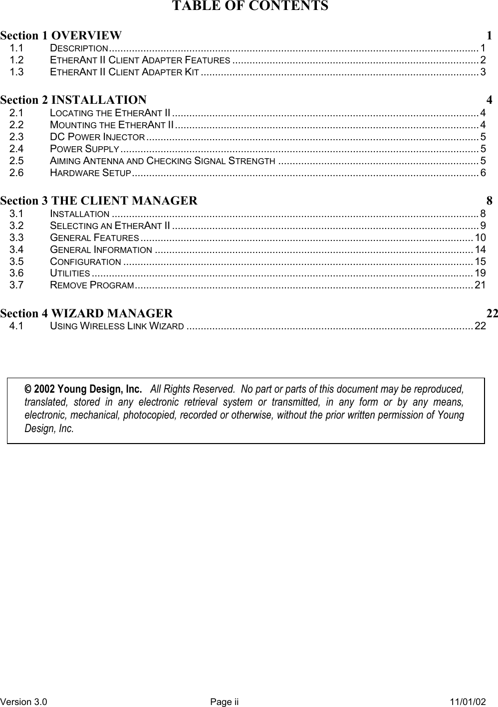
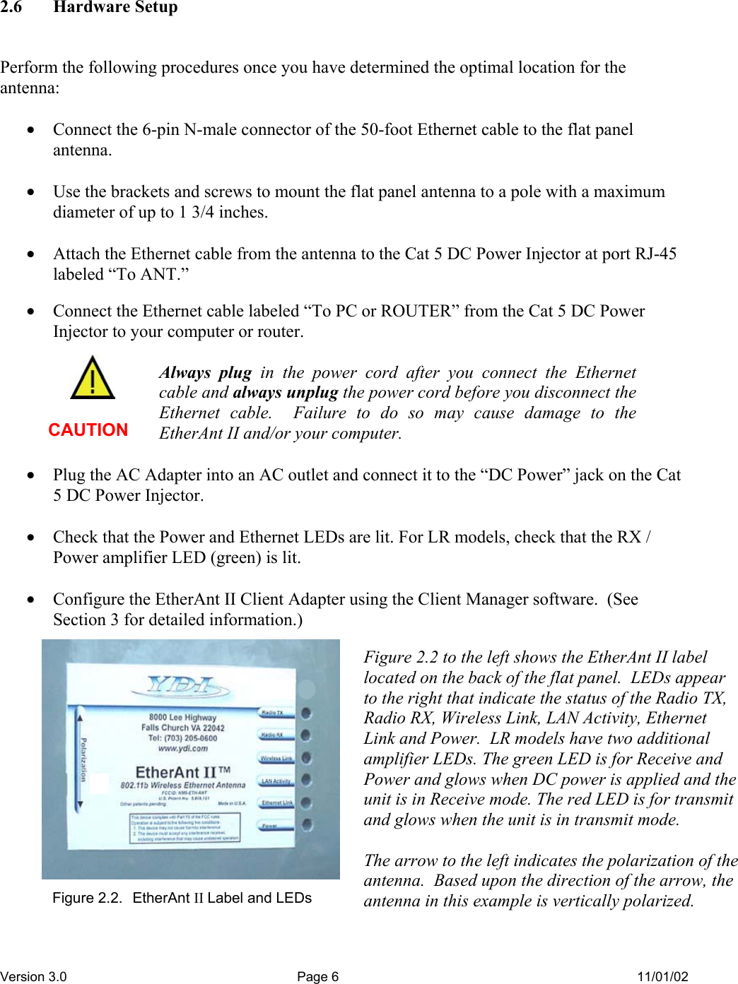
![Version 3.0 Page 5 11/01/02 2.3 DC Power Injector The Cat 5 DC Power Injector is not in a waterproof enclosure and must be protected from the weather. It can be permanently mounted to a surface using the double stick tape found on the back of it. 2.4 Power Supply The EtherAnt II antenna kit normally comes with a 110VAC power supply that has a standard barrel plug [center pin positive (+) tip and outer ring negative (-)]. (220 VAC power supplies are available as an option.) Although normally provided with a power supply, any power source meeting the following specifications can be used: EtherAnt II 12-24VDC @ 500 mA maximum cable length: 300 feet EtherAnt II-LR 15VDC @ 1300 mA maximum cable length: 100 feet CAUTION: Operating the EtherAnt-LR version with more than 15 VDC will damage it. Operating it with less than 15 VDC will cause improper operation. 2.5 Aiming Antenna and Checking Signal Strength The EtherAnt II has signal strength indicator, which can be monitored by the Client Manager software to help optimize the aiming of the antenna. If you are using an Orinoco or YDI Access Point in your wireless network, you can also use the Link Test capability of the AP Manager software to monitor the signal strength of the Ether Ant II into the base unit. Figure 2.1. Outdoor Pole Mount InstallationFigure 2.1 shows the antenna in typical horizontally polarized installation. It must be carefully aimed at the base antenna and be mounted with the same polarization. The housing is sealed to prevent water from entering the antenna. The round connector must also be sealed after it is plugged into the antenna. Be sure to provide strain relief the Ethernet cable as well. If this EtherAnt II antenna is aimed at a vertically polarized omni-directional or sector base station antenna, it must be mounted vertically polarized using the other mounting stud on the back.](https://usermanual.wiki/YDI-Wireless/ETH-ANT-LR/User-Guide-282266-Page-8.png)