YDI Wireless WL2400-ISA Wireless LAN Card with Amplifier User Manual FOR AMPLIFIER

YDI Wireless Wireless LAN Card with Amplifier FOR AMPLIFIER

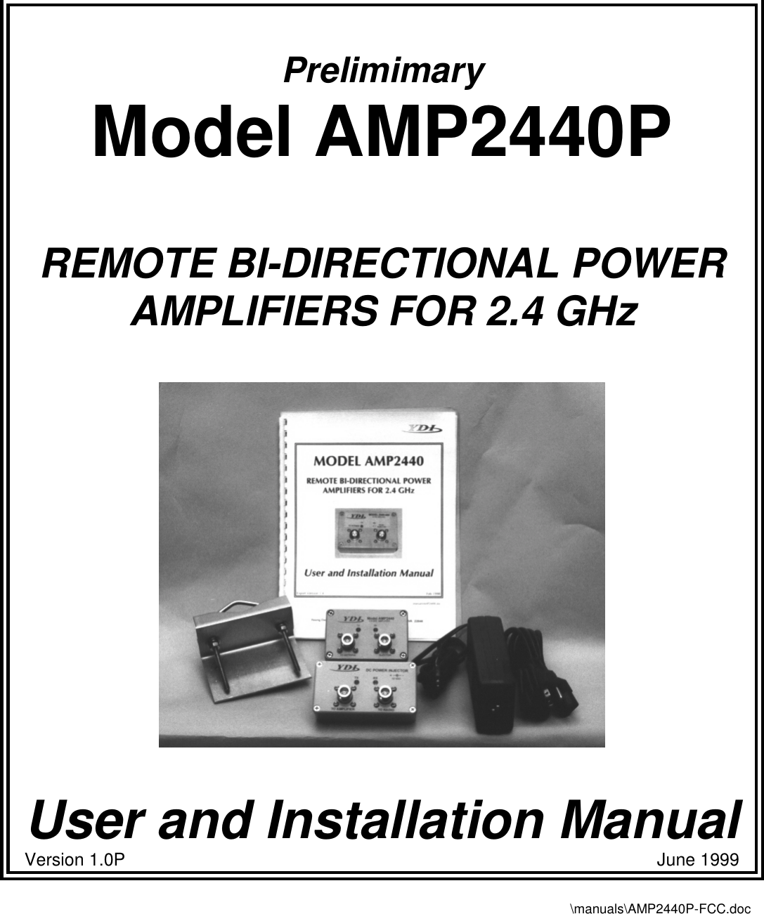
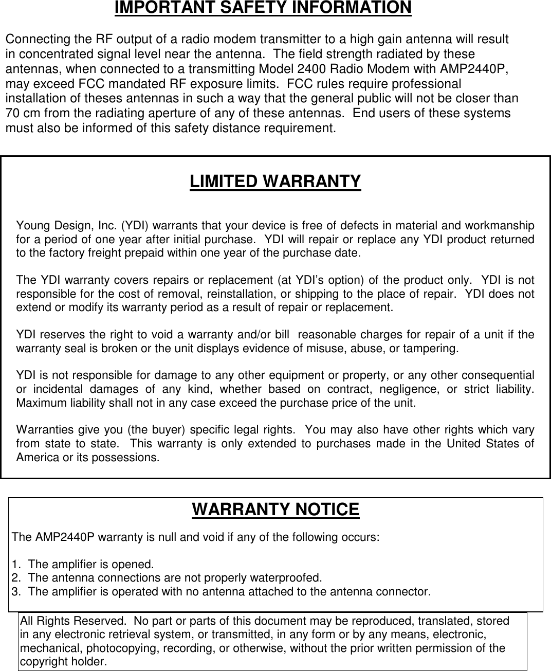
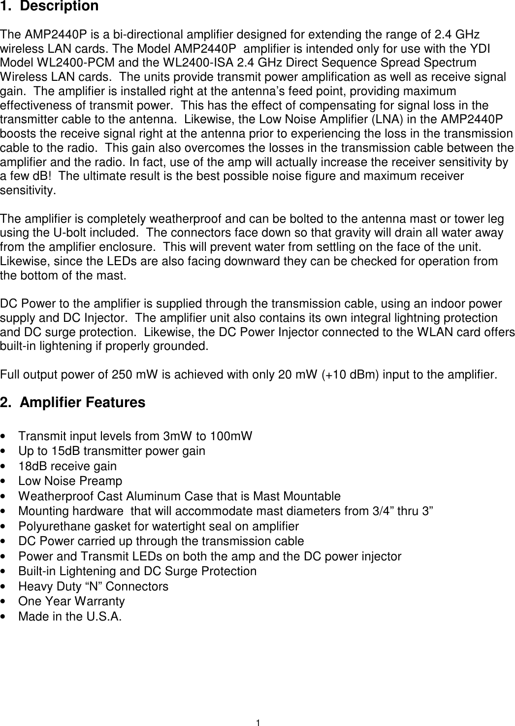
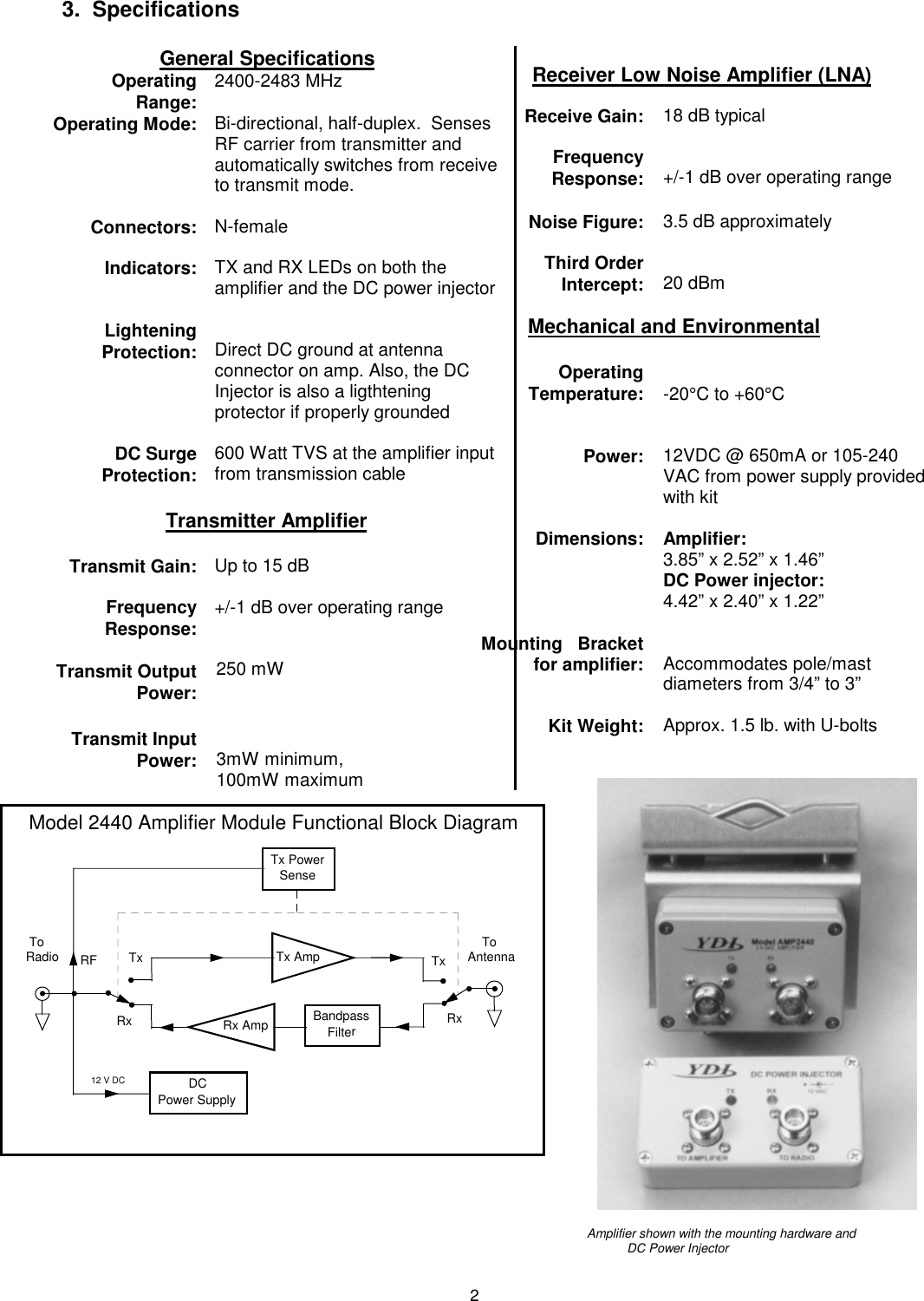
USER MANUAL FOR AMPLIFIER

PrelimimaryModel AMP2440PREMOTE BI-DIRECTIONAL POWERAMPLIFIERS FOR 2.4 GHzUser and Installation ManualVersion 1.0P                                                                                                            June 1999\manuals\AMP2440P-FCC.doc
IMPORTANT SAFETY INFORMATIONConnecting the RF output of a radio modem transmitter to a high gain antenna will resultin concentrated signal level near the antenna.  The field strength radiated by theseantennas, when connected to a transmitting Model 2400 Radio Modem with AMP2440P,may exceed FCC mandated RF exposure limits.  FCC rules require professionalinstallation of theses antennas in such a way that the general public will not be closer than70 cm from the radiating aperture of any of these antennas.  End users of these systemsmust also be informed of this safety distance requirement.LIMITED WARRANTYYoung Design, Inc. (YDI) warrants that your device is free of defects in material and workmanshipfor a period of one year after initial purchase.  YDI will repair or replace any YDI product returnedto the factory freight prepaid within one year of the purchase date.The YDI warranty covers repairs or replacement (at YDI’s option) of the product only.  YDI is notresponsible for the cost of removal, reinstallation, or shipping to the place of repair.  YDI does notextend or modify its warranty period as a result of repair or replacement.YDI reserves the right to void a warranty and/or bill  reasonable charges for repair of a unit if thewarranty seal is broken or the unit displays evidence of misuse, abuse, or tampering.YDI is not responsible for damage to any other equipment or property, or any other consequentialor incidental damages of any kind, whether based on contract, negligence, or strict liability.Maximum liability shall not in any case exceed the purchase price of the unit.Warranties give you (the buyer) specific legal rights.  You may also have other rights which varyfrom state to state.  This warranty is only extended to purchases made in the United States ofAmerica or its possessions.All Rights Reserved.  No part or parts of this document may be reproduced, translated, storedin any electronic retrieval system, or transmitted, in any form or by any means, electronic,mechanical, photocopying, recording, or otherwise, without the prior written permission of thecopyright holder.WARRANTY NOTICEThe AMP2440P warranty is null and void if any of the following occurs:1.  The amplifier is opened.2.  The antenna connections are not properly waterproofed.3.  The amplifier is operated with no antenna attached to the antenna connector.
2TABLE OF CONTENTS1.  DESCRIPTION.....................................................................................................................................................................12.  AMPLIFIER FEATURES....................................................................................................................................................13.  SPECIFICATIONS...............................................................................................................................................................24.  AMPLIFIER KIT..................................................................................................................................................................35.  INSTALLATION AND CABLING INSTRUCTIONS ......................................................................................................46.  AMPLIFIER CONNECTIONS AND INDICATORS........................................................................................................57.  DC POWER INJECTOR CONNECTIONS AND INDICATORS...................................................................................58.  POWER SUPPLY.................................................................................................................................................................69.  OPERATION.........................................................................................................................................................................6TABLE A - CONVERSIONS FROM DBM TO WATTS ......................................................................................................7TABLE B - TYPICAL CABLE ATTENUATION VALUES .................................................................................................7TABLE C - AMP2440P TYPICAL INSTALLATION ...........................................................................................................9
11. DescriptionThe AMP2440P is a bi-directional amplifier designed for extending the range of 2.4 GHzwireless LAN cards. The Model AMP2440P  amplifier is intended only for use with the YDIModel WL2400-PCM and the WL2400-ISA 2.4 GHz Direct Sequence Spread SpectrumWireless LAN cards.  The units provide transmit power amplification as well as receive signalgain.  The amplifier is installed right at the antenna’s feed point, providing maximumeffectiveness of transmit power.  This has the effect of compensating for signal loss in thetransmitter cable to the antenna.  Likewise, the Low Noise Amplifier (LNA) in the AMP2440Pboosts the receive signal right at the antenna prior to experiencing the loss in the transmissioncable to the radio.  This gain also overcomes the losses in the transmission cable between theamplifier and the radio. In fact, use of the amp will actually increase the receiver sensitivity bya few dB!  The ultimate result is the best possible noise figure and maximum receiversensitivity.The amplifier is completely weatherproof and can be bolted to the antenna mast or tower legusing the U-bolt included.  The connectors face down so that gravity will drain all water awayfrom the amplifier enclosure.  This will prevent water from settling on the face of the unit.Likewise, since the LEDs are also facing downward they can be checked for operation fromthe bottom of the mast.DC Power to the amplifier is supplied through the transmission cable, using an indoor powersupply and DC Injector.  The amplifier unit also contains its own integral lightning protectionand DC surge protection.  Likewise, the DC Power Injector connected to the WLAN card offersbuilt-in lightening if properly grounded.Full output power of 250 mW is achieved with only 20 mW (+10 dBm) input to the amplifier.2.  Amplifier Features•  Transmit input levels from 3mW to 100mW•  Up to 15dB transmitter power gain•  18dB receive gain•  Low Noise Preamp•  Weatherproof Cast Aluminum Case that is Mast Mountable•  Mounting hardware  that will accommodate mast diameters from 3/4” thru 3”•  Polyurethane gasket for watertight seal on amplifier•  DC Power carried up through the transmission cable•  Power and Transmit LEDs on both the amp and the DC power injector•  Built-in Lightening and DC Surge Protection•  Heavy Duty “N” Connectors•  One Year Warranty•  Made in the U.S.A.
2       3.  SpecificationsGeneral Specifications     OperatingRange: 2400-2483 MHzOperating Mode: Bi-directional, half-duplex.  SensesRF carrier from transmitter andautomatically switches from receiveto transmit mode.Connectors: N-femaleIndicators: TX and RX LEDs on both theamplifier and the DC power injectorLighteningProtection: Direct DC ground at antennaconnector on amp. Also, the DCInjector is also a ligthteningprotector if properly groundedDC SurgeProtection: 600 Watt TVS at the amplifier inputfrom transmission cableTransmitter AmplifierTransmit Gain: Up to 15 dBFrequencyResponse:Transmit OutputPower:+/-1 dB over operating range250 mWTransmit InputPower: 3mW minimum,100mW maximumReceiver Low Noise Amplifier (LNA)Receive Gain: 18 dB typicalFrequency Response: +/-1 dB over operating rangeNoise Figure: 3.5 dB approximatelyThird OrderIntercept: 20 dBmMechanical and EnvironmentalOperatingTemperature: -20°C to +60°CPower: 12VDC @ 650mA or 105-240VAC from power supply providedwith kitDimensions: Amplifier:3.85” x 2.52” x 1.46”DC Power injector:4.42” x 2.40” x 1.22” Mounting   Bracketfor amplifier: Accommodates pole/mastdiameters from 3/4” to 3”Kit Weight: Approx. 1.5 lb. with U-bolts                         Amplifier shown with the mounting hardware andDC Power InjectorTx PowerSense ToRadioDCPower Supply12 V DCRxTx Tx AmpRx Amp BandpassFilterTx    ToAntennaModel 2440 Amplifier Module Functional Block DiagramRFRx
3IMPORTANT FCC REGULATORY INFORMATIONThe AMP2440P and the YDI WLAN 2400 WLAN cards must be professionally installed.  Table(1) shows the FCC approved antennas that can be used with and without the YDI AMP2440P.It is the responsibility of the installer to ensure that when used in the United States (or whereFCC rules apply) under Part 15 regulations, only these configurations can be used.TABLE (1)Antennas  Certified for use with the WL2400 and AMP2440PMODEL DESCRIPTION Minimum SafeUncontrolledExposure DistanceMinimum SafeControlledExposure DistanceY2412 12 dB gain Yagi Antenna 20cm 20cmY2414 14 dB gain Yagi Antenna 22cm 20cmA2.45 FP12 12 dB gain flat Panel Antenna 20cm 20cmA2.45 FP18 18 dB gain flat Panel Antenna 35cm 20cmA2.45 LP17 17 dB gain long Panel Antenna 32cm 20cmA2.45 LP15 15 dB gain long Panel Antenna 25cm 20cmA2408 8 dB gain Omni-directionalAntenna 20cm 20cmA2412 12 dB gain Omni-directionalAntenna 20cm 20cmPT2421 21 dB gain Grid Dish Antenna 50cm 22cmPT2424 24 dB gain Grid Dish Antenna 70cm 32cmUncontrolled exposure distances is where the power density is 1mW/cm2 .  Controlledexposure distances is where the power density is 5mW/cm2.  The antennas must be installedsuch that there will be no person closer than the specified distances in front of directionalantennas or directly beside the Omni antennas.Note:  20cm is the minimum distance regardless of what the actual calculation of the densityshows.4. Amplifier KitEach Amplifier Kit Includes:• Bi-directional Amplifier•  DC Power Injector•  110/220 VAC Power Supply with 12VDC output•  Stainless Steel U-Bolt and mounting bracket for amp• Installation Manual
45.  Installation and Cabling InstructionsThe amplifier can be mast mounted using the steel U-boltincluded with the unit (Refer to the drawing at the end of themanual for a cabling diagram).  The amplifier should be installedwith the connectors facing downward.  Use an open-end wrenchto carefully tighten the bolts using the included nuts.  Take carenot to over-tighten the bolts.The amplifier can be mounted to a flat surface using any of the mounting holes on thebrackets mounting flanges.  However, for maximum reliability, the connectors should be facingdownward.It is very important to waterproof the RF connectors on the amp.  However, it is recommendedthat you do not tape the connectors until after all system tests have been performed.  Be sureto use a high quality weather resistant electrical tape and/or other water sealant method.The DC Power Injector is not in a waterproof enclosure and must be protected from theweather.  It can be permanently mounted to a surface by putting screws through the two holeson the bottom of the enclosures.  To do this, remove the four screws holding the top cover onthe enclosure.  Then mount the bottom of the enclosure using screws or bolts through the twoholes in bottom.  Replace the top cover when the enclosure is securely mounted.  Avoidtouching the circuit board mounted to the cover of the DC injector when the cover is off.Refer to the Typical Installation Details drawing at the end of this manual for more informationabout the installation.Amplifier in typical installation.Shown with the YDI Model Y2414 Yagi Antenna.
56.  Amplifier Connections and IndicatorsTransmit  LED:This LED glows RED in transmit mode indicating that RF power isapplied to the amplifier from the radio.Receive  LED:This LED glows GREEN in the receive mode when DC power isapplied to the amplifier and is off when transmitting.DC InjectorConnection: This “N” Female connector is connected to the DC Power Injectorvia the transmission cable.Antenna Connection: This “N” Female connector connects to the antenna with a shortlength of coax cable.7.  DC Power Injector Connections and IndicatorsA DC Power Injector is an in-line device which “injects” the DC power necessary to operate theamplifier onto a transmission line.  This allows the cable to carry both RF signals and DCpower to the mast mounted amplifier.Transmit LED: This LED glows RED when the pole mounted amplifier goes intothe transmit mode.  The Remote Transmit LED is driven by uniquecircuitry, which actually detects changes in the DC currenttraveling through the transmission line to the amplifier.Receive  LED: This LED glows GREEN when DC power is applied to theamplifier and it is in the receive mode.  When toggling betweentransmit and receive this LED will glow slightly dimmer.To Radio Connection: This “N” Female connector is connected to the radio modem via ashort jumper cable.To AmplifierConnection: This “N” Female connector connects to the amplifier on the mastvia the transmission line.12 VDC: This is the DC power input for the injector and is a standard 2.1mm barrel jack.  +12VDC should be applied with center positive.
68.  Power SupplyThe AMP2440P comes with a power supply that have standard 2.1 mm barrel plugs (whichare configured as positive (+) tip and negative ( - ) outer conductor).  Although normallysupplied with a power supply, any regulated 12 Volt DC 1 amp supply can be used.  Thepower supply provided with the kit can be used with 110 or 240 VAC power.9.  OperationThe unit operates automatically and there are no user adjustments.These modems “ping-pong” back and forth between transmit and receive so quickly duringnormal operation that both the TX and RX LEDs will appear to be lit simultaneously.  In fact,they are turning on and off so quickly that they appear to be on all the time.  You can tell howquickly one of these LEDs are turning on and off by their brightness.  Their glow will be slightlydimmer when they are off.
7Table A - Conversions from dBm to WattsdBm Watts dBm Watts0 1.0 mW 26 398 mW1 1.3 mW 27 500 mW2 1.6 mW 28 630 mW3 2.0 mW 29 800 mW4 2.5  mW 30 1.0 W5 3.2 mW 31 1.3 W6 4.0 mW 32 1.6 W7 5.0 mW 33 2.0 W8 6 mW 34 2.5 W9 8 mW 35 3.0 W10 10 mW 36 4.0 W11 13 mW 37 5.0 W12 16 mW 38 6.0 W13 20 mW 39 8.0 W14 25 mW 40 10 W15 32 mW 41 13 W16 40 mW 42 16 W17 50 mW 43 20 W18 63 mW 44 25 W19 79 mW 45 32 W20 100 mW 46 44 W21 126 mW 47 58W22 158 mW 48 64 W23 200 mW 49 64 W24 250 mW 50 100 W25 316 mWTable B - Typical Cable Attenuation ValuesCable Type Attenuation per 100 ft(dB)at 2.4 GHzBelden 9913 8.0LMR 200 16.8LMR 240 12.9LMR 400 6.8LMR 600 4.41/2 “LDF 3.91/2” Superflex 6.13/8” LDF 5.93/8” Superflex 6.81/4” Superflex 9.8These values are approximate.  Check with cable manufacturers for exactspecifications.
8
9Table C - AMP2440P Typical InstallationTYPICAL INSTALLATION DETAILSIf the customer does the installation, YDI will provide:Antenna, pole mounted amp, DC injector, DC power supply andthe Model 2400 radio modem, if ordered.The radio installer should provide: Mast, cable from antenna to amp, transmission line from the amp to theDC injector, short cable from the DC injector to the radio modem andthe RS232 cable.  However, YDI can also provide any of the cables,if desired.DC POWERINJECTOR Model 2400Radio Modem PC, Router,PLC, etc.RS232 cableShort length of RG58/U(CAB-RPNM-12“)RF + DCChoke110/220 VACDC P.S.N-maleN-male RP-TNC maleANTENNAOmni-directional (shown), orGrid Dish Yagi Antennas (not shown)AMP2440(mounted to mast with U-Bolt)N-male connectorTransmission LineLMR-400, Belden 9913 or other low  loss cable to radio roomMastDripLoopDrawings\diagrams\inst2440.cdr

Navigation menu