YDI Wireless WL2400-ISA Wireless LAN Card with Amplifier User Manual manual
YDI Wireless Wireless LAN Card with Amplifier manual
Contents
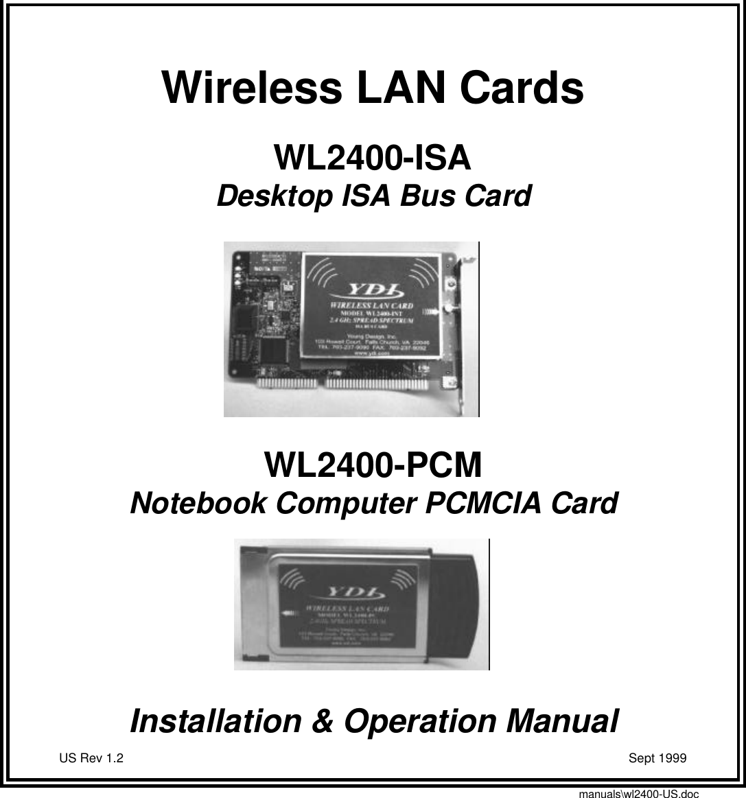
- 1. USER MANUAL FOR CARD
- 2. USER MANUAL FOR AMPLIFIER
- 3. revised amp manual
- 4. revised card manual
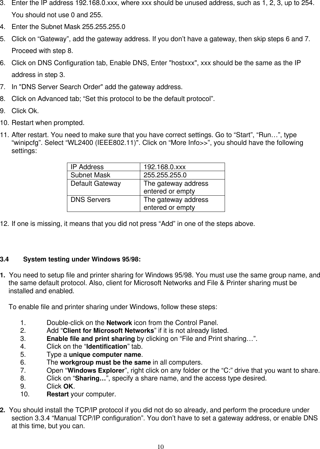
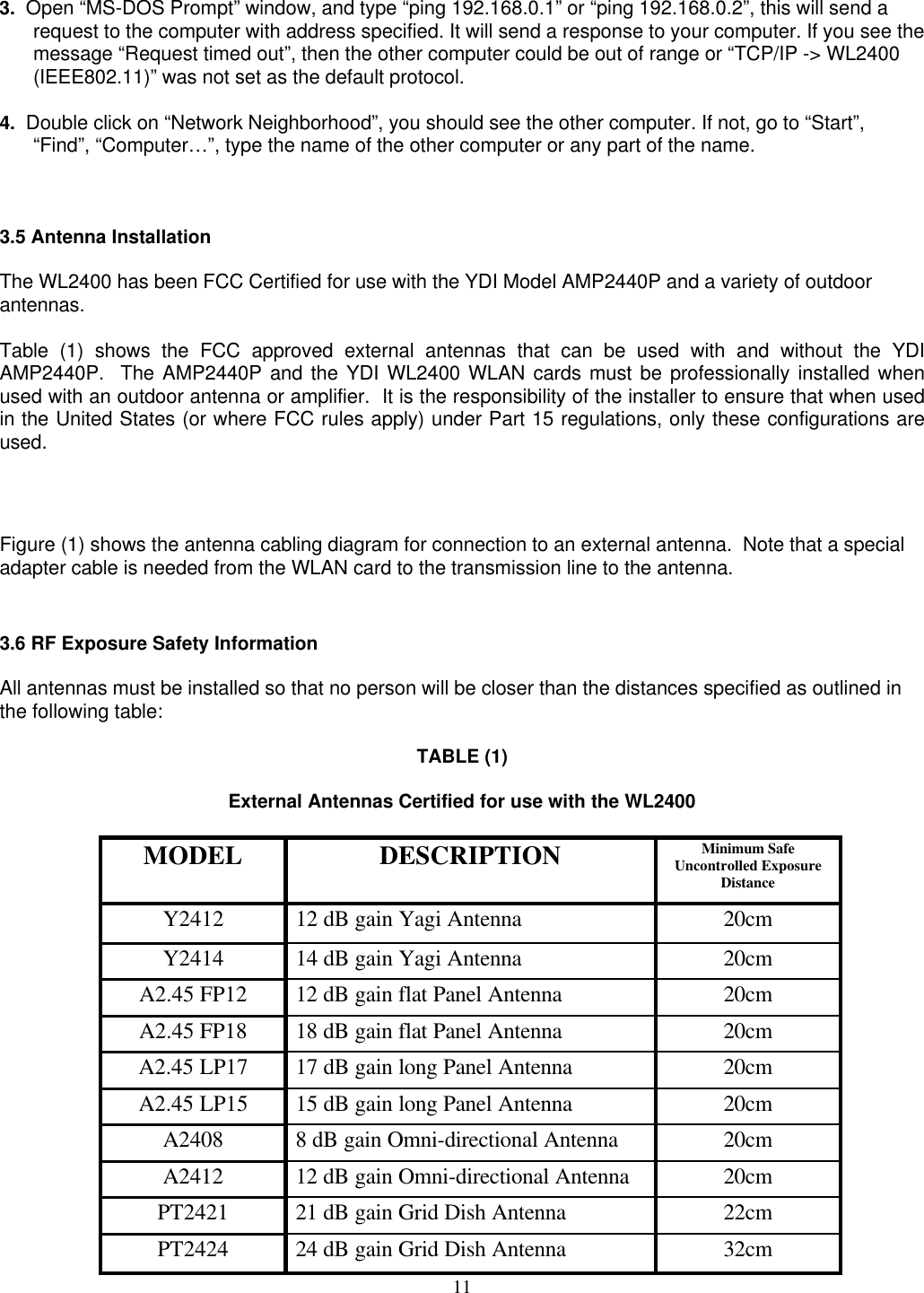
revised card manual
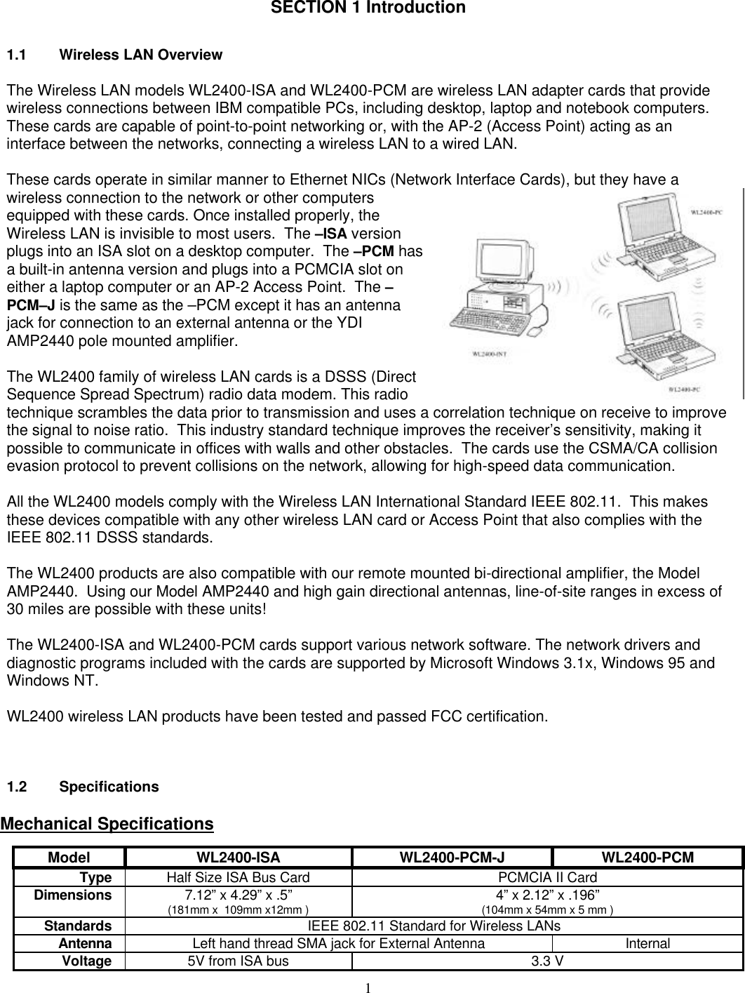
![13APPENDIX ABrief Technical Description of the IEEE 802.11 Standard802.11 is the standard for Wireless Local Area Networks (WLAN's) developed by theInstitute of Electrical and Electronics Engineers (IEEE). It can be compared to the802.3 standard for Ethernet wired LANs. The goal of this standard is to tailor a model of operation in orderto resolve compatibility issues between manufacturers of WLAN equipment manufacturers. The YDIWL2400 models comply with standard for DSSS for use with BPSK modulation at a 2 Mbps data rate.The Media Access Control (MAC) under 802.11 is composed of several functional blocks. These includemechanisms to provide contention and contention-free access control on a variety of physical layers. Thefunctions within the MAC are independent of data rates or physical characteristics.The fundamental access method of the 802.11 MAC is known as Carrier Sense Multiple Access withCollision Avoidance, or CSMA/CA. This technique works by a "listen before talk scheme". This means thata station wishing to transmit must first sense the radio channel to determine if another station istransmitting. If the medium is not busy, the transmission may proceed. The CSMA/CA scheme implementsa minimum time gap between frames from a given user. Once a frame has been sent from a giventransmitting station, that station must wait until the time gap is up to try to transmit again. Once the timehas passed, the station selects a random amount of time (called a back off interval) to wait before"listening" again to verify a clear channel on which to transmit. If the channel is still busy, another back offinterval is selected that is less than the first. This process is repeated until the waiting time approacheszero and the station is allowed to transmit. This type of multiple access ensures judicious channel sharingwhile avoiding collisions.This scheme allows automatic medium sharing between several devices with compatible radio data linkcharacteristics [i.e. the Physical Level (PHY)]. This access method is attractive because it providesspectral efficiency as well as asynchronous data transfer. Frequency Division Multiple Access (FDMA) andCode Division Multiple Access (CDMA) schemes would not be adequate because they require bandwidthused by the modulation scheme. Strict TDMA would not work well because it requires synchronization.Thus CSMA/CA, which may be thought of as a version of TDMA, is better suited to this application.The Physical Level (PHY) under 802.11 includes diffused infrared (DFIR), Direct Sequence SpreadSpectrum (DSSS), and Frequency Hopping Spread Spectrum (FHSS). Both spread spectrum techniquesare used in the 2.4 GHz band because of wide availability in many countries and lower hardware costs incomparison to the higher microwave frequencies.](https://usermanual.wiki/YDI-Wireless/WL2400-ISA.revised-card-manual/User-Guide-67639-Page-16.png)