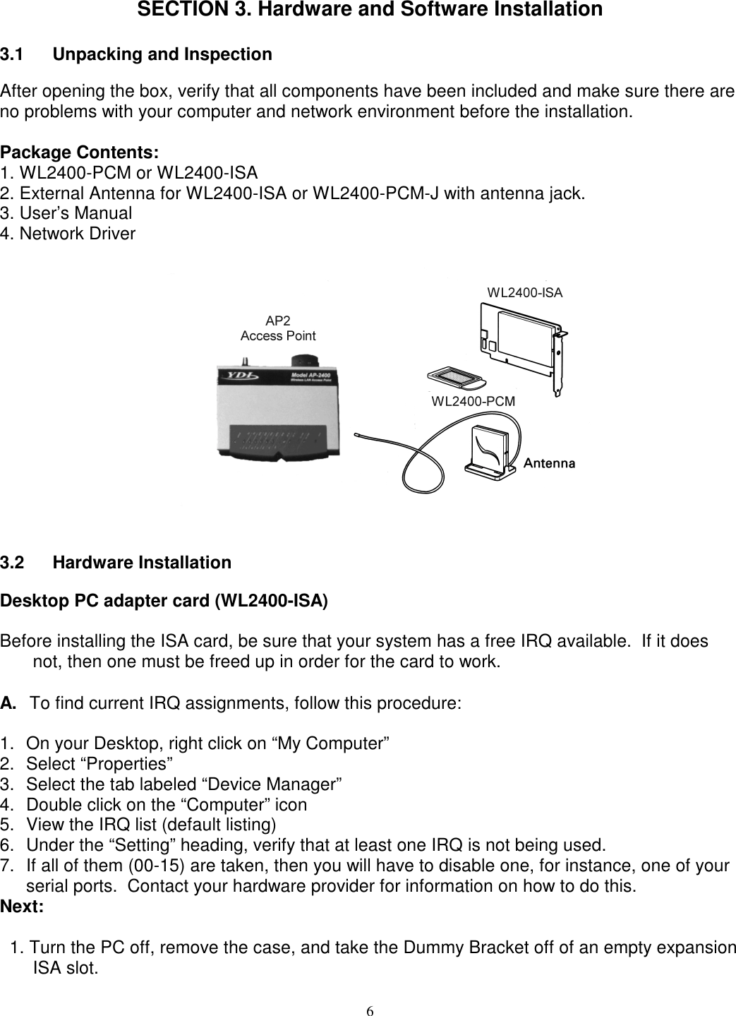
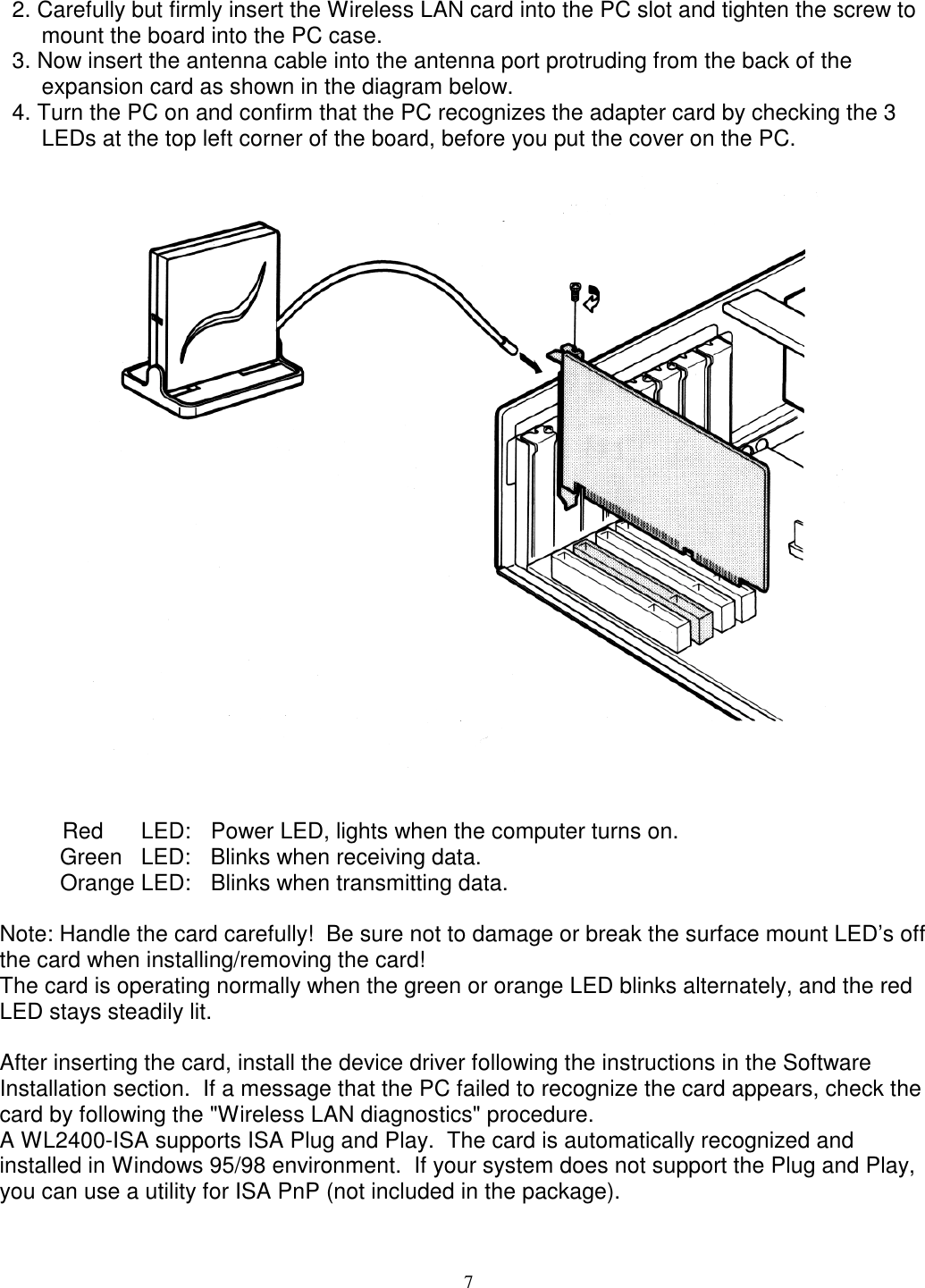
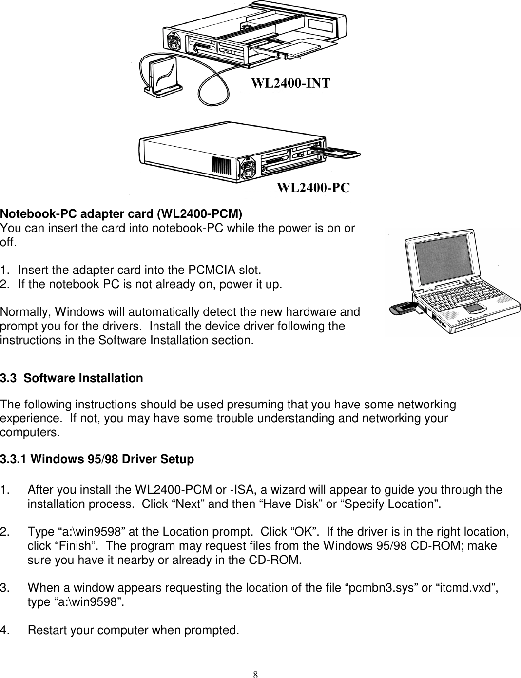
YDI Wireless WL2400-PCM User Manual for card

YDI Wireless for card

user manual for card

PreliminaryWireless LAN CardsWL2400-ISADesktop PC ISA Bus CardWL2400-PCMNotebook Computer PCMCIA CardInstallation & Operation ManualUS Rev 1.0                                                                                                                           June 1999manuals\wl2400-US.doc
NOTICEThe WL2400-ISA and WL2400-PCM have been tested and found to comply with Part 15 ofFCC regulations.Operation of these devices is subject to the following two conditions:1. This device may not cause harmful interference.2. This device must accept any interference received, including interference that mayinduce undesired operation.This device must be installed and implemented in strict accordance with the manufacturer'sinstructions.  When installing the device with our AMP2440P amplifier and outdoor gainantennas, the installation must be professionally installed to ensure compliance with FCCregulation.  YDI cannot guarantee that this device will not cause interference in a particularinstallation.  In the case that this device does cause harmful interference, the user/operatorshall promptly cease operation of the device until the threat of interference has beeneliminated.LIMITED WARRANTYYoung Design, Inc. (YDI) insures your product against defects in material and workmanshipfor a period of one year after the initial purchase.  In this period of time YDI will repair orreplace any YDI product returned to the factory, freight prepaid.The YDI warranty covers repairs or replacement (at the discretion of YDI) of the productalone.  YDI is not responsible for the cost of removal, reinstallation, or shipping to the placeof repair.  YDI will not extend or modify its warranty period as a result of repair orreplacement.YDI reserves the right to void a warranty and/or make reasonable charges for repair of theunit if the serial number sticker is missing, or the unit displays evidence of misuse, abuse,tampering or water damage.YDI is not responsible for damage to any other equipment or property, or any otherconsequential or incidental damages of any kind, whether based on contract, negligence, orstrict liability.  Maximum liability shall not in any case exceed the purchase price of the unit.Warranties give you (the buyer) specific legal rights.  You may also have other rights, whichvary, from state to state.  This warranty is only extended to purchases made in the UnitedStates of America or its possessions.All Rights Reserved.  No part or parts of this document may be reproduced, translated, storedin any electronic retrieval system, or transmitted, in any form or by any means, electronic,mechanical, photocopying, recording, or otherwise, without the prior written permission of thecopyright holder.
TABLE OF CONTENTSSECTION 1 INTRODUCTION............................................................................................................................................... 11.1 WIRELESS LAN OVERVIEW ......................................................................................................................................... 11.2 SPECIFICATIONS ........................................................................................................................................................... 11.3 DRIVERS....................................................................................................................................................................... 21.4 LED INDICATORS FOR THE MODEL WL2400-ISA ....................................................................................................... 3SECTION 2.  NETWORK APPLICATIONS......................................................................................................................... 42.1 INSTAWAVETM VS STRUCTURENETTM OPERATION ......................................................................................................... 42.2 ADVANTAGE OF INSTAWAVE........................................................................................................................................ 42.3 ADVANTAGE OF STRUCTURENET ................................................................................................................................. 52.4 ROAMING ..................................................................................................................................................................... 5SECTION 3. HARDWARE AND SOFTWARE INSTALLATION ..................................................................................... 63.1 UNPACKING AND INSPECTION....................................................................................................................................... 63.2 HARDWARE INSTALLATION .......................................................................................................................................... 63.3 SOFTWARE INSTALLATION............................................................................................................................................ 83.3.1 Windows 95/98 Driver Setup...................................................................................................................................... 83.3.2 Windows NT Driver Setup.......................................................................................................................................... 93.3.3 Network Environment Setup....................................................................................................................................... 93.3.4 TCP/IP Protocol Setup............................................................................................................................................... 93.4 SYSTEM TESTING UNDER WINDOWS 95/98:................................................................................................................ 103.5       ANTENNA INSTALLATION ............................................................................................................................................ 113.6       RF EXPOSURE SAFETY INFORMATION ........................................................................................................................ 12APPENDIX A....................................................................................................................................................................... 13TECHNICAL DESCRIPTION OF THE IEEE 802.11 STANDARD................................................................................. 13
1SECTION 1 Introduction1.1 Wireless LAN OverviewThe Wireless LAN models WL2400-ISA and WL2400-PCM are wireless LAN adapter cardsthat provide wireless connections between IBM compatible PCs, including desktop, laptop andnotebook computers.  These cards are capable of point-to-point networking or, with the AP-2(Access Point) acting as an interface between the networks, connecting a wireless LAN to awired LAN.These cards operate in similar manner to Ethernet NICs(Network Interface Cards), but they have a wirelessconnection to the network or other computers equippedwith these cards. Once installed properly, the WirelessLAN is invisible to most users.  The –ISA version plugsinto an ISA slot on a desktop computer.  The –PCM hasa built-in antenna version and plugs into a PCMCIA sloton either a laptop computer or an AP-2 Access Point.The –PCM–J is the same as the –PCM except it has anantenna jack for connection to an external antenna orthe YDI AMP2440 pole mounted amplifier.The WL2400 family of wireless LAN cards is a DSSS (Direct Sequence Spread Spectrum)radio data modem. This radio technique scrambles the data prior to transmission and uses acorrelation technique on receive to improve the signal to noise ratio.  This industry standardtechnique improves the receiver’s sensitivity, making it possible to communicate in offices withwalls and other obstacles.  The cards use the CSMA/CA collision evasion protocol to preventcollisions on the network, allowing for high-speed data communication.All the WL2400 models comply with the Wireless LAN International Standard IEEE 802.11.This makes these devices compatible with any other wireless LAN card or Access Point thatalso complies with the IEEE 802.11 DSSS standards.The WL2400 products are also compatible with our remote mounted bi-directional amplifier,the Model AMP2440.  Using our Model AMP2440 and high gain directional antennas, line-of-site ranges in excess of 30 miles are possible with these units!The WL2400-ISA and WL2400-PCM cards support various network software. The networkdrivers and diagnostic programs included with the cards are supported by Microsoft Windows3.1x, Windows 95 and Windows NT.WL2400 wireless LAN products have been tested and passed FCC certification.1.2 Specifications
2Mechanical SpecificationsModel WL2400-ISA WL2400-PCM-J WL2400-PCMType Half Size ISA Bus Card PCMCIA II CardDimensions7.12” x 4.29” x .5”(181mm x  109mm x12mm ) 4” x 2.12” x .196”(104mm x 54mm x 5 mm )Standards IEEE 802.11 Standard for Wireless LANsAntenna Left hand thread SMA jack for External Antenna InternalVoltage 5V from ISA bus 3.3 VCurrent 600 mA 290 mA (normal)Radio SpecificationsModel WL2400-ISA WL2400-PCM-J WL2400-PCMFrequency  (MHz)Channels 2412, 2417, 2422, 2427, 2432, 2437, 2442, 2447, 2452, 2457*, 2462*   1         2        3        4         5        6       7        8        9       10        11Data Rate 2 Mbps over the airModulation Direct Sequence Spread Spectrum, Differential DPSKBit Error Rate Better than 10 –8Receiver Sensitivity -85 dBm or betterTransmit Power 50 mW maximum*These frequencies cannot be used with amplifiers due to signal levels in the restricted band above 2483 MHz. Range and Coverage AreaModel WL2400-ISA WL2400-PCM-J WL2400-PCMSmall indoor antennas: Open Space:  1000 feet (300m) maxSemi Open Space: 200 feet (70m) maxClosed Space: 100 feet (30m) maxExternal Roof/Towerantennas (no amplifier): Up to 10 Miles (15 Km) with 24 dB gaingrid dish antennas ** N/AExternal Roof/Towerantennas usingModel AMP2440amplifier:UP to 30 Miles (50 Km) with 24 dB gaingrid dish antennas ** N/A        ** Unobstructed line of sight is required between the antennasSoftwareDevice Drivers NDIS for Windows95/98 and Windows NTSource code for LINUX Drivers are available as an option.1.3 Drivers Available:The following network drivers are provided:
3•  MS Windows for Workgroups 3.11• Windows 95• Windows NTAlso, the source code LINUX drivers for the stet are available free of charge fromAbsolute Value. ftp.absolval.comThe source code for ISA Card LINUX drivers is available from YDI’s web site at:www.ydi.com/download.htm1.4 LED Indicators for the Model WL2400-ISAPower: Steady red when system is powered up.TX: Blinks orange when transmitting data.RX: Blinks green when receiving data.
4SECTION 2.  Network ApplicationsThere are two types of networks used with the WL2400-ISA and WL2400-PCM: StructureNetand Instawave.  The number of computers connected, Ethernet installation, and the desirednetwork application determine the type of network.2.1 Instawavetm Vs StructureNettm OperationThe AP-2 Access Point gives you the option of operating in “Instawave” mode (default) or“StructureNet” mode.  A description of these two modes follows, as well as an explanation ofthe advantages of each compared to the other.  This information should enable you to decidewhich mode to use.  Generally, it is not a good idea to mix modes.  We recommend that allaccess points in your installation be set to the same mode.IEEE802.11 defines two modes of operation: “ad hoc” mode and “infrastructure” mode.  Theconcept behind “ad-hoc” mode is that several wireless stations such as laptops can gettogether in a local area such as a conference room and form a wireless network together.This would enable the sharing of documents and collaborative working using applications suchas Microsoft’s NetMeeting.  In ad-hoc mode all the operations are peer to peer, but cannotcommunicate with an access point.Infrastructure mode requires the use of an access point.  In Infrastructure mode, all wirelesscommunication is between a station and an access point.  There must be an operationalaccess point in the vicinity for a station to communicate.  Even if there are two wirelessstations, they cannot communicate directly in the manner described for “ad-hoc” networks;they must communicate with each other via the access point.The AP-2 has a mode that has the attributes of “ad-hoc” operation, but also allows you to usethe Access Point to communicate with a wired LAN.  This mode is called “InstawaveTM ” and isthe default mode of operation.2.2 Advantage of InstawaveInstawave is very easy to set up.  All the stations on a specific radio channel form a network ifthey are within range of each other.  The channel can be specified in the access point and onthe PCs or laptops. The default channel is 10.Regardless of how many access points and stations there are in an area, they willautomatically form a network.  The access points may be attached to the same LAN or theymay be on different LAN segments.  The advantage of Instawave is that the most directcommunication path is taken automatically.  If two stations wish to communicate peer-to-peerthey can do so.  If the station wishes to communicate with a server on the LAN the correctaccess point will accept the data and forward it to the LAN.  If there are two or more accesspoints attached to the same LAN, the access points will determine which access point is usedautomatically — the user does not need to intervene.
5Instawave is a good choice for small networks that need maximum flexibility and simplicity.  Touse Instawave you must configure the AP-2 with “mode: Instawave” and set the Channel onthe remote stations to the same number as on the AP-2.2.3 Advantage of StructureNetWhen StructureNet is enabled each wireless station must associate with a single access point.That access point is responsible for receiving and sending all data to the station.  A stationcannot be associated with more than one access point at a time.  The disadvantage of this isthat peer-to-peer communication requires that a message be sent twice — once to the accesspoint and a second time to the destination station.  However, the advantage of StructureNet isthat the MIS manager can have more control over the connections because they pass througha single access point.  Also because each station associates with only one access point at atime, it is possible for the station to dynamically change radio channels when switching fromone access point to another.  This is known as “multi-channel” roaming.In larger networks where the manager wishes to have more control over connections and maywish to implement a radio cell organization in which each radio cell is on a different radiochannel, StructureNet TM is a good choice.If this is your first experience with the Access Point we recommend that you use Instawave forinitial testing and, if required, change to StructureNet once you are satisfied with the operationof the wireless network.To use StructureNet you must configure the AP-2 with “mode: StructureNet” and configurethe mobile stations with the same ESSID value as on the AP-2.2.4 RoamingWith multiple LAN Access Points installed, a user can roam from cell to cell and maintain awireless connection to the server.  For example, a user at location A will be served by cell site1.  At location B, either cell 1 or 2 will serve him.  Likewise, when the user roams out of cellsite 2, he will be picked up by cell site 3.
6SECTION 3. Hardware and Software Installation3.1 Unpacking and InspectionAfter opening the box, verify that all components have been included and make sure there areno problems with your computer and network environment before the installation.Package Contents:1. WL2400-PCM or WL2400-ISA2. External Antenna for WL2400-ISA or WL2400-PCM-J with antenna jack.3. User’s Manual4. Network Driver3.2 Hardware InstallationDesktop PC adapter card (WL2400-ISA)Before installing the ISA card, be sure that your system has a free IRQ available.  If it doesnot, then one must be freed up in order for the card to work.A.  To find current IRQ assignments, follow this procedure:1.  On your Desktop, right click on “My Computer”2. Select “Properties”3.  Select the tab labeled “Device Manager”4.  Double click on the “Computer” icon5.  View the IRQ list (default listing)6.  Under the “Setting” heading, verify that at least one IRQ is not being used.7.  If all of them (00-15) are taken, then you will have to disable one, for instance, one of yourserial ports.  Contact your hardware provider for information on how to do this.Next:  1. Turn the PC off, remove the case, and take the Dummy Bracket off of an empty expansionISA slot.
7  2. Carefully but firmly insert the Wireless LAN card into the PC slot and tighten the screw tomount the board into the PC case.  3. Now insert the antenna cable into the antenna port protruding from the back of theexpansion card as shown in the diagram below.  4. Turn the PC on and confirm that the PC recognizes the adapter card by checking the 3LEDs at the top left corner of the board, before you put the cover on the PC.Red      LED: Power LED, lights when the computer turns on.Green   LED: Blinks when receiving data.Orange LED: Blinks when transmitting data.Note: Handle the card carefully!  Be sure not to damage or break the surface mount LED’s offthe card when installing/removing the card!The card is operating normally when the green or orange LED blinks alternately, and the redLED stays steadily lit.After inserting the card, install the device driver following the instructions in the SoftwareInstallation section.  If a message that the PC failed to recognize the card appears, check thecard by following the "Wireless LAN diagnostics" procedure.A WL2400-ISA supports ISA Plug and Play.  The card is automatically recognized andinstalled in Windows 95/98 environment.  If your system does not support the Plug and Play,you can use a utility for ISA PnP (not included in the package).
8Notebook-PC adapter card (WL2400-PCM)You can insert the card into notebook-PC while the power is on oroff.1.  Insert the adapter card into the PCMCIA slot.2.  If the notebook PC is not already on, power it up.Normally, Windows will automatically detect the new hardware andprompt you for the drivers.  Install the device driver following theinstructions in the Software Installation section.3.3  Software InstallationThe following instructions should be used presuming that you have some networkingexperience.  If not, you may have some trouble understanding and networking yourcomputers.3.3.1 Windows 95/98 Driver Setup1.  After you install the WL2400-PCM or -ISA, a wizard will appear to guide you through theinstallation process.  Click “Next” and then “Have Disk” or “Specify Location”.2.  Type “a:\win9598” at the Location prompt.  Click “OK”.  If the driver is in the right location,click “Finish”.  The program may request files from the Windows 95/98 CD-ROM; makesure you have it nearby or already in the CD-ROM.3.  When a window appears requesting the location of the file “pcmbn3.sys” or “itcmd.vxd”,type “a:\win9598”.4.  Restart your computer when prompted.
93.3.2 Windows NT Driver Setup1.  Click “Start”, “Settings”, “Control Panel”.2.  Double click the “Network” icon.3.  Click the “Adapters” tab, and click “Select Network Adapter”, then “Have Disk”.4.  Insert the provided disk, and specify the path “a:\windownt” then click “OK”.5.  When the program finds the driver, click “OK” at the next window.3.3.3 Network Environment Setup1.  Click “Start”, “Settings”, “Control Panel”.2.  Double click the “Network” icon.3.  Click on “WL2400 (IEEE 802.11)”, “Properties”.4.  Click on “Operating Mode”.5.  Select “Instawave”, and set the channel number to the one used by other wireless stationsor Access Points that you want to communicate with.3.3.4 TCP/IP Protocol SetupIf you wish to use another protocol such as IPX/SPX, then skip this section.Installing TCP/IP1.  Click “Start”, “Settings”, “Control Panel”.2.  Double click the “Network” icon.3.  You should see the line “TCP/IP -> WL2400 (IEEE 802.11)”.4.  If not, then click “Add…”, “Protocol”, “Microsoft”, “TCP/IP”, “Ok”.Manual TCP/IP configuration:If you have an access point that is attached to a LAN, which has a DHCP (Dynamic HostConfiguration Protocol) server then you don’t have to do anything. Windows will automaticallyrequest configuration information from that server, such as an IP address, DNS serversettings. The access point will forward DHCP messages and any broadcast messages.If you don’t have a DHCP server, then you have to assign the configuration manually.
10There are IP addresses that are reserved for private LAN use. No one in the Internet usesthese addresses. They begin with 192.168.0.1 and end with 192.168.254.254. We will usethem here.If you have a gateway to the Internet, such as a stand-alone router, or a computer with a proxyserver or modem sharing software, then you will need the gateway address of that computer. Ifyou don’t have a gateway, then skip steps 5, 6 and 7.To specify the configuration manually, do the following:1.  From Control Panel, Network, click on "TCP/IP -> WL2400 (IEEE802.11)", “Properties”.2.  Click on “IP Address”, “Specify IP Address”.3.  Enter the IP address 192.168.0.xxx, where xxx should be unused address, such as 1, 2, 3,up to 254. You should not use 0 and 255.4.  Enter the Subnet Mask 255.255.255.05.  Click on “Gateway”, add the gateway address. If you don’t have a gateway, then skip steps6 and 7. Proceed with step 8.6.  Click on DNS Configuration tab, Enable DNS, Enter "hostxxx", xxx should be the same asthe IP address in step 3.7.  In "DNS Server Search Order" add the gateway address.8.  Click on Advanced tab; “Set this protocol to be the default protocol”.9. Click Ok.10. Restart when prompted.11. After restart. You need to make sure that you have correct settings. Go to “Start”, “Run…”,type “winipcfg”. Select “WL2400 (IEEE802.11)". Click on “More Info>>”, you should havethe following settings:IP Address 192.168.0.xxxSubnet Mask 255.255.255.0Default Gateway The gateway addressentered or emptyDNS Servers The gateway addressentered or empty12. If one is missing, it means that you did not press “Add” in one of the steps above.3.4 System testing under Windows 95/98:
111.  You need to setup file and printer sharing for Windows 95/98. You must use the samegroup name, and the same default protocol. Also, client for Microsoft Networks and File &Printer sharing must be installed and enabled.To enable file and printer sharing under Windows, follow these steps:1.  Double-click on the Network icon from the Control Panel.2. Add “Client for Microsoft Networks” if it is not already listed.3.  Enable file and print sharing by clicking on “File and Print sharing…”.4.  Click on the “Identification” tab.5. Type a unique computer name.6. The workgroup must be the same in all computers.7. Open “Windows Explorer”, right click on any folder or the “C:” drive that youwant to share.8.  Click on “Sharing…”, specify a share name, and the access type desired.9. Click OK.10.  Restart your computer.2.  You should install the TCP/IP protocol if you did not do so already, and perform theprocedure under section 3.3.4 “Manual TCP/IP configuration”. You don’t have to set agateway address, or enable DNS at this time, but you can.3.  Open “MS-DOS Prompt” window, and type “ping 192.168.0.1” or “ping 192.168.0.2”, thiswill send a request to the computer with address specified. It will send a response to yourcomputer. If you see the message “Request timed out”, then the other computer could beout of range or “TCP/IP -> WL2400 (IEEE802.11)” was not set as the default protocol.4.  Double click on “Network Neighborhood”, you should see the other computer. If not, go to“Start”, “Find”, “Computer…”, type the name of the other computer or any part of the name.3.5 Antenna InstallationThe WL2400 has been FCC Certified for use with the YDI Model AMP2440P and a variety ofoutdoor antennas.Table (1) shows the FCC approved external antennas that can be used with and without theYDI AMP2440P.  The AMP2440P and the YDI WL2400 WLAN cards must be professionallyinstalled when used with an outdoor antenna or amplifier.  It is the responsibility of the installerto ensure that when used in the United States (or where FCC rules apply) under Part 15regulations, only these configurations are used.Figure (1) shows the antenna cabling diagram for connection to an external antenna.  Notethat a special adapter cable is needed from the WLAN card to the transmission line to theantenna.
123.6 RF Exposure Safety InformationAll antennas must be installed so that no person will be closer than the distances specified asoutlined in the following table:TABLE (1)External Antennas Certified for use with the WL2400MODEL DESCRIPTION Minimum SafeUncontrolledExposure DistanceMinimum SafeControlled ExposureDistanceY2412 12 dB gain Yagi Antenna 20cm 20cmY2414 14 dB gain Yagi Antenna 20cm 20cmA2.45 FP12 12 dB gain flat Panel Antenna 20cm 20cmA2.45 FP18 18 dB gain flat Panel Antenna 20cm 20cmA2.45 LP17 17 dB gain long Panel Antenna 20cm 20cmA2.45 LP15 15 dB gain long Panel Antenna 20cm 20cmA2408 8 dB gain Omni-directionalAntenna 20cm 20cmA2412 12 dB gain Omni-directionalAntenna 20cm 20cmPT2421 21 dB gain Grid Dish Antenna 22cm 20cmPT2424 24 dB gain Grid Dish Antenna 32cm 20cmUncontrolled exposure distance is where the power density is 1mW/cm2.  Controlled exposuredistances is where the power density is 5mW/cm2 .  The antennas must be installed such thatthere will be no person closer than the specified distances in front of directional antennas ordirectly beside the Omni antennas.Note: 20cm is the minimum distance regardless of what the actual calculation of the powerdensity shows.
13APPENDIX ABrief Technical Description of the IEEE 802.11 Standard802.11 is the standard for Wireless Local Area Networks (WLAN's) developed by theInstitute of Electrical and Electronics Engineers (IEEE). It can be compared to the802.3 standard for Ethernet wired LANs. The goal of this standard is to tailor a model ofoperation in order to resolve compatibility issues between manufacturers of WLAN equipmentmanufacturers.  The YDI WL2400 models comply with standard for DSSS for use with BPSKmodulation at a 2 Mbps data rate.The Media Access Control (MAC) under 802.11 is composed of several functional blocks.These include mechanisms to provide contention and contention-free access control on avariety of physical layers. The functions within the MAC are independent of data rates orphysical characteristics.The fundamental access method of the 802.11 MAC is known as Carrier Sense MultipleAccess with Collision Avoidance, or CSMA/CA. This technique works by a "listen before talkscheme". This means that a station wishing to transmit must first sense the radio channel todetermine if another station is transmitting. If the medium is not busy, the transmission mayproceed. The CSMA/CA scheme implements a minimum time gap between frames from agiven user. Once a frame has been sent from a given transmitting station, that station mustwait until the time gap is up to try to transmit again. Once the time has passed, the stationselects a random amount of time (called a back off interval) to wait before "listening" again toverify a clear channel on which to transmit. If the channel is still busy, another back off intervalis selected that is less than the first. This process is repeated until the waiting time approacheszero and the station is allowed to transmit. This type of multiple access ensures judiciouschannel sharing while avoiding collisions.This scheme allows automatic medium sharing between several devices with compatible radiodata link characteristics [i.e. the Physical Level (PHY)]. This access method is attractivebecause it provides spectral efficiency as well as asynchronous data transfer. FrequencyDivision Multiple Access (FDMA) and Code Division Multiple Access (CDMA) schemes wouldnot be adequate because they require bandwidth used by the modulation scheme.  StrictTDMA would not work well because it requires synchronization. Thus CSMA/CA, which maybe thought of as a version of TDMA, is better suited to this application.The Physical Level (PHY) under 802.11 includes diffused infrared (DFIR), Direct SequenceSpread Spectrum (DSSS), and Frequency Hopping Spread Spectrum (FHSS). Both spreadspectrum techniques are used in the 2.4 GHz band because of wide availability in manycountries and lower hardware costs in comparison to the higher microwave frequencies.

Navigation menu