YDI Wireless WL2400-PCM User Manual AMP2440P FCC
YDI Wireless AMP2440P FCC
UserManual.wiki
>
YDI Wireless
>
WL2400-PCM User Manual
>
revised amp manual
Contents
1.
user manual for card
2.
user manual for amp
3.
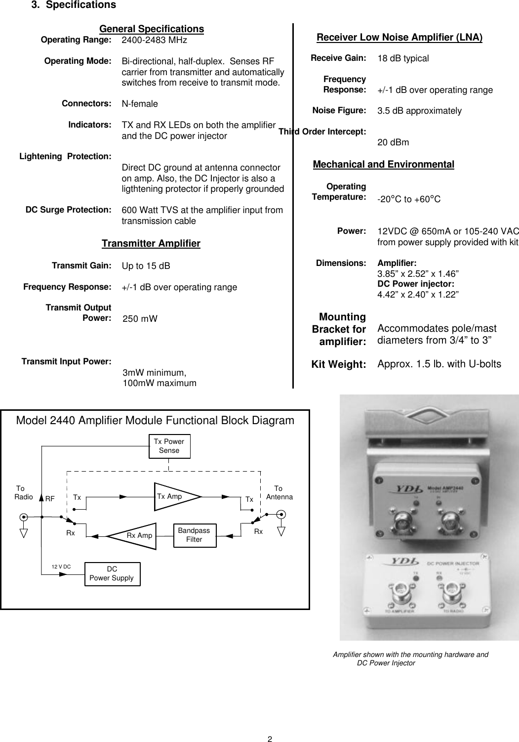
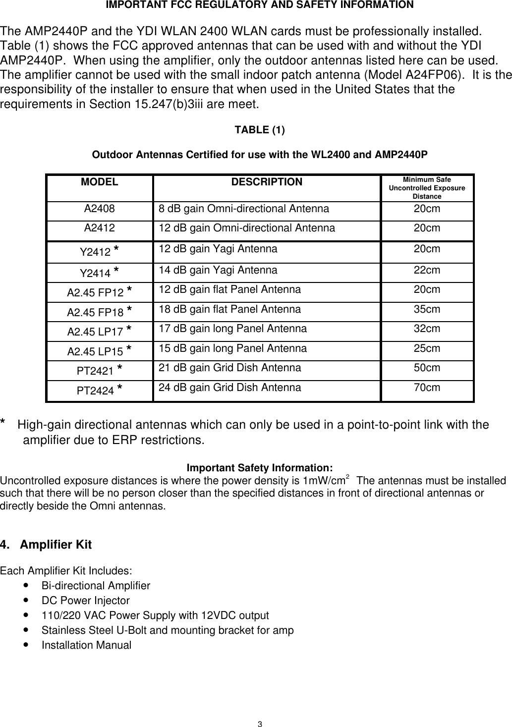
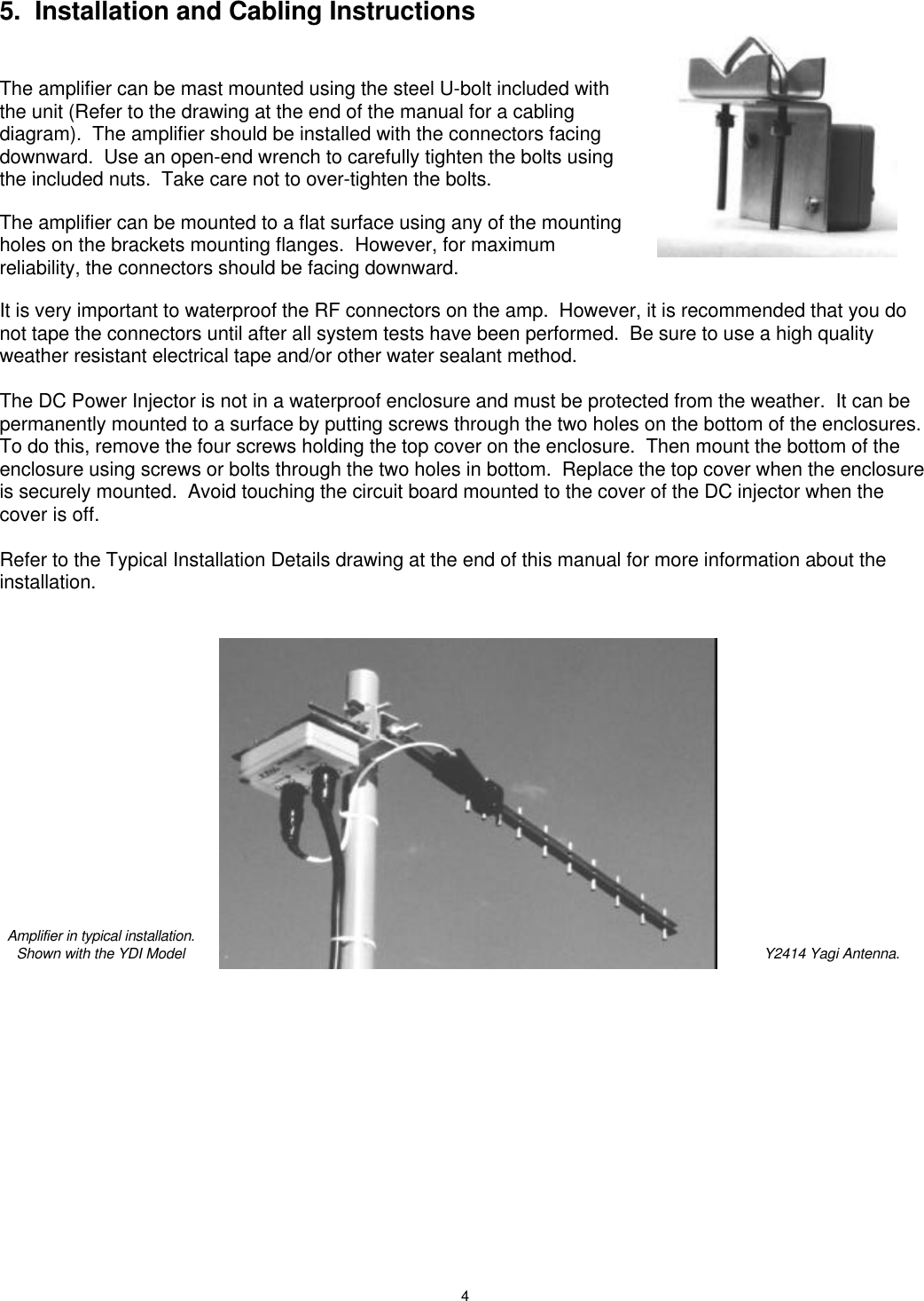
revised amp manual
4.
revised card manual
revised amp manual
Navigation menu
Upload a User Manual
Namespaces
Wiki Guide
HTML
PDF
Info
Views
User Manual
Discussion / Help
Navigation