YDI Wireless WL2400-PCM User Manual for amp
YDI Wireless for amp
Contents
- 1. user manual for card
- 2. user manual for amp
- 3. revised amp manual
- 4. revised card manual
user manual for amp
Prelimimary
Model AMP2440P
REMOTE BI-DIRECTIONAL POWER
AMPLIFIERS FOR 2.4 GHz
User and Installation Manual
Version 1.0P June 1999
\manuals\AMP2440P-FCC.doc

IMPORTANT SAFETY INFORMATION
Connecting the RF output of a radio modem transmitter to a high gain antenna will result
in concentrated signal level near the antenna. The field strength radiated by these
antennas, when connected to a transmitting Model 2400 Radio Modem with AMP2440P,
may exceed FCC mandated RF exposure limits. FCC rules require professional
installation of theses antennas in such a way that the general public will not be closer than
70 cm from the radiating aperture of any of these antennas. End users of these systems
must also be informed of this safety distance requirement.
LIMITED WARRANTY
Young Design, Inc. (YDI) warrants that your device is free of defects in material and workmanship
for a period of one year after initial purchase. YDI will repair or replace any YDI product returned
to the factory freight prepaid within one year of the purchase date.
The YDI warranty covers repairs or replacement (at YDI’s option) of the product only. YDI is not
responsible for the cost of removal, reinstallation, or shipping to the place of repair. YDI does not
extend or modify its warranty period as a result of repair or replacement.
YDI reserves the right to void a warranty and/or bill reasonable charges for repair of a unit if the
warranty seal is broken or the unit displays evidence of misuse, abuse, or tampering.
YDI is not responsible for damage to any other equipment or property, or any other consequential
or incidental damages of any kind, whether based on contract, negligence, or strict liability.
Maximum liability shall not in any case exceed the purchase price of the unit.
Warranties give you (the buyer) specific legal rights. You may also have other rights which vary
from state to state. This warranty is only extended to purchases made in the United States of
America or its possessions.
All Rights Reserved. No part or parts of this document may be reproduced, translated, stored
in any electronic retrieval system, or transmitted, in any form or by any means, electronic,
mechanical, photocopying, recording, or otherwise, without the prior written permission of the
copyright holder.
WARRANTY NOTICE
The AMP2440P warranty is null and void if any of the following occurs:
1. The amplifier is opened.
2. The antenna connections are not properly waterproofed.
3. The amplifier is operated with no antenna attached to the antenna connector.
2
TABLE OF CONTENTS
1. DESCRIPTION.....................................................................................................................................................................1
2. AMPLIFIER FEATURES....................................................................................................................................................1
3. SPECIFICATIONS...............................................................................................................................................................2
4. AMPLIFIER KIT..................................................................................................................................................................3
5. INSTALLATION AND CABLING INSTRUCTIONS ......................................................................................................4
6. AMPLIFIER CONNECTIONS AND INDICATORS........................................................................................................5
7. DC POWER INJECTOR CONNECTIONS AND INDICATORS...................................................................................5
8. POWER SUPPLY.................................................................................................................................................................6
9. OPERATION.........................................................................................................................................................................6
TABLE A - CONVERSIONS FROM DBM TO WATTS ......................................................................................................7
TABLE B - TYPICAL CABLE ATTENUATION VALUES .................................................................................................7
TABLE C - AMP2440P TYPICAL INSTALLATION ...........................................................................................................9
1
1. Description
The AMP2440P is a bi-directional amplifier designed for extending the range of 2.4 GHz
wireless LAN cards. The Model AMP2440P amplifier is intended only for use with the YDI
Model WL2400-PCM and the WL2400-ISA 2.4 GHz Direct Sequence Spread Spectrum
Wireless LAN cards. The units provide transmit power amplification as well as receive signal
gain. The amplifier is installed right at the antenna’s feed point, providing maximum
effectiveness of transmit power. This has the effect of compensating for signal loss in the
transmitter cable to the antenna. Likewise, the Low Noise Amplifier (LNA) in the AMP2440P
boosts the receive signal right at the antenna prior to experiencing the loss in the transmission
cable to the radio. This gain also overcomes the losses in the transmission cable between the
amplifier and the radio. In fact, use of the amp will actually increase the receiver sensitivity by
a few dB! The ultimate result is the best possible noise figure and maximum receiver
sensitivity.
The amplifier is completely weatherproof and can be bolted to the antenna mast or tower leg
using the U-bolt included. The connectors face down so that gravity will drain all water away
from the amplifier enclosure. This will prevent water from settling on the face of the unit.
Likewise, since the LEDs are also facing downward they can be checked for operation from
the bottom of the mast.
DC Power to the amplifier is supplied through the transmission cable, using an indoor power
supply and DC Injector. The amplifier unit also contains its own integral lightning protection
and DC surge protection. Likewise, the DC Power Injector connected to the WLAN card offers
built-in lightening if properly grounded.
Full output power of 250 mW is achieved with only 20 mW (+10 dBm) input to the amplifier.
2. Amplifier Features
• Transmit input levels from 3mW to 100mW
• Up to 15dB transmitter power gain
• 18dB receive gain
• Low Noise Preamp
• Weatherproof Cast Aluminum Case that is Mast Mountable
• Mounting hardware that will accommodate mast diameters from 3/4” thru 3”
• Polyurethane gasket for watertight seal on amplifier
• DC Power carried up through the transmission cable
• Power and Transmit LEDs on both the amp and the DC power injector
• Built-in Lightening and DC Surge Protection
• Heavy Duty “N” Connectors
• One Year Warranty
• Made in the U.S.A.
2
3. Specifications
General Specifications
Operating
Range: 2400-2483 MHz
Operating Mode: Bi-directional, half-duplex. Senses
RF carrier from transmitter and
automatically switches from receive
to transmit mode.
Connectors: N-female
Indicators: TX and RX LEDs on both the
amplifier and the DC power injector
Lightening
Protection: Direct DC ground at antenna
connector on amp. Also, the DC
Injector is also a ligthtening
protector if properly grounded
DC Surge
Protection: 600 Watt TVS at the amplifier input
from transmission cable
Transmitter Amplifier
Transmit Gain: Up to 15 dB
Frequency
Response:
Transmit Output
Power:
+/-1 dB over operating range
250 mW
Transmit Input
Power: 3mW minimum,
100mW maximum
Receiver Low Noise Amplifier (LNA)
Receive Gain: 18 dB typical
Frequency
Response: +/-1 dB over operating range
Noise Figure: 3.5 dB approximately
Third Order
Intercept: 20 dBm
Mechanical and Environmental
Operating
Temperature: -20°C to +60°C
Power: 12VDC @ 650mA or 105-240
VAC from power supply provided
with kit
Dimensions: Amplifier:
3.85” x 2.52” x 1.46”
DC Power injector:
4.42” x 2.40” x 1.22”
Mounting Bracket
for amplifier: Accommodates pole/mast
diameters from 3/4” to 3”
Kit Weight: Approx. 1.5 lb. with U-bolts
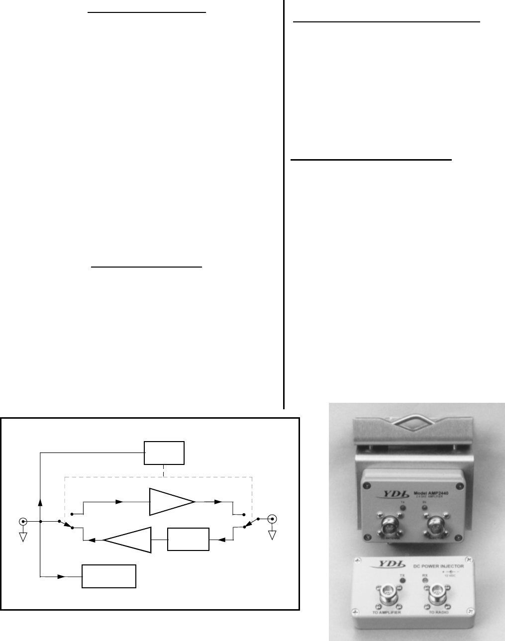
Amplifier shown with the mounting hardware and
DC Power Injector
Tx Power
Sense
To
Radio
DC
Power Supply
12 V DC
Rx
Tx Tx Amp
Rx Amp Bandpass
Filte
r
Tx
To
A
ntenna
Model 2440 Amplifier Module Functional Block Diagram
RF
Rx

3
IMPORTANT FCC REGULATORY INFORMATION
The AMP2440P and the YDI WLAN 2400 WLAN cards must be professionally installed. Table
(1) shows the FCC approved antennas that can be used with and without the YDI AMP2440P.
It is the responsibility of the installer to ensure that when used in the United States (or where
FCC rules apply) under Part 15 regulations, only these configurations can be used.
TABLE (1)
Antennas Certified for use with the WL2400 and AMP2440P
MODEL DESCRIPTION Minimum Safe
Uncontrolled
Exposure Distance
Minimum Safe
Controlled
Exposure Distance
Y2412 12 dB gain Yagi Antenna 20cm 20cm
Y2414 14 dB gain Yagi Antenna 22cm 20cm
A2.45 FP12 12 dB gain flat Panel Antenna 20cm 20cm
A2.45 FP18 18 dB gain flat Panel Antenna 35cm 20cm
A2.45 LP17 17 dB gain long Panel Antenna 32cm 20cm
A2.45 LP15 15 dB gain long Panel Antenna 25cm 20cm
A2408 8 dB gain Omni-directional
Antenna 20cm 20cm
A2412 12 dB gain Omni-directional
Antenna 20cm 20cm
PT2421 21 dB gain Grid Dish Antenna 50cm 22cm
PT2424 24 dB gain Grid Dish Antenna 70cm 32cm
Uncontrolled exposure distances is where the power density is 1mW/cm2 . Controlled
exposure distances is where the power density is 5mW/cm2. The antennas must be installed
such that there will be no person closer than the specified distances in front of directional
antennas or directly beside the Omni antennas.
Note: 20cm is the minimum distance regardless of what the actual calculation of the density
shows.
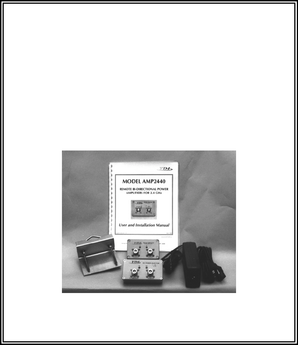
4. Amplifier Kit
Each Amplifier Kit Includes:
• Bi-directional Amplifier
• DC Power Injector
• 110/220 VAC Power Supply with 12VDC output
• Stainless Steel U-Bolt and mounting bracket for amp
• Installation Manual
4
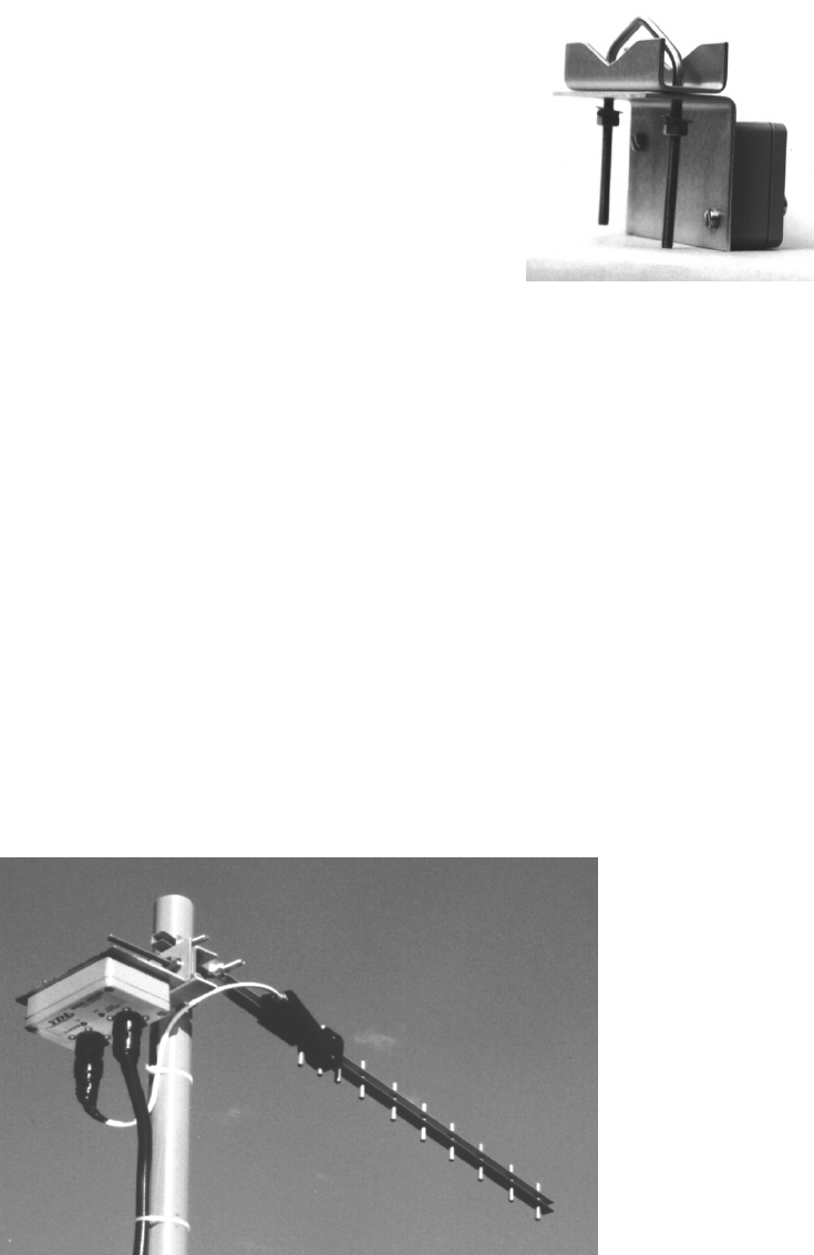
5. Installation and Cabling Instructions
The amplifier can be mast mounted using the steel U-bolt
included with the unit (Refer to the drawing at the end of the
manual for a cabling diagram). The amplifier should be installed
with the connectors facing downward. Use an open-end wrench
to carefully tighten the bolts using the included nuts. Take care
not to over-tighten the bolts.
The amplifier can be mounted to a flat surface using any of the mounting holes on the
brackets mounting flanges. However, for maximum reliability, the connectors should be facing
downward.
It is very important to waterproof the RF connectors on the amp. However, it is recommended
that you do not tape the connectors until after all system tests have been performed. Be sure
to use a high quality weather resistant electrical tape and/or other water sealant method.
The DC Power Injector is not in a waterproof enclosure and must be protected from the
weather. It can be permanently mounted to a surface by putting screws through the two holes
on the bottom of the enclosures. To do this, remove the four screws holding the top cover on
the enclosure. Then mount the bottom of the enclosure using screws or bolts through the two
holes in bottom. Replace the top cover when the enclosure is securely mounted. Avoid
touching the circuit board mounted to the cover of the DC injector when the cover is off.
Refer to the Typical Installation Details drawing at the end of this manual for more information
about the installation.
Amplifier in typical installation.
Shown with the YDI Model Y2414 Yagi Antenna.
5
6. Amplifier Connections and Indicators
Transmit LED:This LED glows RED in transmit mode indicating that RF power is
applied to the amplifier from the radio.
Receive LED:This LED glows GREEN in the receive mode when DC power is
applied to the amplifier and is off when transmitting.
DC Injector
Connection: This “N” Female connector is connected to the DC Power Injector
via the transmission cable.
Antenna Connection: This “N” Female connector connects to the antenna with a short
length of coax cable.
7. DC Power Injector Connections and Indicators
A DC Power Injector is an in-line device which “injects” the DC power necessary to operate the
amplifier onto a transmission line. This allows the cable to carry both RF signals and DC
power to the mast mounted amplifier.
Transmit LED: This LED glows RED when the pole mounted amplifier goes into
the transmit mode. The Remote Transmit LED is driven by unique
circuitry, which actually detects changes in the DC current
traveling through the transmission line to the amplifier.
Receive LED: This LED glows GREEN when DC power is applied to the
amplifier and it is in the receive mode. When toggling between
transmit and receive this LED will glow slightly dimmer.
To Radio Connection: This “N” Female connector is connected to the radio modem via a
short jumper cable.
To Amplifier
Connection: This “N” Female connector connects to the amplifier on the mast
via the transmission line.
12 VDC: This is the DC power input for the injector and is a standard 2.1
mm barrel jack. +12VDC should be applied with center positive.
6
8. Power Supply
The AMP2440P comes with a power supply that have standard 2.1 mm barrel plugs (which
are configured as positive (+) tip and negative ( - ) outer conductor). Although normally
supplied with a power supply, any regulated 12 Volt DC 1 amp supply can be used. The
power supply provided with the kit can be used with 110 or 240 VAC power.
9. Operation
The unit operates automatically and there are no user adjustments.
These modems “ping-pong” back and forth between transmit and receive so quickly during
normal operation that both the TX and RX LEDs will appear to be lit simultaneously. In fact,
they are turning on and off so quickly that they appear to be on all the time. You can tell how
quickly one of these LEDs are turning on and off by their brightness. Their glow will be slightly
dimmer when they are off.
7
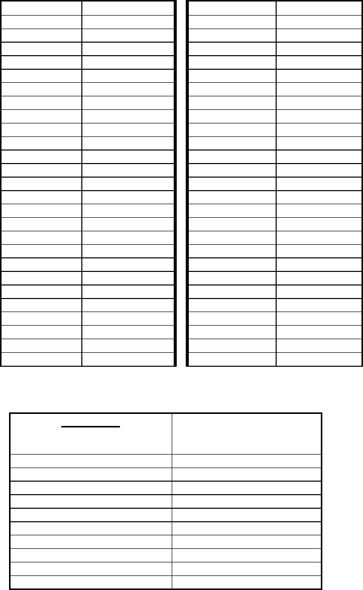
Table A - Conversions from dBm to Watts
dBm Watts dBm Watts
0 1.0 mW 26 398 mW
1 1.3 mW 27 500 mW
2 1.6 mW 28 630 mW
3 2.0 mW 29 800 mW
4 2.5 mW 30 1.0 W
5 3.2 mW 31 1.3 W
6 4.0 mW 32 1.6 W
7 5.0 mW 33 2.0 W
8 6 mW 34 2.5 W
9 8 mW 35 3.0 W
10 10 mW 36 4.0 W
11 13 mW 37 5.0 W
12 16 mW 38 6.0 W
13 20 mW 39 8.0 W
14 25 mW 40 10 W
15 32 mW 41 13 W
16 40 mW 42 16 W
17 50 mW 43 20 W
18 63 mW 44 25 W
19 79 mW 45 32 W
20 100 mW 46 44 W
21 126 mW 47 58W
22 158 mW 48 64 W
23 200 mW 49 64 W
24 250 mW 50 100 W
25 316 mW
Table B - Typical Cable Attenuation Values
Cable Type Attenuation per 100 ft
(dB)
at 2.4 GHz
Belden 9913 8.0
LMR 200 16.8
LMR 240 12.9
LMR 400 6.8
LMR 600 4.4
1/2 “LDF 3.9
1/2” Superflex 6.1
3/8” LDF 5.9
3/8” Superflex 6.8
1/4” Superflex 9.8
These values are approximate. Check with cable manufacturers for exact
specifications.
8
9
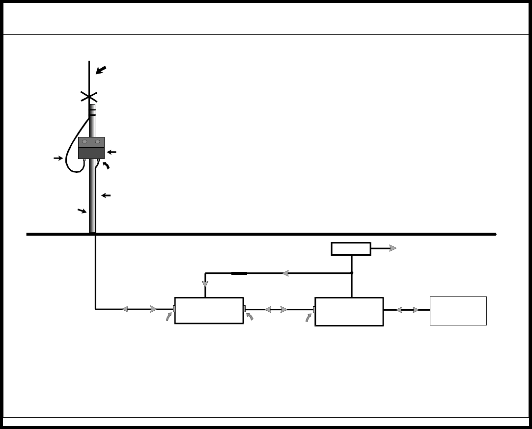
Table C - AMP2440P Typical Installation
TYPICAL INSTALLATION DETAILS
If the customer does the installation, YDI will provide:
A
ntenna, pole mounted amp, DC injector, DC power supply and
the Model 2400 radio modem, if ordered.
The radio installer should provide: Mast, cable from antenna to amp, transmission line from the amp to the
DC injector, short cable from the DC injector to the radio modem and
the RS232 cable. However, YDI can also provide any of the cables,
if desired.
DC POWER
INJECTOR Model 2400
Radio Modem PC
,
Router
,
PLC
,
etc.
RS232 cable
Short len
g
th of RG58/U
(
CAB-RPNM-12“
)
RF + DC
Choke
110/220 VAC
DC P.S.
N-male
N-male RP-TNC male
ANTENNA
Omni-directional (shown), or
Grid Dish Yagi Antennas (not shown)
AMP2440
(
mounted to mast with U-Bolt
)
N-male connecto
r
Transmission Line
LMR-400, Belden 9913 or other low loss cable to radio room
Mast
Dri
p
Loo
p
Drawin
g
s\dia
g
rams\inst2440.cd
r