YONGNUO PHOTOGRAPHIC EQUIPMENT YN622CII Wireless Flash Trigger Transceiver User Manual PMZ SMS 026 622II C V1 0
SHENZHEN YONGNUO PHOTOGRAPHIC EQUIPMENT CO., LTD Wireless Flash Trigger Transceiver PMZ SMS 026 622II C V1 0
Contents
- 1. User Manual-1
- 2. User Manual-2
User Manual-1
User Manual
用户手册
YN622C II
622
560-RX
OFF

注意事项Contents
General Description ...................1
Function Introduction . . . . . . . . . . . . . . . . . . 2
Supported Functions List ................3
Compatibility List ....................4
Name of Parts .....................5
Preparation Before Use ................6-7
Setting .......................8-9
Flash Awaking /Testing Flash ..............10
Remote Control Mode . . . . . . . . . . . . . . . . 11-20
Mix Control Mode ...................21
Flash Triggering of Type B/C Camera ...........22
PC Port Triggering ...................23
References . . . . . . . . . . . . . . . . . . . . 24-26
Troubleshooting . . . . . . . . . . . . . . . . . . 27-28
Specifications .....................29
vRead this user manual while also referring to your
camera's & flash's user manual before using in order to
correct use this product.
Please turn off power supplies of all equipment when
connecting or installing the product.
Please keep it dry. Be sure not to use wet hand to touch the
product. It is also not allowed to immerse the product into waster
or make it be exposed in the rain; otherwise it may not work
normally or even be damaged.
Do not use it in explosive situations; violation of this warning
may cause an explosion or fire.
This product involves battery, please be in strict accordance
with the relevant provisions on the use of the battery, otherwise
it would cause property damage or personal injur y.
Cautions
General Description
1
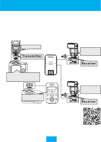
This product is a wireless transceiver, transmitting &
receiving mode will automatically switched. to express
conveniently, in this user manual, it is called transmitter
(master control unit) when being installed on the hot
shoe of the camera, while it is called receiver (slave unit)
when a flash is installed or connected.
YN622C-TX
LCD Display
Recommended optional YN622C-TX E-TTL
wireless flash controller as a transmitter,
about the introduction of this product,
please visit the following website :
http://www.hkyongnuo.com/e-detaily.php?ID=348
Off-Camera
Flash
622
560- RX
OFF
YN622C II
Off-Camera
Flash
Flash Control Menu
(Camera Menu)
On-Top Flash

Thank you for purchase the products of Yongnuo firstly.
The new upgrade version YN622C II can set to "622" or
"560-RX" communication mode through the power
switch, supports receiving the trigger signal of the
YN560-TX/RF605(603 mode)/RF603(II) series products,
with multi aspects improved, equipped with quick lock
design and supports USB firmware upgrade.
YN622C II E-TTL wireless flash trigger is a high
performance master and slave equipment of multiple
flashes photography, through digital FSK 2.4GHz radio
wireless transmission, and different photographic effects
can be realized through setting your flash at 360 degrees.
It design of transceiver, the distance of remote control
reaches 100M, supporting 7 wireless channels and A/B/C
three groups.
Remotely change the modes and parameters of the flash
quickly when using the Canon EOS series DSLR cameras
which supports external flash function , such as TTL ratio
or manually set each group of flash output. Support
high-speed sync, the max sync speed is 1/8000s*,
Support E-TTL, Manual and Multi flash modes. Support
E-TTL flash installing on the top of transmitter.
※Compatible cameras/flashes is needed when using TTL
function
※ The highest sync speed of some camera types is
1/4000s, some of flash or camera models may reach to
1/250s only or less if it doesn't support high sync
speed.
Function Introduction
2

Quick lock design
Supports USB firmware upgrade
S u p p o r t s " 6 2 2 " c o m m u n i c a t i o n m o d e ," 5 6 0 - R X "
communication mode
Compatible flash mode: E-TTL (II)/ Manual/ Multi
Compatible Shutter sync: 1st curtain, 2nd curtain, high
speed sync (HSS/FP), Max 1/8000s sync speed
Control remote flash using camera's flash control menu
screen(Remote Control Mode)
Support E-TTL / Manual/ Multi flash mode mix using(Mix
Control Mode)
Flash on hot-shoe of transmitter supports ETTL
Support Flash Exposure Compensation (FEC)
Support Flash Exposure Bracketing (FEB)
Support Flash Exposure Lock (FEL)
Support modeling Flash
Support E-TTL group ratio (ALL/ A:B/ A:B C)
Support Manual/Multi group (ALL/ A:B/ A:B:C)
Support flash zooming (auto, manual)
Support AF assist beam emitter(AF Lamp)
Support PC port triggering strobe flashes and support
1st, 2nd curtain/HSS (Super Sync)
Support LCD Live view triggering
Support high-speed continuous shooting trigger
Settings saved automatically
Compatible with ALL YongNuo/ Canon EXII series flashes
Support single-contact of camera & flash triggering
(max sync speed is 1/250s)
Supported Functions List
3

List of Type A cameras: Canon EOS 1DX/EOS 5D Mark II/
5DMark III/1Ds Mark III/1D Mark IV/1D Mark III/
6D/7D/7DII/60D/70D/50D/40D/450D/
500D Series/600D Series/700D Series/1000D Series
List of Type B cameras: Canon EOS 5D/10D/20D/30D/
300D/350D/400D/1D/1D Mark II
Compatible ETTL flash list: (support wireless remote
control through camera menu)
Canon 600EX(RT)/580EXII/430EXII/320EX/270EX(II)
YongNuo YN600EX-RT /YN568EX(II)/YN565(II)/
YN468(II)/YN467(II)/YN465
Compatibility List
4
Functions supported by the product depend on the
camera and flash used. According to different types of
cameras, in this user manual, the EOS DSLR camera with
external flash(speedlite) control menu is called type A
camera; while EOS DSLR camera without external flash
control menu is called type B camera; other camera
brands with standard hot-shoe is called type C camera.
430EX/550EX/580EX or other parts of the flash is not
supported remote control via the camera menu, need to
manually set the flash modes(parameters).
※ When using general type manual flash or strobe
flash connect to PC port, flash output needs to be
set manually.
※ In this user manual, assumes that you are using the
type A camera and compatible ETTL flash, as for
type B/ C camera, please refer to page 22.
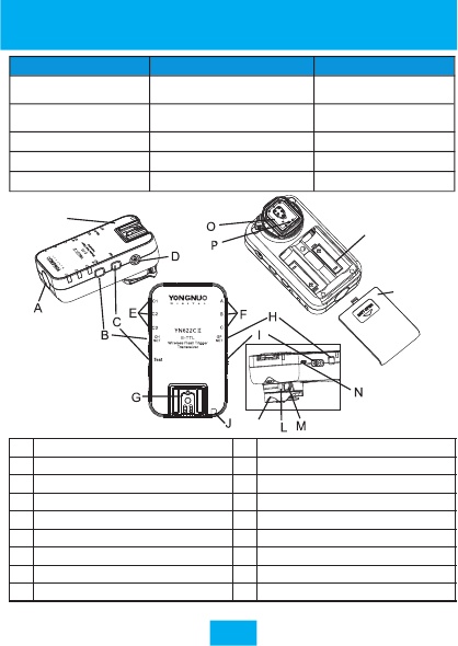
Name of Parts
※The protective film can be torn out.
5
Indicator Blinking Keep Lighting
Channel Indicator Communicating
(Remote control mode)Mix Control Mode
Group Indicator Firing group or
receiving group Testing
Communicating
State Indicator(green)TX Communicating(622) Testing Communicating
State Indicator(red)
State Indicator(orange)
RX Communicating(622)
RX Communicating(560-RX)
Standby State
Standby State
A
I
PC port(p.23)
B
J
AF assist beam emitter(p.24)
C
K
D
L
Mounting foot(p.6/7)
USB upgrade terminal(p.26)
E
M
locking pin(p.6)
F
N
G
O
Battery compartment cover(p.6)
H
P
Battery compartment(p.6)
Q
R
Mounting foot lock lever(p.6/7)
Lock-release button
Dust and water resistant adapter
622
560 -R X
OFF
K
Q
R
Channel indicator (p.8)
Group indicator (p.8/9)
Hot shoe(p.6/7)
Group setting button(p.8/9)
Channel setting button (p.8/9)
Test button(p.9/10)
Power switch(p.8)
State indicator(p.5)
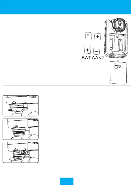
1. Installing the Batteries
※ Remove the batteries when the product is
not used for long time.
※ Please replace the both two batteries at
the same time.
Open the cover and install two AA
batteries (excluded)according to the
+ a n d - m ark s , rec harge abl e
batteries of 1.2V can be used. When
in low battery, the status indicator
light will blink(red) separately, at
the moment need to replace battery.
Preparation Before Use
6
※ It is supported that install a flash on the hot shoe of
the transmitter(on-top flash).
1).Attach the transmitter.
Slip the transmitter's mounting foot
all the way into the camera's hot shoe.
2). Secure the transmitter.
On the mounting foot, slide the lock
lever to the right. When the lock lever
clicks in place, it will be locked.
3).Detach the transmitter.
While pressing the lock-release
button, slide the lock lever to the left
and detach the transmitter.
2.Attaching and Detaching the Transmitter
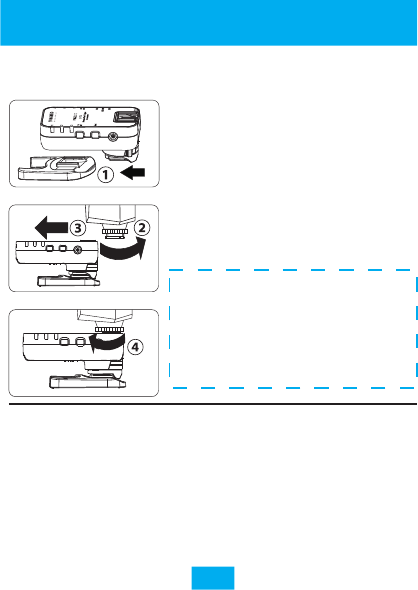
3.Install Flash on the Hot Shoe of the
Transceiver (as Receiver)
Preparation Before Use
7
!
connected reliably before use, turn all equipments
on, setting the transceivers in the same channel,
set the group of receivers , test button can be used
to awaken and test whether the flash works before
shooting(refer to Page 10), trigger the flash until
flash recyling completely.
Check that all equipments are installed and
Caution! The hot shot of the
transceivers can only install
flash being applicable to DSLR
cameras, can not install high-
v o l t a g e f l a s h , o r t h e
transceiver may be damaged.
1. Install the transceiver into the flash
bracket or other fixing devices (Not
included in the product box).
2.Make sure the mounting foot lock
of the flash is released
3.Slide the flash’s mounting foot
into the transceiver ’s hot shoe
fully.
4.Lock the flash in place.
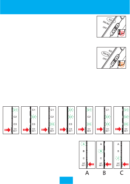
2. Channel Setting (Shortly Press [CH SET] Button)
Shortly press [CH SET] button and the channel indicator will keep
lighting for several seconds to indicate the current channel,
shortly press [CH SET] button again to change channel, and there
are totally 7 channels. Set all the transceivers at same channel.
Setting
Ch7
Ch6
Ch5
Ch4
Ch3
Ch2
Ch1
Short press [GP SET] button to check
the current receiving group, then
shortly press [GP SET] button again to
change among A/B/C three groups.
8
3. Receiving Group Setting (Press [GP SET] Button)
1.Power switch
The YN622C II adopts 3 sections of power
switch design. When it set in the “622”
communication mode, the red indicator light
will bright, when set in the “560-RX’
communication mode, the orange indicator
light will bright, “OFF”for power off.
When it used with the YN622C series
products, please set the power switch on
“622”position,transmitting/receiving mode
will automatically switched. For the relevant
usage of 560-RX please refer to page 25.
Red Indicator
(622mode)
Orange Indicator
(560-RX mode)
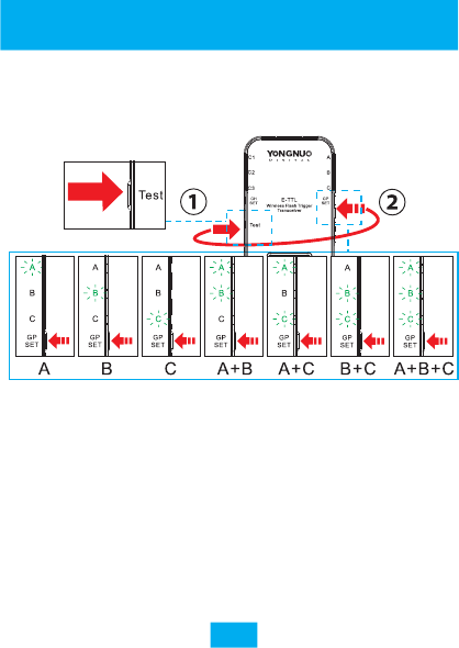
4.Flash Test Group Setting (Test + GP SET Button)
Set flash testing group
Type C camera uses the set firing group.
Setting
9
1. H o l d d o w n [ Te s t ] b u t t o n t h e n t h e g r o u p
indicators will keep lighting, the flash on the receiver
group having been selected will be woken up(p.10).
2. Hold down [Test] button and repeat to shortly
press [GP SET] button, selected groups of receivers to
testing flash, and there are totally 7 combinations.
3. When loosening [Test] button, the flash of the group
having been selected will fire a test flash(p.10).
※ Testing group is different from iring
g r o u p se tt i n g of t yp e A ca me r a r ef e r to
page 18 while page 22 for type B.
firing group, f
YN62 2C Ⅱ
622
560 -R X
OFF
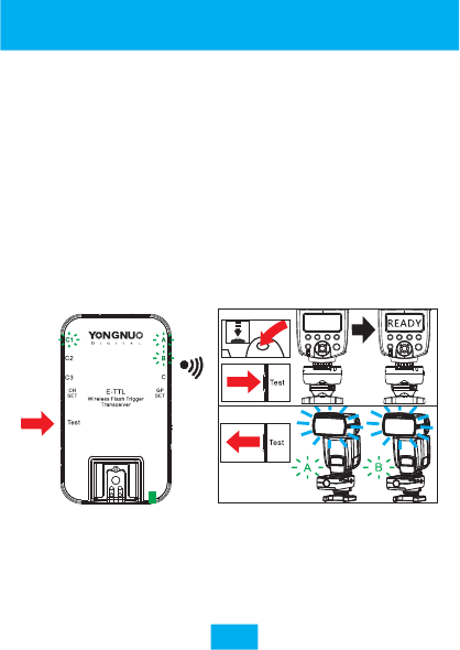
When half-pressing the shutter button of the
camera, the hot-shoe flash on the receiver will be
awakened. (for A/B type camera only)
Under any connection type, [Test] button can be
pressed to awaken and test the flash on the transceiver
and other transceivers at the same channel.
Test flash with the mode set by the flash, and under
the mode of E-TTL it may fire in a lower output.
Refer to the following figure, the transmitter sets A
+B two groups of flash test, hold down the[Test] button,
the flash on A and B of the receiver will be awakened,
and when loosening [Test] button will fire a test flash.
Flash Awaking and Testing Flash
※ If the flash can not be awakened, manually
awaken the flash before shooting.
※ Using PC port to connect with flash without the
awakening function.
※ All the indicators going out when flash fires.
10
YN622C II
622
560- RX
OFF
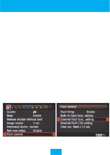
1. Press down [MENU] button on the camera, select flash
control-external flash function setting. When the off-camera
setting which is consistent with the camera’s menu, the AF
assist beam emitter of the receiver will blink twice to show
that the change is successfully.(p. 24)
2. Enabled the wireless flash function via the camera’s menu to
realize firing group control.(p.17)
3. Focus and shoot picture, the flash is fired according to the
parameters set of all groups. Support the function of AF assist
beam emitter of the transmitter. (p.24)
Remote Control Mode
11
※Suggest disabled wireless flash function when using 2st
curtain sync only.
Remotely setting all the flashes through the external flash
function setting (camera menu) of the camera, just likes the flash
being directly installed on the camera. The settings of camera
menu is prior, settings will upgraded to the receiver after
pressing down camera confirmation button or half pressing
shutter button without needing to operate the flash control
panel, the flash’s screen will display the current setting. The
setting varies depending on the cameras/flashes. This control
mode is the default control mode, transmitter ’s channel
indicator will goes out in standby state, the camera needs to be
set at P/AV/TV/M exposure mode, and it for type A cameras only.
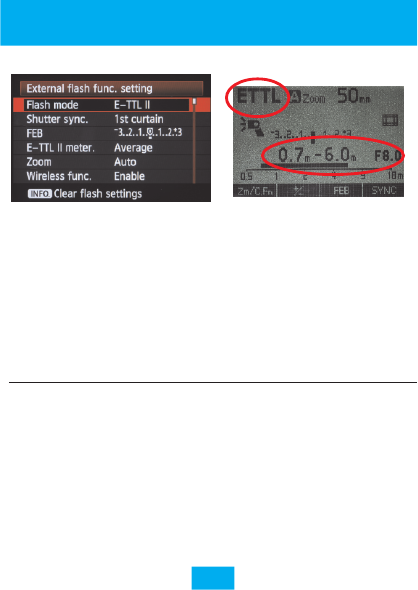
1. Select flash mode as E-TTL II mode.
2. Half press camera's shutter button to focus, and on
the flash screen the aperture and effective range etc.
parameters will be displayed.
3. Ensure that the subject is in the effective flash range,
full press camera’s shutter button to shoot, the
flash will be fire according to the setting.
※Exposure lever increments may set to 1/3-stop via
the camera.
E-TTL II metering
FEL: Flash Exposure Lock
Modeling flash
Automatic Flash (E-TTL II)
Fully-automatic Flash Shooting
12
vThe following E-TTL functions are advanced
application, please refer to the usermanual by the
manufacturer of the camera and flash.
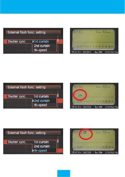
2. 2nd curtain sync
The flash fires right before the shutter closes, lower shutter
speed needs to be used, support bulb 2nd curtain sync flash.
※Only when wireless flash function via the flash control menu
is disable , the 2nd curtain sync can be use.
1. 1st Curtain sync
The normal flash sync.
Shutter Sync
13
3. Hi-speed Sync(HSS/FP FLASH)
The flash can sync with all shutter speeds when .
The max speed is 1/8000s or 1/4000s(depends on the camera).
using HSS
※ In case of using hot-shoe flash which does not support hi-
speed sync, the max sync speed is 1/250s or less.