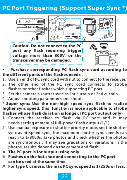
YONGNUO PHOTOGRAPHIC EQUIPMENT YN622CII Wireless Flash Trigger Transceiver User Manual PMZ SMS 026 622II C V1 0
SHENZHEN YONGNUO PHOTOGRAPHIC EQUIPMENT CO., LTD Wireless Flash Trigger Transceiver PMZ SMS 026 622II C V1 0
Contents
- 1. User Manual-1
- 2. User Manual-2
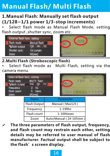
User Manual-2
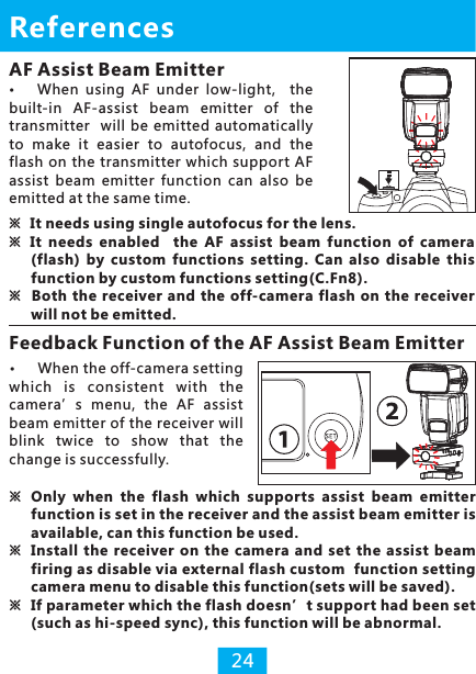
![Zoom supports automatic/manual setting.1. With automatic setting, focal length of the flash may change with lens focal length. 2. With manual setting, focal length of the flash supports manual setting within 24-105MM.1. Automatic Setting 2. Manual SettingZoom (Flash Coverage)3. Zoom Lock15Hold down the [CH SET] button of the receiver for seconds until channel indicator keeps lighting (same to set the mix control mode for the transmitter, p.21), enable the zoom lock function for the receiver, then the flash on the receiver will not be controlled by the camera menu, adjust flash zoom settings with flash control panel (automatic or manual), that means each flash can be set with a different focal. Hold down the [CH SET] for seconds again to cancel.](https://usermanual.wiki/YONGNUO-PHOTOGRAPHIC-EQUIPMENT/YN622CII.User-Manual-2/User-Guide-2751044-Page-2.png)
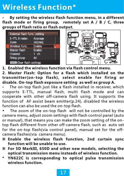
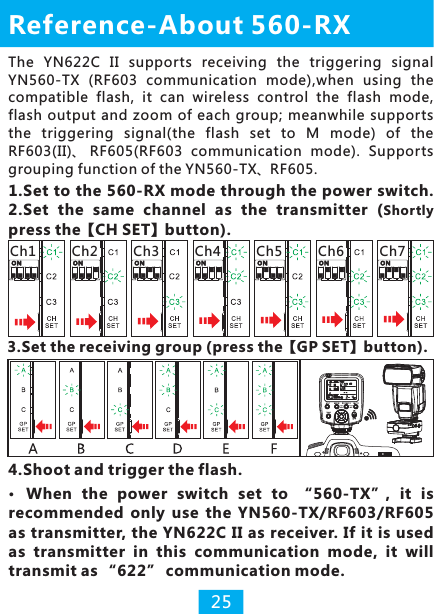
![3.Channel Setting via Wireless Function ※When disabled the wireless function via the camera menu, in transmitting communications, group indicator will go out, firing group consists of all (A+B+C), all groups of flashes using the same setting.4. Firing Group Setting via Wireless FunctionSets firing group of the transmitter via wireless function setting, in transmitting communications, state indicator and group indicator both blinking green, the following table shows that each group indicator stands for different firing group available.Wireless FunctionSet channel (CH1-CH4 only) of the transmitter via wireless function setting, the changed shall cover the original setting. CH1-CH7 may also be set by directly pressing [CH SET] at the transmitter(p.8).18 Group Indicator Firing GroupIndicator A blinks ALL(A+B+C)Indicator B blinks (A:B)Indicator C blinks A:BC or A:B:CIndicator goes out ALL(A+B+C)YN622C II622560 -RXOFF](https://usermanual.wiki/YONGNUO-PHOTOGRAPHIC-EQUIPMENT/YN622CII.User-Manual-2/User-Guide-2751044-Page-5.png)
![1. Hold down the [CH SET] button for several seconds of the transmitter until the channel indicator blinks for 3 times and then keep lighting, enable the mix control mode.2. Flash mode of the transmitter will be fixed at E-TTL and the zoom setting is disabled.3. Set the parameters of each flashes via it own control panel.Mix Control Mode21Set the flash on each receiver in different flash modes as Manual/E-TTL/Multi for mix control, the settings of the flash is prior , channel indicator of the transmitter will keep lighting when enabled this control mode. Supports type A/B cameras using. In the mix control mode, set items via the flash it supports: Flash mode (output), FEB, FEC, Zoom etc.Set the shutter sync via camera menu and the flash set is invalid (Type B camera defaults to hi-speed sync). ※ Disable the mix control mode by hold down [CH SET] button again then it will return to remote control mode (the channel indicator goes out in standby state).(p.11)](https://usermanual.wiki/YONGNUO-PHOTOGRAPHIC-EQUIPMENT/YN622CII.User-Manual-2/User-Guide-2751044-Page-8.png)
![22Type B Cameras:There is no flash control menu of such type of cameras that some of function will be restricted. Enable the mix control mode of the transmitter before using(P.21).1.Setting of transmitting groups (set in the transmitter when it in transmitting status):Half press the camera’s shutter button then status indicator blinks green. Press [GP SET] to set transmitting firing groups.Flash Triggering of B/C Type CameraType C Cameras: Manually set the Flash Output1. Transmitting group set (via the transmitter):Set according to testing group of transmitter (p.9).2. Flash mode set (via the flash control panel):Set the manual(M) flash output via the control panel of the flash, and trigger with transmitter's main flash contact(single contact). Do not support hi-speed sync or other TTL functions.(Max speed sync is 1/250s or less)2.Setting of flash mode (via the flash control panel):1). Automatic (ETTL) mode supports automatic flash, supports the settings of FEC and FEB, it defaults to hi-speed sync.2). Manual (M) mode, manually set the flash output. It defaults to hi-speed sync.3). Multi mode, set according to the flash. Group Indicator Firing GroupIndicator A blinks ALL(A+B+C)Indicator B blinks (A:B)Indicator C blinks ALL(A+B+C)](https://usermanual.wiki/YONGNUO-PHOTOGRAPHIC-EQUIPMENT/YN622CII.User-Manual-2/User-Guide-2751044-Page-9.png)
![References26Factory ResetYN622C II622560 -RXOFFFirmware Update1.Log in the YONGNUO official website:http://www.hkyongnuo.com/e-detaily.php?ID=364 to download the firmware update software and the latest firmware. 2.Power off, use Micro-USB(do not include) cable connect to PC. 3.Press the <CH SET> button and set the power on, all the indicator bright(green).4.Complete the firmware upgrade operation according to the prompt of software.YN622C Ⅱ622560 -RXOFFAbout Automatic Saving FunctionThe transceiver will automatically save the sets such as channel, receiving group, AF assist beam. In the TTL set, some parameters will not be saved, such as the set of fire ratio etc.1) Hold down the buttons [CH SET] plus [GP SET] at the same time.2) The state indicators will blink for 3 times in red-green alternately then turn to keep lighting (red).3) Release all the buttons then reset the factory set.YN622 C II622560-RXOFF](https://usermanual.wiki/YONGNUO-PHOTOGRAPHIC-EQUIPMENT/YN622CII.User-Manual-2/User-Guide-2751044-Page-13.png)
![Troubleshooting1. Fail to power on or automatic shutdown: The battery is loaded inversely or exhausted; indicator light will blink(red) separately when the batter y is going to be exhausted, and it will power off automatically in case of being over discharged.▲Install the battery according to the correct direction, ensure the battery is full and restart the power (refer to page 8).2.The flash doesn't fire: Ensure the power of all are full, the connection among the transceiver, camera and the flash is reliable; whether the indicator is set in the same channels and controllable groups. Flashes recycle process, entering in the state of overheating protection, the flash enters into sleep status etc. may makes the flash doesn't fire. Ensure the flash is in ready state, use the [Test] button test the flash before using.Check the power switch of the receiver to see if it set to correct communication mode. Such as the receiver set to “560-RX” mode, it will not receive the signal of “622". 3. Fail to enable the 2nd curtain sync:That’s because the restriction of camera menu.▲It shall set the wireless function disabled if needs using the 2nd curtain sync.4. Can't access into the external flash function menu or the menu is displayed abnormally:The transmitter is not installed right , the contacts of the hot shoe is stained or the power of the batter y is exhausted.▲Reinstall the transmitter and clean the contacts ,replace the batteries.5.The channel indicator bright all along, unable to change the flash mode and zoom of camera menu.It is because enable the “mix control mode”.▲Please long press the “CH SET” button to exit the mix control mode or restore to factory settings. the status 27](https://usermanual.wiki/YONGNUO-PHOTOGRAPHIC-EQUIPMENT/YN622CII.User-Manual-2/User-Guide-2751044-Page-14.png)