Yaesu Musen 10353030 VHF Transceiver User Manual p65
Yaesu Musen Co., Ltd. VHF Transceiver p65
UserManual.wiki
>
Yaesu Musen
>
10353030 User Manual
USERS MANUAL
Navigation menu
Upload a User Manual
Namespaces
Wiki Guide
HTML
PDF
Info
Views
User Manual
Discussion / Help
Navigation
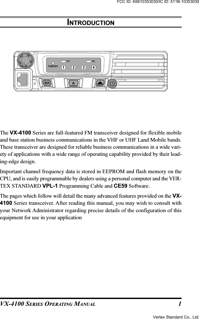
![VX-4100 SERIES OPERATING MANUAL2P2P1TX/BUSYA1234CONTROLS & CONNECTORSFront PanelImportant! - All buttons located on the Front Panel are Programmable Function (PF)Buttons, configured according to your network requirements and programmed byyour VERTEX STANDARD dealer. The instructions below discribe a typically-con-figured radio.VOL KnobTurn this control clockwise to increase the volume.Microphone JackConnect the microphone plug to this jack.Emergency MicrophoneThe emergency microphone is located behind this small slit. When the emer-gency feature is activated, this microphone is enabled.[MON], [A], [] Buttons (Programmable Function Buttons)These buttons can be set up for special applications, such as High/Low powerselection, Monitor, Talk-Around, etc., as determined by your network require-ments and programmed by your VERTEX STANDARD dealer. (POWER) ButtonPress and hold in this button for 2 seconds to toggle the transceiver’s power “on”and “off.”FCC ID: K6610353030/IC ID: 511B-10353030Vertex Standard Co., Ltd.](https://usermanual.wiki/Yaesu-Musen/10353030/User-Guide-489613-Page-4.png)
![VX-4100 SERIES OPERATING MANUAL6Automatic Time-Out TimerIf the selected channel has been programmed for automatic time-out, you must limitthe length of each transmission. While transmitting, a beep will sound 10 secondsbefore time-out. Another beep will sound just before the deadline; the red “TX”indicator will disappear and transmission will cease soon thereafter. To resume trans-mitting, you must release the PTT switch and wait for the “penalty timer” to expire(if you press the PTT switch before this timer expires, the timer restarts, and you willhave to wait another “penalty” period)Key LockIn order to prevent accidental frequency change or inadvertent transmission, variousaspects of the VX-4100’s keys, and the PTT switch, may be locked out. The preciselockout configuration must be programmed by your VERTEX STANDARD dealerTo activate the Locking feature, press and hold in the [A] key while turning the radioon. To disable the Locking feature, repeat this power-on procedure.BASIC OPERATION OF THE TRANSCEIVERFCC ID: K6610353030/IC ID: 511B-10353030Vertex Standard Co., Ltd.](https://usermanual.wiki/Yaesu-Musen/10353030/User-Guide-489613-Page-8.png)

![VX-4100 SERIES OPERATING MANUAL12DIRECT CH#1 TO DIRECT CH#4Press the assigned programmable key to recall the Dealer pre-programmed channeldirectly.REC/PLAY (VOICE STORAGE: OPTION)This function, which requires the optional Voice Storage Unit, allows you to recordand play back incoming receiver audio.Recording:Press the assigned Rec/Play programmable key for more than 1.5 seconds to togglethe recording feature “on” and “off.” If the incoming signal is being heard throughthe speaker when the recording feature is set to “on,” the received audio will berecorded. The last 2 minutes of incoming audio will be stored on a first-in, first-outbasis.Playback:Press the assigned Rec/Play key momentarily to start playback. During playback,pressing then [] key lets you jump forward 8 seconds. To stop playback before thestored message is complete, press the [A] key.AF MIN VRPress the assigned programmable key to reduce the audio output to the (lower) levelprogrammed by your Dealer.ADVANCED OPERATIONFCC ID: K6610353030/IC ID: 511B-10353030Vertex Standard Co., Ltd.](https://usermanual.wiki/Yaesu-Musen/10353030/User-Guide-489613-Page-14.png)