Yaesu Musen 10623X20 Portable Transceiver User Manual USERS MANUAL
Yaesu Musen Co., Ltd. Portable Transceiver USERS MANUAL
UserManual.wiki
>
Yaesu Musen
>
10623X20 User Manual
USERS MANUAL
Navigation menu
Upload a User Manual
Namespaces
Wiki Guide
HTML
PDF
Info
Views
User Manual
Discussion / Help
Navigation
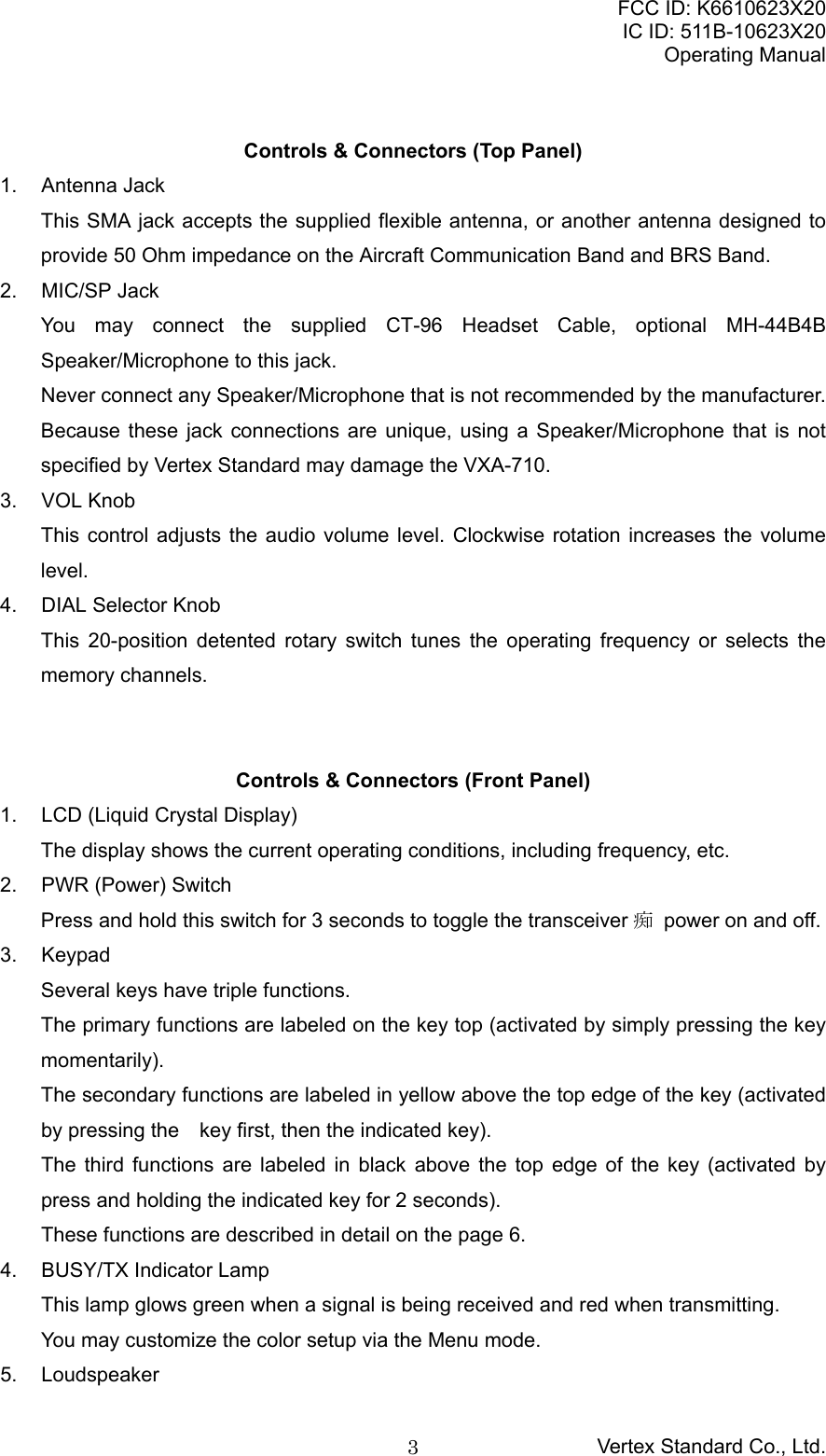
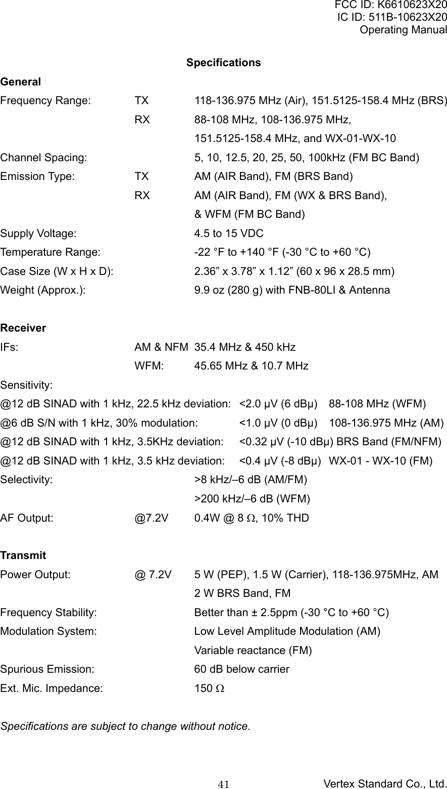
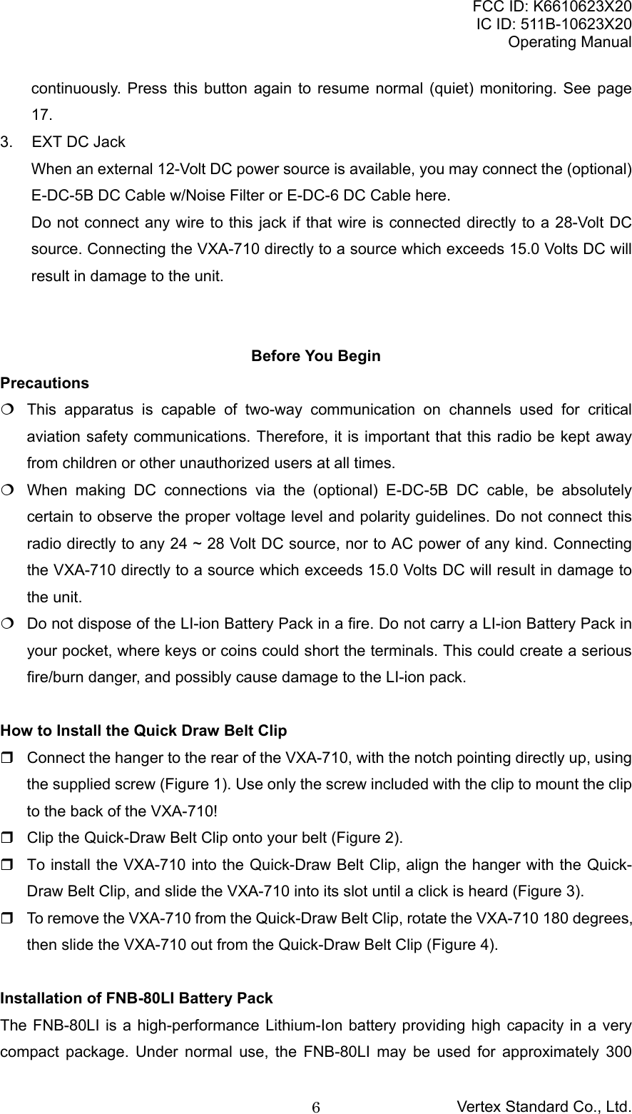
![FCC ID: K6610623X20IC ID: 511B-10623X20Operating ManualVertex Standard Co., Ltd.4The internal speaker is located in this position.6. MicrophoneSpeak across this opening in a normal voice level while pressing the PTT switch, totransmit.7. Battery Pack LatchOpen this latch for battery removal.Primary Function(Press Key)Secondary Function(Press + [F])Third Function(Press & Hold)[1(VOR)TN] Frequency entry digit“1.”Activates VORmode.Recalls Menu Item“SQL Type” (foractivating theCTCSS or DCSoperation on theBRS mode).[2(TO)CD] Frequency entry digit“2.”Selects “TO” VORmodeRecalls Menu Item“TONE Set” (forselecting theCTCSS tonefrequency on theBRS mode)[3(FROM)DT] Frequency entry digit“3.”Selects “FROM”VOR modeActivates the DTMFAutodialer function.[4(CDI)] Frequency entry digit“4.”Activates the CourseDeviation Indicatormode.None[5(APO)] Frequency entry digit“5.”None Recalls Menu Item“APO” (for settingof the AutomaticPower Off time).[6(TAG)] Frequency entry digit“6.”Selects the displaytype (Frequency orAlpha-numeric Tag)during Memoryoperation.None[7(SPL)ST] Frequency entry digit“7.”None Recalls Menu Item“Step” (for settingof the synthesizersteps).[8(BEEP)] Frequency entry digit“8.”None Recalls Menu Item“Beep” (for settingof the keypadbeeper).[9(SKIP)] Frequency entry digit“9.”None Sets the MemorySkip (Omit) featureto the currentmemory channel.[0(SQ)] Frequency entry digit“0.”None Recalls Menu Item“SQL” (for settingthe squelch](https://usermanual.wiki/Yaesu-Musen/10623X20/User-Guide-510489-Page-4.png)
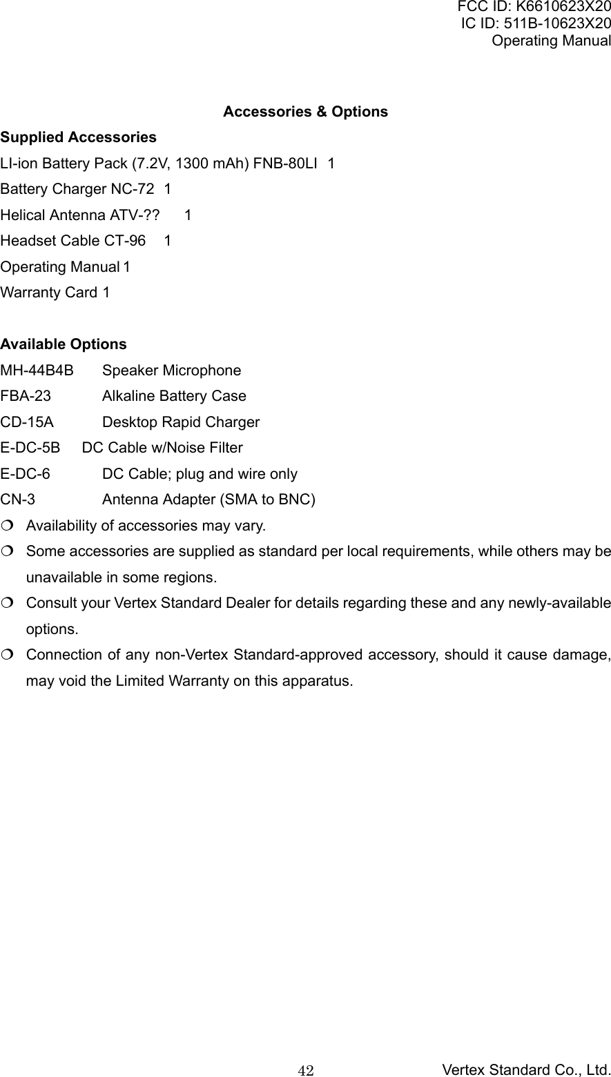
![FCC ID: K6610623X20IC ID: 511B-10623X20Operating ManualVertex Standard Co., Ltd.5threshold level.[BAND(MODE)] Select the operationband between theAIR band and FM BCband in the VFOmode.Select the operationmode between theFM and Narrow FMon the BRS mode.None[121.5(HOME)] Selects theEmergency Channel(121.5 MHz).Switches operationto the “Home”(favorite frequency)channel.None[MW(SPL.W)] None Split-Memory “Write”Command.Memory “Write”Command.[SCAN(DW)MT] Activates theScanner.Activates DualWatch.Activates the“Memory Tune”mode while in theMemory Recallmode.[SEL(SET)] Select the tuningmethods among theVFO, MR, BMR, WX,and BRS1.Enter the “Set”(Menu) mode.None[USER(KEY)]Ú2Activate theAutomatic NoiseLimiter during AMreception.Lock the Keypad. Switches thefrequency displaybetween the “LargeCharacter” and“Small Character”mode.[F] Activates the“Secondary” keymode.None NoneÚ1: VFO: Variable Frequency OscillatorMR: Memory RecallBMR: Pre-Programmed MemoriesWX: Weather Channel MemoriesBRS: Business Radio ServiceÚ2: The Primary and Third function of the [USER(KEY)] key may be customized by uservia the Menu mode. See page ??.Controls & Connectors (Side Panel)1. PTT (Push To Talk) SwitchPress this button to transmit when you are operating in the COM band or BRS band.Release this button to return to the “Receive” mode. See page 15.2. MONITOR SwitchThis button may be pressed to “Open” the squelch manually, allowing you to listen forvery weak signals. Press and hold this button for 2 seconds to “Open” the squelch](https://usermanual.wiki/Yaesu-Musen/10623X20/User-Guide-510489-Page-5.png)
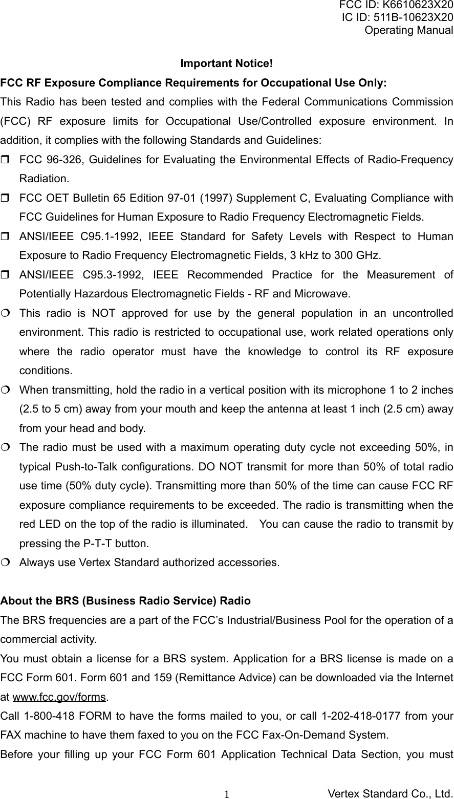
![FCC ID: K6610623X20IC ID: 511B-10623X20Operating ManualVertex Standard Co., Ltd.8Notes: The FBA-23 is designed for use only with AA-type Alkaline cells. If you do not use the VXA-710 for a long time, remove the Alkaline batteries from theFBA-23, as battery leakage could cause damage to the FBA-23 and/or the transceiver.Low Battery Indication As your battery discharges during use, the voltage will gradually become lower. Whenthe “BATTERY” icon will blink on the LCD display, the battery pack must be rechargedbefore further use. Avoid recharging Li-Ion batteries before the “Low Battery” indicator is observed, as thiscan degrade the charge capacity of your Li-Ion battery pack. Vertex Standardrecommends that you carry an extra, fully-charged pack with you so you will not losecommunications capability due to a depleted Li-Ion battery.This “deep cycling” practice will help to maintain longer overall battery life after manyrecharging cycles.AC Operation Using NC-72B/C (Receiving only)The VXA-710 may be operated from your house current by use of the supplied NC-72B/CBattery Charger. The NC-72B/C should only be used for reception, because it is not capableof supplying sufficient current to support transmission.To use the NC-72B/C, turn the transceiver off, then plug the miniature connector of theBattery Charger into the EXT DC jack on the side of the radio. Now plug the Battery Chargerinto the wall outlet. You may now turn on the transceiver.Basic OperationPreliminary Steps Install a charged battery pack onto the transceiver, as described previously. Screw the supplied antenna onto the Antenna jack. Never operate this transceiverwithout an antenna connected. If you have an optional Speaker/Microphone or headset. we recommend that it not beconnected until you are familiar with the basic operation of the VXA-710.Operation Quick Start To turn the radio on, press and hold in the PWR Switch for 3 seconds. The opening message will appear on the display, then frequency display will appear. Press the [BAND(MODE)] key to switch the operating band between the AIR band and](https://usermanual.wiki/Yaesu-Musen/10623X20/User-Guide-510489-Page-8.png)
![FCC ID: K6610623X20IC ID: 511B-10623X20Operating ManualVertex Standard Co., Ltd.9FM BC band. Directly entering frequencies from the keypad is the easiest method if you know thefrequency on which you wish to operate. Just enter the five digits of the frequency tomove to that frequency. However, there is a short-cut for frequencies ending in zero -press the [SCAN(DW)MT] key after the last non-zero digit.For example, to set 134.35 MHz:press [1] Æ [3] Æ [4] Æ [3] Æ [5].To set 118.000 MHz:press [1] Æ [1] Æ [8] Æ [SCAN(DW)MT].To set 118.275 MHz, you do not need to press the final “5” in the frequency:press [1] Æ [1] Æ [8] Æ [2] Æ [7].Note: When the entered frequency is outside of the current operating band, the entry isignored (i.e. VXA-710 does not permit entry of a FM BC band frequency while operatingin the AIR band). You may also turn the top panel’s DIAL selector knob to choose the desired operatingfrequency. The channel frequency will appear on the LCD. To change frequency in 1 MHz steps, press the [F] key momentarily, then rotate theDIAL selector knob to select the MHz digit desired. Press the [F] key once more toresume normal channel step. Rotate the VOL knob to set the volume level. If no signal is present, press and hold inthe MONITOR button for 2 seconds; background noise will now be heard, and you mayuse this noise to set the VOL knob for the desired audio level. Press the MONITORbutton momentarily to silence the noise and resume normal (quiet) monitoring. To turn the radio off, press and hold in the PWR switch for 3 seconds.Squelch Adjustment Press and hold in the [0(SQ)] key for 3 seconds. This instantly recalls Menu Item “SQL:”on the AM or FM mode or “WSQL:” on the WFM mode (for the Broadcasting Station). Press the [SEL(SET)] key to enable adjustment of this Menu Item. Rotate the DIAL selector knob to set the squelch threshold (0 - 8) so that the receiver isjust silenced. A higher number indicates that a higher signal level is required in order toopen the squelch. When you have made your setting, press the [SEL(SET)] key to save the new setting,then press the PTT key repetitively until the radio exits to normal operation.Accessing the 121.5 MHz Emergency FrequencyThe VXA-710 can quickly access the 121.500 MHz Emergency Frequency. This function](https://usermanual.wiki/Yaesu-Musen/10623X20/User-Guide-510489-Page-9.png)
![FCC ID: K6610623X20IC ID: 511B-10623X20Operating ManualVertex Standard Co., Ltd.10can be activated even when the keypad lock function is in use. To access the Emergency Frequency, press the [121.5(HOME)] key momentarily. To exit the Emergency Frequency, press the [121.5(HOME)] key momentarily.Tuning MethodsThroughout this manual, you will see references to several different frequency settingmethods by pressing the [SEL(SET)] key. Each will be particularly useful in a particularoperating situation, and they are described below: VFO (Variable Frequency Oscillator)The VFO is a “tuning dial” system which allows you to tune through the AIR band andFM BC band using the DIAL selector, the Keypad, or the scanner. To select these bands,press the [BAND(MODE)] key momentarily. MR (Memory Recall)The MR (Memory Recall) mode of the VXA-710 provides the user with the ability tostore and recall as many as 68 channels in the radio’s main memory bank. Thesememory channels may also be labeled by you with an alpha/numeric name of up to 8characters in length, to aid in quick identification of the channel. See page ?? for detailsof the Memory Channel Operation. BOOK (Pre-Programmed) MemoriesThe Book memories are pre-programmed, either at the factory or by your Dealer(depending on your country’s requirements), typically including the major AIR bandstation frequencies used in your area. The Book memories can be changed by the user.See page ?? for details. WX (Weather Channel) Memories (USA version only)Ten Weather Channels are pre-programmed at the factory. The VXA-710 willautomatically scan this special bank when it is selected by the user. See page ?? fordetails of the WX Memory Channel Operation. BRS (Business Radio Service) Memories21 BRS Channels are pre-programmed at the factory. See page ?? for details of theBRS Memory Channel Operation.Transmission To transmit, press and hold in the PTT switch. Speak into the microphone area of thefront panel grille in a normal voice level. To return to the receive mode, release the PTT switch.](https://usermanual.wiki/Yaesu-Musen/10623X20/User-Guide-510489-Page-10.png)
![FCC ID: K6610623X20IC ID: 511B-10623X20Operating ManualVertex Standard Co., Ltd.11Monitor KeyWhen listening to a very weak signal from an aircraft or ground station, you may observe thesignal disappearing periodically as the incoming signal strength becomes too weak tooverride the squelch threshold setting.To disable the squelch temporarily, press and hold the MONITOR key for 2 seconds on theleft side of the radio, just below the PTT button. The squelch will remain open and youshould have a better chance of hearing weak signals.To return to normal operation, press the MONITOR key momentarily.ANL (Automatic Noise Limiter) FeatureFor reduction of impulse noise in the AM mode, such as that produced by an engine’signition system, the ANL feature may prove helpful. To activate the ANL feature, press the [USER(KEY)] key momentarily. The “ANL” iconwill appear on the display, and you should observe a reduction in the ignition noise. To turn the ANL feature off, press the [USER(KEY)] key again; the “ANL” icon willdisappear from the display.Note: The ANL feature is only activated on the Air Band.LOCK FunctionThe lock function prevents accidental changes to the frequency setting and the keypadcontrols. To activate the lock feature, press the [F] key followed by [USER(KEY)] key. In the LOCK mode, the “LOCK” icon will appear on the display. To turn the lock feature off, press the [F] key followed by [USER(KEY)] key again. You can still access the 121.500 MHz Emergency Frequency when the LOCK function ison. Simply press the [121.5(HOME)] key momentarily (this key never locks). Pressingthis key also unlocks the radio.Beep On/OffThe VXA-710’s key/button beeper provides convenient audible feedback whenever a buttonis pressed. Each key and button has a different beep pitch, and each function has a uniquebeep combination.When you are scanning, the beeper will be heard each time the scanner halts on a busychannel. This may be distracting in some environments; if you want to turn the beeper off (orback on again): Press and hold the [8(BEEP)] key for 2 seconds. This instantly recalls Menu Item“Beeper.”](https://usermanual.wiki/Yaesu-Musen/10623X20/User-Guide-510489-Page-11.png)
![FCC ID: K6610623X20IC ID: 511B-10623X20Operating ManualVertex Standard Co., Ltd.12 Press the [SEL(SET)] key to enable adjustment of this Menu Item. Rotate the DIAL selector knob to select the desired selection.On: Sounds a keypad beeper corresponding to a musical note.DTMF: Sounds a keypad beeper corresponding to a DTMF tone.Off: Keypad beeper is “off.” When you have made your selection, press the [SEL(SET)] key to save the new setting,then press the PTT key repetitively until the radio exits to normal operation.Reception of Weather Channel Broadcasts (USA version only)The VXA-710 can receive VHF Weather Channel broadcasts, which may assist your flightplanning. The VXA-710 includes a ten-channel auto-search feature, which simplifies accessto Weather Channels when you are in an unfamiliar location. To receive Weather Channels, press the [SEL(SET)] key (repeatedly, if necessary) toselect the Weather Channel mode. In the Weather Channel mode, “WX” will appearupper left corner of the display. The VXA-710 will now scan quickly though the ten standard Weather Channels, and willstop on the first active station found. If there are two or more weather channels audible in your area, you may select thealternate channel(s) by pressing the PTT switch. Pressing the PTT switch re-initiates thescanning process. If there are no Weather Channels in your area, the scanner will not stop. Press theMONITOR button to stop the scanner. You can also select Weather Channels manually by rotating the DIAL selector knob. To exit the Weather Channel mode, press the key momentarily to return to the VFOmode.Note 1: In the event of extreme weather disturbances, such as storms and hurricanes, theNOAA (National Oceanic and Atmospheric Administration) sends a weather alertaccompanied by a 1050 Hz tone and subsequent weather report on one of the NOAAweather channels. You may setup the Alert function when receiving the Weather Alert signalvia Menu Item (6. Misc Setup, 3. WX Alert), if desired.Note 2: The Weather Channel mode memorizes the last Weather Channel you have used,and will retain this information until the radio is turned off.Receive Battery Saver SetupAn important feature of the VXA-710 is its Receive Battery Saver, which “puts the radio tosleep” for a time interval, periodically “waking it up” to check for activity. If somebody istalking on the channel, the VXA-710 will remain in the “active” mode, then resume its “sleep”](https://usermanual.wiki/Yaesu-Musen/10623X20/User-Guide-510489-Page-12.png)
![FCC ID: K6610623X20IC ID: 511B-10623X20Operating ManualVertex Standard Co., Ltd.13cycles. This feature significantly reduces quiescent battery drain, and you may change theamount of “sleep” time between activity checks using the Menu System: Press the [F] key, then press the [SEL(SET)] key to activate the Menu (“SET”) mode. Rotate the DIAL selector knob to select Menu Item “3. Receive,” then press the[SEL(SET)] key. Rotate the DIAL selector knob to select Sub Menu Item “5. RX Save,” then press thekey. Press the [SEL(SET)] key again to enable adjustment of this Menu Item. Rotate the DIAL selector knob to select the desired “duty cycle” (receive:sleep). Theselections available are 1:1, 1:2, 1:3, 1:4, 1:5, and ABS* or oFF. The default value isABS. When you have made your selection, press the [SEL(SET)] key to save the new setting,then press the PTT key repetitively until the radio exits to normal operation.*ABS: Automatic Battery Saver, based on activity on the receiver.The setting of 1:5 will promote the greatest conservation of battery capacity, but thereceiver’s response time to incoming calls will be slowed somewhat.Note: This feature does not operate during Scan, Dual Watch, or Spectrum ScopeMonitoring.Memory OperationThe VXA-710 provides 70 user-programmable Main memories, labeled “MR1” through“MR68,” “MRLch,” and “MRUch,” up to 90 pre-programmed memories, designated “Book”Memories, labeled “BMR1” through “BMR90,” and one Home channel, allowing storage andquick recall of favorite operating frequency.The Main memories and “Book” Memories can be assigned alpha-numeric names of up toeight characters.Memory System OperationThe VXA-710’s Main Memory system allows the user to store, label, and recall channelfrequencies which you may want to use frequently. You may store VFO frequencies, “Book”Memory frequencies, and/or Weather Channel frequencies (USA version only) into the MainMemory system.Memory Storage Select the desired frequency in the VFO mode, or recall the “Book” Memory channel,Weather channel, or BRS channel to be stored in the Main Memory.](https://usermanual.wiki/Yaesu-Musen/10623X20/User-Guide-510489-Page-13.png)
![FCC ID: K6610623X20IC ID: 511B-10623X20Operating ManualVertex Standard Co., Ltd.14 Press and hold in the [MW(SPL.W)] key for 2 seconds. The display will indicate “MW”and a channel number will blink on the LCD. Within five seconds of pressing the [MW(SPL.W)] key, rotate the DIAL selector knob toselect the desired memory channel number for storage. In order to prevent writing overmemory channels, an “Open Door” icon will appear at the right of the channel number toindicate if the memory channel is vacant. Now press and hold in the [MW(SPL.W)] key for 2 seconds; you will now see theblinking “A” character on the LCD. To attach an alpha/numeric name (label) to thememory, proceed to the next step; otherwise press and hold in the [MW(SPL.W)] key for2 seconds to save the entry and exit. To label a memory with an alpha/numeric name, the next step is to use the DIAL selectorknob to select any of the 125 available characters (including letters, numbers, andspecial symbols). Press the [USER(KEY)] key repeatedly to recall the desired letter,number, and symbol in the first character slot (a Æ . Æ 0 Æ A Æ a ...). When the desiredfirst character appears, press the [SEL(SET)] key momentarily to select it and move onto the next character. Select succeeding characters in the same manner, pressing the [SEL(SET)] keymomentarily after each selection. After entering the entire name (eight characters maximum), press the [MW(SPL.W)] keyfor 2 seconds to save all data for the channel and exit.Recalling the Memories Press the [SEL(SET)] key, repeatedly if necessary, until “MR” (Memory Recall) appearson the display. In the MR mode, you will see the previously-selected channel numberappearing at the bottom of the “MR” icon on the LCD. Rotate the DIAL selector knob to select the desired memory channel. You may change the readout structure of the Memory display between “FrequencyIndication” and “Frequency Indication plus Alpha-numeric Label” by pressing the [F] keyfollowed by [6(TAG)] key. To exit the Memory mode, press the [SEL(SET)] key three times to return to the VFOmode.Note 1: In either the Memory mode or the “Book” Memory mode, an easy way to recallmemories is to key in the memory channel number (except memory channel “Lch” and“Uch.” For example, to recall memory channel #06, press the [0] key followed by [6] key. Torecall memory channel #60, press the [6] key followed by [0] key.Note 2: In either the Memory mode or the “Book” Memory mode, you can change memorychannels in 10-channel steps: press the [F] key momentarily, then rotate the DIAL selector](https://usermanual.wiki/Yaesu-Musen/10623X20/User-Guide-510489-Page-14.png)
![FCC ID: K6610623X20IC ID: 511B-10623X20Operating ManualVertex Standard Co., Ltd.15knob. The “F” icon will show at the left bottom of the display when the 10-channel-steptuning mode is active. Press the [F] key once more to resume normal channel selection inone-channel steps.Memory Offset TuningOnce you have recalled a particular memory channel, you may easily tune off that channel,as though you were in the “VFO” mode. With the VXA-710 in the Memory Recall mode, select the desired memory channel. Now press and hold in the [SCAN(DW)MT] key for 2 seconds. The “MR” indicator will bereplaced by one which says “MT” (Memory Tuning). Rotate the DIAL selector knob, as desired, to tune to a new frequency. The synthesizersteps selected for VFO operation on the current band will be the steps used duringMemory Tuning. If you wish to return to the original memory frequency, press and hold in the[SCAN(DW)MT] key for 2 seconds. The “MT” indicator will be replaced by “MR.” If you wish to store a new frequency set during Memory Tuning, just press and hold inthe [MW(SPL.W)] key for 2 seconds, per normal memory storage procedure.Note: The Memory Tune feature dose not activated on the memory channel which is storedthe WX or BRS channel frequency.Deleting Memories With the VXA-710 in the Memory mode, rotate the DIAL selector knob to select thememory channel you wish to delete. Press the [F] key, then press and hold the [MW(SPL.W)] key for 2 seconds. Thepreviously-selected memory will be deleted.Note: Once deleted, channel data cannot be recovered!Home Channel MemoryA special “HOME” channel is available, to allow quick recall of a favorite operating frequency.Memory storage is simple to accomplish: Select the desired frequency in the VFO mode, or recall the “Book” Memory channel,Weather channel, or BRS channel to be stored in the “HOME” channel. Press and hold in the [MW(SPL.W)] key for 2 seconds. The display will indicate “MW”and a channel number will blink on the LCD. Within five seconds of pressing the [MW(SPL.W)] key, press and hold in the[121.5(HOME)] key for 2 seconds. The frequency and other data (if any) will now bestored in the special “HOME” channel register.](https://usermanual.wiki/Yaesu-Musen/10623X20/User-Guide-510489-Page-15.png)
![FCC ID: K6610623X20IC ID: 511B-10623X20Operating ManualVertex Standard Co., Ltd.16 To recall the “HOME” channel, press the [F] key followed by [121.5(HOME)] key.You may also attach an alpha/numeric name (label) to the “HOME” channel. Recall the “HOME” channel, by pressing the [F] key followed by [121.5(HOME)] key. Now press and hold in the [MW(SPL.W)] key for 2 seconds; you will now see theblinking “A” character on the LCD. Use the DIAL selector knob to select any of the 125available characters (including letters, numbers, and special symbols). Press the[USER(KEY)] key repeatedly to recall the desired letter, number, and symbol in the firstcharacter slot (a Æ . Æ 0 Æ A Æ a ...). When the desired first character appears, pressthe [SEL(SET)] key momentarily to select it and move on to the next character. Select succeeding characters in the same manner, pressing the [USER(KEY)] keymomentarily after each selection. After entering the entire name (eight characters maximum), press the [MW(SPL.W)] keyfor 2 seconds to save all data for the channel and exit. Press the [F] key followed by [6(TAG)] key to change the readout structure of theMemory display between “Frequency Indication” and “Frequency Indication plus Alpha-numeric Label.”Scanning OperationBasic ScanThe VXA-710 allows you to scan automatically in the VFO*1, Main Memory, “Book” Memory,Weather Channel*2, or BRS channel modes. It pauses on signals encountered, so you cantalk to the station(s) on that frequency, if you like.*1: In the VFO mode, the automatic scanner is only available in the current operating band(AIR band or FM BC band). Furthermore, on the AIR band, the automatic scanner is onlyavailable in the COM band (118.000 - 136.975 MHz); when the scanner reaches theuppermost frequency in the COM band, it will revert to the bottom end of the COM band andrepeat the scanning process until you cancel the scanning process.*2: USA version only.If you wish to scan in the NAV band (108.000 - 117.975 MHz), you can do so manually, asdescribed below.Scanning operation is basically the same in each of the above modes. Press the [SCAN(DW)MT] key momentarily to start the automatic scanner upward(toward a higher frequency or a higher channel number). When the scanner encounters a signal, scanning pauses and the radio remains on that](https://usermanual.wiki/Yaesu-Musen/10623X20/User-Guide-510489-Page-16.png)
![FCC ID: K6610623X20IC ID: 511B-10623X20Operating ManualVertex Standard Co., Ltd.17channel until one second after the signal disappears, after which scanning will resume. While the scanner remains paused on a frequency, the decimal point of the frequencydisplay blinks. The display will be illuminated unless the Scan Lamp Feature is turnedoff. To change the scan direction, turn the DIAL selector knob one click in the oppositedirection. To stop the automatic scanner, press the PTT switch or the [SCAN(DW)MT] keymomentarily.The VXA-710’s automatic scanner is not operational in the NAV band (108.000 - 117.975MHz), because the NAV stations (ILS, etc.) transmit constantly (thereby causing the scannerto stop repeatedly). However, you can scan manually in the NAV band, per the followingprocedure: Press and hold the [SCAN(DW)MT] key to start the manual scanner. Scanning willcontinue as long as the key is depressed. Release the [SCAN(DW)MT] key to stop the manual scanner immediately.Note: When scanning upward in frequency, when the frequency reaches the COM Band(118.000 - 136.975 MHz) via manual scanning, the VXA-710 will switch to the automaticscanner mode.Channel-Skip ScanningContinuous-carrier stations like ATIS (Automatic Terminal Information Service) or WeatherBroadcast stations inhibit scanner operation. Since these stations are always active, thescanner will be halted repeatedly on their channels. Such channels can be set to be“skipped” during Memory scanning (MR, Book, WX, or BRS modes), if you like, so as not tointerfere with automatic channel scanning: Recall the Memory Channel to be skipped during scanning. Press and hold the [9(SKIP)] key for 2 seconds. The “ icon will appear at the left of thefrequency display, indicating that the channel is to be ignored during scanning. Later, to re-enable the memory channel for scanning, repeat the first two steps. The “icon will disappear by the channel you have just re-enabled.Note: A memory set to be “skipped” is still accessible for manual memory selection usingthe DIAL selector knob.Programmable (Band Limit) Memory Scan (PMS)This feature allows you to set sub-band limits for either scanning or manual VFO operation.For example, you might with to set up a limit of COM band (118.000 MHz to 136.975 MHz.](https://usermanual.wiki/Yaesu-Musen/10623X20/User-Guide-510489-Page-17.png)
![FCC ID: K6610623X20IC ID: 511B-10623X20Operating ManualVertex Standard Co., Ltd.18Here’s how to do this: Set the radio to the VFO mode by pressing the [SEL(SET)] key and set the radio to theAIR band by pressing the [BAND(MODE)] key, if necessary. Using the techniques learned earlier, store 118.000 MHz into Memory Channel “Lch”(the “Lch” designates the Lower sub-band limit). Likewise, store 136.975 MHz into Memory Channel “Uch” (the “Uch” designates theUpper sub-band limit). Switch to the Memory mode by pressing the [SEL(SET)] key once, then rotate the DIALto select Memory Channel “Lch.” Press and hold in the [SCAN(DW)MT] key for 2 seconds to start PMS operation; the“MR” label will be replaced by “PMS” in the upper left-hand corner of the display. Tuning and scanning (pressing the [SCAN(DW)MT] key) will now be limited within thejust-programmed range.Note: The PMS feature does not activated on the WX and BRS frequencies.Dual Watch OperationThe Dual Watch feature automatically checks for activity on a “Priority” channel* while youare operating on another channel. During Dual Watch operation, the current channel and thePriority channel will each be polled for a 500 ms interval, as the VXA-710 looks for activityon each channel. To start Dual Watch, press the [F] key followed by [SCAN(DW)MT] key. The “DW” icon will appear on the display. While receiving on the “current” channel (not the Priority channel), you may push thePTT switch at any time to transmit on that channel. When a signal is received on the Priority channel, operation immediately shifts to thePriority channel; the “DW” icon will blink, and the display will become illuminated. While receiving on the priority channel, if you momentarily press the PTT switch, DualWatch will be disabled. You may then transmit on the Priority Channel. To stop Dual Watch, press the [F] key followed by [SCAN(DW)MT] key. If you wish, you may use both the Dual Watch and Scan features simultaneously. To dothis, start the Dual Watch first, then start the Scanner.* The “Priority” channel is defined as the last-used Memory Channel (when using the VFO,“Book” memory, and BRS channel modes) or Memory Channel “1” (when using the MainMemory mode).Priority Dual Watch OperationSimilar to Dual Watch operation (described on previous page), Priority Dual Watch is an](https://usermanual.wiki/Yaesu-Musen/10623X20/User-Guide-510489-Page-18.png)
![FCC ID: K6610623X20IC ID: 511B-10623X20Operating ManualVertex Standard Co., Ltd.19enhanced version which includes the following additional features: The receiving time interval (ratio) between the current channel and the Priority channelmay be customized via the Menu Item “PRI Time.” See page ?? for details. Irrespective of which channel is currently being received, when the PTT button ispushed transmission will always occur on the Priority channel.Before initiating Priority Dual Watch, Menu Item “DW/PRI” must be set to the “PRI” mode(instead of “DW”). See page ?? for details. To start Priority Dual Watch, press the [F] key followed by [SCAN(DW)MT]. The “DW”icon will appear on the display. While receiving on the “current” (non-Priority) channel, pressing the PTT button oncecauses the radio to switch to the Priority channel and cancels Dual Watch. Press thePTT button again to transmit on the Priority channel. When a signal is received on the Priority channel, reception immediately shifts to thePriority channel; the “DW” icon will blink, and the display will become illuminated unlessthe Scan Lamp Feature is turned off. While receiving on the Priority channel, if you momentarily press the PTT switch, PriorityDual Watch will be disabled. You may then transmit on the Priority Channel. To stop Priority Dual Watch, press the [F] key followed by [SCAN(DW)MT].Spectrum Scope MonitorIf you assign the Spectrum Scope Monitor feature to the [USER(KEY)] key (see page ??),you may view operating activity on channels above and below the current operating channelwhile operating in the VFO, Memory Tune, and PMS modes.The display indicates the relative signal strength on channels immediately adjacent to thecurrent operating frequency. Set the radio to the VFO mode by pressing the [SEL(SET)] key, if necessary. Press (or press and hold in) the [USER(KEY)] key to activate the Spectrum ScopeMonitor. Once the Spectrum Scope Monitor is activated, press the [SEL(SET)] key to change thevisible bandwidth between ±15 channel and ±30 channel (default: ±30 channels). Thevisible bandwidth, however, depends on the selected channel step size, so match thechannel step to those typically used in your area. To turn the Spectrum Scope Monitor off and operate on the centered (and displayed)channel, simply press PTT switch.Note: Audio output will be interrupted during Spectrum Analyzer operation. This is normal.](https://usermanual.wiki/Yaesu-Musen/10623X20/User-Guide-510489-Page-19.png)
![FCC ID: K6610623X20IC ID: 511B-10623X20Operating ManualVertex Standard Co., Ltd.20VOR Navigation (Air Band)To Select the VOR Mode When entering the NAV band (108.000 - 117.975 MHz), the VXA-710 selects the VORmode automatically. The “Course Indicator” will appear on the display, and the “TO” or“FROM” indicator will appear at the right of the “Course Indicator” on the display.Note: The “Course Indicator” indicates “---°” when either your aircraft is too far awayfrom the VOR station or if the frequency is not correctly set to that of the VOR station.Conversely, the “Course Indicator” will indicate “Loc” when a localizer signal is beingreceived. The “TO” or “FROM” flag indicators indicate whether the VOR navigation information isbased on a course leading to the VOR station or leading away from the VOR station. To change the flag from “TO” to “FROM” or vice versa, press the [F] key followed by[3(FRM)DT] key or press the [F] key followed by [2(TO)CD] keys, respectively. The (small) frequency indication may be toggled to display using larger characters (but“Course Indicator” and “TO”/“FROM” flag are reduced in size), if you assign the “XFER”feature to the [USER(KEY)] key. See page ?? for details.Flying to a VOR StationThe VXA-710 can indicate the deviation from the direct course to a VOR station. Select a VOR station on your aeronautical chart and turn the DIAL selector knob (orenter the frequency directly with the keypad) to the frequency of the VOR station. To indicate the deviation between your current flight path and the desired course, pressthe [F] key followed by [4(CDI)] key to change to the CDI (Course Deviation Indicator)mode. The “Course Deviation Arrow” will appear on the display when your aircraft is offthe direct course to the VOR station.When your aircraft is off course to the right, the Course Deviation Arrow display willshow bars to the left side of the diamond (“|||”). When your aircraft is off course tothe left, the Course Deviation Arrow display will show bars to the right side of thediamond (“|||”). Correct your course until no bars appear on either side of the CDI“diamond” (only (“”) will be visible when the heading is correct). To return to the DVOR mode, press the [F] key followed by [1(VOR)TN] key.Entering a Desired CourseThe VXA-710 can also be configured to indicate the deviation from the desired course, notonly the deviation from the path to the VOR station. Set the frequency to the desired VOR station.](https://usermanual.wiki/Yaesu-Musen/10623X20/User-Guide-510489-Page-20.png)
![FCC ID: K6610623X20IC ID: 511B-10623X20Operating ManualVertex Standard Co., Ltd.21 Change the “TO” or “FROM” indication to “TO,” if it is not in that mode already. Press the [F] key followed by [4(CDI)] key to change to the CDI mode. Set the desired course to the VOR station using the DIAL selector knob or keypad(three-digit input; e.g. for 47°, press [0] Æ [4] Æ [7]).Note 1: The (“|||”) or (“|||”) indication will appear on the display when youraircraft is off the desired course.Note 2: When your heading is correct, the ABCS function (see below) may be moreuseful than the course input option. The Course Deviation Arrow points to the right when your aircraft is off course to the left,and it points to the left when your aircraft is off course to the right.Note 1: To get back on course, fly right more than the number of degrees indicated bythe Course Deviation Arrow.Note 2: If the overflow indicator “υ” appears on the right side, select a heading plus 10degrees to the desired course; if the overflow indicator “τ” appears on the left side,select a heading minus 10 degrees.Auto Bearing Center System (ABCS) ModeIn the CDI mode, the Auto Bearing Center System (ABCS) adds or subtracts the number ofdegrees indicated by the CDI from the Omni Bearing Selector (OBS).Position Cross-checking Select two VOR stations on your aeronautical chart. Set the frequency of one of the VOR stations in the VOR mode. The course indicator willshow the course deviation from the VOR radial. Note the radial you currently are on. Now set the frequency of the other VOR station in the VOR mode. Note the radial fromthe station you are on. Extend the radials from each VOR station on the chart. Your aircraft is located at thepoint where the lines intersect.Split OperationThe split operation feature allows you to transmit a call to a Flight Service Station using theCOM band frequencies, while receiving a VOR station (in the NAV band). VOR stationsequipped with this capability typically are shown, on navigation charts, with the voice callingfrequency in parenthesis above the navigation frequency. Press the [SEL(SET)] key, repeatedly if necessary, to select the VFO mode. Set the desired VOR station 痴 frequencies in the NAV band (108.000 - 117.975 MHz)using the DIAL selector knob or keypad.](https://usermanual.wiki/Yaesu-Musen/10623X20/User-Guide-510489-Page-21.png)
![FCC ID: K6610623X20IC ID: 511B-10623X20Operating ManualVertex Standard Co., Ltd.22 Press the [F] key followed by [MW(SPL.W)] key. The “±” icon will blink, and the transmitfrequency will appear on the display. Now set your radio’s transmit frequency, where the Flight Service Station will belistening for calls, using the DIAL selector knob or keypad. Press and hold in the [MW(SPL.W)] key for 2 seconds to save the transmit frequencyand return to the NAV band frequency. Press and hold in the PTT switch to transmit on the split transmit frequency. Release the PTT switch to return to the receive mode. To disable the “Split” function, set the receiving frequency to any frequency outside ofthe NAV band (the “±” icon will disappear).Note: A split frequency can be programmed into each memory channel independently. Set atransmit frequency before programming the memory channel, if desired. The split functionon/off setting can also be programmed into a memory channel.BRS channel OperationNOTICE! An FCC License is required for operation on BRS (Business Radio Service)channels.Recalling the BRS channels Press the [SEL(SET)] key, repeatedly if necessary, until “BRS” (Business Radio Service)appears on the display. In the BRS mode, you will see the previously-selected channelnumber appearing at the bottom of the “BRS” icon on the LCD. Rotate the DIAL selector knob to select the desired BRS channel. You may change the readout structure of the BRS channel display between “FrequencyIndication” and “Frequency Indication plus Alpha-numeric Label” by pressing the [F] keyfollowed by [6(TAG)] key. To exit the BRS mode, press the [SEL(SET)] key momentarily to return to the VFOmode.Note 1: In the BRS mode, an easy way to recall memories is to key in the BRS channelnumber. For example, to recall BRS channel #04, press the [0] key followed by [4] key. Torecall memory channel #21, press the [2] key followed by [1] key.Note 2: You may change the configuration of the BRS channel temporally, as followingprocedures. However, the BRS channel does not keep the . We recommended that the intothe memory channel. See page ??](https://usermanual.wiki/Yaesu-Musen/10623X20/User-Guide-510489-Page-22.png)
![FCC ID: K6610623X20IC ID: 511B-10623X20Operating ManualVertex Standard Co., Ltd.23CTCSS OperationThe CTCSS operation allows to silently monitor for calls on busy channels and to transmitCTCSS tone. The decode function monitors receiver audio through a narrow filter at thesame subaudible frequency, keeping the squelch closed until a matching tone is received,while the transmit (encode) function superimpose a subaudible tone (at a frequency too lowto be heard) on the transmit carrier.The CTCSS setup involves two actions: setting the Tone Mode and then setting of the ToneFrequency. These actions are set up by using the [1(VOR)TN] and [2(TO)CD] keys, or MenuItems (SQL Type) and (TONE Set). Press and hold the [1(VOR)TN] key for 3 seconds. This instantly recalls Menu Item(SQL Type). Press the [SEL(SET)] key again to enable adjustment of this Menu Item. Rotate the DIAL selector knob so that “T” appears at the bottom right corner on thedisplay; this activates the CTCSS Encoder, which allows transmit a CTCSS tone only.Note: You may notice an additional “DCS” icon appearing while you rotate the DIALselector knob in this step. We’ll discuss the Digital Code Squelch system shortly. Rotating the DIAL selector knob in above step will occasionally cause “TSQ” to appear.When “TSQ” appears, this means that the Tone SQuelch system is active, which mutesyour VXA-710’s receiver until it receives a call from another radio sending out amatching CTCSS tone. This can help keep your radio quiet until a specific call isreceived, which may be helpful while operating in congested areas. When you have made your selection of the CTCSS tone mode, press the [SEL(SET)]key momentarily, then rotate the DIAL selector knob one click clockwise to select MenuItem (TONE Set). This Menu selection allows setting of the CTCSS tone frequency to beused. Press the [SEL(SET)] key to enable the adjustment of the CTCSS frequency. Rotate the DIAL selector knob until the display indicates the Tone Frequency you needto be using. When you have made your selection, press the [SEL(SET)] key to save the new setting,then press the PTT key repetitively until the radio exits to normal operation.DCS OperationAnother form of tone access control is Digital Code Squelch, or DCS. It is a newer, moreadvanced tone system which generally provides more immunity from false paging than doesCTCSS. The DCS Encoder/Decoder is built into your VXA-710, and operation is very similarto that just described for CTCSS.Note: Just as in CTCSS operation, DCS requires that you set the Tone Mode to DCS and](https://usermanual.wiki/Yaesu-Musen/10623X20/User-Guide-510489-Page-23.png)
![FCC ID: K6610623X20IC ID: 511B-10623X20Operating ManualVertex Standard Co., Ltd.24that you select a Tone Code. Press and hold the [1(VOR)TN] key for 2 seconds. This instantly recalls Menu Item(SQL Type). Press the [SEL(SET)] key again to enable adjustment of this Menu Item. Rotate the DIAL selector knob until “DCS” appears on the display; this activates theDCS Encoder/Decoder. Press the [SEL(SET)] key momentarily, then rotate the DIAL selector knob two clicksclockwise to select Menu Item (DCS Set). Press the [SEL(SET)] key again to enable adjustment of this Menu Item. Rotate the DIAL selector knob until the desired DCS Code (a three-digit number). Justset up the DCS Code to be the same as that used by your group. When you have made your selection, press the [SEL(SET)] key to save the new setting,then press the PTT key repetitively until the radio exits to normal operation.Note: Remember that the DCS is an Encode/Decode system, so your receiver will remainmuted until a matching DCS code is received on an incoming transmission. Switch the DCSoff when you’re just tuning around the band!CTCSS/DCS Bell OperationDuring CTCSS Decode or DCS operation, you may set the VXA-710 up such that a ringing“bell” sound alerts you to the fact that a call is coming in. Here is the procedure for activatingthe CTCSS/DCS Bell: Set the transceiver up for CTCSS Decode (“Tone Squelch”) or DCS operation, asdescribed previously. Press the [F] key followed by [SEL(SET)] key to activate the Menu (“SET”) mode. Rotate the DIAL selector knob to select Menu Item “2. Sound,” then press the[SEL(SET)] key. Rotate the DIAL selector knob to select Sub Menu Item “2. Bell,” then press the[SEL(SET)] key. Press the [SEL(SET)] key again to enable adjustment of this Menu Item. Rotate the DIAL selector knob to select “ON” (to enable the CTCSS/DCS Bell). Press the [SEL(SET)] key to save the new setting, then press the PTT key repetitivelyuntil the radio exits to normal operation.When the CTCSS/DCS Bell feature is enabled, the “BELL” icon appears at the bottomcenter of the display. When a station calls you whose transceiver is sending a CTCSS toneor DCS code which matches that set into your decoder, the “BELL” icon will blinks, flashesthe BUSY/TX indicator in sequential colors, and a ringer sounds to get your attention.](https://usermanual.wiki/Yaesu-Musen/10623X20/User-Guide-510489-Page-24.png)
![FCC ID: K6610623X20IC ID: 511B-10623X20Operating ManualVertex Standard Co., Ltd.25Selecting the Operating ModeThe VXA-710’s BRS Band provides the two operating modes (Narrow-FM and FM). Youmay select the operating mode by pressing the [F] key followed by [BAND(MODE)] key.Note: If Narrow-FM (NFM) is selected, the receive audio revel is increased slightly tocompensate for the reduced deviation. The receiver IF filter bandwidth is not changed viathis selection.DTMF OperationThe VXA-710’s 16-button keypad allows easy DTMF dialing for Autopatch. Besidesnumerical digits [0] through [9], the keypad includes the [»] and [#] digits, plus the [A], [B],[C], and [D] tones often used for repeater control.Manual DTMF Tone GenerationYou can generate DTMF tones during transmission manually. Press the PTT switch to begin transmission. While transmitting, press the desired numbers on the keypad. When you have sent all the digits desired, release the PTT key.DTMF AutodialerTen DTMF Autodial memories are provided, allowing you to store telephone numbers forautopatch use. You can also store short autopatch access code streams so as to avoidhaving to send them manually.Here is the DTMF Autodial storage procedure: Press and hold in the [3(FRM)DT] key for 3 seconds to activate the DTMF Autodialerfunction. The “TELEPHONE” icon will appear at the center bottom on the display. Press the [F] key, then press and hold in the [3(FRM)DT] key for 3 seconds to activatethe DTMF Memory Edit mode. Rotate the DIAL selector knob to select the DTMF Memory register into which you wishto store this DTMF string. Key in the DTMF digits you wish to store into this register. Press the [SEL(SET)] key to save the setting. To store other numbers, repeat thisprocess, using a different DTMF memory register. Press the PTT key to exit to normal operation.To send the telephone number: Press and hold in the [3(FRM)DT] key for 3 seconds, if needed, to activate the DTMFAutodialer function.](https://usermanual.wiki/Yaesu-Musen/10623X20/User-Guide-510489-Page-25.png)
![FCC ID: K6610623X20IC ID: 511B-10623X20Operating ManualVertex Standard Co., Ltd.26 Press the PTT key to begin transmission. Press the numerical key (“1” through “0”) corresponding to the DTMF memory string youwish to send. Once the string begins, you may release the PTT key, as the transmitterwill be held “on the air” until the DTMF string is completed.Miscellaneous SettingChanging the Channel StepThe VXA-710’s FM BC Band provides the option of utilizing channel steps of5/10/12.5/15/20/25/50/100 kHz per step (factory default: 100 kHz). If you need to change thechannel step, the procedure to do so is very easy. Press and hold in the [7(SPL)ST] key for 2 seconds. This instantly recalls Menu Item(Step). Press the [SEL(SET)] key again to enable adjustment of this Menu Item. Rotate the DIAL selector knob select the new channel step size. When you have made your selection, press the [SEL(SET)] key to save the new setting,then press the PTT key repetitively until the radio exit to normal operation.Automatic Power-Off (APO) FeatureThe APO feature helps conserve battery life by automatically turning the radio off after auser-defined period of time within which there has been no dial or key activity. The availableselections for the time before power-off are 0.5/1/8 hours, as well as APO Off.The default condition for the APO is OFF, and here is the procedure for activating it: Press the [F] key followed by [SEL(SET)] key to activate the Menu (“SET”) mode. Rotate the DIAL selector knob to select Menu Item “6. Misc Setup,” then press the[SEL(SET)] key. Rotate the DIAL selector knob to select Sub Menu Item “1. APO,” then press the[SEL(SET)] key. Press the [SEL(SET)] key again to enable adjustment of this Menu Item. Rotate the DIAL selector knob to select the desired time period after which the radio willautomatically shut down. When you have made your selection, press the [SEL(SET)] key to save the new setting,then press the PTT key repetitively until the radio exits to normal operation.When the APO is activated, the “TIMER” icon will appear at the center bottom on the LCD. Ifthere is no action by you within the time interval programmed, the “TIMER” icon blinks and aringer sounds one minute before the APO shut-down time; one minute thereafter, themicroprocessor will shut down the radio automatically.](https://usermanual.wiki/Yaesu-Musen/10623X20/User-Guide-510489-Page-26.png)
![FCC ID: K6610623X20IC ID: 511B-10623X20Operating ManualVertex Standard Co., Ltd.27Just press and hold in the (PWR) switch for 3 seconds to turn the transceiver back on afteran APO shutdown, as usual.Transmitter Time-Out Timer (TOT)The TOT feature provides a safety switch which limits transmission to a pre-programmedvalue. This will promote battery conservation by not allowing you to make excessively-longtransmissions, and in the event of a stuck PTT switch (perhaps if the radio or a Speaker/Micis wedged between aircraft’s seats) it can prevent interference to other users as well asbattery depletion. As configured at the factory the TOT feature is set to OFF, and here is theprocedure for activating it: Press [F] key followed by [SEL(SET)] key to activate the Menu (“SET”) mode. Rotate the DIAL selector knob to select Menu Item “4. Transmit,” then press the[SEL(SET)] key. Rotate the DIAL selector knob to select Sub Menu Item “4. T.O.T.” then press the key. Press the [SEL(SET)] key again to enable adjustment of this Menu Item. Rotate the DIAL selector knob to set the Time-Out Timer to the desired “Maximum TX”time (1 minute, 3 minutes or 5 minutes). When you have made your selection, press the [SEL(SET)] key to save the new setting,then press the PTT key repetitively until the radio exit to normal operation.Note 1: When your transmitting time is within 10 seconds of the Time-Out Timer expiration,an alert bell will provide an audible warning from the speaker.Note 2: Since brief transmissions are the mark of a good operator, try setting up your radio’sTOT feature for a maximum transmission time of 1 minute. This will significantly improvebattery life, too!Programming the Key AssignmentsThe [USER(KEY)] key is a user-programmable key that may be set up for a pair of functionsyou use particularly frequently. The default [USER(KEY)] key functions, as set up at thefactory, have been assigned to the ANL feature (press key) and to the “Large Font” feature(press and hold key) at the factory. These may be changed by the user, if you wish to utilizeanother function or functions.To program the function assigned to a key: Press [F] key followed by [SEL(SET)] key to activate the Menu (“SET”) mode. Rotate the DIAL selector knob to select Menu Item “5. Key Set,” then press the[SEL(SET)] key. Rotate the DIAL selector knob to select Sub Menu Item “3. USER 1” (for the “press key”function) or “4. USER 2” (for the “press and hold key” function), then press the](https://usermanual.wiki/Yaesu-Musen/10623X20/User-Guide-510489-Page-27.png)
![FCC ID: K6610623X20IC ID: 511B-10623X20Operating ManualVertex Standard Co., Ltd.28[SEL(SET)] key. Press the [SEL(SET)] key again to enable adjustment of this Menu Item. Rotate the DIAL selector knob to select the function you wish to assign to the button youselected in the previous step. The available choices are:ANL: Activates the Automatic Noise Limiter in the AM mode.TX Power: Selects the FM transmit power output level on the BRS band.XFER: Exchanges the display locations between the “Frequency” and “Alpha-numericTag” modes while operate on the “Memory,” “Book Memory,” and “WX” modes. This alsomay be used to exchange the display location between the “Frequency” and “CourseIndicator and TO/FROM flag” options while operating on the “NAV” band.SPEC Start: Activates the Spectrum Scope Monitor feature.Large Font: Switches the frequency display between the “Large Character” and “SmallCharacter” modes.None When you have made your selection, press the [SEL(SET)] key to save the new setting,then press the PTT key repetitively until the radio exits to normal operation.Busy Channel Lock-Out (BCLO)The BCLO feature prevents the radio’s transmitter from being activated if a signal strongenough to break through the “Noise” squelch is present. On a frequency where stationsusing different CTCSS or DCS codes may be active, BCLO prevents you from disruptingtheir communications accidentally (because your radio may be muted by its own ToneDecoder). The default setting for the BCLO is OFF, and here is how to change that setting: Press [F] key followed by [SEL(SET)] key to activate the Menu (“SET”) mode. Rotate the DIAL selector knob to select Menu Item “4. Transmit,” then press the[SEL(SET)] key. Rotate the DIAL selector knob to select Sub Menu Item “1. BCLO,” then press the[SEL(SET)] key. Press the [SEL(SET)] key again to enable adjustment of this Menu Item. Rotate the DIAL selector knob to select “ON” (thus activating the BCLO feature). When you have made your selection, press the [SEL(SET)] key to save the new setting,then press the PTT key repetitively until the radio exits to normal operation.Display CustomizationDisplay ContrastThe LCD’s contrast may be adjusted using the Menu. Press [F] key followed by [SEL(SET)] key to activate the Menu (“SET”) mode.](https://usermanual.wiki/Yaesu-Musen/10623X20/User-Guide-510489-Page-28.png)
![FCC ID: K6610623X20IC ID: 511B-10623X20Operating ManualVertex Standard Co., Ltd.29 Rotate the DIAL selector knob to select Menu Item “1. Display,” then press the[SEL(SET)] key. Rotate the DIAL selector knob to select Sub Menu Item “4. Contrast,” then press the[SEL(SET)] key. Press the [SEL(SET)] key again to enable adjustment of this Menu Item. Rotate the DIAL selector knob to adjust the contrast. As you make the adjustment, youwill be able to see the effects of your changes. When you have made your selection, press the [SEL(SET)] key to save the new setting,then press the PTT key repetitively until the radio exits to normal operation.Display DimmerThe LCD illumination may be adjusted using the Menu, as well. Press [F] key followed by [SEL(SET)] key to activate the Menu (“SET”) mode. Rotate the DIAL selector knob to select Menu Item “1. Display,” then press the[SEL(SET)] key. Rotate the DIAL selector knob to select Sub Menu Item “5. Dimmer,” then press the[SEL(SET)] key. Press the [SEL(SET)] key again to enable adjustment of this Menu Item. Rotate the DIAL selector knob to adjust the display illumination for a comfortablebrightness level. As you make the adjustment, you will be able to see the effects of yourchanges. When you have made your selection, press the [SEL(SET)] key to save the new setting,then press the PTT key repetitively until the radio exits to normal operation.TX/BUSY Indicator CustomizationDefault TX/BUSY illumination colors have been assigned at the factory. These may bechanged by the user, if you wish to utilize another custom-designed color hue. The Red,Green, and Blue elements of each color’s composition may be adjusted individually! Press [F] key followed by [SEL(SET)] key to activate the Menu (“SET”) mode. Rotate the DIAL selector knob to select Menu Item “1. Display,” then press the[SEL(SET)] key. Rotate the DIAL selector knob to select Sub Menu Item “8. RX LED” when you wish tochange the BUSY indicator’s color, or Sub Menu Item “9. TX LED” when you wish tochange the TX indicator’s color, then press the [SEL(SET)] key. Press the [SEL(SET)] key again to enable adjustment of the selected Menu item. Rotate the DIAL selector knob to adjust the “R” (red) element of the color; you will beable to see the effects of your changes. The degree of color hue is designated in a](https://usermanual.wiki/Yaesu-Musen/10623X20/User-Guide-510489-Page-29.png)
![FCC ID: K6610623X20IC ID: 511B-10623X20Operating ManualVertex Standard Co., Ltd.30numerical scale of “000” through “255,” and you may adjust the display’s red componentuntil it is just the way you want it. As you make the adjustment, you will be able to seethe effects of your changes. Press the [SEL(SET)] key again, then rotate the DIAL selector knob to adjust the “G”(green) element of the color. Repeat the process described above to adjust the “B” (blue) element of the color. Press the [SEL(SET)] key to save the new setting, then press the PTT key repetitivelyuntil the radio exits to normal operation.Note: You may also change the indicator’s color of the Emergency lamp, Weather Alert lamp,and Over-Heating lamp by the Menu Items. See page ?? for details.Field Programming ModeThe VXA-710’s “Book” Memories also allow the user to store, label, and recall channelfrequencies which you may want to use frequently by placing the VXA-710 into the “FieldProgramming mode.”Memory Storage Press and hold in both the PTT switch and [MW(SPL.W)] key, while turning the radio on,to activate the Field Programming Mode. “FD” will appear at the upper left corner on thedisplay. Select the desired frequency to be stored in the Book Memory. Press and hold in the [MW(SPL.W)] key for 2 seconds. The display will indicate a “Book”memory channel number will blink on the LCD. Within five seconds of releasing the [MW(SPL.W)] key, rotate the DIAL selector knob toselect the desired memory channel number for storage. In order to prevent writing overmemory channels, a “Open Door” icon will appear at the right of the channel number toindicate if the memory channel is vacant. Now press and hold in the [MW(SPL.W)] key for 3 seconds; you will now see theblinking “A” character on the LCD. To attach an alpha/numeric name (label) to thememory, proceed to the next step; otherwise press and hold in the [MW(SPL.W)] key for2 seconds to save the entry and exit. To label a memory with an alpha/numeric name, the next step is to use the DIAL selectorknob to select any of the 125 available characters (including letters, numbers, andspecial symbols). Press the [USER(KEY)] key repeatedly to recall the desired letter,number, and symbol in the first character slot (a Æ . Æ 0 Æ A Æ a ...). When the desiredfirst character appears, press the [MW(SPL.W)] key momentarily to select it and move](https://usermanual.wiki/Yaesu-Musen/10623X20/User-Guide-510489-Page-30.png)
![FCC ID: K6610623X20IC ID: 511B-10623X20Operating ManualVertex Standard Co., Ltd.31on to the next character. Select succeeding characters in the same manner, pressing the [SEL(SET)] keymomentarily after each selection. After entering the entire name (eight characters maximum), press the [MW(SPL.W)] keyfor 2 seconds to save all data for the channel. Turn the radio off, then turn the radio back on again to begin normal operation.Deleting Memories Press and hold in both the PTT switch and [MW(SPL.W)] key, while turning the radio on,to activate the Field Programming Mode. “FD” will appear at the upper left corner on thedisplay. Press and hold in the [MW(SPL.W)] key for 2 seconds. The display will indicate a “Book”memory channel number will blink on the LCD. Within five seconds of releasing the [MW(SPL.W)] key, rotate the DIAL selector knob toselect the memory channel number you wish to delete. Press the [SEL(SET)] key momentarily. The previously-selected memory will be deleted. Turn the radio off, then turn the radio back on again to begin normal operation.CPU ResettingIn some instances of erratic or unpredictable operation, the cause may be corruption of datain the microprocessor (due to static electricity, etc.). If this happens, resetting of themicroprocessor may restore normal operation. Note that all memories will be erased if youdo a complete microprocessor reset, as described below.To clear all memories and other settings to factory defaults: Turn the radio off. Press and hold in the [MW(SPL.W)] key, and the MONITOR button, while turning theradio on.Timer ModeThe VXA-710 is provided the “STOP WATCH” timer and “COUNT DOWN” timer. These canbe used for a variety of time-keeping purposes. Press and hold in the [MW(SPL.W)] key while tuning the radio on, activate the TimerMode. Press the MONITOR key to toggle the Timer between “STOP WATCH” timer and“COUNT DOWN” timer. If you select the “COUNT DOWN” timer, rotate the DIAL knob to](https://usermanual.wiki/Yaesu-Musen/10623X20/User-Guide-510489-Page-31.png)
![FCC ID: K6610623X20IC ID: 511B-10623X20Operating ManualVertex Standard Co., Ltd.32set the values for the timers (1 minutes -59 minutes). Press the PTT switch to start/stop the timer. Turning the radio off, then on again, will return the VXA-710 to normal operation.Menu (“Set”) ModeThe Menu system allows certain aspects of your radio’s configuration to be customized foryour personal operating convenience. We do not recommend that any of the default settingsbe changed, however, until you are thoroughly familiar with the operation of the VXA-710.Here is the procedure for initiating Menu configuration changes: Press [F] key followed by [SEL(SET)] key to activate the Menu (“SET”) mode. Rotate the DIAL selector knob to select the “Main” Menu, then press the [SEL(SET)] key. Rotate the DIAL selector knob to select the “Sub” Menu item you wish to view and/ormodify, then press the [SEL(SET)] key. Once you have selected the desired Menu Item, press the key once to view the currentsetting for the item. Rotate the DIAL selector knob to change the setting of the item (ON to OFF, etc.). Press the [SEL(SET)] key again to save your new setting. Press the PTT key repetitively until the radio exits to normal operation.MENU ListingA listing of the Menu items available via the SET mode may be found below.1. Display1. Scan LampFunction: Enables/Disables the Scan lamp while paused during scanning.Available Values: On/OffDefault Setting: On2. BacklightFunction: Selects the Display illumination Mode.Available Values: Key/Off/OnDefault Setting: KeyKey: Illuminates the Display Lamp for 5 seconds when any front panel key is pressed.Off: Disables the Display lamp.On: Illuminates the Display lamp continuously.3. Large Font](https://usermanual.wiki/Yaesu-Musen/10623X20/User-Guide-510489-Page-32.png)
![FCC ID: K6610623X20IC ID: 511B-10623X20Operating ManualVertex Standard Co., Ltd.38The Time-Out Timer shuts off the transceiver after continuous transmission exceeds theprogrammed time.5. TX PowerFunction: Selects the TX Output Power on the BRS channel.Available Values: Low/HighDefault Setting: High5. Key Set1. Lock ModeFunction: Selects the Control Locking lockout combination.Available Values: DIAL/KEY/KEY+DIAL/PTT/DIAL+PTT/KEY+PTT/ALLDefault Setting: KEY2. [121.5]Function: Selects the [121.5(HOME) key function.Available Values: 121.5/HOMEDefault Setting: 121.5121.5: Pressing this key instantly recall a 121.5 MHz “Emergency” channel.HOME: Pressing this key instantly recalls a favorite “Home” channel.3. USER 1Function: Programming the key assignment (momentary-press mode).Available Values: ANL/TX Power/ARTS/XFER/SPEC Start/Large Font/NoneDefault Setting: ANLSee page ?? for details.4. USER 2Function: Programming the key (press and holding) assignment.Available Values: ANL/TX Power/ARTS/XFER/SPEC Start/Large Font/NoneDefault Setting: Large FontSee page ?? for details.6. Misc Setup1. APOFunction: Selects the Auto Power Off time (time before power goes off).Available Values: Off/0.5h/1h/8h](https://usermanual.wiki/Yaesu-Musen/10623X20/User-Guide-510489-Page-38.png)
![FCC ID: K6610623X20IC ID: 511B-10623X20Operating ManualVertex Standard Co., Ltd.39Default Setting: Off2. EmergencyFunction: Selects the Emergency feature.Available Values: 121.5/LED+121.5/LEDDefault Setting: LED+121.5121.5: Pressing the [121.5(HOME)] key momentarily, accesses the 121.5 MHz EmergencyFrequency.LED+121.5: Pressing the [121.5(HOME)] key momentarily, accesses the 121.5 MHzEmergency Frequency and flashes the BUST/TX lamp.LED: Pressing the [121.5(HOME)] key momentarily, flashes the BUST/TX lamp.3. WX AlertFunction: Selects the Alert functions when receiving the Weather Alert Signal on the WXChannel.Available Values: Alrt Off/Beep/LED/Beep+LEDDefault Setting: Alrt OffAlrt Off: Disables the Alert functionBeep: Sounds a loud beep when receiving the Weather Alert Signal.LED: Illuminate the BUST/TX lamp when receive the Weather Alert SignalBeep+LED: Sounds a loud beep and illuminates the BUSY/TX lamp when receiving theWeather Alert Signal.4. TEMP UnitFunction: Selects the measurement units for the Temperature sensor.Available Values: °F/°CDefault Setting: °F5. TEMP CheckFunction: Enables/Disables the Over-Heating AlarmAvailable Values: Off/OnDefault Setting: Off6. TEMP SetFunction: When the “TEMP Check” Menu item is set to “on,” and the temperature passesthrough the threshold set in this step, the BUSY/TX indicator will change colors, to alert youto the high temperature condition. The color of the “High Temperature” indication is set via](https://usermanual.wiki/Yaesu-Musen/10623X20/User-Guide-510489-Page-39.png)
![FCC ID: K6610623X20IC ID: 511B-10623X20Operating ManualVertex Standard Co., Ltd.40the “TEMP LED” Menu setting (page ??).Available Values: [32.0 °F (0 °C)] - [230.0 °F (110 °C)]Default Setting: [230.0 °F (110 °C)]Note: When the temperature reaches approximately 220 °F (105 °C), the radio will disabletransmission, to allow the radio to cool off.7. Option1. Internal MICFunction: Internal Microphone On/OffAvailable Values: Off/OnDefault Setting: OffThis controls the status of the radio’s internal microphone when an external microphone(such as the MH-44A4B Speaker Microphone or an aviation headset connected via the CT-96 Headset Cable) is in use. In most applications, set this Menu Item to “off” for properoperation (this disables the internal microphone). The internal microphone will still functionnormally when the external microphone is disconnected.2. TEMP OffsetFunction: Correcting the Thermometer settingAvailable Values: [–22.8 °F (–12.7 °C)] - [+22.8 °F (+12.7 °C)]Default Setting: 0.0 °F (0.0 °C)This allows you to calibrate the internal thermometer with a known-to be-accurate source.3. Clock ShiftFunction: CPU Clock ShiftAvailable Values: Off/OnDefault Setting: OffThis function is only used to move a spurious response “birdie” should it fall on a desiredfrequency. Consult your Vertex Standard dealer for details regarding this function.](https://usermanual.wiki/Yaesu-Musen/10623X20/User-Guide-510489-Page-40.png)