Yaesu Musen 20361X60 HF Transceiver with Scanning Receiver User Manual pmd
Yaesu Musen Co., Ltd. HF Transceiver with Scanning Receiver pmd
Contents
- 1. Users Manual 1
- 2. Users Manual 2
Users Manual 1
HF/50 MH
Z
T
RANSCEIVER
FT
DX
5000 S
ERIES
O
PERATING
M
ANUAL
VERTEX STANDARD CO., LTD.
4-8-8 Nakameguro, Meguro-Ku, Tokyo 153-8644, Japan
VERTEX STANDARD
US Headquarters
10900 Walker Street, Cypress, CA 90630, U.S.A.
YAESU UK LTD.
Unit 12, Sun Valley Business Park, Winnall Close
Winchester, Hampshire, SO23 0LB, U.K.
VERTEX STANDARD HK LTD.
Unit 5, 20/F., Seaview Centre, 139-141 Hoi Bun Road,
Kwun Tong, Kowloon, Hong Kong
VERTEX STANDARD (AUSTRALIA) PTY., LTD.
Normanby Business Park, Unit 14/45 Normanby Road
Notting Hill 3168, Victoria, Australia
Page 16 FTDX5000 OPERATING MANUAL
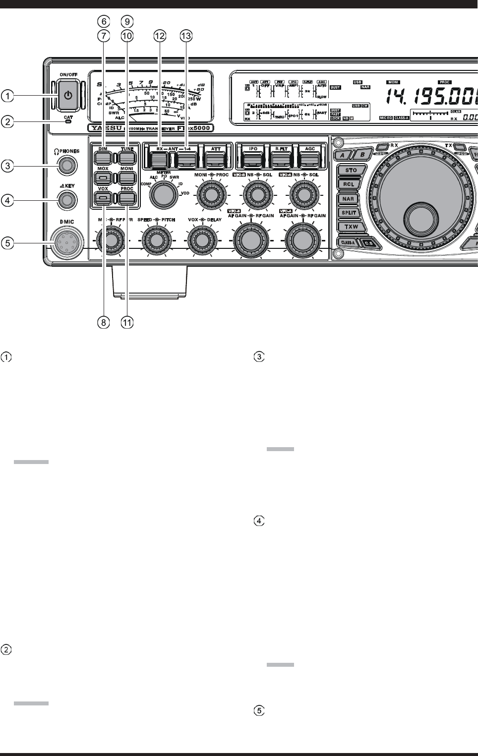
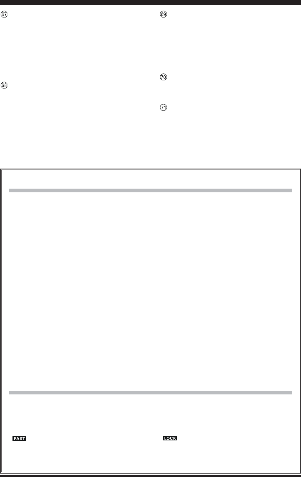
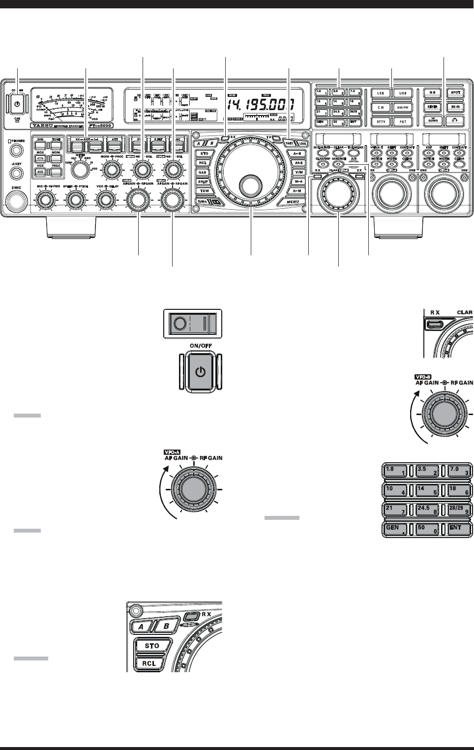
[POWER] Switch
Press and hold in this switch for two seconds to turn
the transceiver on, after first setting the rear panel
[MAIN POWER] switch to the “I” position. Press
and hold in this switch for two seconds, similarly, to
turn the transceiver off. If the rear panel [MAIN
POWER] switch is set to the “O” position, the front
panel [POWER] switch will not function.
ADVICE:
If you press this switch briefly while the transceiver
is turned on, the transceiver’s audio will be muted
for three seconds.
This is the actual power On/Off switch for turning
on the transceiver. When the rear panel [MAIN
POWER] switch is set to the “I” position, power
is supplied to the OCXO to stabilize the reference
oscillator, and the remainder of the transceiver is
set in a “stand-by” mode, awaiting the command
for the transceiver to switch on via the front panel
[POWER] switch. For further information on the
rear panel [MAIN POWER] switch, please see the
discussion on page ??.
CAT Indicator
This LED indicator will flash red when the transmit
and receive serial CAT command signals are being ex-
changed.
ADVICE:
You may disable the LED function (flashes in conjunc-
tion with CAT command) via Menu item “031 GEnE
CAT IND.” See page ??? for details.
PHONES Jack
A 1/4-inch, 3-contact jack accepts either monaural or
stereo headphones with 2- or 3-contact plugs. When a
plug is inserted, the loudspeaker is disabled. With ste-
reo headphones such as the optional YH-77STA, you
can monitor both VFO-A and VFO-B receiver chan-
nels at the same time during Dual Receive operation.
NOTE:
When wearing headphones, we recommend that you
turn the AF Gain levels down to their lowest settings
before turning power on, to minimize the impact on
your hearing caused by audio “pops” during switch-on.
KEY Jack
This 1/4-inch, 3-contact jack accepts a CW key or keyer
paddles (for the built-in electronic keyer), or output
from an external electronic keyer. Pinout is shown on
page 15. Key up voltage is 5 V, and key down current
is 1 mA. This jack may be configured for keyer, “Bug,”
“straight key,” or computer keying interface operation
via Menu item “054 A1A F-TYPE” (see page ???).
There is another jack with the same name on the rear
panel, and it may be configured independently for In-
ternal Keyer or pseudo-straight-key operation.
NOTE:
You cannot use a 2-contact plug in this jack (to do so
produces a constant “key down” condition).
Microphone Connector
This 8-pin jack accepts input from a microphone uti-
lizing a traditional YAESU HF-transceiver pinout.
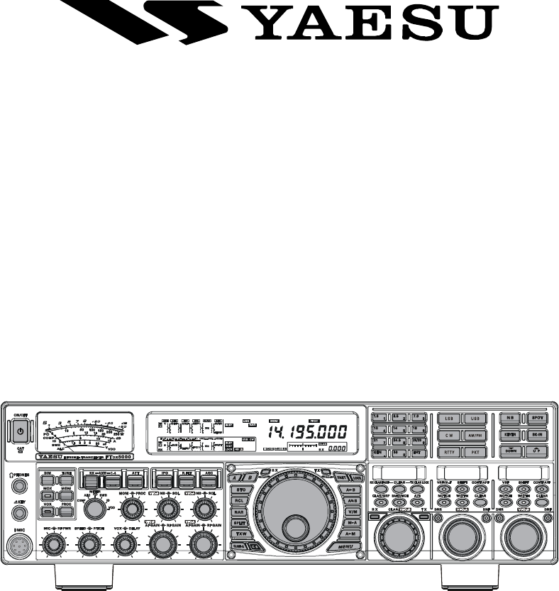
FRONT PANEL CONTROLS & SWITCHES
Page 17FTDX5000 OPERATING MANUAL
[DIM] Switch
Press this button to lower the illumination intensity of
the analog meter and the frequency display. Press it
once more to restore full brightness.
ADVICE:
Menu Items “008 diSP DIM MTR” and “009 diSP
DIM VFD” allow you to configure the dimming lev-
els for the analog meter and the frequency display in-
dependently, so you can customize the brightness lev-
els.
[MOX] Switch
Pressing this button engages the PTT (Push to Talk)
circuit, to activate the transmitter (the LED inside this
button will glow red). It must be turned off (the red
LED will be off) for reception. This button replicates
the action of the Push to Talk (PTT) switch on the mi-
crophone. When engaging the [MOX] button (the LED
inside this button glows red) or otherwise causing a
transmission to be started, be certain you have either
an antenna or 50-Ohm dummy load connected to the
selected Antenna jack.
[VOX] Switch
This button enables automatic voice-actuated transmit-
ter switching in the SSB, AM, and FM modes. While
activated, the LED inside this button glows red. The
controls affecting VOX operation are the front panel’s
[VOX] and [DELAY] knobs. By proper adjustment of
these controls, hands-free voice-actuated operation is
possible.
[TUNE] Switch
This is the on/off switch for the FTDX5000’s Auto-
matic Antenna Tuner.
Pressing this button momentarily places the antenna
tuner in line between the transmitter final amplifier and
the antenna jack (“ ” icon will appear in the dis-
play). Reception is not affected.
Pressing and holding in this button for 1/2 second, while
receiving in an amateur band, activates the transmitter
for a few seconds while the automatic antenna tuner
rematches the antenna system impedance for minimum
SWR. The resulting setting is automatically stored in
one of the antenna tuner’s 100 memories, for instant
automatic recall later when the receiver is tuned near
the same frequency.
Pressing this button briefly, while the Tuner is engaged,
will take the Automatic Antenna tuner out of the trans-
mit line.
NOTE:
When the Automatic Antenna Tuner is tuning itself, a
signal is being transmitted. Therefore, be absolutely
certain that an antenna or dummy load is connected to
the selected antenna jack before pressing and holding
in the [TUNE] button to start antenna tuning.
[MONI] (Monitor) Switch
This button enables the transmit monitor in all modes.
While activated, the “ ” icon appears in the dis-
play. Adjustment of the Monitor level is accomplished
using the [MONI] knob.
ADVICE:
When using headphones, the Monitor is highly useful
for making adjustments to the Parametric Equalizer or
other voice quality adjustments, because the voice qual-
ity heard in the headphones is such a “natural” repro-
duction of the transmitted audio quality.
[PROC] (Processor) Switch
This button enables the Speech Processor for SSB
transmission. While activated, the “ ” icon appears
in the display. Adjustment of the Processor level is ac-
complished using the [PROC] knob.
ADVICE:
The Speech Processor is a tool for increasing the
average power output through a compression tech-
nique. However, if the [PROC] knob is advanced
too far, the increase in compression becomes
counter-productive, as intelligibility will suffer. We
recommend that you monitor the sound of your sig-
nal using the Monitor (with headphones).
When the optional DMU-2000 Data Management
Unit is connected, you may use the Audio Scope/
Oscilloscope page to help you adjust the setting of
the compression level of the Speech Processor for
optimum performance using your voice and micro-
phone.
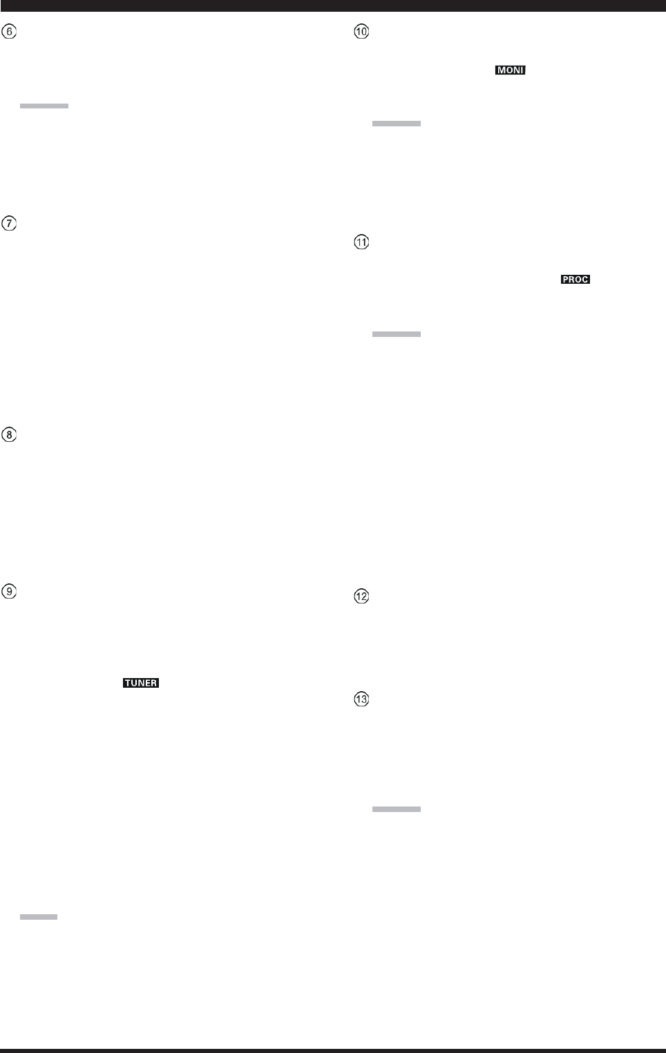
[RX ANT] Switch
Press this button to use the RX ANT jack on the rear
panel while receive.
The “RX” icon appears in the display when the RX
ANT is used.
[ANT 1-4] Switch
Move this knob up and down to select one of the ANT
1 through 4 jack on the rear panel, and allows conve-
nient antenna switching at the move of knob. The se-
lected antenna jack is indicated in the ANT column of
the Block Diagram Display on the display.
ADVICE:
Press this knob briefly to select the ANT 1 jack for
quick selection.
FRONT PANEL CONTROLS & SWITCHES
Page 18 FTDX5000 OPERATING MANUAL
FRONT PANEL CONTROLS & SWITCHES
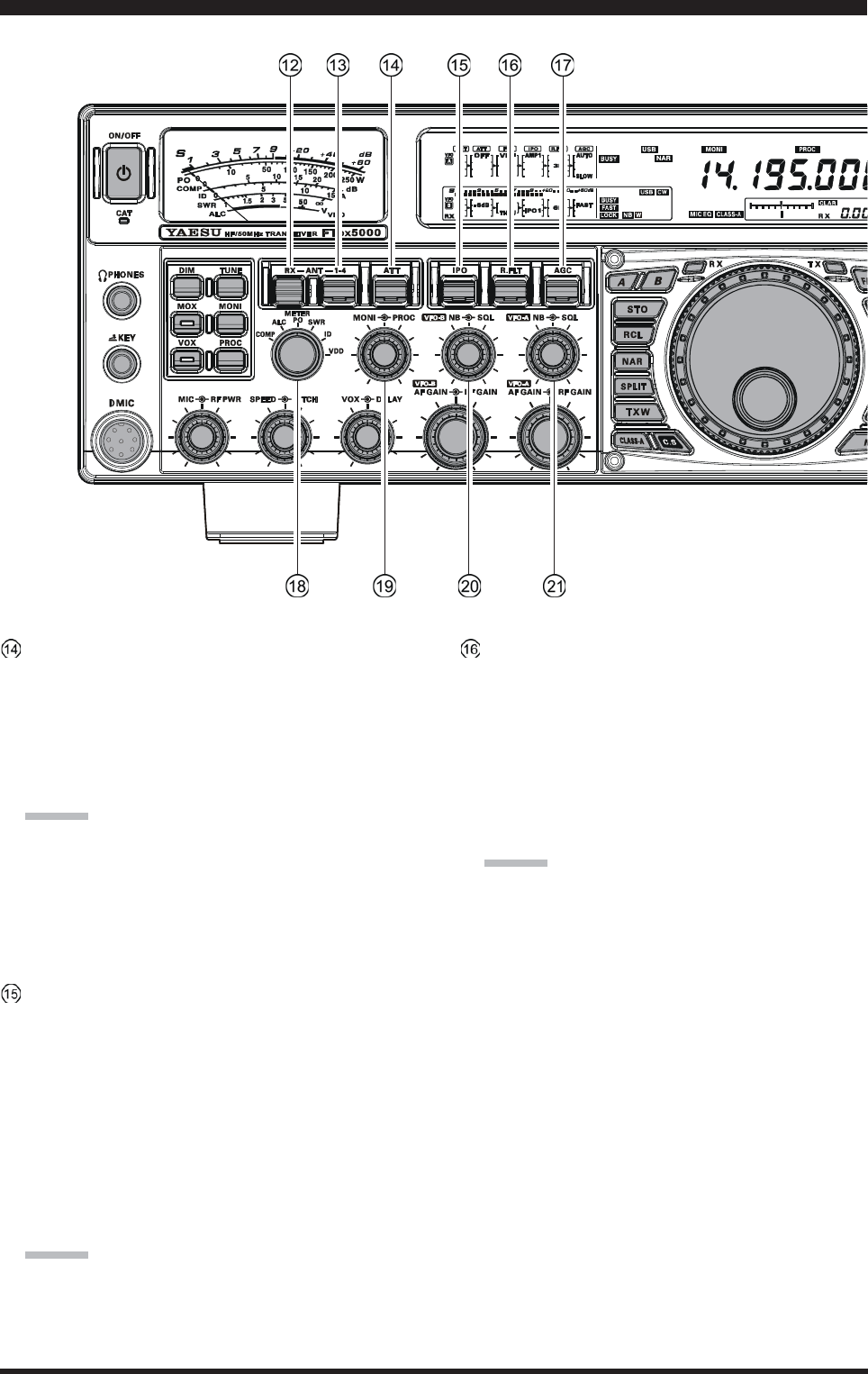
[ATT] Switch
Move this knob up and down to select the degree of
attenuation, if any, to be applied to the receiver input.
Available selections are “–6 dB”, “–12 dB”, “–18 dB”,
or “OFF”, and the selected attenuation level appears
in the ATT column of the Block Diagram Display on
the display.
ADVICE:
Press this knob briefly to select the attenuation level
to “OFF” for quick selection.
The Attenuator may be used in conjunction with
the [IPO] switch to provide two stages of signal
reduction when an extremely strong signal is being
received.
[IPO]
(I
NTERCEPT
P
OINT
O
PTIMIZATION
)
Switch
Move this knob up and down to select the optimum
front end characteristics of the receiver circuit for a
very strong-signal environment. Available selections
are “AMP 1”, “AMP 2”, “IPO 1”, or “IPO 2”.
Normally, this selection is set to “AMP1”. If you want
to increase the sensitivity, this selection selects to
“AMP2”. When this selection is set to “IPO1”, the IPO
is improved. When this selection is set to “IPO2”, by-
passes the RF preamplifier, yielding direct feed to the
first mixer. As a result, the IPO is improved more.
ADVICE:
Press this knob briefly to select the IPO setting to
“AMP1” for quick selection.
“IPO 2” selection can not selet in VFO-B.
[R.FLT] Switch
Move this knob up and down to select the bandwidth
for the first IF Roofing Filter. Available selections are
“300 Hz”, “600 Hz”, “3 kHz”, “6 kHz”, “15 kHz”, or
“AUTO” (“300 Hz” and “600 Hz” are select only in
VFO-A, additionally, “300 Hz” is option, except MP
version), and the selected bandwidth appears in the
R.FLT column of the Block Diagram Display on the
display.
ADVICE:
Press this knob briefly to select to “AUTO” for
quick selection.
Because the roofing filter is in the first IF, the pro-
tection it provides against interference is quite sig-
nificant. When set to “AUTO”, the SSB bandwidth
is 6 kHz, while CW is 3 kHz, and FM/RTTY are
15 kHz. On a crowded SSB band, however, you
may wish to select the 3 kHz filter, for the maxi-
mum possible interference rejection.
Page 19FTDX5000 OPERATING MANUAL
FRONT PANEL CONTROLS & SWITCHES
[AGC] Switch
Move this knob up and down to select the AGC char-
acteristics (receiver-recovery time) for the receiver.
Available selections are FAST, MID, SLOW, or AUTO,
and the selected receiver-recovery time appears at the
AGC column of the Block Diagram Display on the dis-
play.
Hold up or hold down this knob for two seconds to
disable the AGC (for testing or weak-signal reception).
ADVICE:
Press this knob briefly to select to AUTO for quick
selection.
If the AGC is set to disabled by holding up or down
the [AGC] knob, the S-meter will no longer de-
flect. Additionally, you will likely encounter dis-
tortion on stronger signals, as the IF amplifiers and
the following stages are probably being overloaded.
[METER] Switch
This control switch determines the function of the meter
during transmission.
COMP: Indicates the speech compressor level (SSB
mode only).
ALC: Indicates the relative ALC voltage.
PO: Indicates the average power output level.
SWR: Indicates the Standing Wave Ratio (Forward:
Reflected).
ID: Indicates the final amplifier drain current.
VDD: Indicates the final amplifier drain voltage.
[MONI] [PROC] Knobs
[MONI] Knob
The inner [MONI] knob adjust the audio level of
the transmit RF monitor during transmission (rela-
tive to the AF GAIN control), when activated by
the [MONI] button.
[PROC] Knob
The outer [PROC] knob sets the compression (in-
put) level of the transmitter Speech Processor in
the SSB, AM, and FM modes, when activated by
the [PROC] button.
ADVICE:
The SUB DISPLAY-
III
will show the relative com-
pression level of the Speech Processor for 3 sec-
onds whenever the outer [PROC] knob is turned.
You may disable this feature (displaying the rela-
tive compression level) via Menu item “015 diSP
LVL IND.” See page 113 for details.
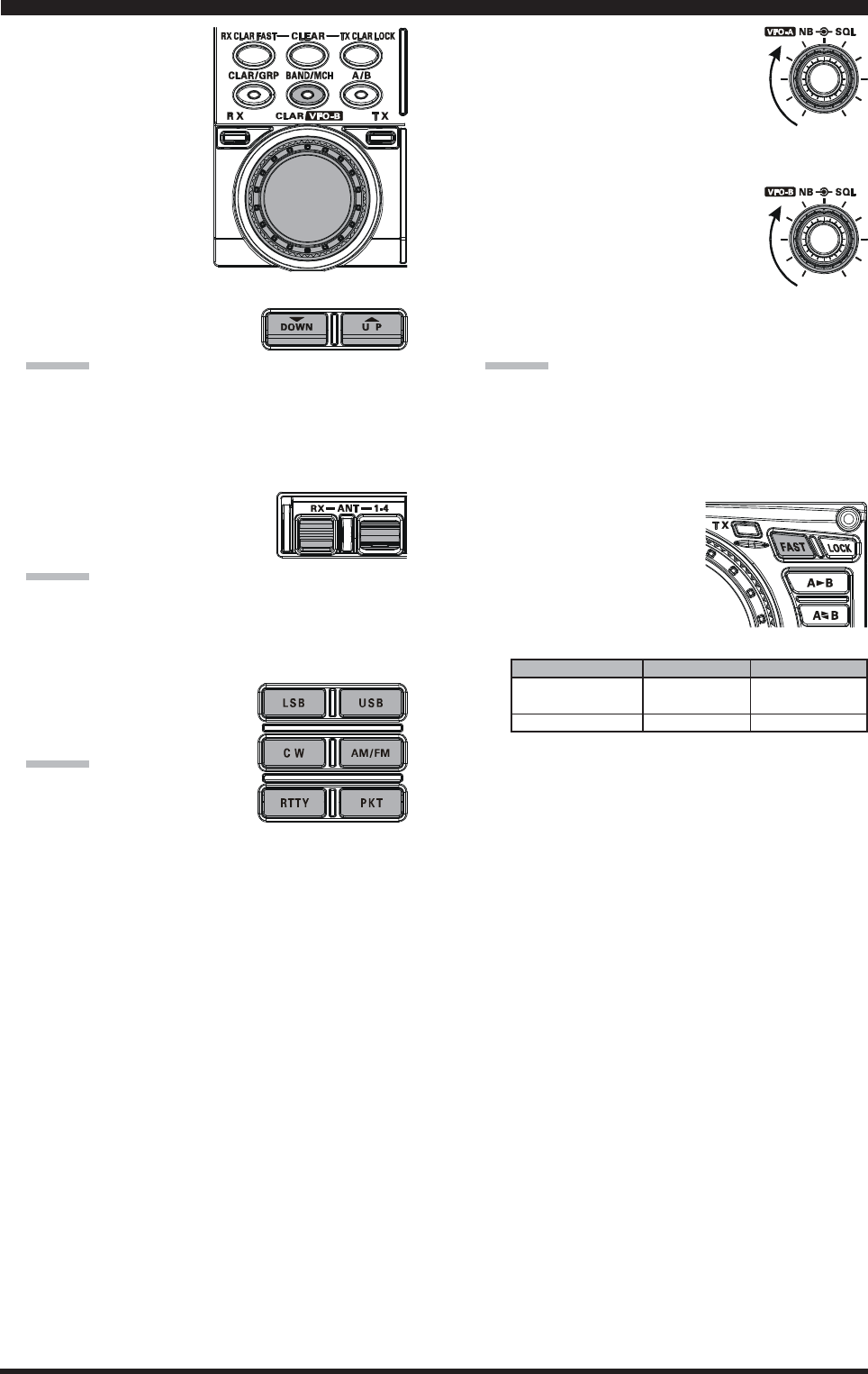
(VFO-B) [NB][SQL] Knobs
[NB] Knob
The inner [NB] knob adjusts the VFO-B noise
blanking level when the (analog) IF noise blanker
is activated by pressing the [NB] button.
[SQL] Knob
The outer [SQL] knob sets the signal level thresh-
old at which the VFO-B receiver audio is muted, in
all modes. It is very useful during local rag-chews,
to eliminate noise between incoming transmissions.
This control is normally kept fully counter-clock-
wise (off), except when scanning and during FM
operation.
(VFO-A) [NB][SQL] Knobs
[NB] Knob
The inner [NB] knob adjusts the VFO-A noise
blanking level when the (analog) IF noise blanker
is activated by pressing the [NB] button.
[SQL] Knob
The outer [SQL] knob sets the signal level thresh-
old at which the VFO-A receiver audio is muted, in
all modes. It is very useful during local rag-chews,
to eliminate noise between incoming transmissions.
This control is normally kept fully counter-clock-
wise (off), except when scanning and during FM
operation.
Page 20 FTDX5000 OPERATING MANUAL
FRONT PANEL CONTROLS & SWITCHES
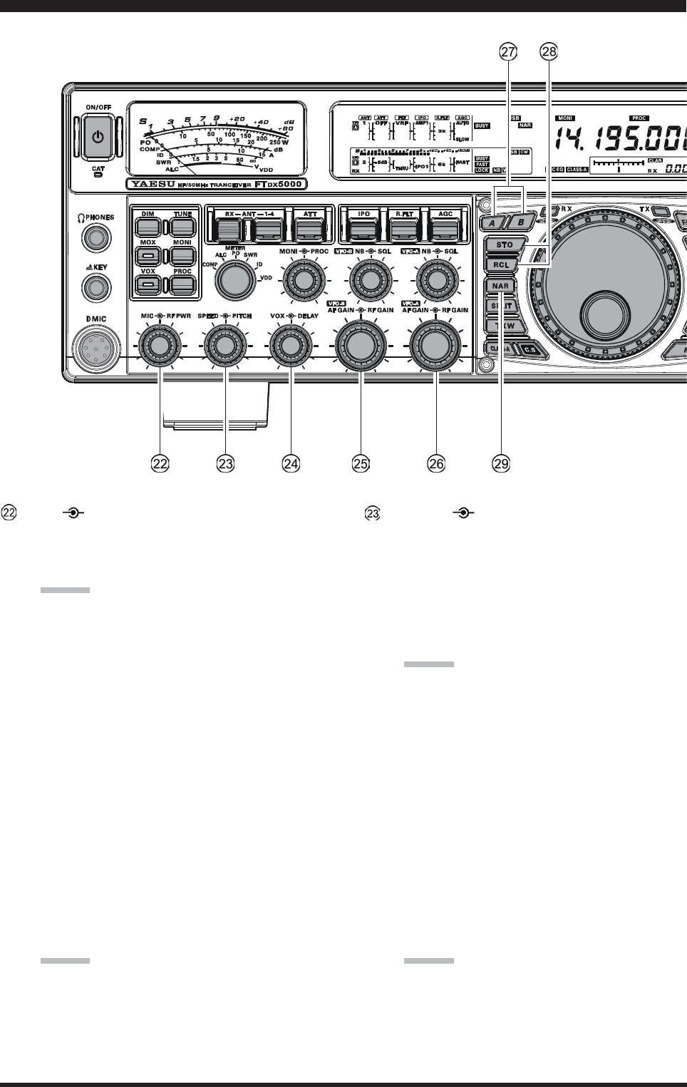
[MIC] [RF PWR] Knobs
[MIC] Knob
The inner [MIC] knob adjusts the microphone in-
put level for (non-processed) SSB transmission.
ADVICE:
If you adjust the MIC Gain while speaking in a
somewhat-louder-than-normal voice level,
watch the ALC level and adjust the MIC Gain
so that the ALC reaches just to the right edge of
the ALC scale. Then, when you speak in a more
normal voice level, you’ll be certain not to be
over-driving the mic amplifier stage.
The SUB DISPLAY-
III
will show the relative
Microphone Gain level for 3 seconds whenever
the inner [MIC] knob is turned.
You may disable this feature (displaying the rela-
tive Microphone Gain level) via Menu item “015
diSP LVL IND.” See page 113 for details.
[RF PWR] Knob
The outer [RF PWR] knob is the main RF Power
output control for the transceiver, active in all op-
erating modes. Clockwise rotation increases the
power output. Adjust this control for the desired
power output from the FTDX5000.
ADVICE:
The SUB DISPLAY-
III
will show the RF Power
Output for 3 seconds whenever the outer [RF
PWR] knob is turned.
You may disable this feature (displaying the RF
Power Output) via Menu item “015 diSP LVL
IND.” See page 113 for details.
[SPEED] [PITCH] Knobs
[SPEED] Knob
The inner [SPEED] knob adjusts the keying speed
of the internal CW keyer (4 ~ 60 WPM). Clock-
wise rotation increases the sending speed.
When turning this knob while pressing the
[KEYER] button, the Sub (VFO-B) frequency dis-
play shows the keying speed.
ADVICE:
The SUB DISPLAY-
III
will show the keying speed
for 3 seconds whenever the inner [SPEED] knob
is turned.
You may disable this feature (displaying the key-
ing speed) via Menu item “015 diSP LVL IND.”
See page ??? for details.
[PITCH] Knob
The outer [PITCH] knob selects your preferred CW
tone pitch (from 300 ~ 1050 Hz, in 50 Hz incre-
ments). The Tx sidetone, receiver IF passband, and
display offset from the BFO (carrier) frequency are
all affected simultaneously. The Pitch control set-
ting also affects the operation of the CW Tuning
Indicator, as the center frequency of the CW Tun-
ing Indicator will follow the setting of this control.
ADVICE:
The SUB DISPLAY-
III
will show the CW tone
pitch frequency for 3 seconds whenever the outer
[PITCH] knob is turned.
You may disable this feature (displaying the CW
tone pitch frequency) via Menu item “015 diSP
LVL IND.” See page ??? for details.
Page 21FTDX5000 OPERATING MANUAL
FRONT PANEL CONTROLS & SWITCHES
[VOX] [DELAY] Knobs
[VOX] Knob
The inner [VOX] knob sets the gain of the VOX
circuit, to set the level of microphone audio needed
to activate the transmitter during voice operation
while the [VOX] switch is engaged. The [VOX]
switch must be switched “ON” to engage the VOX
circuit.
[DELAY] Knob
The outer [DELAY] knob sets the hang time of the
VOX circuit for voice operation and keying delay
for CW operation.
During voice operation, this knob sets the hang time,
between the moment you stop speaking, and the
automatic switch from transmit back to receive.
Adjust this for smooth VOX operation, so the re-
ceiver is only activated when your transmission is
ended and you wish to receive.
For CW operation, this knob sets the keying delay,
between the moment you stop sending, and the au-
tomatic switch from transmit back to receive dur-
ing “Semi-break-in” operation. Adjust this just long
enough to prevent the receiver from being restored
during word spaces at your preferred sending speed.
ADVICE:
The SUB DISPLAY-
III
will show the hang time of
the VOX circuit for 3 seconds whenever the outer
[DELAY] knob is turned.
You may disable this feature (displaying the hang
time of the VOX circuit) via Menu item “015 diSP
LVL IND.” See page ??? for details.
(VFO-B) [AF GAIN][RF GAIN] Knobs
[AF GAIN] Knob
The inner [AF GAIN] knob sets the VFO-B
receiver’s audio volume level. Typically, you will
operate with this control set between the 9 o’clock
and 10 o’clock positions.
[RF GAIN] Knob
The outer [RF GAIN] knob is the VFO-B receiver’s
RF gain control, which adjusts the gain of the VFO-
B receiver’s RF and IF amplifier stages. This con-
trol is normally left in the fully clockwise position.
(VFO-A) [AF GAIN][RF GAIN] Knobs
[AF GAIN] Knob
The inner [AF GAIN] knob sets the VFO-A
receiver’s audio volume level. Typically, you will
operate with this control set between the 9 o’clock
and 10 o’clock positions.
[RF GAIN] Knob
The outer [RF GAIN] knob is the VFO-A receiver’s
RF gain control, which adjusts the gain of the VFO-
A receiver’s RF and IF amplifier stages. This con-
trol is normally left in the fully clockwise position.
[A], [B] Switches
Pressing the [A] or [B] button will illuminate the re-
spective indicator imbedded within the switch, allow-
ing adjustment of the major functions (such as mode
and band selection etc) on the VFO-A or VFO-B band.
Usually, the [A] button glow red, signifying that the
VFO-A is being adjusted. Similarly, pressing the [B]
button will cause its indicator glow orange, signifying
VFO-B adjustment.
ADVICE:
The [A]/[B] switch’s function is effect for following
switches:
y[RX ANT] switch
y[ANT 1-4] switch
y[ATT] switch
y[IPO] switch
y[R.FLT] switch
y[AGC] switch
y[NAR] switch
y[BAND] switches
y[MODE] switches
y[NB] switch
y[RX ANT] switch
QMB (Quick Memory Bank) Switches
[STO] (Store) Button
Pressing this button copies operating information
(frequency, mode, bandwidth, and also repeater di-
rection/shift frequency and CTCSS functions on the
FM mode) into consecutive QMB Memories.
[RCL] (Recall) Button
Pressing this button recalls one of up to five Quick
Memory Bank memories for operation.
[NAR] (Narrow) Switch
This button is used to set the DSP (digital) filters to
narrow bandwidth. The default values are follows:
Ú:You may enable to adjust the bandwidth by the
[WIDTH] knob.
OFF
2.4 kHzÚ
(1.8 kHz - 4.0 kHz / 16 steps)
2.4 kHzÚ
(500 Hz - 2.4 kHz / 7 steps)
500 HzÚ
(500 Hz - 2.4 kHz / 7 steps)
500 HzÚ
(500 Hz - 2.4 kHz / 7 steps)
25 kHz
(±5.0 kHz Deviation)
9 kHz
25 kHz
(±5.0 kHz Deviation)
ON
1.8 kHzÚ
(200 Hz - 1.8 kHz / 9 steps)
500 HzÚ
(50 Hz - 500 Hz / 10 steps)
300 HzÚ
(50 Hz - 500 Hz / 10 steps)
300 HzÚ
(50 Hz - 500 Hz / 10 steps)
12.5 kHz
(±2.5 kHz Deviation)
6 kHz
12.5 kHz
(±2.5 kHz Deviation)
MODE
LSB/USB
CW
RTTY
(LSB)
PKT
(LSB/USB)
PKT
(FM)
AM
FM
NAR SWITCH
Page 22 FTDX5000 OPERATING MANUAL
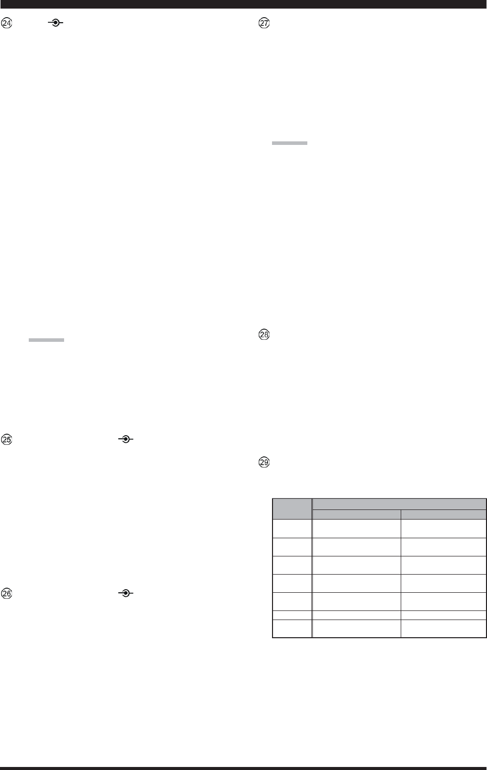
FRONT PANEL CONTROLS & SWITCHES
[SPLIT] Switch
Pressing this button to activate split frequency opera-
tion between the VFO-A, used for reception, and the
VFO-B, used for transmission. If you press and hold
in this button for two seconds, the “Quick Split” fea-
ture will be engaged, whereby the VFO-B will auto-
matically be set to a frequency 5 kHz higher than the
VFO-A frequency with same operating mode, and the
transceiver will be placed in the Split mode.
[TXW] (TX Watch) Switch
Pressing this button lets you monitor the transmit fre-
quency when split frequency operation is engaged.
Release the button to return to normal operation.
[CLASS-A] Switch
Pressing this button engages the Class-A capability for
the transmitter. The power output will be reduced to a
maximum of 75 Watts, however, the Class-A opera-
tion provides an ultra-clean SSB wave-form. When
Class-A operation is engaged, the “CLASS-A” icon
appears in the display. Press this button once more to
return to Class-AB operation at a maximum power
output of 200 Watts; the “CLASS-A” icon disappears
to confirm Class-AB operation.
ADVICE:
You may adjust the bias level between “Class-AB” and
“Class-A” via Menu item “015 tGEn BAIS”. See page
??? for details.
[C.S] Switch
Press this button briefly to recall a favorite Menu Se-
lection directly.
To program a Menu selection as the short-cut, press
the [MENU] button to enter the Menu, then select the
Menu item you want to set as the short-cut. Now press
and hold in the [C.S] button for two seconds; this will
lock in the selected Menu item as the short-cut.
(VFO-A)[RX] Indicator/Switch
This button, when pressed, engages the VFO-A re-
ceiver; the LED inside this button will glow green when
the VFO-A receiver is active.
When the VFO-A receiver is active, pressing this but-
ton briefly will mute the receiver, and the indicator will
blink. Pressing the button once more will restore re-
ceiver operation, and the indicator will glow green
steadily.
(VFO-A)[TX] Indicator/Switch
When this button is pressed, the LED inside this but-
ton will glow red, and the transmitter will be engaged
on the same frequency and mode as set up for the VFO-
A (subject to any Clarifier offset, of course).
ADVICE:
If this indicator is not illuminated, it means that the
VFO-B TX indicator has been selected (it will be glow-
ing red). In this case, transmission will be effected on
the frequency and mode programmed for the VFO-B.
Page 23FTDX5000 OPERATING MANUAL
FRONT PANEL CONTROLS & SWITCHES
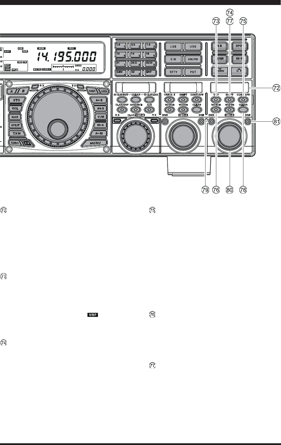
Main Tuning Dial Knob
This large knob adjusts the operating frequency of the
VFO-A or a recalled memory. Clockwise rotation of
this knob increases the frequency. Default tuning in-
crements are 10 Hz (100 Hz in AM and FM modes);
when the [FAST] button is pressed, the tuning steps
increase. The available steps are:
ADVICE::
::
:
The tuning steps for the Main Tuning Dial knob are
set, at the factory, to 10 Hz per step. Via Menu item
“118 tun DIAL STEP,” however, you may change this
setting from 10 Hz to 5 Hz or 1 Hz instead. When press
the [FAST] button, the tuning step change to 100 Hz.
[FAST] Switch
Pressing this button will change the VFO-A’s tuning
step to 100 Hz.
When this function is activated, the “ ” icon ap-
pears in the display.
[LOCK] Switch
This button toggles locking of the Main Tuning Dial
knob, to prevent accidental frequency changes. When
the button is active, the Main Tuning Dial knob can
still be turned, but the VFO-A frequency will not
change, and the “ ” icon appears in the display.
[A
X
B] Switch
Press this button briefly to transfer data from the VFO-
A frequency (or a recalled memory channel) to the
VFO-B, overwriting any previous contents in the VFO-
B. Use this button to set both VFO-A and VFO-B re-
ceivers to the same frequency and mode.
[A
X
W
B] Switch
Pressing this button momentarily exchanges the con-
tents of the Main band (VFO-A) (or a recalled memory
channel) and the Sub band (VFO-B).
[V/M] Switch
This button toggles VFO-A receiver operation between
the memory system and the VFO. Either “ ” or
“” will be displayed to the under the main fre-
quency display field to indicate the current selection.
If you have tuned off of a Memory channel frequency
(MT), pressing this button returns the display to the
original memory contents (MR), and pressing it once
more returns operation to the VFO-A (no icon).
OPERATING MODE
LSB/USB/CW/RTTY/PKT(SSB)
AM/FM/PKT(FM)
Numbers in parentheses indicate steps when the [FAST] button is On.
1 STEP
10 Hz (100 Hz)
100 Hz (1 kHz)
1 DIAL ROTATION
10 kHz (100 kHz)
100 kHz (1 MHz)
[M
X
A] Switch
Pressing this button momentarily displays the contents
of the currently-selected memory channel for three sec-
onds.
Holding this button in for 2 seconds copies the data
from the currently-selected memory to the VFO-A, as
two beeps sound. Previous data in the VFO-A will be
overwritten.
[A
X
M] Switch
Pressing and holding in this button for 1/2 second (un-
til the double beep) copies the current operating data
from the VFO-A into the currently selected memory
channel, overwriting any previous data stored there.
See page ??? for details.
Also, pressing and holding in this button after recall-
ing a memory, without first retuning, causes the memory
channel to be “masked,” and repeating the process re-
stores the masked memory.
[MENU] Switch
This button is used for gaining access to the Menu sys-
tem, for configuring various transceiver characteris-
tics. Menu operation is described in detail, in this
manual, beginning on page ???.
IMPORTANT NOTE:
Pressing this button briefly activates the Menu, and
the Menu items will appear on the SUB DISPLAYs;
once you are finished, you must press and hold in the
[MENU] button for two seconds to save any configu-
ration changes (momentarily pressing the [MENU]
button to exit will not save the changes).
[BAND] Keys
These buttons allow one-touch selection of the desired
amateur band (1.8 ~ 50 MHz).
What’s more, these buttons may be used for direct en-
try of a desired operating frequency during VFO op-
eration.
[MODE] Switches
Pressing one of these buttons, selects the operating
mode. Repeated presses of a particular switch will
toggle to the alternate mode, or step through the avail-
able selections, as shown in the chart below.
Page 24 FTDX5000 OPERATING MANUAL
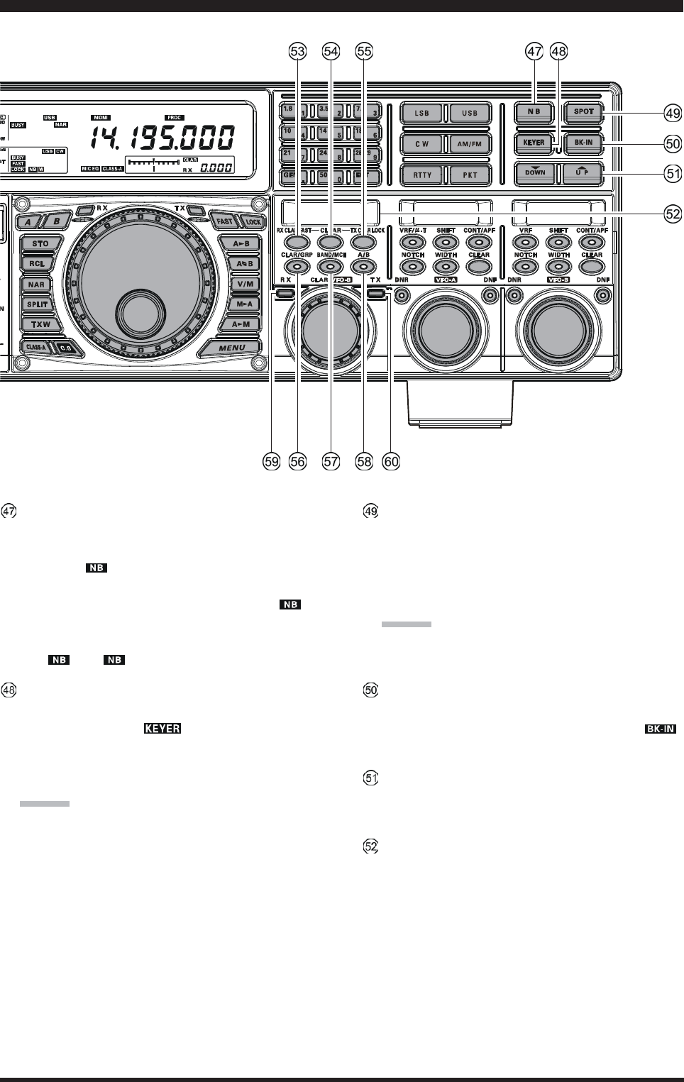
[NB] Switch
This button turns the IF Noise Blanker on and off.
Press this button briefly to reduce a short-duration pulse
noise; the “ ” icon will appear in the display.
Press and hold in this button for one second to reduce
a longer-duration man-made pulse noise; the “ W”
icon will appear in the display.
Press this button again to disable the noise blanker;
the “ ” or “ W” icon will disappear.
[KEYER] Switch
This button toggles the internal CW keyer on and off.
While activated, the “ ” icon appears in the dis-
play. The keyer sending speed is adjusted via the front
panel’s [SPEED] knob and the CW Hang Time is ad-
justed via the Menu item “044 A1A DELAY”.
ADVICE:
When press an holding this button to shows the keying
speed on the SUB DISPLAY-
III
.
You may disable this feature (displaying the keying
speed) via Menu item “015 diSP LVL IND.” See page
??? for details.
[SPOT] Switch
This button turns on the CW receiver spotting tone; by
matching the SPOT tone to that of the incoming CW
signal (precisely the same pitch), you will be “zero
beating” your transmitted signal on to the frequency of
the other station.
ADVICE:
The SUB DISPLAY-
III
will indicate the offset tone
frequency when this button is pressed.
[BK-IN] Switch
This button turns the CW break-in capability on and
off. While the CW break-in is activated, the “ ”
icon appears in the display.
[T(DOWN)]/[S(UP)] Switches
These buttons adjust the operating frequency of the
VFO or a recalled memory in 100 kHz step.
SUB DISPLAY-I
This LCD display shows the VFO-B frequency, and it
indicates the Menu List while the Menu Mode is ac-
tive.
FRONT PANEL CONTROLS & SWITCHES
Page 25FTDX5000 OPERATING MANUAL
[RX CLAR(FAST)] Switch
The function of this button is different by the setting of
the [A/B] button (described later).
When the imbedded LED of the [A/B] button is turned
off, pressing this button activates the RX Clarifier, to
allow offsetting the VFO-A receiving frequency tem-
porarily. Press this button once more to return the Main
receiver to the frequency shown on the main frequency
display field; the Clarifier offset will still be present,
though, in case you want to use it again. To cancel the
Clarifier offset, press the [CLEAR] button.
When the imbedded LED of the [A/B] button glows
orange, pressing this button will change the VFO-B’s
tuning step to 100 Hz.
When this function is activated, the “ ” icon ap-
pears in the display.
[CLEAR] Switch
Pressing this button clears out any frequency offset you
have programmed into the Clarifier register (thereby
setting the offset to “Zero”).
[TX CLAR/LOCK] Switch
The function of this button is different by the setting of
the [A/B] button (described later).
When the imbedded LED of the [A/B] button is turned
off, pressing this button activates the TX Clarifier, to
allow offsetting the VFO-A transmit frequency tempo-
rarily. Press this button once more to return the trans-
mitter to the VFO-A frequency shown on the main fre-
quency display field; the Clarifier offset will still be
present, though, in case you want to use it again. To
cancel the Clarifier offset, press the [CLEAR] button.
When the imbedded LED of the [A/B] button glows
orange, this button toggles locking of the
[CLAR(VFO-B)] knob, to prevent accidental fre-
quency changes. When this button is active, the
[CLAR(VFO-B)] knob can still be turned, but the
VFO-B frequency will not change, and the “ ”
icon appears in the display.
[CLAR/GRP] Switch
This button has two functions.
When press this button briefly, the [CLAR/VFO-B]
knob will be enabled for the purpose of unilizing the
[CLAR/VFO-B] knob as an “offset tuning” control to
allow tuning away from the VFO-A, and the imbedded
LED of the [CLAR/GRP] button is glows red.
When press and hold this button for one second, al-
lows you to select the memory group using the
[CLAR(VFO-B)] knob, and the imbedded LED of the
[CLAR/GRP] button is glows yellow.
[BAND(MCH)] Switch
This button has two functions.
When press this button briefly, allows you to select
the VFO-A operating band (Amateur bands) using the
[CLAR(VFO-B)] knob, and the LED inside of the
[CLAR/GRP)] button is glows red.
When press and hold this button for one second, al-
lows you to select the memory channel using the
[CLAR(VFO-B)] knob, and the imbedded LED of the
[CLAR/GRP] button is glows yellow.
[A/B] Switch
This button determines whether the actions of the
[CLAR(VFO-B)] knob will be applied to the VFO-A
or the VFO-B.
Pressing this button once causes the imbedded LED of
this button glows yellow; in this case, rotation of the
[CLAR(VFO-B)] knob affects operation on the VFO-
B (tuning, etc.). Pressing this button once more causes
the imbedded LED of this button to turn off; in this
instance, rotation of the [CLAR(VFO-B)] knob affects
operations associated with the VFO-A (Clarifier func-
tion, etc.).
(VFO-B)[RX] Indicator/Switch
This is the button that turns the VFO-B receiver “On”
and “Off”. When this button is pressed to make the
VFO-B receiver active, the imbedded LED will glows
green. Pressing this button again will disable this re-
ceiver, and the imbedded green LED will turn off.
(VFO-B)[TX] Indicator/Switch
This is the button that turns the VFO-B transmitter “On”
and “Off”. When this button is pressed to transfer trans-
mitter control to the VFO-B frequency and mode, the
imbedded LED will glows red. Pressing this button
once more will transfer frequency/mode control back
to theVFO-A side, and the red LED imbedded within
this button will turn off.
FRONT PANEL CONTROLS & SWITCHES
Page 26 FTDX5000 OPERATING MANUAL
[CLAR(VFO-B)] Knob
The function of this knob is different by the setting of
three switches located above this knob. See next page
for details.
SUB DISPLAY-II
This LCD display shows the character of the VFO-A
receiver’s DSP function selected by the five buttons
located below of this display, and the (VFO-
A)[SELECT] knob located below this window works
as an adjustment knob that displayed to this window.
Furthermore, when the Menu Mode is activated, this
LCD display indicates the Menu item.
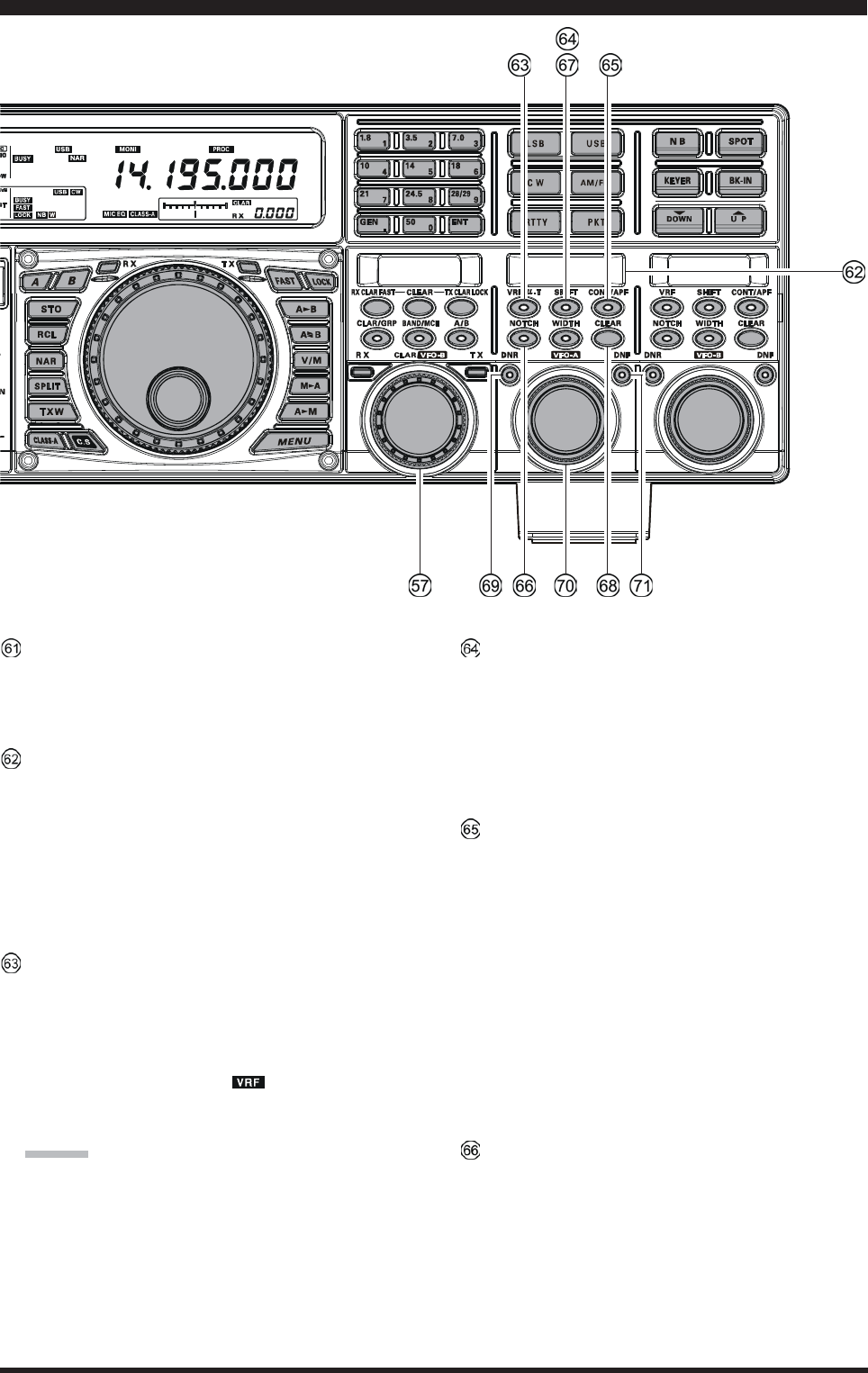
(VFO-A)[VRF/-T] Switch
This button turns the VFO-A receiver’s contour filter
“on” and “off”, and allows you to adjust the center fre-
quency of the VRF filter by the (VFO-A)[SELECT]
knob. While activated, the red imbedded LED in this
button will light up, and the “ ” icon will appear in
the FLT column of the Block Diagram Display on the
display.
ADVICE:
When the optional RF Tuning Kit is connected, press-
ing this button will engage the -Tuning filter. The
Tuning Kit provides much better RF selectivity than
any other RF filter in the Amateur industry, yielding
outstanding protection from high RF levels not far re-
moved from the current operating frequency.
(VFO-A)[SHIFT] Switch
Pressing this button allows you to move the IF DSP
bandwidth of VFO-A “higher” or “lower” by the (VFO-
A)[SELECT] knob. When the IF passband is shifted,
the red LED imbedded in this button will light up. To
the contrary, when the IF passband is just centered, the
red LED imbedded in this button turns off.
(VFO-A) [CONT/APF] Switch
In the SSB, AM, and FM modes, this button turns the
VFO-A receiver’s contour filter “on” and “off”, and
allows you to adjust the center frequency of the con-
tour filter by the (VFO-A)[SELECT] knob. When the
contour filter is activated, the red imbedded LED in
this button will light up.
In the CW mode, this button turns the VFO-A receiver’s
APF (Audio Peak Filter) “on” and “off”, and allows
you to adjust the bandwidth of the APF filter by the
(VFO-A)[SELECT] knob. When the APF filter is ac-
tivated, the red imbedded LED in this button will light
up.
(VFO-A)[NOTCH] Switch
This button turns the VFO-A receiver’s IF notch filter
“on” and “off”, and allows you to adjust the center fre-
quency of the notch filter by the (VFO-A)[SELECT]
knob. When the notch filter is activated, the red im-
bedded LED in this button will light up.
FRONT PANEL CONTROLS & SWITCHES
Page 27FTDX5000 OPERATING MANUAL
FRONT PANEL CONTROLS & SWITCHES
Clarifier Operation
When the the [CLAR/GRP] button is pressed briefly,
the imbedded LED in the button will glow red, and the
[CLAR(VFO-B)] knob may be used to program an
offset of up to ± 9.999 kHz from the VFO-A frequency.
This offset is only applied, however, to the receive or
transmit frequency if the [RX CLAR/FAST] button
and/or [TX CLAR/LOCK] button, respectively, have
been pushed.
To apply the programmed frequency offset to the Re-
ceive frequency, press the [RX CLAR/FAST] button
briefly. To return to the VFO-A frequency, without the
offset, press the [RX CLAR/FAST] button once more.
To apply the programmed frequency offset to the Trans-
mit frequency, press the [TX CLAR/LOCK] button
briefly. To return the transmitter to the VFO-A fre-
quency, without the offset, press the [TX CLAR/
LOCK] button once more.
To reset the Clarifier frequency to “0” offset, press the
[CLEAR] button.
BAND Up / Down Control
When the [BAND/MCH] button is pressed briefly, the
imbedded LED in the button will glow red, and you
may enable the use of the [CLAR(VFO-B)] knob for
selecting the desired amateur band. If you have en-
gaged the “My Bands” feature via Menu #145, the
[CLAR(VFO-B)] knob will select from among just the
amateur bands that you have included in the “My
Bands” list.
Memory Channel / Memory Group Control
Pressing and holding in the [BAND/MCH] button for
two seconds, the imbedded LED in the button will glow
yellow, and you may enable the use of the
[CLAR(VFO-B)] knob for selection of the desired
Memory Channel.
Pressing and holding in the [CLAR/GRP] button for
two seconds, the imbedded LED in the button will glow
yellow, and you may enable the use of the
[CLAR(VFO-B)] knob for selecting the desired
Memory Group.
[CLAR(VFO-B)] Knob Functions
When the imbedded LED of the [A/B] button is turned “off”
In this case, the [CLAR(VFO-B)] knob is used for Clarifier tuning, as well as Up/Down selection of the Amateur
band, Memory Channels, 1 MHz tuning steps, or Memory Groups.
VFO-B FAST Tuning
When the [RX CLAR/FAST] button is pressed, the
“” icon appears in the display, and the VFO-B’s
tuning step changes to 100 Hz. Press the [RX CLAR/
FAST] button once more to return to the normal tun-
ing rate.
When the imbedded LED of the [A/B] button glows orange
When the [A/B] button is pressed, the imbedded LED in the button will glow orange, and the [CLAR(VFO-B)]
knob will now be exercising control functions associated with the VFO-B frequency control register.
VFO-B FAST Tuning
When the [TX CLAR/LOCK] button is pressed, the
“” icon appears in the display, and the the
[CLAR(VFO-B)] knob is locked. Press the [RX
CLAR/FAST] button once more to disable the lock
feature.
(VFO-A)[WIDTH] Switch
Pressing this button allows you to adjust the overall
bandwidth of the VFO-A receiver’s IF DSP filter by
the (VFO-A)[SELECT] knob. When the bandwidth
is set to different than the factory default, the red im-
bedded LED in this button will light up. To the con-
trary, when the bandwitdh is set to default, the red im-
bedded LED in this button turns off.
(VFO-A)[CLEAR] Switch
Pressing this button will reset to factory default the
function, which are selected with five buttons located
at the upper left of this button.
(VFO-A)[DNR] Knob
This button toggles the VFO-A receiver’s Digital Noise
Reduction circuit “on” and “off”, and allows you to
adjust the noise reduction level by the (VFO-
A)[SELECT] knob. When the Digital Noise Reduc-
tion is activated, the red LED imbedded with in this
button will light up.
(VFO-A)[SELECT] Knob
This knob is used to adjust status of the functions se-
lected by the five buttons located above the knob.
(VFO-A)[DNF] Switch
This button toggles the VFO-A receiver’s Digital Notch
Filter “on” and “off”. When the Digital Notch Filter is
activated, the red LED imbedded in this button will
light up. This is an automatic circuit, and there is no
adjustment knob for the DNF.
Page 28 FTDX5000 OPERATING MANUAL
SUB DISPLAY-III
This LCD display shows the character of the VFO-B
receiver’s DSP function selected by the five buttons
located below of this display, and the (VFO-
B)[SELECT] knob located below this window works
as an adjustment knob that displayed to this window.
Furthermore, when the Menu Mode is activated, this
LCD display indicates the current setting.
(VFO-B)[VRF] Switch
This button turns the VFO-B receiver’s contour filter
“on” and “off”, and allows you to adjust the center fre-
quency of the VRF filter by the (VFO-B)[SELECT]
knob. While activated, the orange imbedded LED in
this button will light up, and the “ ” icon will ap-
pear in the FLT column of the Block Diagram Display
on the display.
(VFO-B)[SHIFT] Switch
Pressing this button allows you to move the IF DSP
bandwidth of VFO-B “higher” or “lower” by the (VFO-
B)[SELECT] knob. When the IF passband is shifted,
the orange LED imbedded in this button will light up.
To the contrary, when the IF passband is just centered,
the red LED imbedded in this button turns off.
(VFO-B)[CONT/APF] Switch
In the SSB, AM, and FM modes, this button turns the
VFO-B receiver’s contour filter “on” and “off”, and
allows you to adjust the center frequency of the con-
tour filter by the (VFO-B)[SELECT] knob. When the
contour filter is activated, the orange imbedded LED
in this button will light up.
In the CW mode, this button turns the VFO-B receiver’s
APF (Audio Peak Filter) “on” and “off”, and allows
you to adjust the bandwidth of the APF filter by the
(VFO-B)[SELECT] knob. When the APF filter is ac-
tivated, the orange imbedded LED in this button will
light up.
(VFO-B)[NOTCH] Switch
This button turns the VFO-B receiver’s IF notch filter
“on” and “off”, and allows you to adjust the center fre-
quency of the notch filter by the (VFO-B)[SELECT]
knob. When the notch filter is activated, the orange
imbedded LED in this button will light up.
(VFO-B)[WIDTH] Switch
Pressing this button allows you to adjust the overall
bandwidth of the VFO-B receiver’s IF DSP filter by
the (VFO-B)[SELECT] knob. When the bandwidth
is set to different than the factory default, the orange
imbedded LED in this button will light up. To the con-
trary, when the bandwitdh is set to default, the orange
imbedded LED in this button turns off.
FRONT PANEL CONTROLS & SWITCHES

Page 29FTDX5000 OPERATING MANUAL
FRONT PANEL CONTROLS & SWITCHES
(VFO-B)[CLEAR] Switch
Pressing this button will reset to factory default the
function, which are selected with five buttons located
at the upper left of this button.
(VFO-B)[DNR] Knob
This button toggles the VFO-B receiver’s Digital Noise
Reductio””n circuit “on” and “off”, and allows you to
adjust the noise reduction level by the (VFO-
B)[SELECT] knob. When the Digital Noise Reduc-
tion is activated, the orange LED imbedded with in
this button will light up.
(VFO-B)[SELECT] Knob
This knob is used to adjust status of the functions se-
lected by the five buttons located above the knob.
(VFO-A)[DNF] Switch
This button toggles the VFO-A receiver’s Digital Notch
Filter “on” and “off”. When the Digital Notch Filter is
activated, the orange LED imbedded in this button will
light up. This is an automatic circuit, and there is no
adjustment knob for the DNF.
Page 30 FTDX5000 OPERATING MANUAL
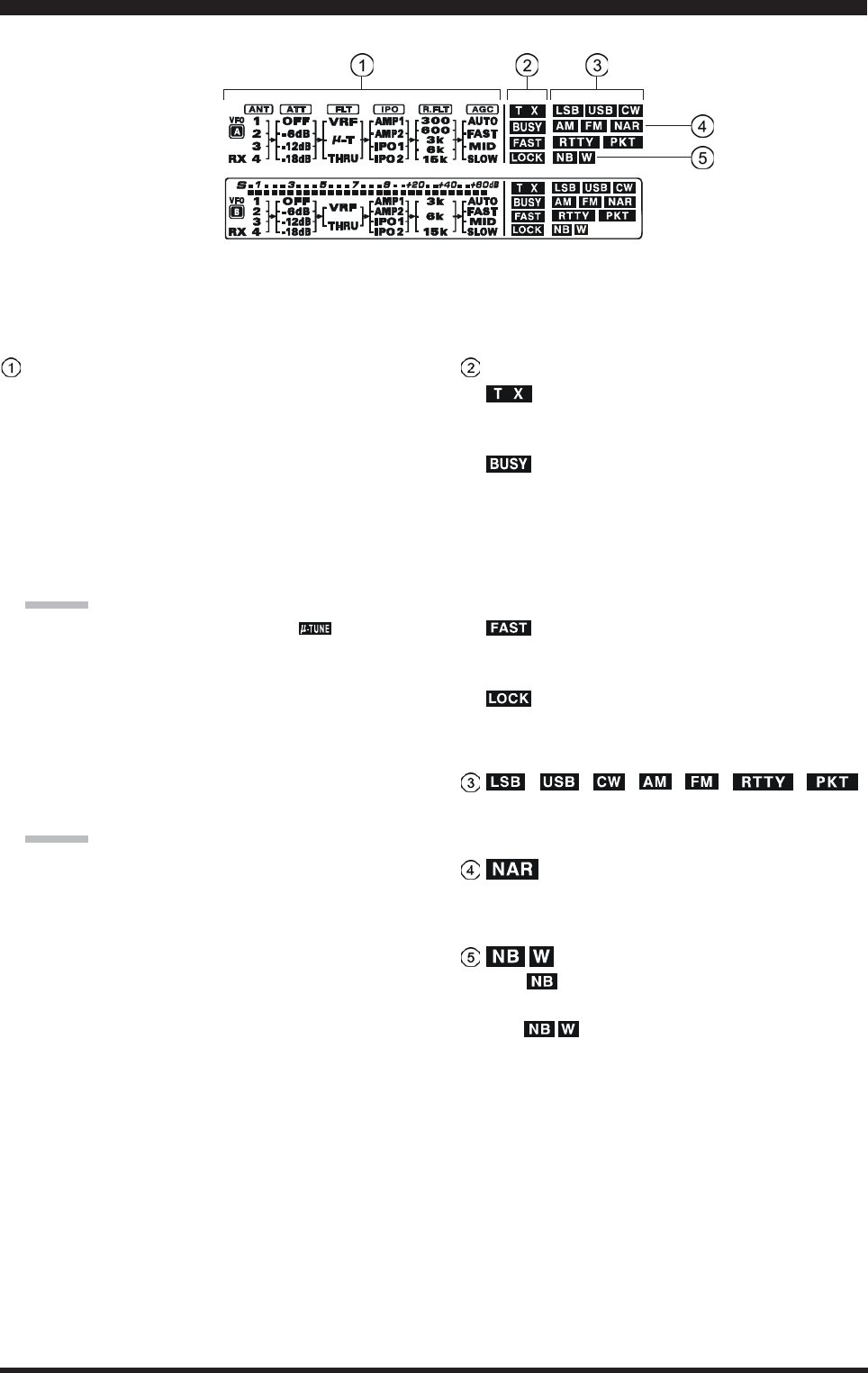
(VFO-A) Block Diagram Display
ANT (1, 2, 3, 4, RX):
Indicates the antenna selected for operation by the front
panel [ANT 1-4] and [RX ANT] switches.
ATT (OFF, –6 dB, –12 dB, –18 dB):
Indicates the attenuation level selected for operation
by the front panel [ATT] button.
FLT (VRF, -TUNE, THRU):
Indicates the RF filter selected for operation by the
front panel (VFO-A)[VRF/-T] button.
ADVICE:
The -TUNE filter is an option. The “ ” icon will
not appear when the optional -TUNE unit is not con-
nected.
IPO (AMP1, AMP2, IPO1, IPO2):
Indicates the front end RF amplifier selected for op-
eration by the front panel [IPO] button.
R.FLT (300, 600, 3k, 6k, 15k):
Indicates the 1st IF Roofing Filter selected for opera-
tion by the front panel [R.FLT] button.
ADVICE:
The 300 Hz Roofing Filter is an option except the MP
version. The “300” icon will not appear when the op-
tional 300 Hz Roofing Filter is not installed.
AGC (AUTO, FAST, MID, SLOW):
Indicates the AGC decay time selected for operation
by the front panel [AGC] switch.
(VFO-A) Status Indicator
:
This indicator appears during transmission on the VFO-
A frequency.
:
This indicator appears whenever the VFO-A receiver
squelch is open. If this indicator is not showing, and
reception seems to have been lost on the VFO-A re-
ceiver for no apparent reason, check the position of
the (VFO-A)[SQL] knob and rotate it fully counter-
clockwise to restore reception.
:
This indicator appears when the Main Tuning Dial
knob’s tuning rate is selected to fast.
:
This indicator appears when the Main Tuning Dial knob
is locked.
, , , , , ,
Displays the currently-selected operating mode for the
VFO-A.
This indicator appears whenever the VFO-A receiver’s
narrow IF DSP filter is engaged.
The “ ” icon appears when the VFO-A receiver’s
(short duration) Noise Blanker is activated.
The “ ” icon appears when the VFO-A receiver’s
(longer-pulse) Noise Blanker is activated.
DISPLAY INDICATIONS (LEFT SIDE)
Page 31FTDX5000 OPERATING MANUAL
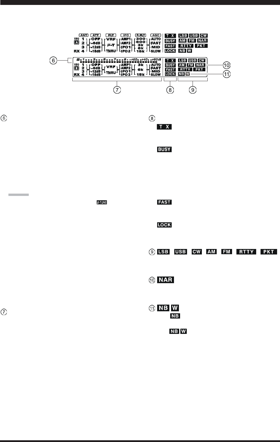
(VFO-B) Block Diagram Display
ANT (1, 2, 3, 4, RX):
Indicates the antenna selected for operation by the front
panel [ANT 1-4] and [RX ANT] switches.
ATT (OFF, –6 dB, –12 dB, –18 dB):
Indicates the attenuation level selected for operation
by the front panel [ATT] button.
FLT (VRF, THRU):
Indicates the RF filter selected for operation by the
front panel (VFO-A)[VRF] button.
ADVICE:
The -TUNE filter is an option. The “ ” icon will
not appear when the optional -TUNE unit is not con-
nected.
IPO (AMP1, AMP2, IPO1, IPO2):
Indicates the front end RF amplifier selected for op-
eration by the front panel [IPO] button.
R.FLT (3k, 6k, 15k):
Indicates the 1st IF Roofing Filter selected for opera-
tion by the front panel [R.FLT] button.
AGC (AUTO, FAST, MID, SLOW):
Indicates the AGC decay time selected for operation
by the front panel [AGC] switch.
This indicator appears whenever the Digital Noise Re-
duction feature is activated.
(VFO-B) Receiver S-Meter
Displays the strength of signals received on the VFO-
B.
(VFO-B) Status Indicator
:
This indicator appears during transmission on the VFO-
B frequency.
:
This indicator appears whenever the VFO-B receiver
squelch is open. If this indicator is not showing, and
reception seems to have been lost on the VFO-B re-
ceiver for no apparent reason, check the position of
the (VFO-B)[SQL] knob and rotate it fully counter-
clockwise to restore reception.
:
This indicator appears when the [CLAR(VFO-B)]
knob’s tuning rate is selected to fast.
:
This indicator appears when the [CLAR(VFO-B)]
knob is locked.
, , , , , ,
Displays the currently-selected operating mode for the
VFO-B.
This indicator appears whenever the VFO-B receiver’s
narrow IF DSP filter is engaged.
The “ ” icon appears when the VFO-B receiver’s
(short duration) Noise Blanker is activated.
The “ ” icon appears when the VFO-B receiver’s
(longer-pulse) Noise Blanker is activated.
DISPLAY INDICATIONS (LEFT SIDE)
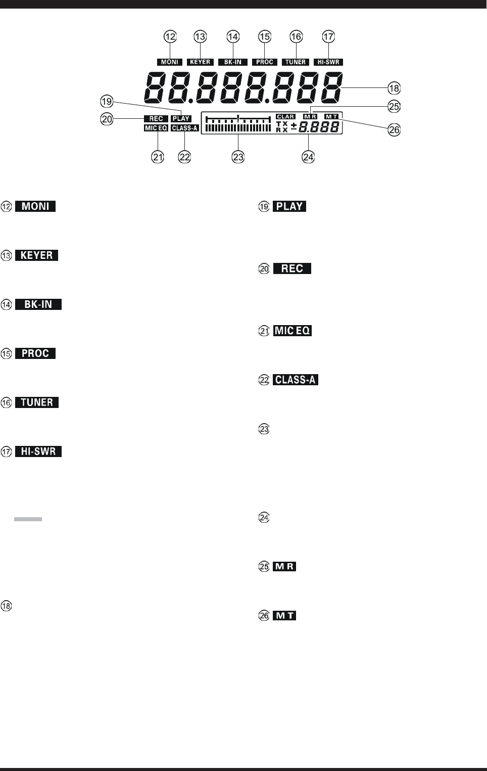
Page 32 FTDX5000 OPERATING MANUAL
This indicator appears whenever the transmit monitor
circuit is activated.
This indicator appears whenever the internal CW keyer
is activated.
This indicator appears whenever CW break-in opera-
tion is activated.
This indicator appears whenever the DSP Speech Pro-
cessor is activated.
This indicator appears when the internal Automatic An-
tenna Tuner is activated.
This indicator appears if the directional coupler and
microprocessor detect an abnormally high SWR con-
dition (over 3.0:1) that cannot be resolved by the Au-
tomatic Antenna Tuner.
NOTE:
If this indicator appears, check to be sure that you have
the correct antenna selected on the current operating
band. If so, you will need to check the condition of the
antenna, its coaxial cable, and/or the connectors on the
cable so as to locate and correct the fault.
VFO-A Frequency Display
This is the VFO-A frequency display.
This indicator appears while the voice recorder is play-
ing back the recorded audio, and/or the memory is play-
ing back the recorded CW or voice message.
This indicator appears while the voice recorder is re-
cording the receiver audio, and/or the memory is re-
cording your CW or voice message.
This indicator appears whenever the Three-Band Para-
metric Microphone Equalizer is activated via the Menu.
This indicator appears when Class-A operation is en-
gaged.
Tuning Offset Indicator
This is a tuning scale that, as configured from the fac-
tory, provides a visual CW tuning indication of the in-
coming signal’s offset from your transceiver’s CW car-
rier frequency, as programmed by the relative clarifier
offset, or the peak position of the VRF/-TUNE filter.
CLAR
This indicator appears whenever the Clarifier function
is activated.
This indicator appears when the transceiver is in the
Memory Recall mode.
This indicator appears when the transceiver is in the
Memory Tune mode to indicate that the memory con-
tents have been temporarily changed.
DISPLAY INDICATIONS (RIGHT SIDE)
Page 33FTDX5000 OPERATING MANUAL
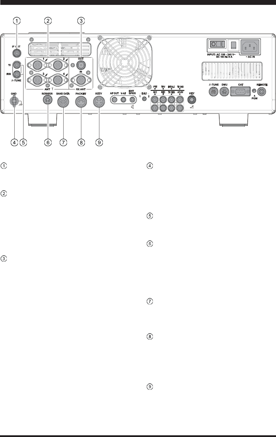
REAR PANEL CONNECTIONS
IF OUT Jacks
This RCA output jack is used for connection to the
optional SM-5000 Station Monitor.
ANT 1, 2, 3, 4 Jacks
Connect your main antenna(s) here, using a type-M
(PL-259) plug and coaxial feedline for each. These an-
tenna ports are always used for transmission, and also
are used for reception unless a separate receive an-
tenna is also used for the receiver. The internal antenna
tuner affects only the antenna(s) connected here, and
only during transmission.
RX ANT IN Jack
The BNC jack provides output of the receiver signal
lines from the Antenna jacks which are connected to
“RX” side of the transceiver’s main T/R switching cir-
cuitry.
The type-M jack is for a separate receive-only antenna.
An antenna connected here can be used when the [RX
ANT] button on the front panel is pressed.
If you want to use some special kind of external
bandpass filter or preamplifier, you may connect it
between the “RX ANT OUT” and “RX ANT IN” jacks.
GND
Use this terminal to connect the transceiver to a good
earth ground, for safety and optimum performance. Use
a large diameter, short braided cable for making ground
connections, and please refer to page 9 for other notes
about proper grounding.
-TUNE Jacks
These jacks are used for signal input/output of the op-
tional RF Tuning Kit.
ROTATOR Jack
This 6-pin MINI-DIN Jack accepts a cable connected
to a YAESU G-800DXA/-1000DXA/-2800DXA An-
tenna Rotator (listed models are current as of early
2010). You may control the antenna azimuth rotation
(and rotation speed) using the Function buttons on the
front panel.
BAND DATA Jack
This 8-pin output jack provides band selection data
which may be used for control of optional accessories
such as the VL-1000 Solid-state Linear Amplifier.
PACKET Jack
This 5-pin input/output jack provides receiver audio
and squelch signals, and accepts transmit (AFSK) au-
dio and PTT control, from an external Packet TNC.
Pinout is shown on page 15. The receiver audio level
at this jack is approximately 100 mVp-p (@600 Ohms).
RTTY Jack
This 4-pin input/output jack provides connections for
an RTTY terminal unit. Pinout is shown on page 15.
The receiver audio level at this jack is at a constant
100-mV (@600 Ohms) level. FSK keying at this jack
is accomplished by a closure of the SHIFT line to
ground by the terminal unit.
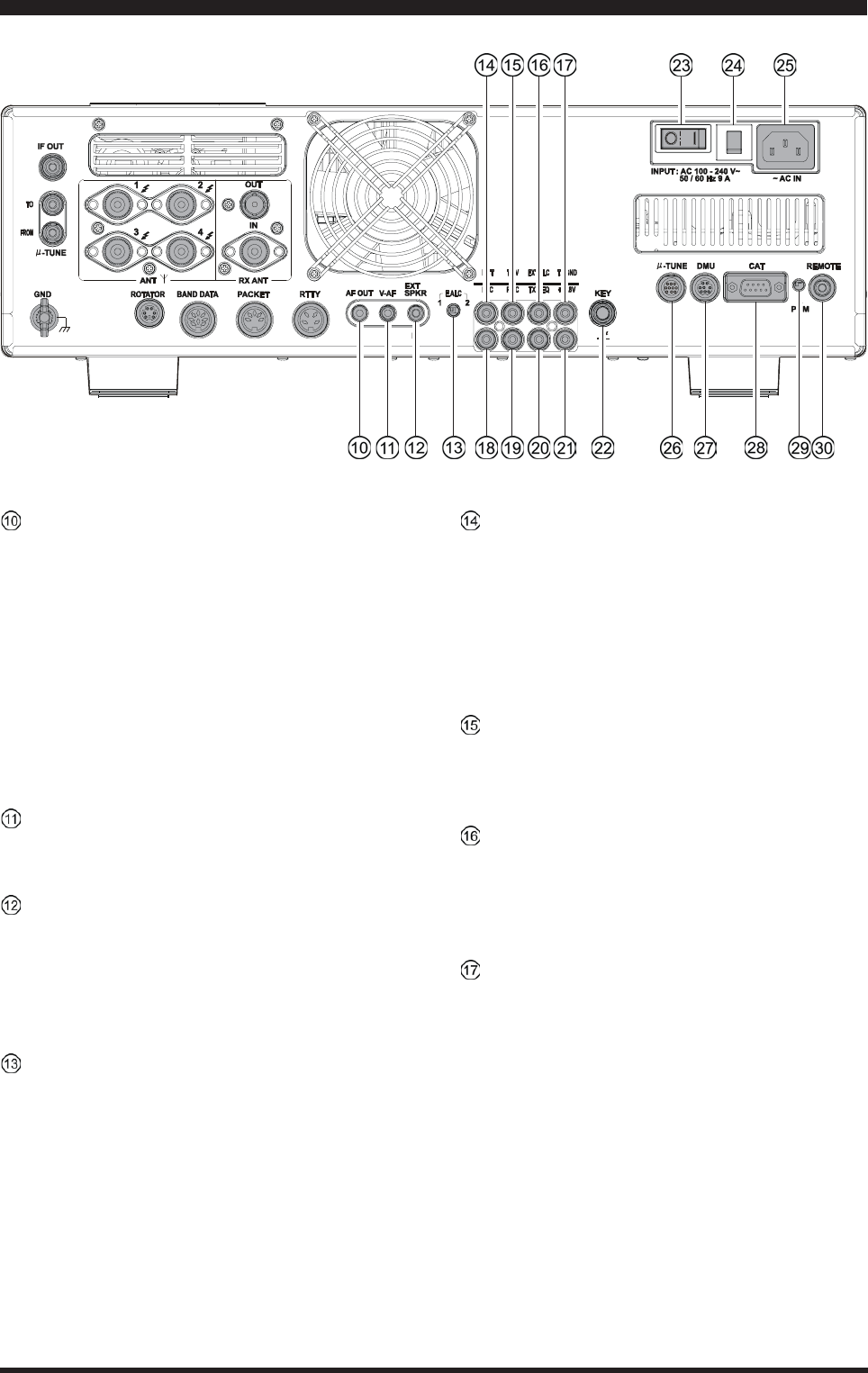
Page 34 FTDX5000 OPERATING MANUAL
AF OUT Jack
This 3.5-mm, 3-contact jack provides dual-channel
low-level receiver output, for recording or external am-
plification. Peak signal level is 300 mVp-p at 10 k-
Ohms. TheVFO-A receiver audio is on the left chan-
nel (tip), and the VFO-B receiver audio is on the right
channel (ring). A stereo amplifier or recorder is rec-
ommended, to record each receiver’s audio separately
when dual reception is enabled (audio from either re-
ceiver, or both, may be used via this jack). The front
panel [AF GAIN] knobs do not affect the signals at
this jack.
V-AF Jack
This 3.5-mm, 3-contact jack is used for connection to
the optional SM-5000 Station Monitor.
EXT SPKR Jack
This 3.5-mm, 2-contact jack provides receiving audio
output from the VFO-A and VFO-B receivers for an
external loudspeaker or speakers, such as the SP-2000.
Inserting a plug into this jack disables the internal loud-
speaker. Impedance is 4 ~ 8 Ohms.
E.ALC Switch
This slide switch is used for selecting the recovery time
of the ALC.. Set this switch to “1” position when this
transceiver connects to the optional VL-1000 Solid-
state Linear Amplifier.
PTTJack
This RCA input jack may be used to provide manual
transmitter activation using a footswitch or other
switching device. Its function is identical to the [MOX]
button on the front panel. The same line is available at
the PACKET and RTTY jacks for TNC control. Open-
circuit voltage is +13.5 VDC, and closed-circuit cur-
rent is 5 mA.
TRV Jack
This RCA jack provides a low level RF output for use
with a transverter. Maximum output is approximately
–10 dBm (0.1 mW) at 50 Ohms.
EXT ALC Jack
This RCA input jack accepts negative-going external
ALC (Automatic Level Control) voltage from a linear
amplifier, to prevent over-excitation by the transceiver.
Acceptable input voltage range is 0 to –4 VDC.
TX GND Jack
This RCA jack’s center pin is closed to ground while
the transceiver’s transmitter is engaged. It may be used
for control of a peripheral device, most typically a lin-
ear amplifier. To enable this jack, please set Menu item
“146 tGEn ETX-GND” to the “EnA” (Enable) selec-
tion.
The relay circuit of this transceiver used for this jack
is capable of switching AC voltage of 100 Volts at up
to 300 mA, or DC voltages or 60 V at 200 mA or 30 V
at up to 1 Amp.
REAR PANEL CONNECTIONS
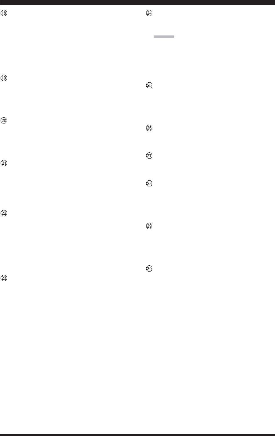
Page 35FTDX5000 OPERATING MANUAL
REAR PANEL CONNECTIONS
MIC (PATCH) Jack
This RCA input jack accepts transmitter audio - either
AFSK or voice - for transmission. This line is mixed
with the microphone audio input line, so the micro-
phone should be disconnected if using this jack and
mixing is not desired. The optimum impedance is 500
~ 600 Ohms, and the nominal input level should be 5
mV.
REC Jack
This RCA jack provides low-level receiver audio out-
put and transmit (monitor) audio (requires the [MONI]
button is turned on), for recording or external amplifi-
cation. Peak signal level is 30 mVp-p at 10 k-Ohms.
TX REQ Jack
When this RCA jack shorted to ground, it puts the trans-
ceiver into the transmit mode, and sends out a steady
CW carrier, for linear amplifier or manual antenna tuner
adjustment.
+13.8 V Jack
This RCA output jack provides regulated, separately
fused 13.8 VDC at up to 200 mA, to power an external
device such as a packet TNC. Make sure your device
does not require more current (if it does, use a separate
power source).
KEY Jack
This 1/4-inch phone jack accepts a CW key or keyer
paddle. A 2-contact plug cannot be used in this jack.
Key-up voltage is +5 V, and key-down current is 1 mA.
Plug wiring is shown on page 15, and this jack may be
configured for keyer, “Bug,” “straight key,” or com-
puter keying interface operation via Menu item “056
A1A R-TYPE.”
Main Power Switch
This is main power “on” (I)/“off” (O) switch of the
transceiver. Always turn this switch on before turning
on the front panel’s [POWER] button.
If this switch is not turned “on”, the front panel
[POWER] switch will not function.
Circuit Breaker Switch
This circuit breaker shuts off in the event of danger-
ously high current consumption by the transceiver.
ADVICE:
If the Circuit Breaker interrupts power, by all means
try to determine the cause of the over-current condi-
tion before re-applying power. To restore the Circuit
Breaker after verifying that all is normal, push this
switch in until you hear a “click.”
~AC IN Jack
Connect the supplied 3-wire AC line cord to this socket.
AC voltages of 100-240 V may be accommodated by
the transceiver any sort of modification (universal volt-
age input).
-TUNE Jack
This 10-pin MINI-DIN jack used for control of the
optional RF Tuning Kit.
DMU Jack
This 8-pin MINI-DIN jack accepts a cable connected
to an optional DMU-2000 Data Management Unit.
CAT Jack
This 9-pin serial DB-9 jack allows external computer
control of the transceiver. Connect a serial cable here
and to the RS-232C COM port on your personal com-
puter (no external interface is required).
PGM (PROGRAM) Switch
This slide switch is used for updating the transceiver’s
firmware. The update software and instructions are
available for download from the Vertex Standard
website (http://www.yaesu.com/).
REMOTE Jack
By plugging in the supplied FH-2 Remote Control Key-
pad to this jack, direct access to the CPU of the trans-
ceiver is provided for control functions such as audio
playback feature, contest memory keying, plus fre-
quency and function control.
Page 36 FTDX5000 OPERATING MANUAL
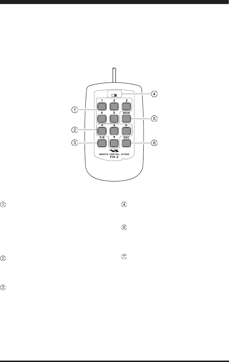
FH-2 SWITCHES
The supplied Remote Control Keypad “FH-2” can be used to control the voice memory capability for the SSB/AM/FM
modes, and the contest memory keyer for the CW mode. You can also play-back up to 15 seconds of incoming received
audio, as well, for verification of a missed callsign or other purposes. Among the specific capabilities of the FH-2 are:
On SSB/AM/FM modes, five channels of storage and playback of voice memory (20 seconds each), using your own
voice for recording (see page ???).
On CW mode, the FH-2 provides storage and recall of CW messages for repetitive CQ and contest number transmis-
sions (see page ???).
Play-back of the last 15 seconds of incoming receiver audio (see page ???).
[1], [2], [3], [4], [5] Switches
These buttons work as the Voice Memory and CW Mes-
sage Memory Selection Key.
In the case of Voice Memory, up to 20 seconds of au-
dio may be stored on each channel.
For CW Messages and CW Text Messages, up to 50
characters (“PARIS” specification) may be stored into
each channel.
[W], [X], [S], [T] Switches
These buttons are used for navigation when selecting
text characters for the programming of Contest and Text
memories.
[P/B] Switch
This button is used for playing back the last 15 sec-
onds of recorded receiver audio.
LOCK
OFFON
[LOCK] Switch
This button may be used to lock out the FH-2’s keys,
to prevent accidental activation of FH-2 operation.
[MEM] Switch
This button is pressed for the purpose of storing either
a Voice Memory or a Contest Keyer Memory channel’s
contents.
[DEC] Switch
When utilizing the sequential contest number capabil-
ity of the Contest Keyer, press this button to decre-
ment (back up) the current Contest Number by one digit
(i.e. to back up from #198 to #197, etc.).

Page 37FTDX5000 OPERATING MANUAL
Before turning on main power, please verify the following items once more.
Have you made all ground connections securely? See page 9 for details.
Do you have your antenna(s) connected to the rear-panel Antenna jack(s)? See page ?? for details.
Is your microphone (and/or key or paddle) connected? See pages ?? and ?? for details.
If using a linear amplifier, have all interconnections been successfully completed? See pages ?? and ?? for details.
Please rotate both [AF GAIN] controls to their fully counter-clockwise positions, to avoid a loud blast of audio when
the transceiver turns on. See page ?? for details.
Rotate the [RF PWR] control fully counter-clockwise, to set minimum power at first. See page ?? for details.
If your AC mains power should suffer a significant fluctuation or interruption, we recommend that you go through a
complete power-up cycle, in order to ensure that all circuits are properly initialized. To do this, be sure the front panel
[POWER] switch is turned off, then set the rear panel main power switch to the “O” position. Now unplug the AC
cable from the rear panel, and wait ten seconds before proceeding with the start-up procedure described on next page.
BASIC OPERATION:RECEIVING ON AMATEUR BANDS
35
16 34
33 34
20
20
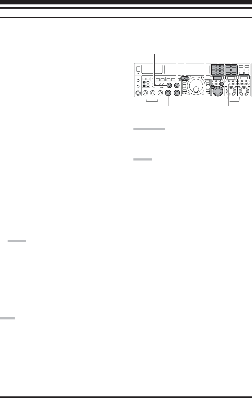
Page 38 FTDX5000 OPERATING MANUAL
Main Tuning Dial knob
[ANTENNA] Buttons [BAND] Buttons
(VFO-B)[SQL] Knob
[BAND/MHz] Button
[FAST] Button
[CLAR(VFO-B)] Knob
1. Plug the AC cable back in, set the rear
panel main power switch to “I” posi-
tion.
2. Press and hold in the front panel
[POWER] switch for one second to turn
the transceiver on.
3. The transceiver will start up on 7.000.00
MHz LSB, and normal operation may begin.
NOTE:
To turn power off, press and hold in the front panel
[POWER] switch for one second.
4. Rotate the (VFO-A)[AF GAIN]
knob to set a comfortable audio level
on incoming signals or noise. Clock-
wise rotation of the (VFO-A)[AF
GAIN] knob increases the volume
level.
NOTE:
When using headphones, start by rotating the (VFO-
A)[AF GAIN] knob counter-clockwise, then bring the
volume level up after you put the headphones on. This
will minimize the chance of damage to your hearing
caused by an unexpectedly-high audio level.
5. Press the (VFO-A)[RX]
button to engage the VFO-
A receiver; the imbedded
LED will glow green.
ADVICE::
::
:
If you press the (VFO-
A)[RX] button when the imbedded LED is already
glowing green, the LED will now blinks; this indi-
cates that the VFO-A receiver is temporarily muted.
Just press the (VFO-A) [RX] button once more to
restore VFO-A receiver operation.
Press the (VFO-B)[RX] button to
engage Dual Reception (using the
VFO-B receiver in addition to the
VFO-A receiver). When you press
the (VFO-B)[RX] button, its imbed-
ded LED will glow green; press-
ing this button once more will
turn off the VFO-B receiver, and
the imbeded LED will go dark.
Use the VFO-B receiver’s (VFO-
B)[AF GAIN] knob to adjust the
VFO-B receiver volume level.
6. Press the [BAND] button
corresponding to the Ama-
teur band on which you wish
to begin operation.
ADVICE::
::
:
One-touch selection of
each Amateur band be-
tween 1.8 and 50 MHz is provided.
The FTDX5000 utilizes a triple band-stack VFO
selection technique, which permits you to store up
to three favorite frequencies and modes onto each
band’s VFO register. For example, you may store
one frequency each on 14 MHz CW, RTTY, and
USB, then recall these VFOs by successive, mo-
mentary presses of the [14] MHz band button. Each
Amateur band button may similarly have up to three
frequency/mode settings applied.
[POWER] Switch
(VFO-A)[RX] Button
BASIC OPERATION:RECEIVING ON AMATEUR BANDS
Here is the typical start-up procedure for normal operation:
(VFO-A)[SQL] Knob [MODE] Buttons
(VFO-B)[AF GAIN] Knob
(VFO-A)[AF GAIN] Knob
[(T)DOWN] /[(S)UP] Buttons
(VFO-B)[RX] Button
Page 39FTDX5000 OPERATING MANUAL
If you press the
[BAND/MCH] but-
ton briefly, the im-
bedded LED of the
[BAND/MCH] but-
ton glows red, and the
[CLAR(VFO-B)]
knob may be used as
a band selection
knob.
7. Press the [T(DOWN)]/[S(UP)] buttons to tune the
VFO-A frequency in 1 MHz
step.
ADVICE::
::
:
You may change the tuning step to 100 kHz via the
Menu item “140 TUN MHz SEL”. See page 127.
8. Move the [ANT 1-4] button up and down to select the
appropriate antenna for the band in use; alternatively,
if one is connected, you may also press the [RX ANT]
button. Up to four TX/RX anten-
nas may be connected, or one RX-
only antenna.
ADVICE::
::
:
Once you have made your antenna selection, that an-
tenna is “remembered” by the microprocessor in con-
junction with the VFO register (frequency and mode)
in use when you chose that particular antenna.
9. Press the appropriate [MODE]
button to select the desired op-
erating mode.
ADVICE::
::
:
By convention in the Ama-
teur bands, LSB is used on
the 7 MHz and lower bands
(with the exception of 60 meters), while USB is
utilized on the 14 MHz and higher bands.
When changing modes from SSB to CW, you will
observe a frequency shift on the display. This shift
represents the BFO offset between the “zero beat”
frequency and the audible CW pitch (tone) you can
hear (the pitch is programmed by the [PITCH]
knob), even though the actual tone that you hear is
not changing. If you do not want this frequency shift
to appear when changing modes from (for example)
USB to CW, use the Menu item “063 A1A
FRQDISP,” described on page 122.
When operating on the FM mode
in the VFO-A, rotate the (VFO-
A)[SQL] (Squelch) knob clock-
wise just to the point where the
background noise is just silenced.
This is the point of maximum sensitivity to weak
signals. Excessive advancement of
the Squelch knob will degrade the
ability of the receiver to detect
weak signals. Adjustment of the
VFO-B Squelch is accomplished
using the (VFO-B)[SQL] knob.
10.
Rotate the Main Tuning Dial knob to tune around the
band, and begin normal operation.
ADVICE::
::
:
Clockwise rotation of the Main Tuning Dial knob
increases the operating frequency, one “step” of the
synthesizer at a time; similarly, counter-clockwise
rotation of the Main Tuning Dial knob will decrease
the frequency.
Two steps, one “normal”
and one “fast,” are avail-
able on each operating
mode. Pressing the
[FAST] button engages
the “Fast” tuning selec-
tion.
BASIC OPERATION:RECEIVING ON AMATEUR BANDS
OPERATING MODE 1 STEP 1 DIAL ROTATION
LSB, USB, CW, 10Hz 10kHz
RTTY, PKT(LSB)[
100Hz][
100kHz]
AM, FM, PKT(FM)100Hz [1kHz]100kHz [1MHz]
[ ] : [FAST] switch set to “ON”
It is possible to separate the frequency change over
one dial rotation, only while operating solely on
the CW mode, using the Menu items “138 TUN
DIAL STP”, and “139 TUN CW FINE”. See page
127.
If you want to navigate quickly, so as to effect rapid
frequency change, there are several techniques
available:
yDirect keyboard entry of the frequency (see page
49).
yUse the microphone’s [UP]/[DWN] scanning
keys, if your microphone is so equipped (see
page 49).
Page 40 FTDX5000 OPERATING MANUAL
BASIC OPERATION:RECEIVING ON AMATEUR BANDS
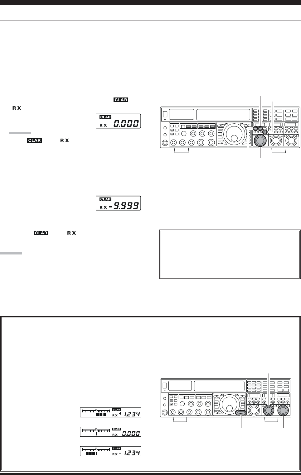
CLAR (CLARIFIER) OPERATION ON VFO-A
The [RX CLAR/FAST], [CLEAR], [TX CLAR/LOCK] buttons and [CLAR(VFO-B)] knob are used to offset either the
receive, transmit, or both frequencies from their settings on the VFO-A frequency (the Clarifier does not affect the VFO-B,
however). The four small numbers on the LCD display show the current Clarifier offset. The Clarifier controls on the
FTDX5000 are designed to allow you to preset an offset (up to ±9.999 kHz; frequency step depends on the Main Tuning
Dial knob) without actually retuning, and then to activate it via the Clarifier’s [RX CLAR/FAST] and [TX CLAR/LOCK]
buttons. This feature is ideal for following a drifting station, or for setting small frequency offsets sometimes utilized in DX
“Split” work.
Here is the technique for utilizing the Clarifier:
1. Press the [RX CLAR/FAST] button. The “ ” and
“” icon will appear in the display, and the pro-
grammed offset will be applied to
the receive frequency.
ADVICE::
::
:
If the “ ” and “ ” icon does not appear, check
to see if the LED imbedded in the [A/B] button glows
orange. If so, pressing the [A/B] button will cause the
LED imbedded in the [A/B] button to go out. Now,
press the [RX CLAR/FAST] button to begin clarifier
operation.
2. Rotation of the [CLAR(VFO-B)] knob will allow you
to modify your initial offset on the
fly. Offsets of up to ±9.999 kHz
may be set using the Clarifier.
To cancel Clarifier operation, press the [RX CLAR/FAST]
button. The “ ” and “ ” icon will disappear from
the display.
ADVICE:
Turning the clarifier “off” simply cancels the application
of the programmed offset from the receive and/or transmit
frequencies. To clear out the programmed clarifier offset
altogether, and reset it to “zero,” press the [CLEAR] but-
ton.
TX CLAR
Without changing the receive frequency, you may
alternatively apply the Clarifier offset to the trans-
mit frequency (typically, for “split” DX pile-ups).
See page 79 for details.
The Tuning Offset Indicator provides a graphical representation of the Clarifier offset.
On CW mode, the Tuning Offset Indicator is used for CW Center Tuning, instead of Clarifier Offset, as the trans-
ceiver is configured at the factory. If you wish to change this, so that the Clarifier Offset is also displayed on CW, use
the following procedure:
1. Press the [MENU] button to enter the Menu mode.
2. Rotate the (VFO-A)[SELECT] knob to select
Menu item “010 DISP BAR SEL”.
3. Rotate the (VFO-B)[SELECT] knob to select
“CLARCLAR
CLARCLAR
CLAR (Clarifier)” (replacing the default “CWCW
CWCW
CW
TUNETUNE
TUNETUNE
TUNE (CW TUNING)”
selection).
4. Press and hold in the
[MENU] button for two
seconds to save the new
setting and exit to nor-
mal operation.
[CLAR(VFO-B)] Knob
[RX CLAR/FAST] Button
[CLEAR] Button
[A/B] Button
[Plus (+) Offset]
[Zero Offset]
(Minus (–) Offset)
(VFO-B)[SELECT] Knob
[MENU] Button
(VFO-A)[SELECT] Knob
Page 41FTDX5000 OPERATING MANUAL
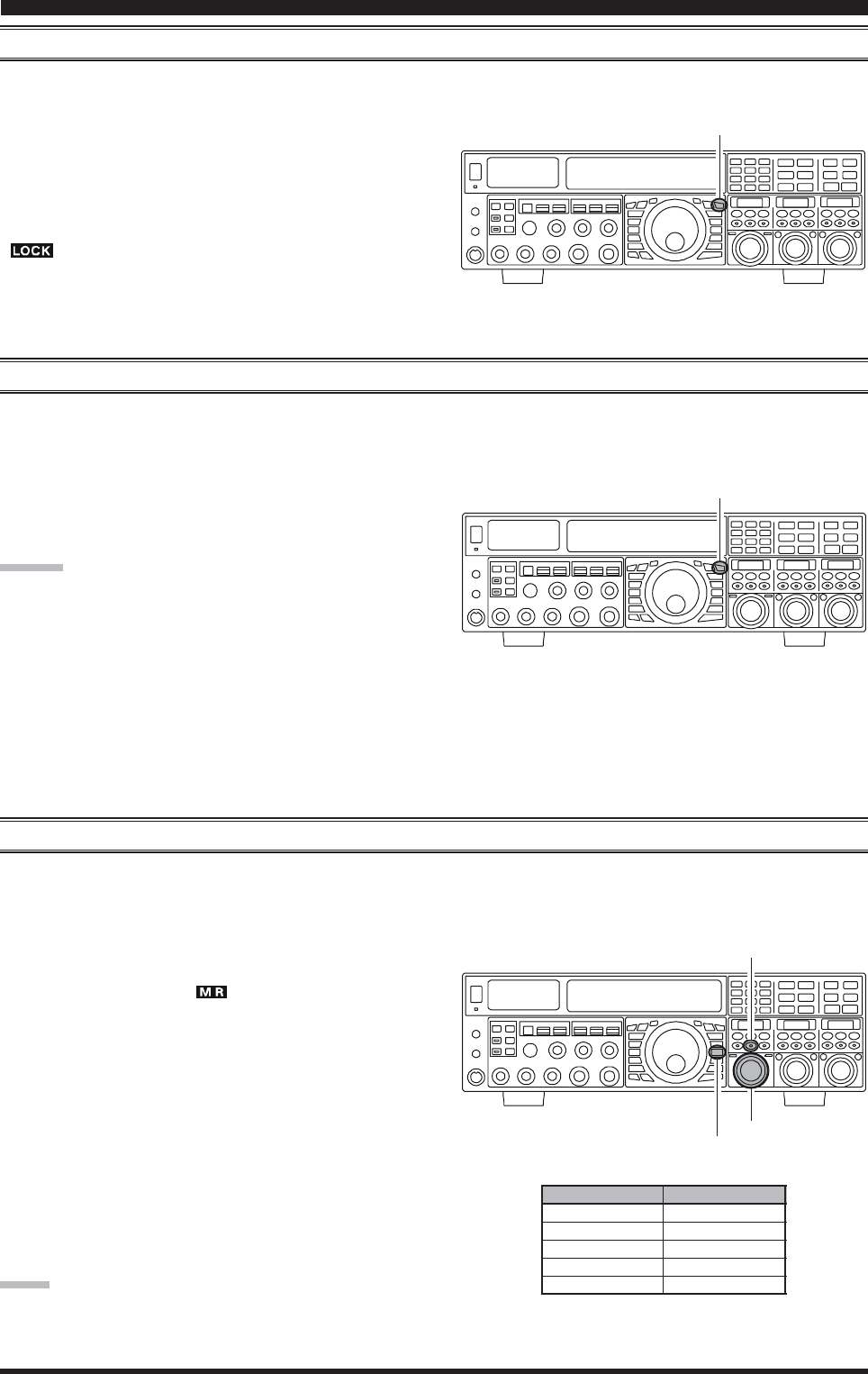
LOCK
You may lock the setting of the Main Tuning Dial knob, to prevent accidental frequency change.
To lock out the Main Tuning Dial knob, just press the
[LOCK] button that is located to the right of the Main
Tuning Dial knob. To unlock the Dial setting, and restore
normal tuning, just press the [LOCK] button once more.
When the Main Tuning Dial knob is “locked”, the blue
“” icon will appear on the display.
DIM
The illumination level of the analog meter and frequency display may be reduced, if you are using the transceiver in a dark
environment where high brightness is not desired.
To reduce the illumination level, press the [DIM] button,
located to the left of the analog meter. To restore full bright-
ness, press the [DIM] button once more.
ADVICE:
You may also customize the amount of brightness reduc-
tion engaged by the pressing of the [DIM] button, and may
use different brightness levels for different front panel ar-
eas. Menu item “008 DISP DIM MTR” adjusts the bright-
ness level of the analog meter; while menu item “009 DISP
DIM VFD” sets the brightness levels of the frequency dis-
play (these settings are effective only when the [DIM] but-
ton is pressed).
[LOCK] Button
[LOCK] Button
OPERATION ON 60-METER (5 MHZ) BAND (U.S. VERSION ONLY)
The recently-released 60-meter band is covered, in the FTDX5000, by five special, fixed memory channels. These channels are
set to USB, and they appear between the “last” PMS channel (“P-9UP-9U
P-9UP-9U
P-9U”) and the first “regular” memory channel (Channel 1).
To operate on the 60-meter (5 MHz) band:
1. Press the [V/M] button once, if neccessary, to enter the
“Memory” mode (the “ ” icon will appear on the
display.
2. Press and hold in the [BAND/MCH] button for two
seconds. The LED imbedded in the button will glow
yellow to signify that rotation of the [CLAR(VFO-B)]
knob will allow selection the memory channel.
3. Memory channels “US-1US-1
US-1US-1
US-1” through “US-5US-5
US-5US-5
US-5” are pre-pro-
grammed, at the factory, with the permitted frequen-
cies in the 5 MHz band, and the USB mode is auto-
matically selected on these channels.
4. To exit from 60-meter operation and return to the VFO
mode, just press the [V/M] button.
NOTE:
The frequencies and operating mode for 5 MHz band op-
eration are both fixed, and may not be changed.
[CLAR(VFO-B)] Knob
[V/M] Button
[BAND/MCH] Button
CHANNEL NUMBER
US-1
US-2
US-3
US-4
US-5
FREQUENCY
5.3320 MHz
5,3480 MHz
5.3680 MHz
5.3730 MHz
5.4050 MHz
BASIC OPERATION:RECEIVING ON AMATEUR BANDS
Page 42 FTDX5000 OPERATING MANUAL
QUICK POINT:
By convention in the amateur bands, LSB is used on the 7
MHz and lower bands (with the exception of 60 meters),
while USB is utilized on the 14 MHz and higher bands.
ADVICE:
When operating in Dual Receive, the manner in which
the audio is fed to the left and right sides of your head-
phones (Stereo, Monaural, or Mixed) may be config-
ured using Menu item “104 ROUT HEADPHN” (see
page 124).
When changing modes from SSB to CW, you will ob-
serve a frequency shift on the display. This shift repre-
sents the BFO offset between the “zero beat” frequency
and the audible CW pitch (tone) you can hear (the pitch
is programmed by the [PITCH] knob), even though
the actual tone that you hear is not changing. If you do
not want this frequency shift to appear when changing
modes from (for example) USB to CW, use the Menu
item “062 A1A FRQ DISP”, described on page 122.
When operating on the FM mode on the VFO-B re-
ceiver, rotate the (VFO-B)[SQL] knob clockwise just
to the point where the background noise is just silenced.
This is the point of maximum sensitivity to weak sig-
nals. Excessive advancement of the (VFO-B)[SQL]
knob will degrade the ability of the receiver to detect
weak signals. Adjustment of the VFO-A squelch is ac-
complished using the (VFO-A)[SQL] knob.
DUAL RECEIVE
The FTDX5000 is capable of simultaneous reception on the same amateur band, using the VFO-A and VFO-B receivers,
in what is called the “Dual Receive” mode. Especially useful for DX work, here is the operating procedure for Dual Receive
operation.
CONVENIENCE FEATURES
1. While receiving on the VFO-A, engage the VFO-B
receiver by pressing the (VFO-B)[RX] button, located
to the upper left of the [CLAR(VFO-B)] knob. You
will now be receiving on the two frequencies shown
on the LCD display (for VFO-A) and SUB DISPLAY-
I
(for VFO-B).
2. Adjusting the volume:
To adjust the VFO-A audio level, rotate the (VFO-
A)[AF GAIN] knob. To adjust the VFO-B audio level,
rotate the (VFO-B)[AF GAIN] knob. In both cases,
clockwise rotation of the knob will increase the vol-
ume level.
3. Press the [B] button, located to the upper left of the
Main Tuning Dial knob. An orange LED imbedded in
the [B] button, and you may now change the operating
mode of the VFO-B receiver by pressing the appropri-
ate [MODE] selection button.
4. You may also press the [BAND] buttons to select the
operating band on which you want to set up the VFO-
B receiver.
5. To return the mode and band selections to VFO-A, press
the [A] button, located to the left of the [B] button. A
red LED imbedded in the [A] button, and you may now
change the operating mode and band of the VFO-A
receiver.
6. Rotate the Main Tuning Dial knob to adjust the Main
VFO-A frequency, and rotate the [CLAR(VFO-B)]
knob to adjust the VFO-B frequency.
ADVICE::
::
:
If the VFO-B frequency does not change, check to see
if the orange LED imbedded in the [A/B] button does
not light up. If so, pressing the [A/B] button will cause
the LED imbedded in the [A/B] button glows orange.
Now, rotate the [CLAR(VFO-B)] knob to begin to
adjust the VFO-B frequency.
7. To cancel Dual Receive operation, and receive just on
the VFO-A receiver, press the (VFO-B)[RX] button;
the imbedded green LED will go out, and monoband
operation on the VFO-A receiver will resume.
NOTE::
::
:
Please remember that, while the [B] button glows orange,
any mode or band changes will still be applied to the VFO-
B receiver, whether or not Dual Receive is engaged.
[CLAR(VFO-B)] Knob
[A/B] Button
[BAND] Buttons
[MODE] Buttons
SUB DISPLAY-I
(VFO-B)[RX] Button
[A] / [B] Buttons
(VFO-A)[SQL] Knob
(VFO-B)[SQL] Knob
(VFO-A)[AF GAIN] Knob
(VFO-B)[AF GAIN] Knob

Page 43FTDX5000 OPERATING MANUAL
CONVENIENCE FEATURES
DUAL RECEIVE
Using Headphones for Dual Receive
To take advantage of dual reception, you will want to con-
nect stereo headphones to the PHONES jack. Like the
AF GAIN control, headphone audio mixing can also be
configured as desired from Menu item “104 ROUT
HEADPHN”. Three audio mixing schemes are selectable
as follows:
SEPARETESEPARETE
SEPARETESEPARETE
SEPARETE: Audio from the VFO-A receiver is heard only
in the left ear, and VFO-B receiver audio
solely in the right ear.
CONBINE1CONBINE1
CONBINE1CONBINE1
CONBINE1: Audio from both VFO-A and VFO-B receiv-
ers can be heard in both ears, but VFO-B
audio is attenuated in the left ear and VFO-
A audio is attenuated in the right ear.
CONBINE2CONBINE2
CONBINE2CONBINE2
CONBINE2: Audio from both VFO-A and VFO-B receiv-
ers are combined and heard equally in both
ears (“Monaural” mode).
Sideband Diversity Reception
Here you receive a single AM signal through the two re-
ceivers, each receiving the opposite sideband. Skywave-
propagated signals often show phase distortion in this
mode, but it gives you a view of the entire passband, from
which you can then select the best sideband for listening
(or for SWL Dx’ing, you may want to listen to both side-
bands at the same time, to get the best copy). On
groundwave signals, where the phase of the sidebands is
likely to be the same, there is an interesting sense of depth
to the signal.
To tune in a signal using this mode, you should have ste-
reo headphones connected to the front panel PHONES
jack.
Set the VFO-A to either LSB or USB mode, and tune
for zero beat on the desired signal.
Press the [A
XX
XX
X
B] button to copy this mode and fre-
quency into the VFO-B, then press the [MODE] but-
ton to select the opposite sideband for the VFO-A.
If using headphones, set the headphone mixing scheme
to the “CONBINE1CONBINE1
CONBINE1CONBINE1
CONBINE1” mode via the Menu item “104
ROUT HEADPHN”, and activate dual reception.
Adjust the [AF GAIN] knob(s) to balance the volume
of the two receivers.
If interference is present on one of the channels, you
may have to turn its [AF GAIN] knob to suppress that
channel (or press the green [RX] button to disable the
receiver with the sideband experiencing interference).
Otherwise, try changing the headphone audio mixing
scheme to “CONBINE2CONBINE2
CONBINE2CONBINE2
CONBINE2” or “SEPARETESEPARETE
SEPARETESEPARETE
SEPARETE” in the Menu
item “104 ROUT HEADPHN”, for different effects
(or try settings with similar effects on your external
amplifier). Although you don’t get the “stereophonic”
effect in the monaural mode, the two signals are still
mixed, offering the potential for much better copy than
in regular AM or even single-sideband ECSS modes.

Page 44 FTDX5000 OPERATING MANUAL
Bandwidth Diversity Reception
This mode involves receiving the same signal through two
different bandpass filters. The frequency and mode of both
the VFO-A and VFO-B are the same. The VFO-A can be
set up for a wide bandpass, using the [WIDTH] knobs,
and the VFO-B for a narrow bandpass, resulting in a spa-
tial perception of the channel. Although any mode (except
FM) can be used, CW offers the widest array of choices,
and perhaps the most startling effects on crowded chan-
nels.
Stereo headphones or an external stereo speaker are rec-
ommended for this mode. To set up the transceiver for
bandwidth diversity reception:
Select the desired mode on the VFO-A.
Tune to the signal of interest.
Press the [A
XX
XX
X
B] button to copy this mode and fre-
quency into the VFO-B.
If using headphones, set the headphone mixing scheme
to the “CONBINE1CONBINE1
CONBINE1CONBINE1
CONBINE1” mode via the Menu item “104
ROUT HEADPHN”, and activate dual reception.
Adjust the [AF GAIN] knob(s) to balance the volume
of the two receivers.
Now try manipulating the [SHIFT] and [WIDTH]
knobs to observe the interesting effects of bandwidth
diversity.
CONVENIENCE FEATURES
DUAL RECEIVE
Polarity Diversity
Similar in concept to the bandwidth diversity ca-
pability just described, another interesting capabil-
ity of the FTDX5000 is the ability to use two differ-
ent antennas on the same frequency, using dual re-
ception. For example, you might have a horizontal
Yagi on the main band, and a vertical antenna on
the sub band, then lock the two frequencies together
and engage dual reception.
Frequently, the fading observed on the HF bands is
not so much a change in ionization level, but rather
a shift in the polarization of the signal as it travels
to and from the ionosphere. Having an opposite-
polarization antenna available can fill in the signal
during deep fades, and you may then transmit on
whichever antenna is providing the strongest sig-
nal at the moment (see the discussion below on Split
Frequency operation).
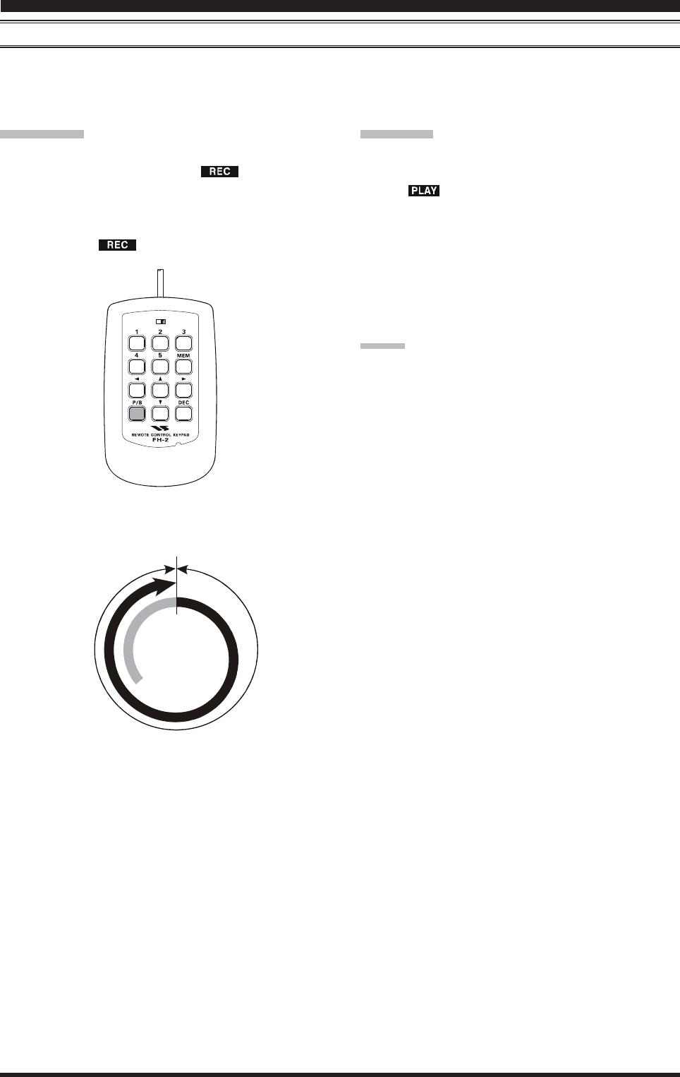
Page 45FTDX5000 OPERATING MANUAL
CONVENIENCE FEATURES
P.BACK (AUDIO PLAYBACK) FROM MAIN (VFO-A) RECEIVER
Once engaged by the operator, the FTDX5000 begins the automatic recording of the last 15 seconds of incoming receiver
audio on the VFO-A by plugging in the supplied FH-2 Remote Control Keypad into the rear panel’s REMOTE jack. This
capability is especially useful for confirming a callsign that may have been difficult to copy due to noise or QRM, etc.
Recording
Press and hold in the FH-2’s [P/B] key for two sec-
onds to initiate recording. The “ ” icon will ap-
pear in the display to confirm that recording is in
progress.
Press the FH-2’s [P/B] key momentarily to halt re-
cording; the “ ” icon will go out.
LOCK
OFFON
Playback
Press the FH-2’s [P/B] key briefly, after recording has
been halted, to begin playback of the recorded audio;
the “ ” icon will appear in the display to confirm
that playback is in progress. The last 15 seconds of
audio will be heard in the speaker or headphones. If
you do not intervene, the entire 15 seconds will be
played back endlessly.
To halt playback at any time, just press the [P/B] key
briefly again. The next time you press the [P/B] key, it
will pick up the playback where you left off.
ADVICE
You may adjust the playback level of the recording by the
main [AF GAIN] knob.
Start
Stop
15 Seconds
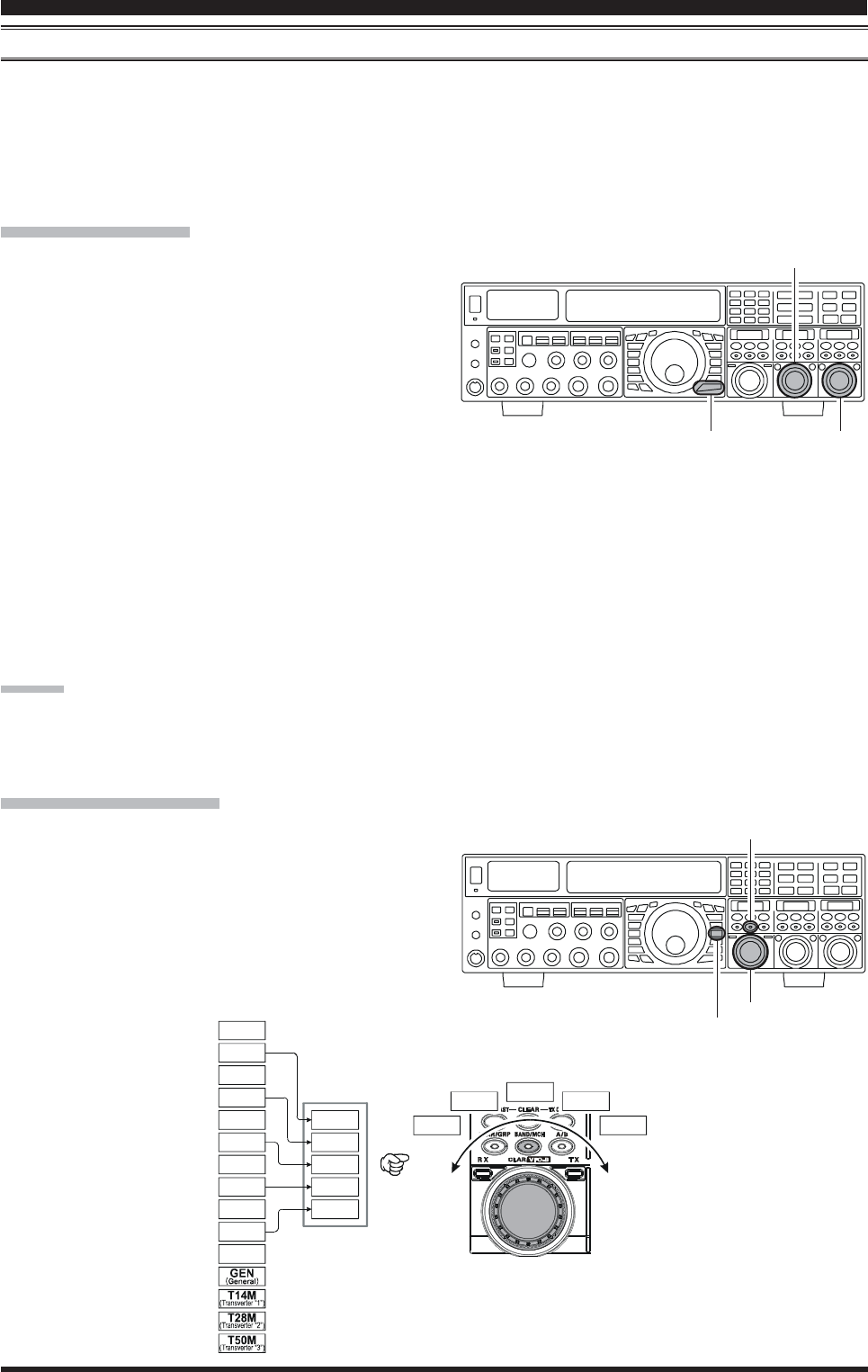
Page 46 FTDX5000 OPERATING MANUAL
“MY BANDS” OPERATION
When operating on an amateur band, it is possible to use the [BAND] buttons to engage the use of the [CLAR(VFO-B)]
knob for amateur band selection. The “My Bands” feature allows you to select several amateur bands, and make only those
bands available for selection via the [CLAR(VFO-B)] knob.
This feature can be very useful in a contest, where the 10/18/24 MHz band are not used, or if you do not have antennas for
some bands.
“My Bands” Setup
1. Press the [MENU] button to engage the Menu mode.
2. Rotate the (VFO-A)[SELECT] knob to select Menu
item “144 TUN MY BAND.”
3. Rotate the (VFO-B)[SELECT] knob to choose a band
that you wish to skip (omit) from the band-selection
loop (when using the [CLAR(VFO-B)] knob for band
selection). The available choices are 1.8M/3.5M/7M/
10M/14M/18M/21M/24M/28M/50M/GEN(General
Band)/T14M(Transverter “1”)/T28M(Transverter
“2”)/T50M(Transverter “3”).
4. Press the [ENT] button (one of the [BAND] button) to
set the selected band to “skipped”. The “ONON
ONON
ON” notation
at the right of the band notation will change to “OFFOFF
OFFOFF
OFF”.
5. Repeat steps 3 and 4 to select (“ONON
ONON
ON”) /deselect (“OFFOFF
OFFOFF
OFF”)
as many bands as you like.
6. Press and hold in the [MENU] button for two seconds
to lock in the new configuration and exit to normal
operation.
ADVICE:
The “My Band” feature affects only VFO-A band.
CONVENIENCE FEATURES
“My Band” Operation
1. Press the [V/M] button once, if neccessary, to enter the
“VFO” mode.
2. Press the [BAND/MCH] button briefly; the imbedded
LED will glow Red.
3. Rotate the [CLAR(VFO-B)] knob knob to choose the
amateur band on which you wish to operate. Only those
amateur bands that have not been skipped will appear
as you scroll through the bands.
(VFO-B)[SELECT] Knob
[MENU] Button
(VFO-A)[SELECT] Knob
[CLAR(VFO-B)] Knob
[V/M] Button
[BAND/MCH] Button
14 MHz
14 MHz
18 MHz
50 MHz
21 MHz21 MHz
7 MHz
7 MHz
5 MHz
1.8 MHz
28 MHz
28 MHz
24 MHz
3.5 MHz
3.5 MHz
10 MHz
14 MHz 21 MHz7 MHz
28 MHz3.5 MHz
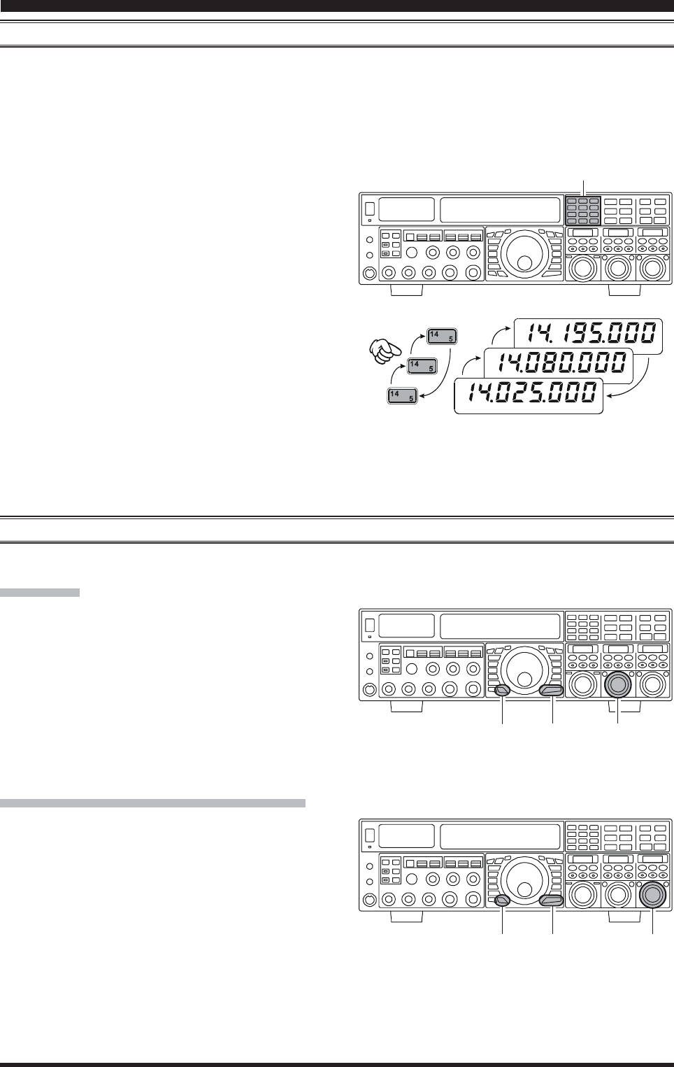
Page 47FTDX5000 OPERATING MANUAL
CONVENIENCE FEATURES
BAND STACK OPERATION
The FTDX5000 utilizes a triple band-stack VFO selection technique, that permits you to store up to three favorite frequen-
cies and modes onto each band’s VFO register. For example, you may store one frequency each on 14 MHz CW, RTTY, and
USB, then recall these VFOs by successive, momentary presses of the [14] MHz band button. Each Amateur band key may
similarly have up to three frequency/mode settings applied. Both the VFO-A and VFO-B systems have their own, indepen-
dent, band stacks.
A typical setup, for the 14 MHz band, might be arranged
like this:
1. Program 14.025 MHz, CW Mode, then press the [14]
MHz band button;
2. Program 14.080 MHz, RTTY Mode, then press the [14]
MHz band button;
3. Program 14.195 MHz, SSB Mode, then press the [14]
MHz band button.
With this configuration, successive momentary presses of
the [14] MHz band button will allow you to toggle se-
quentially through these three VFOs.
C.S (CUSTOM SWITCH)
An often-used Menu mode selection may be brought out to the front panel’s [C.S] button.
C.S Setup
1. Press the [MENU] button to engage the Menu mode;
the Menu list will appear on the SUB DISPLAYs.
2. Rotate the (VFO-A)[SELECT] knob to select the
Menu item you want to be able to access via the [C.S]
button.
3. Press and hold in the [C.S] button for two seconds to
lock in your selection.
4. Press and hold in the [MENU] button for two seconds
to save the new configuration and exit to normal op-
eration.
Menu Selection Recall via [C.S] button
1. Press the [C.S] button. The programmed Menu item
will appear on the display.
2. You may now rotate the (VFO-B)[SELECT] knob to
change the setting of this menu item.
3. Press the [MENU] button for two seconds, when you
are done, to save the new configuration and exit to
normal operation.
USB
RTTY
CW
(VFO-A)[SELECT] Knob
[MENU] Button
[C.S] Button
(VFO-B)[SELECT] Knob
[MENU] Button
[C.S] Button
[BAND] Button
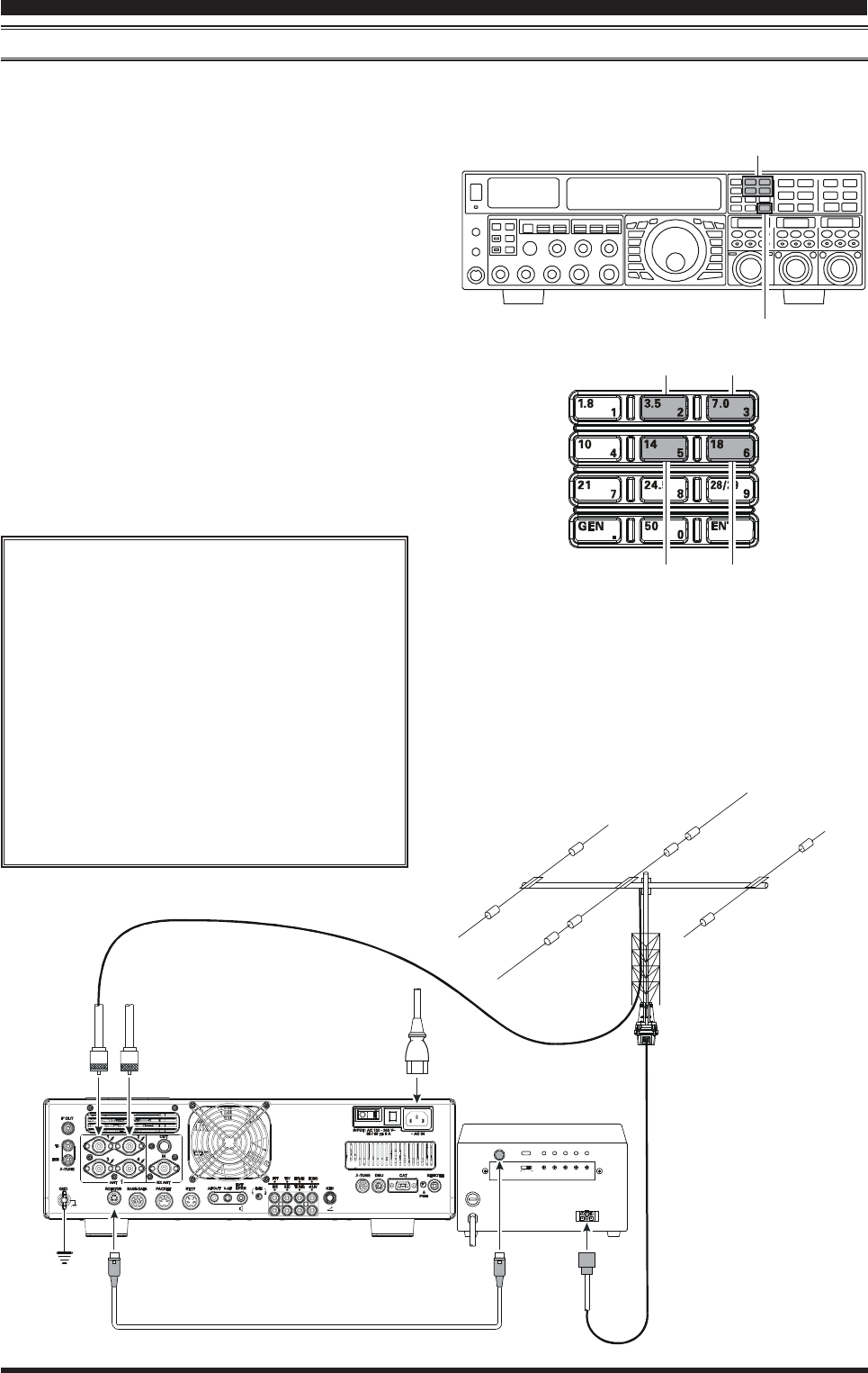
Page 48 FTDX5000 OPERATING MANUAL
ROTATOR CONTROL FUNCTIONS
When using a YAESU model G-800DXA, G-1000DXA, or G-2800DXA rotator (not supplied), it is possible to control it
from the front panel of the FT-2000D.
1 Press and hold in the [ENT] button (one of the [BAND]
button) for two seconds. The SUB DISPLAYs will
change over to the “Rotator Control” configuration.
2 Press either the [3.5(2)] button or the [7.0(3)] button
to rotate the antenna. Pressing the [3.5(2)] button will
cause rotation to the left (counter-clockwise), while
pressing the [7.0(3)] button will cause rotation to the
right (clockwise).
3 Press the [14(5)] button or the [18(6)] button to con-
trol the speed of rotation. Pressing the [14(5)] button
will cause slower rotation, while pressing the [18(6)]
button will speed up rotation. Usually, you will be us-
ing the “100%” setting.
When you are through exercising rotator control, press the
[ENT] button briefly. The SUB DISPLAYs will return to
the normal display.
CONVENIENCE FEATURES
IMPORTANT NOTE
Set to match the starting point of your rotator
control indicator needle via the Menu item “012
DISP RTR STU.” The default setting is zero
(north). If your controller starting point is south,
the Menu item “012 DISP RTR STU” must be
set to “180°180°
180°180°
180°.” If not set properly the FTDX5000
display will not show the correct direction.
When the rotator control indicator needle does
not indicate the precise antenna direction, ad-
justs the indicator needle precisely to the an-
tenna direction via the Menu item “013 DISP
RTR ADJ.”
[ENT] Button
[3.5(2)], [7(3)] Button
[14(5)], [18(6)] Button
ANT 1
~AC IN
ANT 2
EXT CONTROL
REMOTE
CONTROL
ROT
EXT
CONTROL
SELECT
SWITCH
PRESET
ADJ
OPERATION
MODE
ADJ. MODE FULL
SCALE
ADJ
OVERLAP
LED ADJ
OUT VOL
ADJ
AB
OPTIONAL CONNECTION CABLE
()
T9101556
Counter-clockwise Rotation Clockwise Rotation
Speed Down Speed Up
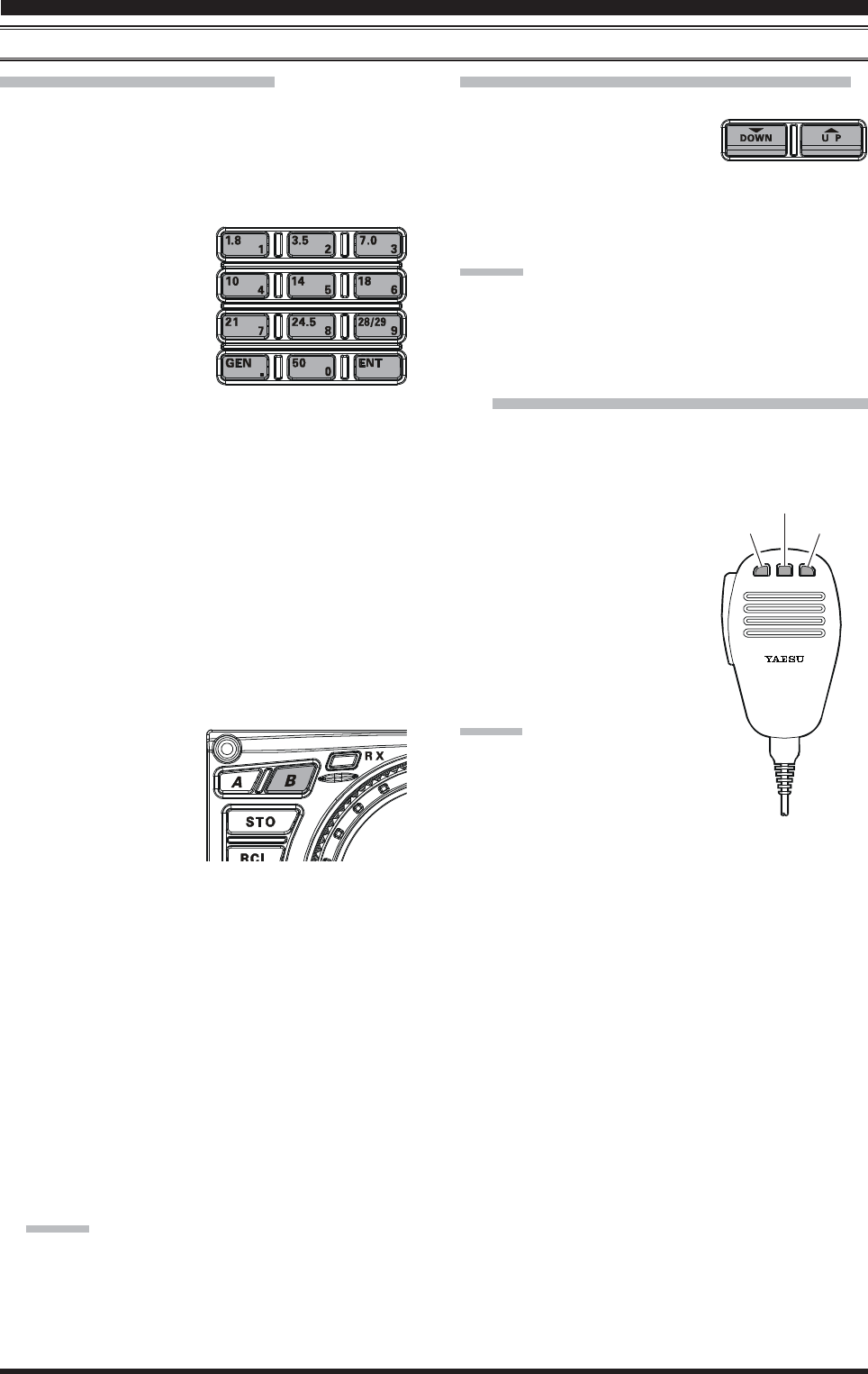
Page 49FTDX5000 OPERATING MANUAL
MORE FREQUENCY NAVIGATION TECHNIQUES
Keyboard Frequency Entry
You may enter operating frequencies, for either the VFO-
A or VFO-B bands, using the front panel band/frequency
selection keys.
Example 1: Enter 14.250.000 MHz into the VFO-A
1. Press the [ENT] button to engage the direct frequency
entry process. Now, be-
ginning with the “10
MHz” digit of the fre-
quency (the leftmost
digit), we will enter the
required digits of the fre-
quency.
2. Press, in order, the digits of the operating frequency,
using the [BAND] buttons (which have the frequency-
entry digit or decimal point on the right side of the
slash bar). In this example, enter
[1.8/1] Æ [10/4] Æ[GEN/.] Æ [3.5/2] Æ
[14/5] Æ [50/0] Æ [50/0] Æ [50/0] Æ [50/0]
The decimal point after the “MHz” portion of the fre-
quency must be entered, but no decimal point is re-
quired after the “kHz” portion.
3. Press the [ENT] button once more. A short “beep” will
confirm that the frequency entry was successful, and
the new operating frequency will appear on the Main
(VFO-A) frequency display fields.
Example 2: Enter 7.100.000 MHz into the VFO-B
1. Press the [B] button, lo-
cated to the upper left of
the Main Tuning Dial
knob. The imbedded
LED in the [B] button is
glows orange.
2. Press the [ENT] button to engage the direct frequency
entry process. Now, beginning with the “10 MHz” digit
of the frequency (the leftmost digit), we will enter the
required digits of the frequency to be entered into the
VFO-B register.
3. Press, in order, the digits of the operating frequency,
using the [BAND] buttons (which have the frequency-
entry digit or decimal point on the right side of the
slash bar). In this example, enter
[21/7] Æ [GEN/.] Æ [1.8/1] Æ
[50/0] Æ [50/0] Æ [50/0] Æ [50/0] Æ [50/0]
4. Press the [ENT] button once more. A short “beep” will
confirm that the frequency entry was successful, and
the new operating frequency will appear on the VFO-
B frequency display fields.
ADVICE:
If you attempt to enter a frequency outside the operat-
ing range of 30 kHz ~ 60 MHz, the microprocessor
will ignore the attempt, and you will be returned to
your previous operating frequency. If this happens,
please try again, taking care not to repeat the error in
the frequency entry process.
Using the [T(DOWN)]/[S(UP)] Buttons
Press the [T(DOWN)]/[S(UP)] button to tune the
VFO-A frequency in 1 MHz
step.
Press the [B] button first (The imbedded LED in the
[B] button is glows orange), then press the
[T(DOWN)]/[S(UP)] button to tune the VFO-B fre-
quency in 1 MHz step.
ADVICE::
::
:
You may change the tuning step of the [T(DOWN)]/
[S(UP)] button to 100 kHz via the Menu item “140 TUN
MHz SEL”. See page 127.
Using the [UP]/[DWN] Switches of the
Supplied MH-31B8 Hand Microphone
The [UP]/[DWN] switches on the supplied MH-31B8 Hand
Microphone may also be used for manually scanning up-
ward or downward in frequency, respectively.
The microphone’s [UP]/[DWN]
switches utilize the tuning steps
of the Main Tuning Dial knob;
moreover, when the microphone’s
[FAST] key is pressed, the tuning
rate increases by a factor of ten, in
a manner similar to the effect of the
transceiver’s front-panel [FAST]
button.
ADVICE:
In the AM and FM modes, you may in-
dependently set the tuning steps when
using the [UP]/[DWN] switches. To set
new tuning steps, use Menu items “141
TUN AM STEP” and “142 TUN FM STEP”.
CONVENIENCE FEATURES
DYNAMIC MICROPHONE
MH-31
DWN FST UP
[DWN] Button
[FST] Button
[UP] Button
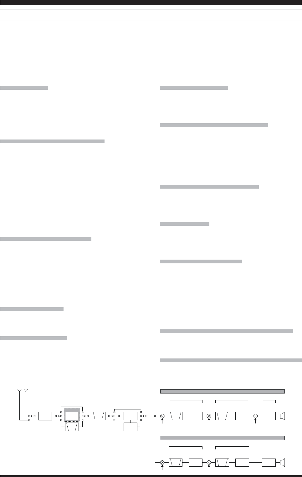
Page 50 FTDX5000 OPERATING MANUAL
RECEIVER OPERATION (FRONT END BLOCK DIAGRAM)
The FTDX5000 includes a wide range of special features to suppress the many types of interference that may be encoun-
tered on the HF bands. However, real world interference conditions are constantly changing, so optimum setting of the
controls is somewhat of an art, requiring familiarity with the types of interference and the subtle effects of some of the
controls. Therefore, the following information is provided as a general guideline for typical situations, and a starting point
for your own experimentation.
We provide the RF-TUNING Unit (Narrow-bandwidth High-Q RF Filter) for the option.
VRF (SEE PAGE 53)
On the 1.9 - 28 MHz amateur bands, Yaesu’s powerful
VRF (Variable RF Filter) preselector circuit provides ex-
cellent suppression of out-of-band interference, with a
passband much narrower than that provided by traditional
fixed bandpass filters.
R. FLT (IF Roofing Filters) (SEE PAGE 54)
On the VFO-A receiver, three automatically-selected Roof-
ing filters, in bandwidths of 15 kHz, 6 kHz, 3 kHz, 600
Hz, and 300 Hz are provided in the 9 MHz First IF, right
after the first mixer. These filters provide narrow-band se-
lectivity to protect the following IF and DSP stages, and
the filters' automatically-selected bandwidths may be
manually changed by the operator, if desired, for special
operating circumstances.
The VFO-B receiver’s 40 MHz IF includes a fixed Roof-
ing filter, with a bandwidth of 15 kHz, 6 kHz, and 3 kHz.
CONTOUR Filter (SEE PAGE 55)
The DSP Contour filter is a unique capability on the
FTDX5000, providing either nulling or peaking of tunable
segments of the receiver passband, so as to suppress inter-
ference or excessive frequency components on an incom-
ing signal, or to peak those tunable frequency segments.
The amount of nulling/peaking, and the bandwidth over
which it is applied, are adjustable via the Menu.
IF SHIFT (SEE PAGE 56)
The passband center frequency response of the IF DSP
filtering may be adjusted using this control.
IF WIDTH (SEE PAGE 57)
The width of the IF DSP filtering may be adjusted using
this control.
IF NOTCH (SEE PAGE 58)
The IF Notch filter is a high-Q notch filter that can signifi-
cantly reduce, if not eliminate, an interfering carrier. The
Q (sharpness) of the filter may be adjusted using the Menu.
DNR (DIGITAL NOISE REDUCTION) (SEE PAGE 59)
The DSP’s Digital Noise Reduction (DNR) feature uti-
lizes sixteen different mathematical algorithms to analyze
and suppress different noise profiles encountered on the
HF/50 MHz bands. Choose the selection that provides the
best noise suppression, which concurrently will allow the
signal to rise up out of the noise.
DNF (DIGITAL NOTCH FILTER) (SEE PAGE 59)
When multiple interfering carriers are encountered during
reception, the Digital Notch Filter can significantly reduce
the level of these signals.
AGC (SEE PAGE 62)
The AGC system is highly adaptable to changing signal
and fading characteristics, making reception possible un-
der the most difficult conditions.
SLOPED AGC (SEE PAGE 63)
The Sloped AGC system, instead of clamping a fixed up-
per bound on audio output across a wide range of input
signals, actually allows the audio output to rise, very gen-
tly, with ever-increasing signal strength. This capability
allows you to separate signals, using your brain, accord-
ing to signal strength in addition to slight frequency dif-
ferences.
IF Filter Quality Adjustment (SEE PAGE 125)
The “Q” (quality factor) of the IF DSP filters may be ad-
justed using the Menu.
Variable IF Filter Shape Factor (SEE PAGE 125)
You may adjust the shape factor of the receiver IF DSP
filters using the Menu.
CONVENIENCE FEATURES
ROOFING
FILTER
ROOFING
FILTER
RF
ANTENNA
SELECTOR
1st IF
1st IF
2nd IF
2nd IF
3rd IF (DSP)
69.450 MHz
40.455 MHz
450 kHz
455 kHz
30 kHz
BPF RF AMP 1
RF AMP 2
1st
IF AMP
1st
IF AMP
2nd
IF AMP
2nd
IF AMP
DSP
UNIT
DET
1st Local
1st Local
3k/6k/15k
15k
2nd Local
2nd Local
3rd Local
CF
CF
IPO OFF
VRF
μ-TUNE
Main Band VFO-A
()
Sub Band VFO-B
()
OPTION
AT T
THRU
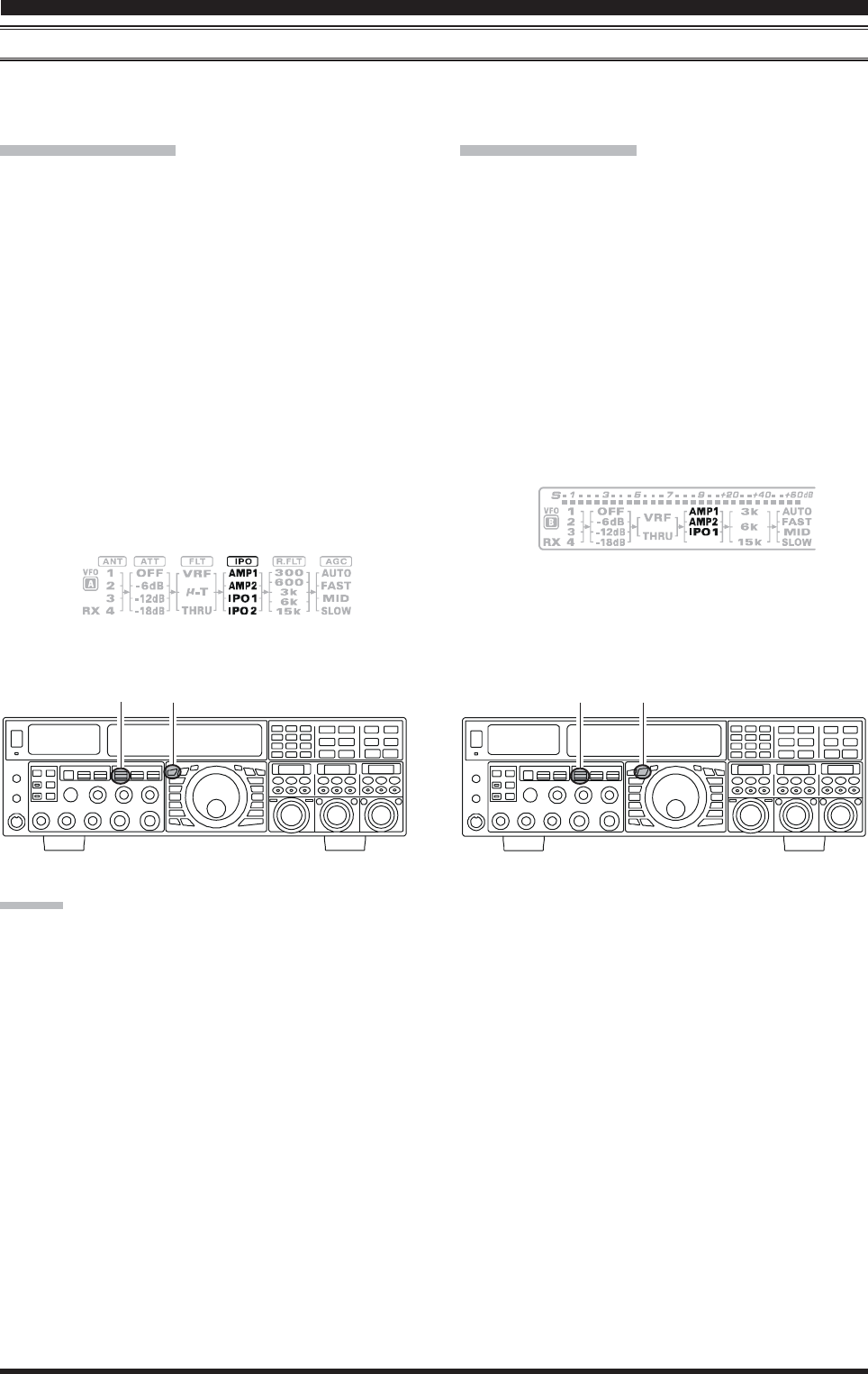
Page 51FTDX5000 OPERATING MANUAL
IPO (INTERCEPT POINT OPTIMIZATION)
The IPO feature allows the operator to optimize the characteristics of the receiver front end, depending on the current noise
level and the strength of incoming signals.
VFO-A IPO Setup
Press the [A] button (the imbedded LED in the [A]
button is glows red), if desired.
Move the [IPO] knob up and down to set the desired
characteristic of the VFO-A receiver front end, per the
chart below.
AMP1AMP1
AMP1AMP1
AMP1: Amplifies the incoming signal path using a
low distortion RF preamplifier (normally, the
IPO selection is set to this position).
AMP2AMP2
AMP2AMP2
AMP2: Increases the sensitivity.
IPO1IPO1
IPO1IPO1
IPO1: Improves the IPO.
IPO2IPO2
IPO2IPO2
IPO2: Bypasses the RF preamplifier, yielding di-
rect feed to the first mixer. As a result, the
IPO is improved more.
The selected receiver RF preamplifier will be indicated
in the IPO column of the Block Diagram Display on
the display.
CONVENIENCE FEATURES
VFO-B IPO Setup
Press the [B] button (the imbedded LED in the [B]
button is glows orange).
Move the [IPO] knob up and down to set the desired
characteristic of the VFO-B receiver front end, per the
chart below.
AMP1AMP1
AMP1AMP1
AMP1: Amplifies the incoming signal path using a
low distortion RF preamplifier (normally, the
IPO selection is set to this position).
AMP2AMP2
AMP2AMP2
AMP2: Increases the sensitivity.
IPO1IPO1
IPO1IPO1
IPO1: Improves the IPO.
The selected receiver RF preamplifier will be indicated
in the IPO column of the Block Diagram Display on
the display.
ADVICE:
On the 10 MHz and lower bands, it generally is not necessary to use any preamplifier at all; selecting the “ONON
ONON
ON” position
described above will increase the strong-signal-handling capability of the receiver, and generally will result in more pleas-
ant reception due to reduced noise. If you can hear band noise with the preamplifiers disengaged, then a preamplifier is
generally not needed.
[A] Button
[IPO] Knob [B] Button
[IPO] Knob
Press the [IPO] knob briefly to select the IPO setting
to “AMP1” for quick selection.
Press the [IPO] knob briefly to select the IPO setting
to “AMP1” for quick selection.
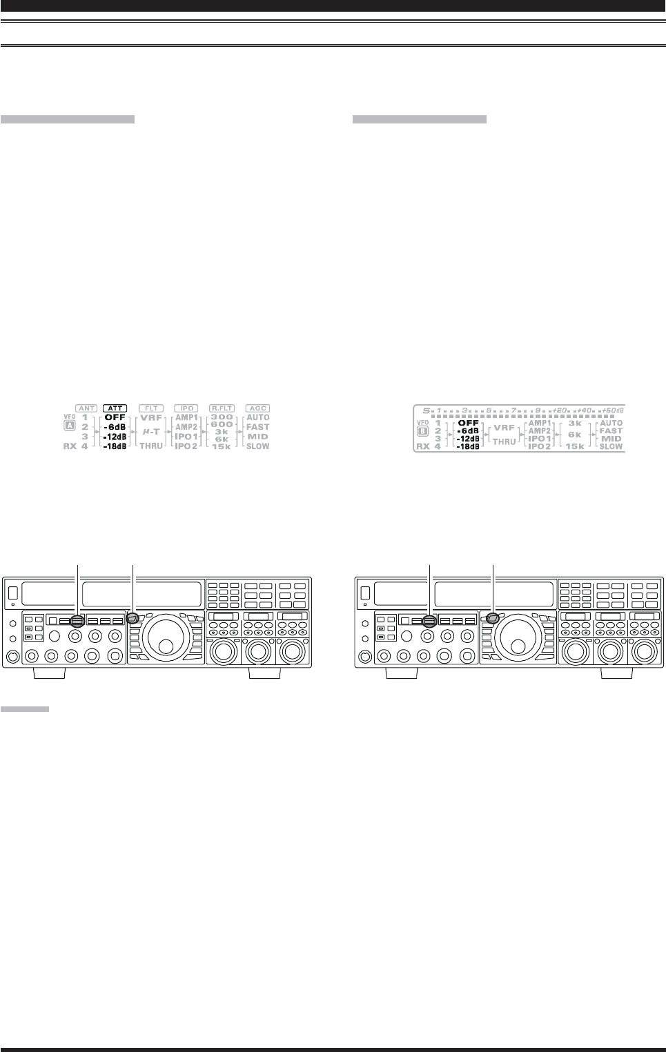
Page 52 FTDX5000 OPERATING MANUAL
ATT
Even with the IPO function on, extremely strong local signals or high noise can still degrade reception. In such situations,
you can use the [ATT] button to insert 6, 12, or 18-dB of RF attenuation in front of the RF amplifier.
VFO-A IPO Setup
Press the [A] button (the imbedded LED in the [A]
button is glows red), if desired.
Move the [ATT] knob up and down to set the desired
attenuation level of the VFO-A receiver, per the chart
below.
OFFOFF
OFFOFF
OFF: Attenuator is Off
–6 dB6 dB
6 dB6 dB
6 dB: The incoming signal power is reduced by 6
dB (Signal voltage reduced by 1/2)
–12 dB12 dB
12 dB12 dB
12 dB: The incoming signal power is reduced by 12
dB (Signal voltage reduced by 1/4)
–18 dB18 dB
18 dB18 dB
18 dB: The incoming signal power is reduced by 18
dB (Signal voltage reduced by 1/8)
The selected attenuation level will be indicated in the
ATT column of the Block Diagram Display on the dis-
play.
VFO-A IPO Setup
Press the [B] button (the imbedded LED in the [B]
button is glows orange).
Move the [ATT] knob up and down to set the desired
attenuation level of the VFO-B receiver, per the chart
below.
OFFOFF
OFFOFF
OFF: Attenuator is Off
–6 dB6 dB
6 dB6 dB
6 dB: The incoming signal power is reduced by 6
dB (Signal voltage reduced by 1/2)
–12 dB12 dB
12 dB12 dB
12 dB: The incoming signal power is reduced by 12
dB (Signal voltage reduced by 1/4)
–18 dB18 dB
18 dB18 dB
18 dB: The incoming signal power is reduced by 18
dB (Signal voltage reduced by 1/8)
The selected attenuation level will be indicated in the
ATT column of the Block Diagram Display on the dis-
play.
ADVICE::
::
:
If background noise causes the S-meter to deflect on clear frequencies, move the [ATT] knob until the S-meter drops to
about “S-1”. This setting optimizes the trade-offs between sensitivity, noise, and interference immunity. Also, once you
have tuned in a station you want to work, you may want to reduce sensitivity further (or add more attenuation) by moving
the [ATT] knob to a more setting. This reduces the strength of all signals (and noise) and can make reception more comfort-
able, important especially during long QSOs. When looking for weak signals on a quiet band, you will want maximum
sensitivity, so the IPO should be disabled and the [ATT] knob should be set to “OFFOFF
OFFOFF
OFF” by pressing the [ATT] knob. This
situation is typical during quiet times on frequencies above 21 MHz, and when using a small or negative-gain receiving
antenna on other bands.
To restore full signal strength through the Attenuator
circuit area, press the [ATT] knob briefly to select the
ATT setting to “OFF” for quick selection or move the
[ATT] knob to restore the ATT display to the “OFF”
position.
To restore full signal strength through the Attenuator
circuit area, press the [ATT] knob briefly to select the
ATT setting to “OFF” for quick selection or move the
[ATT] knob to restore the ATT display to the “OFF”
position.
[A] Button
[ATT] Knob [B] Button
[ATT] Knob
CONVENIENCE FEATURES
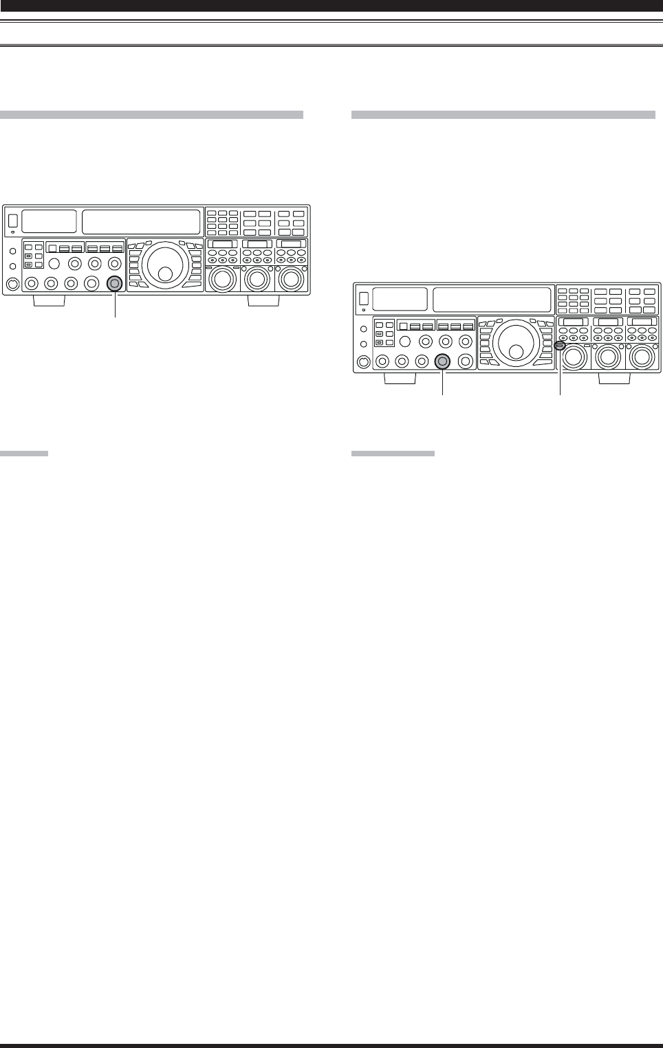
Page 53FTDX5000 OPERATING MANUAL
CONVENIENCE FEATURES
RF GAIN (SSB/CW/AM MODES)
The RF Gain controls provide manual adjustment of the gain levels for the receiver RF and IF stages, to account for noise
and/or signal strength conditions at the moment.
VFO-A Receiver’s RF GAIN Adjustment
The (VFO-A)[RF GAIN] knob should, initially, be ro-
tated to the fully clockwise position. This is the point of
maximum sensitivity, and counter-clockwise rotation will
gradually reduce the system gain.
VFO-B Receiver’s RF GAIN Adjustment
The VFO-B receiver’s RF Gain operates identically to the
VFO-A receiver’s RF Gain.
Press the (VFO-B)[RX] button to engage the Dual
Receive operation. The imbedded LED in the (VFO-
B)[RX] button is glows green.
The fully clockwise position of the (VFO-B)[RF
GAIN] knob should always be utilized as a starting
point for operation.
ADVICE:
As the [RF GAIN] knob is rotated counterclockwise
to reduce the gain, the S-meter reading will rise. This
indicates that the AGC voltage being applied to the
receiver is increasing (which causes a reduction in re-
ceiver gain).
Rotating the [RF GAIN] knob control to the fully
counter-clockwise position will essentially disable the
receiver, as the gain will be greatly reduced. In this
case, as well, the S-meter will appear to be “pegged”
against the right edge of the analog S-meter scale.
The (VFO-B)[RF GAIN] knob operates identically to
the (VFO-A)[RF GAIN] knob. The effects of counter-
clockwise rotation of the VFO-B receiver’s RF Gain
control may be observed visually on the VFO-B S-
meter.
QUICK POINT:
Reception frequently can be optimized by rotating the
[RF GAIN] knob slightly counter-clockwise to the
point where the incoming noise level is just about the
same as the “stationary” meter needle position as set
by the adjustment of the [RF GAIN] knob. This set-
ting ensures that excessive gain is not being utilized,
without so much gain reduction that incoming signals
cannot be heard.
The RF GAIN control, along with the IPO and
ATT(enuator) features, all affect the system receiver
gain in different ways. As a first step in dealing with
high noise or a crowded, high-level signal environment,
the IPO generally should be the first feature engaged,
if the frequency is low enough to allow the preampli-
fier to be bypassed. Thereafter, the RF GAIN and
ATT(enuator) features may be employed to provide
precise, delicate adjustment of the receiver gain so as
to optimize performance fully.
(VFO-A)[RF GAIN] Knob
(VFO-B)[RF GAIN] Knob (VFO-B)[RX] Button
HIJKHIJKHIJKHIJKHIJKHIJKHIJKHIJKHIJKHIJKHIJKHIJKHIJKHIJKHIJKHIJKHIJKHIJKHIJKHIJKHIJKHIJKHIJKHIJKHIJKHIJKHIJKHIJK
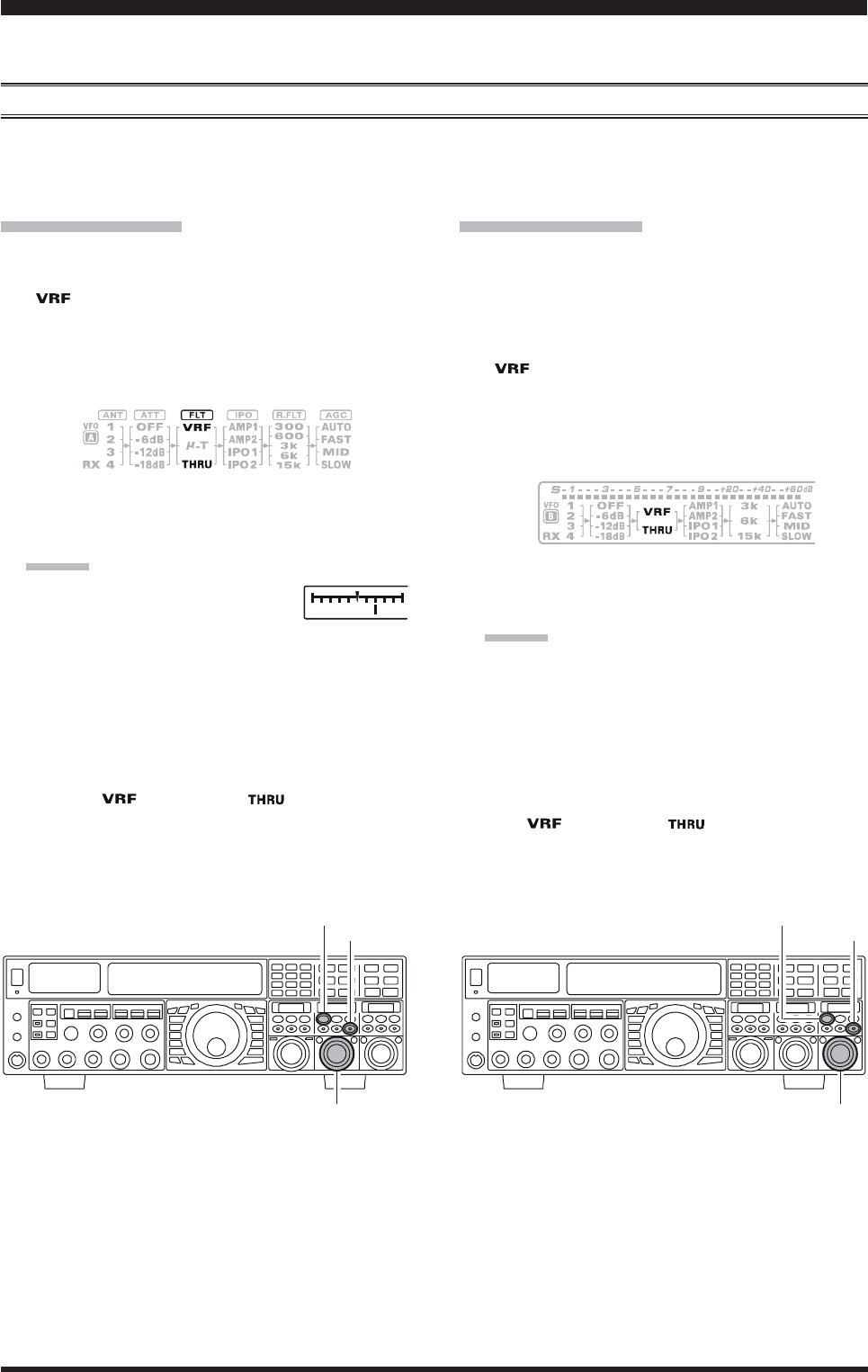
Page 54 FTDX5000 OPERATING MANUAL
The FTDX5000 includes an unmatched array of RF selectivity-enhancing features. Please study the material below care-
fully, so as to understand the various features completely.
USING THE VRF (VARIABLE RF FRONT-END FILTER)
The VRF system is a high-performance RF front-end preselector that has high Q factor and low insertion loss. VRF pro-
vides outstanding rejection of out-of-band signals, and can significantly improve reception in tough co-location operations
such as a contest or DX-pedition. The FTDX500’s VRF system affects the 1.8 - 28 MHz amateur bands only.
A
DVANCED
I
NTERFERENCE
-S
UPPRESSION
F
EATURES
:
RF F
RONT
E
ND
VFO-A VRF Setup
Press the (VFO-A)[VRF] button. The imbedded LED
in the (VFO-A)[VRF] button is glows red, and the
“” icon will appear at the FLT column of the Block
Diagram Display on the display. The VRF system will
be engaged, centered on your current amateur band.
The (VFO-A)[SELECT] knob will now functions as
the VRF knob.
VFO-B VRF Setup
Press the (VFO-B)[RX] button to engage the Dual
Receive operation. The imbedded LED in the (VFO-
B)[RX] button is glows green.
Press the (VFO-B)[VRF] button. The imbedded LED
in the (VFO-B)[VRF] button is glows red, and the
“” icon will appear at the FLT column of the Block
Diagram Display on the display. The VRF system will
be engaged, centered on your current amateur band.
The (VFO-B)[SELECT] knob will now functions as
the VRF knob.
(VFO-A)[SELECT] Knob
[CLEAR] Button
(VFO-A)[VRF/-T] Button
(VFO-B)[SELECT] Knob
[CLEAR] Button
(VFO-B)[VRF] Button
You may rotate the (VFO-A)[SELECT] knob to skew
the position of the VRF system relative to your operat-
ing frequency.
ADVICE:
You may observe the relative skew
of the VRF system in the Tuning
Offset Indicator on the display and the SUB DIS-
PLAY-II.
After moving the passband of the VRF system
manually, you may re-center it on the current Ama-
teur band by pressing the (VFO-A)[CLEAR] but-
ton.
To switch VRF off, press the (VFO-A)[VRF] button
until the “ ” icon shows “ ” in the FLT col-
umn of the Block Diagram Display on the display; this
confirms that the VRF circuit has been removed from
the incoming received signal path.
You may rotate the (VFO-B)[SELECT] knob to skew
the position of the VRF system relative to your operat-
ing frequency.
ADVICE:
You may observe the relative skew of the VRF sys-
tem in the SUB DISPLAY-III.
After moving the passband of the VRF system
manually, you may re-center it on the current Ama-
teur band by pressing the (VFO-B)[CLEAR] but-
ton.
To switch VRF off, press the (VFO-B)[VRF] button.
The “ ” icon shows “ ” in the FLT column of
the Block Diagram Display on the display; this con-
firms that the VRF circuit has been removed from the
incoming received signal path.
Page 55FTDX5000 OPERATING MANUAL
ADVICE::
::
:
Because the VRF system is relatively broad, although
still much narrower than the fixed bandpass filter), you
may not hear much difference in the background noise
or signal quality when you make minor adjustments.
However, if you have receiving problems associated
by a very strong signal, rotation of the [SELECT] knob
may help reduce the strength of the interfering station,
allowing improved reception of the desired signal if
overload was degrading reception.
The VRF Filter operational status will be memorized
independently on each VFO in the VFO stack.
QUICK POINT:
The VRF filter, utilizing high-quality coils and capacitors
that provide high Q, yields a passband that is approximately
20% to 30% the width of a traditional, fixed bandpass fil-
ter. As a result, significantly more “unwanted” signal re-
jection is provided. Within each amateur band, the fol-
lowing adjustment steps are provided, if you wish to skew
the response in a particular direction so as to enhance in-
terference rejection even more. The actual “sound” of the
signal you are listening to will remain unchanged, how-
ever.
AMATEUR BAND
1.8 MHz
3.5 MHz
5 MHz
7 MHz
10 MHz
14 MHz
18 MHz
21 MHz
24.5 MHz
28 MHz
VRF ADJUSTMENT STEPS
62 steps
62 steps
62 steps
62 steps
30 steps
30 steps
20 steps
20 steps
20 steps
20 steps
A
DVANCED
I
NTERFERENCE
-S
UPPRESSION
F
EATURES
:
RF F
RONT
E
ND
USING THE VRF (VARIABLE RF FRONT-END FILTER)
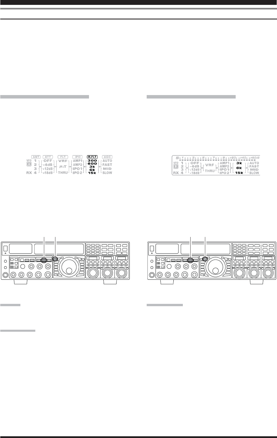
Page 56 FTDX5000 OPERATING MANUAL
R.FLT (ROOFING FILTERS)
Narrow-band Roofing Filters of 15 kHz, 6 kHz, 3 kHz, 600 HzÚ, and 300 HzÚ bandwidths are provided in the first IF, right
after the first mixer. These filters provide protection fort the 2nd mixer, DSP, and other circuitry that follow and can
dramatically improve reception on a very crowded band (during a contest, etc.). Typically, the AUTO selection mode is
satisfactory for most operating situations, but in an extremely crowded phone band you may wish to select, for example, the
3 kHz roofing filter for SSB operation.
Ú:The roofing filter of 600 Hz is select in VFO-A only (The roof filter of 600Hz can not select in VFO-B). Furthermore,
the roofing filter of 300 Hz is select in VFO-A of the MP version only (The roof filter of 300Hz is optional in the other
versions).
I
NTERFERENCE
R
EJECTION
(S
IGNALS
O
FF
F
REQUENCY
BY
J
UST
A
F
EW
KHZ
)
VFO-A Roofing Filter Setup
Press the [A] button (the imbedded LED in the [A]
button is glows red), if desired.
Move the [R.FLT] knob up and down to set the de-
sired bandwidth of the VFO-A Roofing Filter.
The selected bandwidth of the Roofing Filter will be
indicated in the R.FLT column of the Receiver Con-
figuration Indicator on the display.
VFO-B Roofing Filter Setup
Press the [B] button (the imbedded LED in the [B]
button is glows orange).
Move the [R.FLT] knob up and down to set the de-
sired bandwidth of the VFO-B Roofing Filter.
The selected bandwidth of the Roofing Filter will be
indicated in the R.FLT column of the Receiver Con-
figuration Indicator on the display.
ADVICE:
The Roofing Filter selection will be memorized inde-
pendently on each VFO in the VFO stack.
QUICK POINT:
The AUTO mode Roofing Filter selections are shown
below:
AM/FM/FM-PKT: 15 kHz
LSB/USB/PKT: 6 kHz
CW/RTTY: 3 kHz
Press the [R.FLT] knob briefly to select the Roofing
Filter setting to “AUTO”, that selection of the Roofing
Filter is based on the operating mode. When the Roof-
ing Filter setting is to “AUTO”, the bandwhidth of the
Roofing Filter will blink for three seconds and there-
after will appear continuously. Typically, this selection
will be set to “AUTO”.
TERMINOLOGY:
A “Roofing Filter,” as its name implies, places a “Roof”
over the receiver’s IF system bandwidth. This “Roof” pro-
tects the circuitry downstream from the first mixer from
interference, just as a roof on a house protects the contents
from rain and snow.
[A] Button
[R.FLT] Knob [B] Button
[R.FLT] Knob
HIJKHIJKHIJKHIJKHIJKHIJKHIJKHIJKHIJKHIJKHIJKHIJKHIJKHIJKHIJKHIJKHIJKHIJKHIJKHIJKHIJKHIJKHIJKHIJKHIJKHIJKHIJKHIJK

Page 57FTDX5000 OPERATING MANUAL
A
DVANCED
I
NTERFERENCE
-S
UPPRESSION
F
EATURES
:
RF F
RONT
E
ND
NOTE
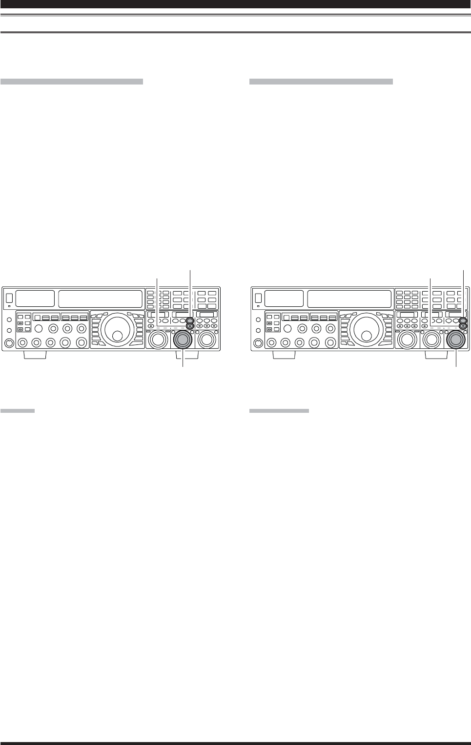
Page 58 FTDX5000 OPERATING MANUAL
CONTOUR CONTROL OPERATION
The Contour filtering system provides a gentle perturbation of the IF filter passband, so as to suppress or enhance certain
frequency components, thus enhancing the sound and/or readability of a received signal.
I
NTERFERENCE
R
EJECTION
(S
IGNALS
WITHIN
3
KHZ
)
VFO-A Contour Operation
Press the (VFO-A)[CONT/APF] button. The imbed-
ded LED in the (VFO-A)[CONT/APF] button is glows
red, and current “null” (or “Peak”) position of the con-
tour filter will appears in the SUB DISPLAY-II . The
(VFO-A)[SELECT] knob will now functions as the
contour knob.
Rotate the (VFO-A)[SELECT] knob to achieve the
most natural-sounding audio reproduction on the in-
coming signal.
Press the (VFO-A)[CLEAR] button to move the “null”
(or “Peak”) position to center.
To cancel Contour tuning, press the (VFO-A)[CONT/
APF] button once more.
ADVICE:
The contour filter’s level (either nulling or peaking)
may be adjusted using Menu item “108 RDSP CNTR
LV”. The factory default setting is for a null of “–15–15
–15–15
–15”
(dB).
The bandwidth over which the contour filter effect is
applied may be adjusted using Menu item “109 RDSP
CNTR WI.” The factory default setting is “1010
1010
10.”
When the optional DMU-2000 Data Management Unit
is connected, the Audio Scope (on the “Oscilloscope”
page) is particularly useful when adjusting the Con-
tour control. Not only can you see the effect of the
null/peak of the Contour system, but you also can see
the position of the null/peak with respect to frequency
components of interest on the incoming signal. You
may then observe (on the Audio Scope) the effect of
the Contour control while listening to the effect on the
signal, and this will help build your intuition on how
best to use Contour tuning in the future.
VFO-B Contour Operation
Press the (VFO-B)[CONT/APF] button. The imbed-
ded LED in the (VFO-B)[CONT/APF] button is glows
red, and current “null” (or “Peak”) position of the con-
tour filter will appears in the SUB DISPLAY-III. The
(VFO-B)[SELECT] knob will now functions as the
contour knob.
Rotate the (VFO-B)[SELECT] knob to achieve the
most natural-sounding audio reproduction on the in-
coming signal.
Press the (VFO-B)[CLEAR] button to move the “null”
(or “Peak”) position to center.
To cancel Contour tuning, press the (VFO-A)[CONT/
APF] button once more.
(VFO-A)[SELECT] Knob (VFO-B)[SELECT] Knob
(VFO-B)[CONT/APF] Button
[CLEAR] Button
(VFO-A)[CONT/APF] Button
[CLEAR] Button
QUICK POINT:
The steep slopes of the DSP filtering can, when adjusted
aggressively, impart an unnatural sound to an incoming
signal. Oftentimes, though, a narrow bandwidth is not the
key to improving copy; the incoming signal itself may have
undesirable or excessive frequency components, especially
in the low-frequency range around 100-400 Hz. By judi-
cious use of the Contour filter, the “shoulder” of the pass-
band response may be altered, or components removed
from within the passband, allowing the desired signal to
rise above the background noise and interference in a man-
ner not obtainable with other filtering systems.
HIJKHIJKHIJKHIJKHIJKHIJKHIJKHIJKHIJKHIJKHIJKHIJKHIJKHIJKHIJKHIJKHIJKHIJKHIJKHIJKHIJKHIJKHIJKHIJKHIJKHIJKHIJKHIJK