Yaesu Musen 20361X60 HF Transceiver with Scanning Receiver User Manual pmd
Yaesu Musen Co., Ltd. HF Transceiver with Scanning Receiver pmd
UserManual.wiki
>
Yaesu Musen
>
20361X60 User Manual
>
Users Manual 1
Contents
1.
Users Manual 1
2.
Users Manual 2
Users Manual 1
Navigation menu
Upload a User Manual
Namespaces
Wiki Guide
HTML
PDF
Info
Views
User Manual
Discussion / Help
Navigation
![Page 16 FTDX5000 OPERATING MANUAL[POWER] SwitchPress and hold in this switch for two seconds to turnthe transceiver on, after first setting the rear panel[MAIN POWER] switch to the “I” position. Pressand hold in this switch for two seconds, similarly, toturn the transceiver off. If the rear panel [MAINPOWER] switch is set to the “O” position, the frontpanel [POWER] switch will not function.ADVICE:If you press this switch briefly while the transceiveris turned on, the transceiver’s audio will be mutedfor three seconds.This is the actual power On/Off switch for turningon the transceiver. When the rear panel [MAINPOWER] switch is set to the “I” position, poweris supplied to the OCXO to stabilize the referenceoscillator, and the remainder of the transceiver isset in a “stand-by” mode, awaiting the commandfor the transceiver to switch on via the front panel[POWER] switch. For further information on therear panel [MAIN POWER] switch, please see thediscussion on page ??.CAT IndicatorThis LED indicator will flash red when the transmitand receive serial CAT command signals are being ex-changed.ADVICE:You may disable the LED function (flashes in conjunc-tion with CAT command) via Menu item “031 GEnECAT IND.” See page ??? for details.PHONES JackA 1/4-inch, 3-contact jack accepts either monaural orstereo headphones with 2- or 3-contact plugs. When aplug is inserted, the loudspeaker is disabled. With ste-reo headphones such as the optional YH-77STA, youcan monitor both VFO-A and VFO-B receiver chan-nels at the same time during Dual Receive operation.NOTE:When wearing headphones, we recommend that youturn the AF Gain levels down to their lowest settingsbefore turning power on, to minimize the impact onyour hearing caused by audio “pops” during switch-on.KEY JackThis 1/4-inch, 3-contact jack accepts a CW key or keyerpaddles (for the built-in electronic keyer), or outputfrom an external electronic keyer. Pinout is shown onpage 15. Key up voltage is 5 V, and key down currentis 1 mA. This jack may be configured for keyer, “Bug,”“straight key,” or computer keying interface operationvia Menu item “054 A1A F-TYPE” (see page ???).There is another jack with the same name on the rearpanel, and it may be configured independently for In-ternal Keyer or pseudo-straight-key operation.NOTE:You cannot use a 2-contact plug in this jack (to do soproduces a constant “key down” condition).Microphone ConnectorThis 8-pin jack accepts input from a microphone uti-lizing a traditional YAESU HF-transceiver pinout.FRONT PANEL CONTROLS & SWITCHES](https://usermanual.wiki/Yaesu-Musen/20361X60.Users-Manual-1/User-Guide-1211678-Page-3.png)
![Page 17FTDX5000 OPERATING MANUAL[DIM] SwitchPress this button to lower the illumination intensity ofthe analog meter and the frequency display. Press itonce more to restore full brightness.ADVICE:Menu Items “008 diSP DIM MTR” and “009 diSPDIM VFD” allow you to configure the dimming lev-els for the analog meter and the frequency display in-dependently, so you can customize the brightness lev-els.[MOX] SwitchPressing this button engages the PTT (Push to Talk)circuit, to activate the transmitter (the LED inside thisbutton will glow red). It must be turned off (the redLED will be off) for reception. This button replicatesthe action of the Push to Talk (PTT) switch on the mi-crophone. When engaging the [MOX] button (the LEDinside this button glows red) or otherwise causing atransmission to be started, be certain you have eitheran antenna or 50-Ohm dummy load connected to theselected Antenna jack.[VOX] SwitchThis button enables automatic voice-actuated transmit-ter switching in the SSB, AM, and FM modes. Whileactivated, the LED inside this button glows red. Thecontrols affecting VOX operation are the front panel’s[VOX] and [DELAY] knobs. By proper adjustment ofthese controls, hands-free voice-actuated operation ispossible.[TUNE] SwitchThis is the on/off switch for the FTDX5000’s Auto-matic Antenna Tuner.Pressing this button momentarily places the antennatuner in line between the transmitter final amplifier andthe antenna jack (“ ” icon will appear in the dis-play). Reception is not affected.Pressing and holding in this button for 1/2 second, whilereceiving in an amateur band, activates the transmitterfor a few seconds while the automatic antenna tunerrematches the antenna system impedance for minimumSWR. The resulting setting is automatically stored inone of the antenna tuner’s 100 memories, for instantautomatic recall later when the receiver is tuned nearthe same frequency.Pressing this button briefly, while the Tuner is engaged,will take the Automatic Antenna tuner out of the trans-mit line.NOTE:When the Automatic Antenna Tuner is tuning itself, asignal is being transmitted. Therefore, be absolutelycertain that an antenna or dummy load is connected tothe selected antenna jack before pressing and holdingin the [TUNE] button to start antenna tuning.[MONI] (Monitor) SwitchThis button enables the transmit monitor in all modes.While activated, the “ ” icon appears in the dis-play. Adjustment of the Monitor level is accomplishedusing the [MONI] knob.ADVICE:When using headphones, the Monitor is highly usefulfor making adjustments to the Parametric Equalizer orother voice quality adjustments, because the voice qual-ity heard in the headphones is such a “natural” repro-duction of the transmitted audio quality.[PROC] (Processor) SwitchThis button enables the Speech Processor for SSBtransmission. While activated, the “ ” icon appearsin the display. Adjustment of the Processor level is ac-complished using the [PROC] knob.ADVICE:The Speech Processor is a tool for increasing theaverage power output through a compression tech-nique. However, if the [PROC] knob is advancedtoo far, the increase in compression becomescounter-productive, as intelligibility will suffer. Werecommend that you monitor the sound of your sig-nal using the Monitor (with headphones).When the optional DMU-2000 Data ManagementUnit is connected, you may use the Audio Scope/Oscilloscope page to help you adjust the setting ofthe compression level of the Speech Processor foroptimum performance using your voice and micro-phone.[RX ANT] SwitchPress this button to use the RX ANT jack on the rearpanel while receive.The “RX” icon appears in the display when the RXANT is used.[ANT 1-4] SwitchMove this knob up and down to select one of the ANT1 through 4 jack on the rear panel, and allows conve-nient antenna switching at the move of knob. The se-lected antenna jack is indicated in the ANT column ofthe Block Diagram Display on the display.ADVICE:Press this knob briefly to select the ANT 1 jack forquick selection.FRONT PANEL CONTROLS & SWITCHES](https://usermanual.wiki/Yaesu-Musen/20361X60.Users-Manual-1/User-Guide-1211678-Page-4.png)
![Page 18 FTDX5000 OPERATING MANUALFRONT PANEL CONTROLS & SWITCHES[ATT] SwitchMove this knob up and down to select the degree ofattenuation, if any, to be applied to the receiver input.Available selections are “–6 dB”, “–12 dB”, “–18 dB”,or “OFF”, and the selected attenuation level appearsin the ATT column of the Block Diagram Display onthe display.ADVICE:Press this knob briefly to select the attenuation levelto “OFF” for quick selection.The Attenuator may be used in conjunction withthe [IPO] switch to provide two stages of signalreduction when an extremely strong signal is beingreceived.[IPO] (INTERCEPT POINT OPTIMIZATION) SwitchMove this knob up and down to select the optimumfront end characteristics of the receiver circuit for avery strong-signal environment. Available selectionsare “AMP 1”, “AMP 2”, “IPO 1”, or “IPO 2”.Normally, this selection is set to “AMP1”. If you wantto increase the sensitivity, this selection selects to“AMP2”. When this selection is set to “IPO1”, the IPOis improved. When this selection is set to “IPO2”, by-passes the RF preamplifier, yielding direct feed to thefirst mixer. As a result, the IPO is improved more.ADVICE:Press this knob briefly to select the IPO setting to“AMP1” for quick selection.“IPO 2” selection can not selet in VFO-B.[R.FLT] SwitchMove this knob up and down to select the bandwidthfor the first IF Roofing Filter. Available selections are“300 Hz”, “600 Hz”, “3 kHz”, “6 kHz”, “15 kHz”, or“AUTO” (“300 Hz” and “600 Hz” are select only inVFO-A, additionally, “300 Hz” is option, except MPversion), and the selected bandwidth appears in theR.FLT column of the Block Diagram Display on thedisplay.ADVICE:Press this knob briefly to select to “AUTO” forquick selection.Because the roofing filter is in the first IF, the pro-tection it provides against interference is quite sig-nificant. When set to “AUTO”, the SSB bandwidthis 6 kHz, while CW is 3 kHz, and FM/RTTY are15 kHz. On a crowded SSB band, however, youmay wish to select the 3 kHz filter, for the maxi-mum possible interference rejection.](https://usermanual.wiki/Yaesu-Musen/20361X60.Users-Manual-1/User-Guide-1211678-Page-5.png)
![Page 19FTDX5000 OPERATING MANUALFRONT PANEL CONTROLS & SWITCHES[AGC] SwitchMove this knob up and down to select the AGC char-acteristics (receiver-recovery time) for the receiver.Available selections are FAST, MID, SLOW, or AUTO,and the selected receiver-recovery time appears at theAGC column of the Block Diagram Display on the dis-play.Hold up or hold down this knob for two seconds todisable the AGC (for testing or weak-signal reception).ADVICE:Press this knob briefly to select to AUTO for quickselection.If the AGC is set to disabled by holding up or downthe [AGC] knob, the S-meter will no longer de-flect. Additionally, you will likely encounter dis-tortion on stronger signals, as the IF amplifiers andthe following stages are probably being overloaded.[METER] SwitchThis control switch determines the function of the meterduring transmission.COMP: Indicates the speech compressor level (SSBmode only).ALC: Indicates the relative ALC voltage.PO: Indicates the average power output level.SWR: Indicates the Standing Wave Ratio (Forward:Reflected).ID: Indicates the final amplifier drain current.VDD: Indicates the final amplifier drain voltage.[MONI] [PROC] Knobs[MONI] KnobThe inner [MONI] knob adjust the audio level ofthe transmit RF monitor during transmission (rela-tive to the AF GAIN control), when activated bythe [MONI] button.[PROC] KnobThe outer [PROC] knob sets the compression (in-put) level of the transmitter Speech Processor inthe SSB, AM, and FM modes, when activated bythe [PROC] button.ADVICE:The SUB DISPLAY-III will show the relative com-pression level of the Speech Processor for 3 sec-onds whenever the outer [PROC] knob is turned.You may disable this feature (displaying the rela-tive compression level) via Menu item “015 diSPLVL IND.” See page 113 for details.(VFO-B) [NB][SQL] Knobs[NB] KnobThe inner [NB] knob adjusts the VFO-B noiseblanking level when the (analog) IF noise blankeris activated by pressing the [NB] button.[SQL] KnobThe outer [SQL] knob sets the signal level thresh-old at which the VFO-B receiver audio is muted, inall modes. It is very useful during local rag-chews,to eliminate noise between incoming transmissions.This control is normally kept fully counter-clock-wise (off), except when scanning and during FMoperation.(VFO-A) [NB][SQL] Knobs[NB] KnobThe inner [NB] knob adjusts the VFO-A noiseblanking level when the (analog) IF noise blankeris activated by pressing the [NB] button.[SQL] KnobThe outer [SQL] knob sets the signal level thresh-old at which the VFO-A receiver audio is muted, inall modes. It is very useful during local rag-chews,to eliminate noise between incoming transmissions.This control is normally kept fully counter-clock-wise (off), except when scanning and during FMoperation.](https://usermanual.wiki/Yaesu-Musen/20361X60.Users-Manual-1/User-Guide-1211678-Page-6.png)
![Page 20 FTDX5000 OPERATING MANUALFRONT PANEL CONTROLS & SWITCHES[MIC] [RF PWR] Knobs[MIC] KnobThe inner [MIC] knob adjusts the microphone in-put level for (non-processed) SSB transmission.ADVICE:If you adjust the MIC Gain while speaking in asomewhat-louder-than-normal voice level,watch the ALC level and adjust the MIC Gainso that the ALC reaches just to the right edge ofthe ALC scale. Then, when you speak in a morenormal voice level, you’ll be certain not to beover-driving the mic amplifier stage.The SUB DISPLAY-III will show the relativeMicrophone Gain level for 3 seconds wheneverthe inner [MIC] knob is turned.You may disable this feature (displaying the rela-tive Microphone Gain level) via Menu item “015diSP LVL IND.” See page 113 for details.[RF PWR] KnobThe outer [RF PWR] knob is the main RF Poweroutput control for the transceiver, active in all op-erating modes. Clockwise rotation increases thepower output. Adjust this control for the desiredpower output from the FTDX5000.ADVICE:The SUB DISPLAY-III will show the RF PowerOutput for 3 seconds whenever the outer [RFPWR] knob is turned.You may disable this feature (displaying the RFPower Output) via Menu item “015 diSP LVLIND.” See page 113 for details.[SPEED] [PITCH] Knobs[SPEED] KnobThe inner [SPEED] knob adjusts the keying speedof the internal CW keyer (4 ~ 60 WPM). Clock-wise rotation increases the sending speed.When turning this knob while pressing the[KEYER] button, the Sub (VFO-B) frequency dis-play shows the keying speed.ADVICE:The SUB DISPLAY-III will show the keying speedfor 3 seconds whenever the inner [SPEED] knobis turned.You may disable this feature (displaying the key-ing speed) via Menu item “015 diSP LVL IND.”See page ??? for details.[PITCH] KnobThe outer [PITCH] knob selects your preferred CWtone pitch (from 300 ~ 1050 Hz, in 50 Hz incre-ments). The Tx sidetone, receiver IF passband, anddisplay offset from the BFO (carrier) frequency areall affected simultaneously. The Pitch control set-ting also affects the operation of the CW TuningIndicator, as the center frequency of the CW Tun-ing Indicator will follow the setting of this control.ADVICE:The SUB DISPLAY-III will show the CW tonepitch frequency for 3 seconds whenever the outer[PITCH] knob is turned.You may disable this feature (displaying the CWtone pitch frequency) via Menu item “015 diSPLVL IND.” See page ??? for details.](https://usermanual.wiki/Yaesu-Musen/20361X60.Users-Manual-1/User-Guide-1211678-Page-7.png)
![Page 21FTDX5000 OPERATING MANUALFRONT PANEL CONTROLS & SWITCHES[VOX] [DELAY] Knobs[VOX] KnobThe inner [VOX] knob sets the gain of the VOXcircuit, to set the level of microphone audio neededto activate the transmitter during voice operationwhile the [VOX] switch is engaged. The [VOX]switch must be switched “ON” to engage the VOXcircuit.[DELAY] KnobThe outer [DELAY] knob sets the hang time of theVOX circuit for voice operation and keying delayfor CW operation.During voice operation, this knob sets the hang time,between the moment you stop speaking, and theautomatic switch from transmit back to receive.Adjust this for smooth VOX operation, so the re-ceiver is only activated when your transmission isended and you wish to receive.For CW operation, this knob sets the keying delay,between the moment you stop sending, and the au-tomatic switch from transmit back to receive dur-ing “Semi-break-in” operation. Adjust this just longenough to prevent the receiver from being restoredduring word spaces at your preferred sending speed.ADVICE:The SUB DISPLAY-III will show the hang time ofthe VOX circuit for 3 seconds whenever the outer[DELAY] knob is turned.You may disable this feature (displaying the hangtime of the VOX circuit) via Menu item “015 diSPLVL IND.” See page ??? for details.(VFO-B) [AF GAIN][RF GAIN] Knobs[AF GAIN] KnobThe inner [AF GAIN] knob sets the VFO-Breceiver’s audio volume level. Typically, you willoperate with this control set between the 9 o’clockand 10 o’clock positions.[RF GAIN] KnobThe outer [RF GAIN] knob is the VFO-B receiver’sRF gain control, which adjusts the gain of the VFO-B receiver’s RF and IF amplifier stages. This con-trol is normally left in the fully clockwise position.(VFO-A) [AF GAIN][RF GAIN] Knobs[AF GAIN] KnobThe inner [AF GAIN] knob sets the VFO-Areceiver’s audio volume level. Typically, you willoperate with this control set between the 9 o’clockand 10 o’clock positions.[RF GAIN] KnobThe outer [RF GAIN] knob is the VFO-A receiver’sRF gain control, which adjusts the gain of the VFO-A receiver’s RF and IF amplifier stages. This con-trol is normally left in the fully clockwise position.[A], [B] SwitchesPressing the [A] or [B] button will illuminate the re-spective indicator imbedded within the switch, allow-ing adjustment of the major functions (such as modeand band selection etc) on the VFO-A or VFO-B band.Usually, the [A] button glow red, signifying that theVFO-A is being adjusted. Similarly, pressing the [B]button will cause its indicator glow orange, signifyingVFO-B adjustment.ADVICE:The [A]/[B] switch’s function is effect for followingswitches:y[RX ANT] switchy[ANT 1-4] switchy[ATT] switchy[IPO] switchy[R.FLT] switchy[AGC] switchy[NAR] switchy[BAND] switchesy[MODE] switchesy[NB] switchy[RX ANT] switchQMB (Quick Memory Bank) Switches[STO] (Store) ButtonPressing this button copies operating information(frequency, mode, bandwidth, and also repeater di-rection/shift frequency and CTCSS functions on theFM mode) into consecutive QMB Memories.[RCL] (Recall) ButtonPressing this button recalls one of up to five QuickMemory Bank memories for operation.[NAR] (Narrow) SwitchThis button is used to set the DSP (digital) filters tonarrow bandwidth. The default values are follows:Ú:You may enable to adjust the bandwidth by the[WIDTH] knob.OFF2.4 kHzÚ(1.8 kHz - 4.0 kHz / 16 steps)2.4 kHzÚ(500 Hz - 2.4 kHz / 7 steps)500 HzÚ(500 Hz - 2.4 kHz / 7 steps)500 HzÚ(500 Hz - 2.4 kHz / 7 steps)25 kHz(±5.0 kHz Deviation)9 kHz25 kHz(±5.0 kHz Deviation)ON1.8 kHzÚ(200 Hz - 1.8 kHz / 9 steps)500 HzÚ(50 Hz - 500 Hz / 10 steps)300 HzÚ(50 Hz - 500 Hz / 10 steps)300 HzÚ(50 Hz - 500 Hz / 10 steps)12.5 kHz(±2.5 kHz Deviation)6 kHz12.5 kHz(±2.5 kHz Deviation)MODELSB/USBCWRTTY(LSB)PKT(LSB/USB)PKT(FM)AMFMNAR SWITCH](https://usermanual.wiki/Yaesu-Musen/20361X60.Users-Manual-1/User-Guide-1211678-Page-8.png)
![Page 22 FTDX5000 OPERATING MANUALFRONT PANEL CONTROLS & SWITCHES[SPLIT] SwitchPressing this button to activate split frequency opera-tion between the VFO-A, used for reception, and theVFO-B, used for transmission. If you press and holdin this button for two seconds, the “Quick Split” fea-ture will be engaged, whereby the VFO-B will auto-matically be set to a frequency 5 kHz higher than theVFO-A frequency with same operating mode, and thetransceiver will be placed in the Split mode.[TXW] (TX Watch) SwitchPressing this button lets you monitor the transmit fre-quency when split frequency operation is engaged.Release the button to return to normal operation.[CLASS-A] SwitchPressing this button engages the Class-A capability forthe transmitter. The power output will be reduced to amaximum of 75 Watts, however, the Class-A opera-tion provides an ultra-clean SSB wave-form. WhenClass-A operation is engaged, the “CLASS-A” iconappears in the display. Press this button once more toreturn to Class-AB operation at a maximum poweroutput of 200 Watts; the “CLASS-A” icon disappearsto confirm Class-AB operation.ADVICE:You may adjust the bias level between “Class-AB” and“Class-A” via Menu item “015 tGEn BAIS”. See page??? for details.[C.S] SwitchPress this button briefly to recall a favorite Menu Se-lection directly.To program a Menu selection as the short-cut, pressthe [MENU] button to enter the Menu, then select theMenu item you want to set as the short-cut. Now pressand hold in the [C.S] button for two seconds; this willlock in the selected Menu item as the short-cut.(VFO-A)[RX] Indicator/SwitchThis button, when pressed, engages the VFO-A re-ceiver; the LED inside this button will glow green whenthe VFO-A receiver is active.When the VFO-A receiver is active, pressing this but-ton briefly will mute the receiver, and the indicator willblink. Pressing the button once more will restore re-ceiver operation, and the indicator will glow greensteadily.(VFO-A)[TX] Indicator/SwitchWhen this button is pressed, the LED inside this but-ton will glow red, and the transmitter will be engagedon the same frequency and mode as set up for the VFO-A (subject to any Clarifier offset, of course).ADVICE:If this indicator is not illuminated, it means that theVFO-B TX indicator has been selected (it will be glow-ing red). In this case, transmission will be effected onthe frequency and mode programmed for the VFO-B.](https://usermanual.wiki/Yaesu-Musen/20361X60.Users-Manual-1/User-Guide-1211678-Page-9.png)
![Page 23FTDX5000 OPERATING MANUALFRONT PANEL CONTROLS & SWITCHESMain Tuning Dial KnobThis large knob adjusts the operating frequency of theVFO-A or a recalled memory. Clockwise rotation ofthis knob increases the frequency. Default tuning in-crements are 10 Hz (100 Hz in AM and FM modes);when the [FAST] button is pressed, the tuning stepsincrease. The available steps are:ADVICE:::::The tuning steps for the Main Tuning Dial knob areset, at the factory, to 10 Hz per step. Via Menu item“118 tun DIAL STEP,” however, you may change thissetting from 10 Hz to 5 Hz or 1 Hz instead. When pressthe [FAST] button, the tuning step change to 100 Hz.[FAST] SwitchPressing this button will change the VFO-A’s tuningstep to 100 Hz.When this function is activated, the “ ” icon ap-pears in the display.[LOCK] SwitchThis button toggles locking of the Main Tuning Dialknob, to prevent accidental frequency changes. Whenthe button is active, the Main Tuning Dial knob canstill be turned, but the VFO-A frequency will notchange, and the “ ” icon appears in the display.[AXB] SwitchPress this button briefly to transfer data from the VFO-A frequency (or a recalled memory channel) to theVFO-B, overwriting any previous contents in the VFO-B. Use this button to set both VFO-A and VFO-B re-ceivers to the same frequency and mode.[AXWB] SwitchPressing this button momentarily exchanges the con-tents of the Main band (VFO-A) (or a recalled memorychannel) and the Sub band (VFO-B).[V/M] SwitchThis button toggles VFO-A receiver operation betweenthe memory system and the VFO. Either “ ” or“” will be displayed to the under the main fre-quency display field to indicate the current selection.If you have tuned off of a Memory channel frequency(MT), pressing this button returns the display to theoriginal memory contents (MR), and pressing it oncemore returns operation to the VFO-A (no icon).OPERATING MODELSB/USB/CW/RTTY/PKT(SSB)AM/FM/PKT(FM)Numbers in parentheses indicate steps when the [FAST] button is On.1 STEP10 Hz (100 Hz)100 Hz (1 kHz)1 DIAL ROTATION10 kHz (100 kHz)100 kHz (1 MHz)[MXA] SwitchPressing this button momentarily displays the contentsof the currently-selected memory channel for three sec-onds.Holding this button in for 2 seconds copies the datafrom the currently-selected memory to the VFO-A, astwo beeps sound. Previous data in the VFO-A will beoverwritten.[AXM] SwitchPressing and holding in this button for 1/2 second (un-til the double beep) copies the current operating datafrom the VFO-A into the currently selected memorychannel, overwriting any previous data stored there.See page ??? for details.Also, pressing and holding in this button after recall-ing a memory, without first retuning, causes the memorychannel to be “masked,” and repeating the process re-stores the masked memory.[MENU] SwitchThis button is used for gaining access to the Menu sys-tem, for configuring various transceiver characteris-tics. Menu operation is described in detail, in thismanual, beginning on page ???.IMPORTANT NOTE:Pressing this button briefly activates the Menu, andthe Menu items will appear on the SUB DISPLAYs;once you are finished, you must press and hold in the[MENU] button for two seconds to save any configu-ration changes (momentarily pressing the [MENU]button to exit will not save the changes).[BAND] KeysThese buttons allow one-touch selection of the desiredamateur band (1.8 ~ 50 MHz).What’s more, these buttons may be used for direct en-try of a desired operating frequency during VFO op-eration.[MODE] SwitchesPressing one of these buttons, selects the operatingmode. Repeated presses of a particular switch willtoggle to the alternate mode, or step through the avail-able selections, as shown in the chart below.](https://usermanual.wiki/Yaesu-Musen/20361X60.Users-Manual-1/User-Guide-1211678-Page-10.png)
![Page 24 FTDX5000 OPERATING MANUAL[NB] SwitchThis button turns the IF Noise Blanker on and off.Press this button briefly to reduce a short-duration pulsenoise; the “ ” icon will appear in the display.Press and hold in this button for one second to reducea longer-duration man-made pulse noise; the “ W”icon will appear in the display.Press this button again to disable the noise blanker;the “ ” or “ W” icon will disappear.[KEYER] SwitchThis button toggles the internal CW keyer on and off.While activated, the “ ” icon appears in the dis-play. The keyer sending speed is adjusted via the frontpanel’s [SPEED] knob and the CW Hang Time is ad-justed via the Menu item “044 A1A DELAY”.ADVICE:When press an holding this button to shows the keyingspeed on the SUB DISPLAY-III.You may disable this feature (displaying the keyingspeed) via Menu item “015 diSP LVL IND.” See page??? for details.[SPOT] SwitchThis button turns on the CW receiver spotting tone; bymatching the SPOT tone to that of the incoming CWsignal (precisely the same pitch), you will be “zerobeating” your transmitted signal on to the frequency ofthe other station.ADVICE:The SUB DISPLAY-III will indicate the offset tonefrequency when this button is pressed.[BK-IN] SwitchThis button turns the CW break-in capability on andoff. While the CW break-in is activated, the “ ”icon appears in the display.[T(DOWN)]/[S(UP)] SwitchesThese buttons adjust the operating frequency of theVFO or a recalled memory in 100 kHz step.SUB DISPLAY-IThis LCD display shows the VFO-B frequency, and itindicates the Menu List while the Menu Mode is ac-tive.FRONT PANEL CONTROLS & SWITCHES](https://usermanual.wiki/Yaesu-Musen/20361X60.Users-Manual-1/User-Guide-1211678-Page-11.png)
![Page 25FTDX5000 OPERATING MANUAL[RX CLAR(FAST)] SwitchThe function of this button is different by the setting ofthe [A/B] button (described later).When the imbedded LED of the [A/B] button is turnedoff, pressing this button activates the RX Clarifier, toallow offsetting the VFO-A receiving frequency tem-porarily. Press this button once more to return the Mainreceiver to the frequency shown on the main frequencydisplay field; the Clarifier offset will still be present,though, in case you want to use it again. To cancel theClarifier offset, press the [CLEAR] button.When the imbedded LED of the [A/B] button glowsorange, pressing this button will change the VFO-B’stuning step to 100 Hz.When this function is activated, the “ ” icon ap-pears in the display.[CLEAR] SwitchPressing this button clears out any frequency offset youhave programmed into the Clarifier register (therebysetting the offset to “Zero”).[TX CLAR/LOCK] SwitchThe function of this button is different by the setting ofthe [A/B] button (described later).When the imbedded LED of the [A/B] button is turnedoff, pressing this button activates the TX Clarifier, toallow offsetting the VFO-A transmit frequency tempo-rarily. Press this button once more to return the trans-mitter to the VFO-A frequency shown on the main fre-quency display field; the Clarifier offset will still bepresent, though, in case you want to use it again. Tocancel the Clarifier offset, press the [CLEAR] button.When the imbedded LED of the [A/B] button glowsorange, this button toggles locking of the[CLAR(VFO-B)] knob, to prevent accidental fre-quency changes. When this button is active, the[CLAR(VFO-B)] knob can still be turned, but theVFO-B frequency will not change, and the “ ”icon appears in the display.[CLAR/GRP] SwitchThis button has two functions.When press this button briefly, the [CLAR/VFO-B]knob will be enabled for the purpose of unilizing the[CLAR/VFO-B] knob as an “offset tuning” control toallow tuning away from the VFO-A, and the imbeddedLED of the [CLAR/GRP] button is glows red.When press and hold this button for one second, al-lows you to select the memory group using the[CLAR(VFO-B)] knob, and the imbedded LED of the[CLAR/GRP] button is glows yellow.[BAND(MCH)] SwitchThis button has two functions.When press this button briefly, allows you to selectthe VFO-A operating band (Amateur bands) using the[CLAR(VFO-B)] knob, and the LED inside of the[CLAR/GRP)] button is glows red.When press and hold this button for one second, al-lows you to select the memory channel using the[CLAR(VFO-B)] knob, and the imbedded LED of the[CLAR/GRP] button is glows yellow.[A/B] SwitchThis button determines whether the actions of the[CLAR(VFO-B)] knob will be applied to the VFO-Aor the VFO-B.Pressing this button once causes the imbedded LED ofthis button glows yellow; in this case, rotation of the[CLAR(VFO-B)] knob affects operation on the VFO-B (tuning, etc.). Pressing this button once more causesthe imbedded LED of this button to turn off; in thisinstance, rotation of the [CLAR(VFO-B)] knob affectsoperations associated with the VFO-A (Clarifier func-tion, etc.).(VFO-B)[RX] Indicator/SwitchThis is the button that turns the VFO-B receiver “On”and “Off”. When this button is pressed to make theVFO-B receiver active, the imbedded LED will glowsgreen. Pressing this button again will disable this re-ceiver, and the imbedded green LED will turn off.(VFO-B)[TX] Indicator/SwitchThis is the button that turns the VFO-B transmitter “On”and “Off”. When this button is pressed to transfer trans-mitter control to the VFO-B frequency and mode, theimbedded LED will glows red. Pressing this buttononce more will transfer frequency/mode control backto theVFO-A side, and the red LED imbedded withinthis button will turn off.FRONT PANEL CONTROLS & SWITCHES](https://usermanual.wiki/Yaesu-Musen/20361X60.Users-Manual-1/User-Guide-1211678-Page-12.png)
![Page 26 FTDX5000 OPERATING MANUAL[CLAR(VFO-B)] KnobThe function of this knob is different by the setting ofthree switches located above this knob. See next pagefor details.SUB DISPLAY-IIThis LCD display shows the character of the VFO-Areceiver’s DSP function selected by the five buttonslocated below of this display, and the (VFO-A)[SELECT] knob located below this window worksas an adjustment knob that displayed to this window.Furthermore, when the Menu Mode is activated, thisLCD display indicates the Menu item.(VFO-A)[VRF/-T] SwitchThis button turns the VFO-A receiver’s contour filter“on” and “off”, and allows you to adjust the center fre-quency of the VRF filter by the (VFO-A)[SELECT]knob. While activated, the red imbedded LED in thisbutton will light up, and the “ ” icon will appear inthe FLT column of the Block Diagram Display on thedisplay.ADVICE:When the optional RF Tuning Kit is connected, press-ing this button will engage the -Tuning filter. TheTuning Kit provides much better RF selectivity thanany other RF filter in the Amateur industry, yieldingoutstanding protection from high RF levels not far re-moved from the current operating frequency.(VFO-A)[SHIFT] SwitchPressing this button allows you to move the IF DSPbandwidth of VFO-A “higher” or “lower” by the (VFO-A)[SELECT] knob. When the IF passband is shifted,the red LED imbedded in this button will light up. Tothe contrary, when the IF passband is just centered, thered LED imbedded in this button turns off.(VFO-A) [CONT/APF] SwitchIn the SSB, AM, and FM modes, this button turns theVFO-A receiver’s contour filter “on” and “off”, andallows you to adjust the center frequency of the con-tour filter by the (VFO-A)[SELECT] knob. When thecontour filter is activated, the red imbedded LED inthis button will light up.In the CW mode, this button turns the VFO-A receiver’sAPF (Audio Peak Filter) “on” and “off”, and allowsyou to adjust the bandwidth of the APF filter by the(VFO-A)[SELECT] knob. When the APF filter is ac-tivated, the red imbedded LED in this button will lightup.(VFO-A)[NOTCH] SwitchThis button turns the VFO-A receiver’s IF notch filter“on” and “off”, and allows you to adjust the center fre-quency of the notch filter by the (VFO-A)[SELECT]knob. When the notch filter is activated, the red im-bedded LED in this button will light up.FRONT PANEL CONTROLS & SWITCHES](https://usermanual.wiki/Yaesu-Musen/20361X60.Users-Manual-1/User-Guide-1211678-Page-13.png)
![Page 27FTDX5000 OPERATING MANUALFRONT PANEL CONTROLS & SWITCHESClarifier OperationWhen the the [CLAR/GRP] button is pressed briefly,the imbedded LED in the button will glow red, and the[CLAR(VFO-B)] knob may be used to program anoffset of up to ± 9.999 kHz from the VFO-A frequency.This offset is only applied, however, to the receive ortransmit frequency if the [RX CLAR/FAST] buttonand/or [TX CLAR/LOCK] button, respectively, havebeen pushed.To apply the programmed frequency offset to the Re-ceive frequency, press the [RX CLAR/FAST] buttonbriefly. To return to the VFO-A frequency, without theoffset, press the [RX CLAR/FAST] button once more.To apply the programmed frequency offset to the Trans-mit frequency, press the [TX CLAR/LOCK] buttonbriefly. To return the transmitter to the VFO-A fre-quency, without the offset, press the [TX CLAR/LOCK] button once more.To reset the Clarifier frequency to “0” offset, press the[CLEAR] button.BAND Up / Down ControlWhen the [BAND/MCH] button is pressed briefly, theimbedded LED in the button will glow red, and youmay enable the use of the [CLAR(VFO-B)] knob forselecting the desired amateur band. If you have en-gaged the “My Bands” feature via Menu #145, the[CLAR(VFO-B)] knob will select from among just theamateur bands that you have included in the “MyBands” list.Memory Channel / Memory Group ControlPressing and holding in the [BAND/MCH] button fortwo seconds, the imbedded LED in the button will glowyellow, and you may enable the use of the[CLAR(VFO-B)] knob for selection of the desiredMemory Channel.Pressing and holding in the [CLAR/GRP] button fortwo seconds, the imbedded LED in the button will glowyellow, and you may enable the use of the[CLAR(VFO-B)] knob for selecting the desiredMemory Group.[CLAR(VFO-B)] Knob FunctionsWhen the imbedded LED of the [A/B] button is turned “off”In this case, the [CLAR(VFO-B)] knob is used for Clarifier tuning, as well as Up/Down selection of the Amateurband, Memory Channels, 1 MHz tuning steps, or Memory Groups.VFO-B FAST TuningWhen the [RX CLAR/FAST] button is pressed, the“” icon appears in the display, and the VFO-B’stuning step changes to 100 Hz. Press the [RX CLAR/FAST] button once more to return to the normal tun-ing rate.When the imbedded LED of the [A/B] button glows orangeWhen the [A/B] button is pressed, the imbedded LED in the button will glow orange, and the [CLAR(VFO-B)]knob will now be exercising control functions associated with the VFO-B frequency control register.VFO-B FAST TuningWhen the [TX CLAR/LOCK] button is pressed, the“” icon appears in the display, and the the[CLAR(VFO-B)] knob is locked. Press the [RXCLAR/FAST] button once more to disable the lockfeature.(VFO-A)[WIDTH] SwitchPressing this button allows you to adjust the overallbandwidth of the VFO-A receiver’s IF DSP filter bythe (VFO-A)[SELECT] knob. When the bandwidthis set to different than the factory default, the red im-bedded LED in this button will light up. To the con-trary, when the bandwitdh is set to default, the red im-bedded LED in this button turns off.(VFO-A)[CLEAR] SwitchPressing this button will reset to factory default thefunction, which are selected with five buttons locatedat the upper left of this button.(VFO-A)[DNR] KnobThis button toggles the VFO-A receiver’s Digital NoiseReduction circuit “on” and “off”, and allows you toadjust the noise reduction level by the (VFO-A)[SELECT] knob. When the Digital Noise Reduc-tion is activated, the red LED imbedded with in thisbutton will light up.(VFO-A)[SELECT] KnobThis knob is used to adjust status of the functions se-lected by the five buttons located above the knob.(VFO-A)[DNF] SwitchThis button toggles the VFO-A receiver’s Digital NotchFilter “on” and “off”. When the Digital Notch Filter isactivated, the red LED imbedded in this button willlight up. This is an automatic circuit, and there is noadjustment knob for the DNF.](https://usermanual.wiki/Yaesu-Musen/20361X60.Users-Manual-1/User-Guide-1211678-Page-14.png)
![Page 28 FTDX5000 OPERATING MANUALSUB DISPLAY-IIIThis LCD display shows the character of the VFO-Breceiver’s DSP function selected by the five buttonslocated below of this display, and the (VFO-B)[SELECT] knob located below this window worksas an adjustment knob that displayed to this window.Furthermore, when the Menu Mode is activated, thisLCD display indicates the current setting.(VFO-B)[VRF] SwitchThis button turns the VFO-B receiver’s contour filter“on” and “off”, and allows you to adjust the center fre-quency of the VRF filter by the (VFO-B)[SELECT]knob. While activated, the orange imbedded LED inthis button will light up, and the “ ” icon will ap-pear in the FLT column of the Block Diagram Displayon the display.(VFO-B)[SHIFT] SwitchPressing this button allows you to move the IF DSPbandwidth of VFO-B “higher” or “lower” by the (VFO-B)[SELECT] knob. When the IF passband is shifted,the orange LED imbedded in this button will light up.To the contrary, when the IF passband is just centered,the red LED imbedded in this button turns off.(VFO-B)[CONT/APF] SwitchIn the SSB, AM, and FM modes, this button turns theVFO-B receiver’s contour filter “on” and “off”, andallows you to adjust the center frequency of the con-tour filter by the (VFO-B)[SELECT] knob. When thecontour filter is activated, the orange imbedded LEDin this button will light up.In the CW mode, this button turns the VFO-B receiver’sAPF (Audio Peak Filter) “on” and “off”, and allowsyou to adjust the bandwidth of the APF filter by the(VFO-B)[SELECT] knob. When the APF filter is ac-tivated, the orange imbedded LED in this button willlight up.(VFO-B)[NOTCH] SwitchThis button turns the VFO-B receiver’s IF notch filter“on” and “off”, and allows you to adjust the center fre-quency of the notch filter by the (VFO-B)[SELECT]knob. When the notch filter is activated, the orangeimbedded LED in this button will light up.(VFO-B)[WIDTH] SwitchPressing this button allows you to adjust the overallbandwidth of the VFO-B receiver’s IF DSP filter bythe (VFO-B)[SELECT] knob. When the bandwidthis set to different than the factory default, the orangeimbedded LED in this button will light up. To the con-trary, when the bandwitdh is set to default, the orangeimbedded LED in this button turns off.FRONT PANEL CONTROLS & SWITCHES](https://usermanual.wiki/Yaesu-Musen/20361X60.Users-Manual-1/User-Guide-1211678-Page-15.png)
![Page 29FTDX5000 OPERATING MANUALFRONT PANEL CONTROLS & SWITCHES(VFO-B)[CLEAR] SwitchPressing this button will reset to factory default thefunction, which are selected with five buttons locatedat the upper left of this button.(VFO-B)[DNR] KnobThis button toggles the VFO-B receiver’s Digital NoiseReductio””n circuit “on” and “off”, and allows you toadjust the noise reduction level by the (VFO-B)[SELECT] knob. When the Digital Noise Reduc-tion is activated, the orange LED imbedded with inthis button will light up.(VFO-B)[SELECT] KnobThis knob is used to adjust status of the functions se-lected by the five buttons located above the knob.(VFO-A)[DNF] SwitchThis button toggles the VFO-A receiver’s Digital NotchFilter “on” and “off”. When the Digital Notch Filter isactivated, the orange LED imbedded in this button willlight up. This is an automatic circuit, and there is noadjustment knob for the DNF.](https://usermanual.wiki/Yaesu-Musen/20361X60.Users-Manual-1/User-Guide-1211678-Page-16.png)
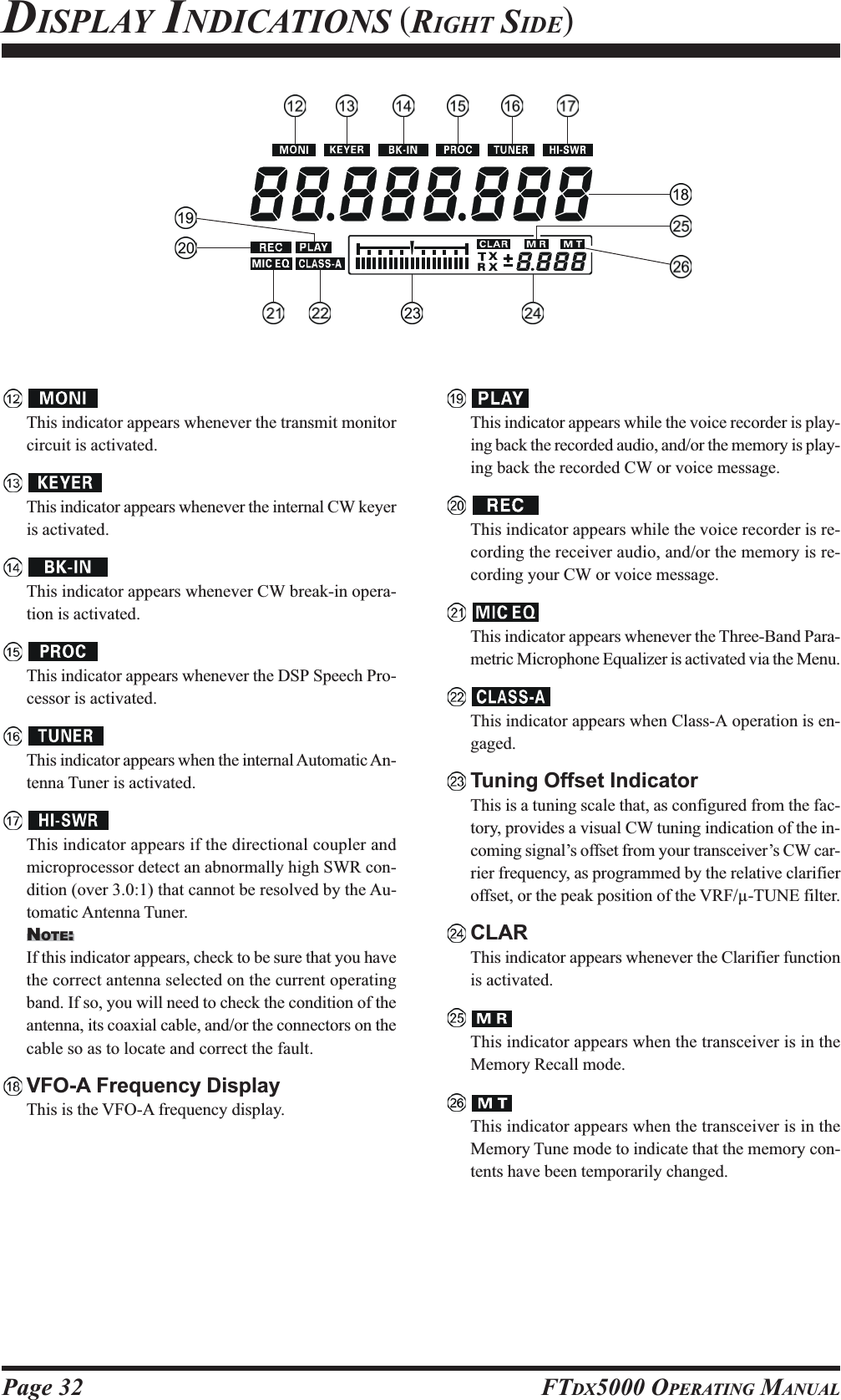
![Page 30 FTDX5000 OPERATING MANUAL(VFO-A) Block Diagram DisplayANT (1, 2, 3, 4, RX):Indicates the antenna selected for operation by the frontpanel [ANT 1-4] and [RX ANT] switches.ATT (OFF, –6 dB, –12 dB, –18 dB):Indicates the attenuation level selected for operationby the front panel [ATT] button.FLT (VRF, -TUNE, THRU):Indicates the RF filter selected for operation by thefront panel (VFO-A)[VRF/-T] button.ADVICE:The -TUNE filter is an option. The “ ” icon willnot appear when the optional -TUNE unit is not con-nected.IPO (AMP1, AMP2, IPO1, IPO2):Indicates the front end RF amplifier selected for op-eration by the front panel [IPO] button.R.FLT (300, 600, 3k, 6k, 15k):Indicates the 1st IF Roofing Filter selected for opera-tion by the front panel [R.FLT] button.ADVICE:The 300 Hz Roofing Filter is an option except the MPversion. The “300” icon will not appear when the op-tional 300 Hz Roofing Filter is not installed.AGC (AUTO, FAST, MID, SLOW):Indicates the AGC decay time selected for operationby the front panel [AGC] switch.(VFO-A) Status Indicator:This indicator appears during transmission on the VFO-A frequency.:This indicator appears whenever the VFO-A receiversquelch is open. If this indicator is not showing, andreception seems to have been lost on the VFO-A re-ceiver for no apparent reason, check the position ofthe (VFO-A)[SQL] knob and rotate it fully counter-clockwise to restore reception.:This indicator appears when the Main Tuning Dialknob’s tuning rate is selected to fast.:This indicator appears when the Main Tuning Dial knobis locked., , , , , , Displays the currently-selected operating mode for theVFO-A.This indicator appears whenever the VFO-A receiver’snarrow IF DSP filter is engaged.The “ ” icon appears when the VFO-A receiver’s(short duration) Noise Blanker is activated.The “ ” icon appears when the VFO-A receiver’s(longer-pulse) Noise Blanker is activated.DISPLAY INDICATIONS (LEFT SIDE)](https://usermanual.wiki/Yaesu-Musen/20361X60.Users-Manual-1/User-Guide-1211678-Page-17.png)
![Page 31FTDX5000 OPERATING MANUAL(VFO-B) Block Diagram DisplayANT (1, 2, 3, 4, RX):Indicates the antenna selected for operation by the frontpanel [ANT 1-4] and [RX ANT] switches.ATT (OFF, –6 dB, –12 dB, –18 dB):Indicates the attenuation level selected for operationby the front panel [ATT] button.FLT (VRF, THRU):Indicates the RF filter selected for operation by thefront panel (VFO-A)[VRF] button.ADVICE:The -TUNE filter is an option. The “ ” icon willnot appear when the optional -TUNE unit is not con-nected.IPO (AMP1, AMP2, IPO1, IPO2):Indicates the front end RF amplifier selected for op-eration by the front panel [IPO] button.R.FLT (3k, 6k, 15k):Indicates the 1st IF Roofing Filter selected for opera-tion by the front panel [R.FLT] button.AGC (AUTO, FAST, MID, SLOW):Indicates the AGC decay time selected for operationby the front panel [AGC] switch.This indicator appears whenever the Digital Noise Re-duction feature is activated.(VFO-B) Receiver S-MeterDisplays the strength of signals received on the VFO-B.(VFO-B) Status Indicator:This indicator appears during transmission on the VFO-B frequency.:This indicator appears whenever the VFO-B receiversquelch is open. If this indicator is not showing, andreception seems to have been lost on the VFO-B re-ceiver for no apparent reason, check the position ofthe (VFO-B)[SQL] knob and rotate it fully counter-clockwise to restore reception.:This indicator appears when the [CLAR(VFO-B)]knob’s tuning rate is selected to fast.:This indicator appears when the [CLAR(VFO-B)]knob is locked., , , , , , Displays the currently-selected operating mode for theVFO-B.This indicator appears whenever the VFO-B receiver’snarrow IF DSP filter is engaged.The “ ” icon appears when the VFO-B receiver’s(short duration) Noise Blanker is activated.The “ ” icon appears when the VFO-B receiver’s(longer-pulse) Noise Blanker is activated.DISPLAY INDICATIONS (LEFT SIDE)](https://usermanual.wiki/Yaesu-Musen/20361X60.Users-Manual-1/User-Guide-1211678-Page-18.png)
![Page 33FTDX5000 OPERATING MANUALREAR PANEL CONNECTIONSIF OUT JacksThis RCA output jack is used for connection to theoptional SM-5000 Station Monitor.ANT 1, 2, 3, 4 JacksConnect your main antenna(s) here, using a type-M(PL-259) plug and coaxial feedline for each. These an-tenna ports are always used for transmission, and alsoare used for reception unless a separate receive an-tenna is also used for the receiver. The internal antennatuner affects only the antenna(s) connected here, andonly during transmission.RX ANT IN JackThe BNC jack provides output of the receiver signallines from the Antenna jacks which are connected to“RX” side of the transceiver’s main T/R switching cir-cuitry.The type-M jack is for a separate receive-only antenna.An antenna connected here can be used when the [RXANT] button on the front panel is pressed.If you want to use some special kind of externalbandpass filter or preamplifier, you may connect itbetween the “RX ANT OUT” and “RX ANT IN” jacks.GNDUse this terminal to connect the transceiver to a goodearth ground, for safety and optimum performance. Usea large diameter, short braided cable for making groundconnections, and please refer to page 9 for other notesabout proper grounding.-TUNE JacksThese jacks are used for signal input/output of the op-tional RF Tuning Kit.ROTATOR JackThis 6-pin MINI-DIN Jack accepts a cable connectedto a YAESU G-800DXA/-1000DXA/-2800DXA An-tenna Rotator (listed models are current as of early2010). You may control the antenna azimuth rotation(and rotation speed) using the Function buttons on thefront panel.BAND DATA JackThis 8-pin output jack provides band selection datawhich may be used for control of optional accessoriessuch as the VL-1000 Solid-state Linear Amplifier.PACKET JackThis 5-pin input/output jack provides receiver audioand squelch signals, and accepts transmit (AFSK) au-dio and PTT control, from an external Packet TNC.Pinout is shown on page 15. The receiver audio levelat this jack is approximately 100 mVp-p (@600 Ohms).RTTY JackThis 4-pin input/output jack provides connections foran RTTY terminal unit. Pinout is shown on page 15.The receiver audio level at this jack is at a constant100-mV (@600 Ohms) level. FSK keying at this jackis accomplished by a closure of the SHIFT line toground by the terminal unit.](https://usermanual.wiki/Yaesu-Musen/20361X60.Users-Manual-1/User-Guide-1211678-Page-20.png)
![Page 34 FTDX5000 OPERATING MANUALAF OUT JackThis 3.5-mm, 3-contact jack provides dual-channellow-level receiver output, for recording or external am-plification. Peak signal level is 300 mVp-p at 10 k-Ohms. TheVFO-A receiver audio is on the left chan-nel (tip), and the VFO-B receiver audio is on the rightchannel (ring). A stereo amplifier or recorder is rec-ommended, to record each receiver’s audio separatelywhen dual reception is enabled (audio from either re-ceiver, or both, may be used via this jack). The frontpanel [AF GAIN] knobs do not affect the signals atthis jack.V-AF JackThis 3.5-mm, 3-contact jack is used for connection tothe optional SM-5000 Station Monitor.EXT SPKR JackThis 3.5-mm, 2-contact jack provides receiving audiooutput from the VFO-A and VFO-B receivers for anexternal loudspeaker or speakers, such as the SP-2000.Inserting a plug into this jack disables the internal loud-speaker. Impedance is 4 ~ 8 Ohms.E.ALC SwitchThis slide switch is used for selecting the recovery timeof the ALC.. Set this switch to “1” position when thistransceiver connects to the optional VL-1000 Solid-state Linear Amplifier.PTTJackThis RCA input jack may be used to provide manualtransmitter activation using a footswitch or otherswitching device. Its function is identical to the [MOX]button on the front panel. The same line is available atthe PACKET and RTTY jacks for TNC control. Open-circuit voltage is +13.5 VDC, and closed-circuit cur-rent is 5 mA.TRV JackThis RCA jack provides a low level RF output for usewith a transverter. Maximum output is approximately–10 dBm (0.1 mW) at 50 Ohms.EXT ALC JackThis RCA input jack accepts negative-going externalALC (Automatic Level Control) voltage from a linearamplifier, to prevent over-excitation by the transceiver.Acceptable input voltage range is 0 to –4 VDC.TX GND JackThis RCA jack’s center pin is closed to ground whilethe transceiver’s transmitter is engaged. It may be usedfor control of a peripheral device, most typically a lin-ear amplifier. To enable this jack, please set Menu item“146 tGEn ETX-GND” to the “EnA” (Enable) selec-tion.The relay circuit of this transceiver used for this jackis capable of switching AC voltage of 100 Volts at upto 300 mA, or DC voltages or 60 V at 200 mA or 30 Vat up to 1 Amp.REAR PANEL CONNECTIONS](https://usermanual.wiki/Yaesu-Musen/20361X60.Users-Manual-1/User-Guide-1211678-Page-21.png)
![Page 35FTDX5000 OPERATING MANUALREAR PANEL CONNECTIONSMIC (PATCH) JackThis RCA input jack accepts transmitter audio - eitherAFSK or voice - for transmission. This line is mixedwith the microphone audio input line, so the micro-phone should be disconnected if using this jack andmixing is not desired. The optimum impedance is 500~ 600 Ohms, and the nominal input level should be 5mV.REC JackThis RCA jack provides low-level receiver audio out-put and transmit (monitor) audio (requires the [MONI]button is turned on), for recording or external amplifi-cation. Peak signal level is 30 mVp-p at 10 k-Ohms.TX REQ JackWhen this RCA jack shorted to ground, it puts the trans-ceiver into the transmit mode, and sends out a steadyCW carrier, for linear amplifier or manual antenna tuneradjustment.+13.8 V JackThis RCA output jack provides regulated, separatelyfused 13.8 VDC at up to 200 mA, to power an externaldevice such as a packet TNC. Make sure your devicedoes not require more current (if it does, use a separatepower source).KEY JackThis 1/4-inch phone jack accepts a CW key or keyerpaddle. A 2-contact plug cannot be used in this jack.Key-up voltage is +5 V, and key-down current is 1 mA.Plug wiring is shown on page 15, and this jack may beconfigured for keyer, “Bug,” “straight key,” or com-puter keying interface operation via Menu item “056A1A R-TYPE.”Main Power SwitchThis is main power “on” (I)/“off” (O) switch of thetransceiver. Always turn this switch on before turningon the front panel’s [POWER] button.If this switch is not turned “on”, the front panel[POWER] switch will not function.Circuit Breaker SwitchThis circuit breaker shuts off in the event of danger-ously high current consumption by the transceiver.ADVICE:If the Circuit Breaker interrupts power, by all meanstry to determine the cause of the over-current condi-tion before re-applying power. To restore the CircuitBreaker after verifying that all is normal, push thisswitch in until you hear a “click.”~AC IN JackConnect the supplied 3-wire AC line cord to this socket.AC voltages of 100-240 V may be accommodated bythe transceiver any sort of modification (universal volt-age input).-TUNE JackThis 10-pin MINI-DIN jack used for control of theoptional RF Tuning Kit.DMU JackThis 8-pin MINI-DIN jack accepts a cable connectedto an optional DMU-2000 Data Management Unit.CAT JackThis 9-pin serial DB-9 jack allows external computercontrol of the transceiver. Connect a serial cable hereand to the RS-232C COM port on your personal com-puter (no external interface is required).PGM (PROGRAM) SwitchThis slide switch is used for updating the transceiver’sfirmware. The update software and instructions areavailable for download from the Vertex Standardwebsite (http://www.yaesu.com/).REMOTE JackBy plugging in the supplied FH-2 Remote Control Key-pad to this jack, direct access to the CPU of the trans-ceiver is provided for control functions such as audioplayback feature, contest memory keying, plus fre-quency and function control.](https://usermanual.wiki/Yaesu-Musen/20361X60.Users-Manual-1/User-Guide-1211678-Page-22.png)
![Page 36 FTDX5000 OPERATING MANUALFH-2 SWITCHESThe supplied Remote Control Keypad “FH-2” can be used to control the voice memory capability for the SSB/AM/FMmodes, and the contest memory keyer for the CW mode. You can also play-back up to 15 seconds of incoming receivedaudio, as well, for verification of a missed callsign or other purposes. Among the specific capabilities of the FH-2 are:On SSB/AM/FM modes, five channels of storage and playback of voice memory (20 seconds each), using your ownvoice for recording (see page ???).On CW mode, the FH-2 provides storage and recall of CW messages for repetitive CQ and contest number transmis-sions (see page ???).Play-back of the last 15 seconds of incoming receiver audio (see page ???).[1], [2], [3], [4], [5] SwitchesThese buttons work as the Voice Memory and CW Mes-sage Memory Selection Key.In the case of Voice Memory, up to 20 seconds of au-dio may be stored on each channel.For CW Messages and CW Text Messages, up to 50characters (“PARIS” specification) may be stored intoeach channel.[W], [X], [S], [T] SwitchesThese buttons are used for navigation when selectingtext characters for the programming of Contest and Textmemories.[P/B] SwitchThis button is used for playing back the last 15 sec-onds of recorded receiver audio.LOCKOFFON[LOCK] SwitchThis button may be used to lock out the FH-2’s keys,to prevent accidental activation of FH-2 operation.[MEM] SwitchThis button is pressed for the purpose of storing eithera Voice Memory or a Contest Keyer Memory channel’scontents.[DEC] SwitchWhen utilizing the sequential contest number capabil-ity of the Contest Keyer, press this button to decre-ment (back up) the current Contest Number by one digit(i.e. to back up from #198 to #197, etc.).](https://usermanual.wiki/Yaesu-Musen/20361X60.Users-Manual-1/User-Guide-1211678-Page-23.png)
![Page 37FTDX5000 OPERATING MANUALBefore turning on main power, please verify the following items once more.Have you made all ground connections securely? See page 9 for details.Do you have your antenna(s) connected to the rear-panel Antenna jack(s)? See page ?? for details.Is your microphone (and/or key or paddle) connected? See pages ?? and ?? for details.If using a linear amplifier, have all interconnections been successfully completed? See pages ?? and ?? for details.Please rotate both [AF GAIN] controls to their fully counter-clockwise positions, to avoid a loud blast of audio whenthe transceiver turns on. See page ?? for details.Rotate the [RF PWR] control fully counter-clockwise, to set minimum power at first. See page ?? for details.If your AC mains power should suffer a significant fluctuation or interruption, we recommend that you go through acomplete power-up cycle, in order to ensure that all circuits are properly initialized. To do this, be sure the front panel[POWER] switch is turned off, then set the rear panel main power switch to the “O” position. Now unplug the ACcable from the rear panel, and wait ten seconds before proceeding with the start-up procedure described on next page.BASIC OPERATION:RECEIVING ON AMATEUR BANDS3516 3433 342020](https://usermanual.wiki/Yaesu-Musen/20361X60.Users-Manual-1/User-Guide-1211678-Page-24.png)
![Page 38 FTDX5000 OPERATING MANUALMain Tuning Dial knob[ANTENNA] Buttons [BAND] Buttons(VFO-B)[SQL] Knob[BAND/MHz] Button[FAST] Button[CLAR(VFO-B)] Knob1. Plug the AC cable back in, set the rearpanel main power switch to “I” posi-tion.2. Press and hold in the front panel[POWER] switch for one second to turnthe transceiver on.3. The transceiver will start up on 7.000.00MHz LSB, and normal operation may begin.NOTE:To turn power off, press and hold in the front panel[POWER] switch for one second.4. Rotate the (VFO-A)[AF GAIN]knob to set a comfortable audio levelon incoming signals or noise. Clock-wise rotation of the (VFO-A)[AFGAIN] knob increases the volumelevel.NOTE:When using headphones, start by rotating the (VFO-A)[AF GAIN] knob counter-clockwise, then bring thevolume level up after you put the headphones on. Thiswill minimize the chance of damage to your hearingcaused by an unexpectedly-high audio level.5. Press the (VFO-A)[RX]button to engage the VFO-A receiver; the imbeddedLED will glow green.ADVICE:::::If you press the (VFO-A)[RX] button when the imbedded LED is alreadyglowing green, the LED will now blinks; this indi-cates that the VFO-A receiver is temporarily muted.Just press the (VFO-A) [RX] button once more torestore VFO-A receiver operation.Press the (VFO-B)[RX] button toengage Dual Reception (using theVFO-B receiver in addition to theVFO-A receiver). When you pressthe (VFO-B)[RX] button, its imbed-ded LED will glow green; press-ing this button once more willturn off the VFO-B receiver, andthe imbeded LED will go dark.Use the VFO-B receiver’s (VFO-B)[AF GAIN] knob to adjust theVFO-B receiver volume level.6. Press the [BAND] buttoncorresponding to the Ama-teur band on which you wishto begin operation.ADVICE:::::One-touch selection ofeach Amateur band be-tween 1.8 and 50 MHz is provided.The FTDX5000 utilizes a triple band-stack VFOselection technique, which permits you to store upto three favorite frequencies and modes onto eachband’s VFO register. For example, you may storeone frequency each on 14 MHz CW, RTTY, andUSB, then recall these VFOs by successive, mo-mentary presses of the [14] MHz band button. EachAmateur band button may similarly have up to threefrequency/mode settings applied.[POWER] Switch(VFO-A)[RX] ButtonBASIC OPERATION:RECEIVING ON AMATEUR BANDSHere is the typical start-up procedure for normal operation:(VFO-A)[SQL] Knob [MODE] Buttons(VFO-B)[AF GAIN] Knob(VFO-A)[AF GAIN] Knob[(T)DOWN] /[(S)UP] Buttons(VFO-B)[RX] Button](https://usermanual.wiki/Yaesu-Musen/20361X60.Users-Manual-1/User-Guide-1211678-Page-25.png)
![Page 39FTDX5000 OPERATING MANUALIf you press the[BAND/MCH] but-ton briefly, the im-bedded LED of the[BAND/MCH] but-ton glows red, and the[CLAR(VFO-B)]knob may be used asa band selectionknob.7. Press the [T(DOWN)]/[S(UP)] buttons to tune theVFO-A frequency in 1 MHzstep.ADVICE:::::You may change the tuning step to 100 kHz via theMenu item “140 TUN MHz SEL”. See page 127.8. Move the [ANT 1-4] button up and down to select theappropriate antenna for the band in use; alternatively,if one is connected, you may also press the [RX ANT]button. Up to four TX/RX anten-nas may be connected, or one RX-only antenna.ADVICE:::::Once you have made your antenna selection, that an-tenna is “remembered” by the microprocessor in con-junction with the VFO register (frequency and mode)in use when you chose that particular antenna.9. Press the appropriate [MODE]button to select the desired op-erating mode.ADVICE:::::By convention in the Ama-teur bands, LSB is used onthe 7 MHz and lower bands(with the exception of 60 meters), while USB isutilized on the 14 MHz and higher bands.When changing modes from SSB to CW, you willobserve a frequency shift on the display. This shiftrepresents the BFO offset between the “zero beat”frequency and the audible CW pitch (tone) you canhear (the pitch is programmed by the [PITCH]knob), even though the actual tone that you hear isnot changing. If you do not want this frequency shiftto appear when changing modes from (for example)USB to CW, use the Menu item “063 A1AFRQDISP,” described on page 122.When operating on the FM modein the VFO-A, rotate the (VFO-A)[SQL] (Squelch) knob clock-wise just to the point where thebackground noise is just silenced.This is the point of maximum sensitivity to weaksignals. Excessive advancement ofthe Squelch knob will degrade theability of the receiver to detectweak signals. Adjustment of theVFO-B Squelch is accomplishedusing the (VFO-B)[SQL] knob.10.Rotate the Main Tuning Dial knob to tune around theband, and begin normal operation.ADVICE:::::Clockwise rotation of the Main Tuning Dial knobincreases the operating frequency, one “step” of thesynthesizer at a time; similarly, counter-clockwiserotation of the Main Tuning Dial knob will decreasethe frequency.Two steps, one “normal”and one “fast,” are avail-able on each operatingmode. Pressing the[FAST] button engagesthe “Fast” tuning selec-tion.BASIC OPERATION:RECEIVING ON AMATEUR BANDSOPERATING MODE 1 STEP 1 DIAL ROTATIONLSB, USB, CW, 10Hz 10kHzRTTY, PKT(LSB)[100Hz][100kHz]AM, FM, PKT(FM)100Hz [1kHz]100kHz [1MHz][ ] : [FAST] switch set to “ON”It is possible to separate the frequency change overone dial rotation, only while operating solely onthe CW mode, using the Menu items “138 TUNDIAL STP”, and “139 TUN CW FINE”. See page127.If you want to navigate quickly, so as to effect rapidfrequency change, there are several techniquesavailable:yDirect keyboard entry of the frequency (see page49).yUse the microphone’s [UP]/[DWN] scanningkeys, if your microphone is so equipped (seepage 49).](https://usermanual.wiki/Yaesu-Musen/20361X60.Users-Manual-1/User-Guide-1211678-Page-26.png)
![Page 40 FTDX5000 OPERATING MANUALBASIC OPERATION:RECEIVING ON AMATEUR BANDSCLAR (CLARIFIER) OPERATION ON VFO-AThe [RX CLAR/FAST], [CLEAR], [TX CLAR/LOCK] buttons and [CLAR(VFO-B)] knob are used to offset either thereceive, transmit, or both frequencies from their settings on the VFO-A frequency (the Clarifier does not affect the VFO-B,however). The four small numbers on the LCD display show the current Clarifier offset. The Clarifier controls on theFTDX5000 are designed to allow you to preset an offset (up to ±9.999 kHz; frequency step depends on the Main TuningDial knob) without actually retuning, and then to activate it via the Clarifier’s [RX CLAR/FAST] and [TX CLAR/LOCK]buttons. This feature is ideal for following a drifting station, or for setting small frequency offsets sometimes utilized in DX“Split” work.Here is the technique for utilizing the Clarifier:1. Press the [RX CLAR/FAST] button. The “ ” and“” icon will appear in the display, and the pro-grammed offset will be applied tothe receive frequency.ADVICE:::::If the “ ” and “ ” icon does not appear, checkto see if the LED imbedded in the [A/B] button glowsorange. If so, pressing the [A/B] button will cause theLED imbedded in the [A/B] button to go out. Now,press the [RX CLAR/FAST] button to begin clarifieroperation.2. Rotation of the [CLAR(VFO-B)] knob will allow youto modify your initial offset on thefly. Offsets of up to ±9.999 kHzmay be set using the Clarifier.To cancel Clarifier operation, press the [RX CLAR/FAST]button. The “ ” and “ ” icon will disappear fromthe display.ADVICE:Turning the clarifier “off” simply cancels the applicationof the programmed offset from the receive and/or transmitfrequencies. To clear out the programmed clarifier offsetaltogether, and reset it to “zero,” press the [CLEAR] but-ton.TX CLARWithout changing the receive frequency, you mayalternatively apply the Clarifier offset to the trans-mit frequency (typically, for “split” DX pile-ups).See page 79 for details.The Tuning Offset Indicator provides a graphical representation of the Clarifier offset.On CW mode, the Tuning Offset Indicator is used for CW Center Tuning, instead of Clarifier Offset, as the trans-ceiver is configured at the factory. If you wish to change this, so that the Clarifier Offset is also displayed on CW, usethe following procedure:1. Press the [MENU] button to enter the Menu mode.2. Rotate the (VFO-A)[SELECT] knob to selectMenu item “010 DISP BAR SEL”.3. Rotate the (VFO-B)[SELECT] knob to select“CLARCLARCLARCLARCLAR (Clarifier)” (replacing the default “CWCWCWCWCWTUNETUNETUNETUNETUNE (CW TUNING)”selection).4. Press and hold in the[MENU] button for twoseconds to save the newsetting and exit to nor-mal operation.[CLAR(VFO-B)] Knob[RX CLAR/FAST] Button[CLEAR] Button[A/B] Button[Plus (+) Offset][Zero Offset](Minus (–) Offset)(VFO-B)[SELECT] Knob[MENU] Button(VFO-A)[SELECT] Knob](https://usermanual.wiki/Yaesu-Musen/20361X60.Users-Manual-1/User-Guide-1211678-Page-27.png)
![Page 41FTDX5000 OPERATING MANUALLOCKYou may lock the setting of the Main Tuning Dial knob, to prevent accidental frequency change.To lock out the Main Tuning Dial knob, just press the[LOCK] button that is located to the right of the MainTuning Dial knob. To unlock the Dial setting, and restorenormal tuning, just press the [LOCK] button once more.When the Main Tuning Dial knob is “locked”, the blue“” icon will appear on the display.DIMThe illumination level of the analog meter and frequency display may be reduced, if you are using the transceiver in a darkenvironment where high brightness is not desired.To reduce the illumination level, press the [DIM] button,located to the left of the analog meter. To restore full bright-ness, press the [DIM] button once more.ADVICE:You may also customize the amount of brightness reduc-tion engaged by the pressing of the [DIM] button, and mayuse different brightness levels for different front panel ar-eas. Menu item “008 DISP DIM MTR” adjusts the bright-ness level of the analog meter; while menu item “009 DISPDIM VFD” sets the brightness levels of the frequency dis-play (these settings are effective only when the [DIM] but-ton is pressed).[LOCK] Button[LOCK] ButtonOPERATION ON 60-METER (5 MHZ) BAND (U.S. VERSION ONLY)The recently-released 60-meter band is covered, in the FTDX5000, by five special, fixed memory channels. These channels areset to USB, and they appear between the “last” PMS channel (“P-9UP-9UP-9UP-9UP-9U”) and the first “regular” memory channel (Channel 1).To operate on the 60-meter (5 MHz) band:1. Press the [V/M] button once, if neccessary, to enter the“Memory” mode (the “ ” icon will appear on thedisplay.2. Press and hold in the [BAND/MCH] button for twoseconds. The LED imbedded in the button will glowyellow to signify that rotation of the [CLAR(VFO-B)]knob will allow selection the memory channel.3. Memory channels “US-1US-1US-1US-1US-1” through “US-5US-5US-5US-5US-5” are pre-pro-grammed, at the factory, with the permitted frequen-cies in the 5 MHz band, and the USB mode is auto-matically selected on these channels.4. To exit from 60-meter operation and return to the VFOmode, just press the [V/M] button.NOTE:The frequencies and operating mode for 5 MHz band op-eration are both fixed, and may not be changed.[CLAR(VFO-B)] Knob[V/M] Button[BAND/MCH] ButtonCHANNEL NUMBERUS-1US-2US-3US-4US-5FREQUENCY5.3320 MHz5,3480 MHz5.3680 MHz5.3730 MHz5.4050 MHzBASIC OPERATION:RECEIVING ON AMATEUR BANDS](https://usermanual.wiki/Yaesu-Musen/20361X60.Users-Manual-1/User-Guide-1211678-Page-28.png)
![Page 42 FTDX5000 OPERATING MANUALQUICK POINT:By convention in the amateur bands, LSB is used on the 7MHz and lower bands (with the exception of 60 meters),while USB is utilized on the 14 MHz and higher bands.ADVICE:When operating in Dual Receive, the manner in whichthe audio is fed to the left and right sides of your head-phones (Stereo, Monaural, or Mixed) may be config-ured using Menu item “104 ROUT HEADPHN” (seepage 124).When changing modes from SSB to CW, you will ob-serve a frequency shift on the display. This shift repre-sents the BFO offset between the “zero beat” frequencyand the audible CW pitch (tone) you can hear (the pitchis programmed by the [PITCH] knob), even thoughthe actual tone that you hear is not changing. If you donot want this frequency shift to appear when changingmodes from (for example) USB to CW, use the Menuitem “062 A1A FRQ DISP”, described on page 122.When operating on the FM mode on the VFO-B re-ceiver, rotate the (VFO-B)[SQL] knob clockwise justto the point where the background noise is just silenced.This is the point of maximum sensitivity to weak sig-nals. Excessive advancement of the (VFO-B)[SQL]knob will degrade the ability of the receiver to detectweak signals. Adjustment of the VFO-A squelch is ac-complished using the (VFO-A)[SQL] knob.DUAL RECEIVEThe FTDX5000 is capable of simultaneous reception on the same amateur band, using the VFO-A and VFO-B receivers,in what is called the “Dual Receive” mode. Especially useful for DX work, here is the operating procedure for Dual Receiveoperation.CONVENIENCE FEATURES1. While receiving on the VFO-A, engage the VFO-Breceiver by pressing the (VFO-B)[RX] button, locatedto the upper left of the [CLAR(VFO-B)] knob. Youwill now be receiving on the two frequencies shownon the LCD display (for VFO-A) and SUB DISPLAY-I (for VFO-B).2. Adjusting the volume:To adjust the VFO-A audio level, rotate the (VFO-A)[AF GAIN] knob. To adjust the VFO-B audio level,rotate the (VFO-B)[AF GAIN] knob. In both cases,clockwise rotation of the knob will increase the vol-ume level.3. Press the [B] button, located to the upper left of theMain Tuning Dial knob. An orange LED imbedded inthe [B] button, and you may now change the operatingmode of the VFO-B receiver by pressing the appropri-ate [MODE] selection button.4. You may also press the [BAND] buttons to select theoperating band on which you want to set up the VFO-B receiver.5. To return the mode and band selections to VFO-A, pressthe [A] button, located to the left of the [B] button. Ared LED imbedded in the [A] button, and you may nowchange the operating mode and band of the VFO-Areceiver.6. Rotate the Main Tuning Dial knob to adjust the MainVFO-A frequency, and rotate the [CLAR(VFO-B)]knob to adjust the VFO-B frequency.ADVICE:::::If the VFO-B frequency does not change, check to seeif the orange LED imbedded in the [A/B] button doesnot light up. If so, pressing the [A/B] button will causethe LED imbedded in the [A/B] button glows orange.Now, rotate the [CLAR(VFO-B)] knob to begin toadjust the VFO-B frequency.7. To cancel Dual Receive operation, and receive just onthe VFO-A receiver, press the (VFO-B)[RX] button;the imbedded green LED will go out, and monobandoperation on the VFO-A receiver will resume.NOTE:::::Please remember that, while the [B] button glows orange,any mode or band changes will still be applied to the VFO-B receiver, whether or not Dual Receive is engaged.[CLAR(VFO-B)] Knob[A/B] Button[BAND] Buttons[MODE] ButtonsSUB DISPLAY-I(VFO-B)[RX] Button[A] / [B] Buttons(VFO-A)[SQL] Knob(VFO-B)[SQL] Knob(VFO-A)[AF GAIN] Knob(VFO-B)[AF GAIN] Knob](https://usermanual.wiki/Yaesu-Musen/20361X60.Users-Manual-1/User-Guide-1211678-Page-29.png)
![Page 43FTDX5000 OPERATING MANUALCONVENIENCE FEATURESDUAL RECEIVEUsing Headphones for Dual ReceiveTo take advantage of dual reception, you will want to con-nect stereo headphones to the PHONES jack. Like theAF GAIN control, headphone audio mixing can also beconfigured as desired from Menu item “104 ROUTHEADPHN”. Three audio mixing schemes are selectableas follows:SEPARETESEPARETESEPARETESEPARETESEPARETE: Audio from the VFO-A receiver is heard onlyin the left ear, and VFO-B receiver audiosolely in the right ear.CONBINE1CONBINE1CONBINE1CONBINE1CONBINE1: Audio from both VFO-A and VFO-B receiv-ers can be heard in both ears, but VFO-Baudio is attenuated in the left ear and VFO-A audio is attenuated in the right ear.CONBINE2CONBINE2CONBINE2CONBINE2CONBINE2: Audio from both VFO-A and VFO-B receiv-ers are combined and heard equally in bothears (“Monaural” mode).Sideband Diversity ReceptionHere you receive a single AM signal through the two re-ceivers, each receiving the opposite sideband. Skywave-propagated signals often show phase distortion in thismode, but it gives you a view of the entire passband, fromwhich you can then select the best sideband for listening(or for SWL Dx’ing, you may want to listen to both side-bands at the same time, to get the best copy). Ongroundwave signals, where the phase of the sidebands islikely to be the same, there is an interesting sense of depthto the signal.To tune in a signal using this mode, you should have ste-reo headphones connected to the front panel PHONESjack.Set the VFO-A to either LSB or USB mode, and tunefor zero beat on the desired signal.Press the [AXXXXXB] button to copy this mode and fre-quency into the VFO-B, then press the [MODE] but-ton to select the opposite sideband for the VFO-A.If using headphones, set the headphone mixing schemeto the “CONBINE1CONBINE1CONBINE1CONBINE1CONBINE1” mode via the Menu item “104ROUT HEADPHN”, and activate dual reception.Adjust the [AF GAIN] knob(s) to balance the volumeof the two receivers.If interference is present on one of the channels, youmay have to turn its [AF GAIN] knob to suppress thatchannel (or press the green [RX] button to disable thereceiver with the sideband experiencing interference).Otherwise, try changing the headphone audio mixingscheme to “CONBINE2CONBINE2CONBINE2CONBINE2CONBINE2” or “SEPARETESEPARETESEPARETESEPARETESEPARETE” in the Menuitem “104 ROUT HEADPHN”, for different effects(or try settings with similar effects on your externalamplifier). Although you don’t get the “stereophonic”effect in the monaural mode, the two signals are stillmixed, offering the potential for much better copy thanin regular AM or even single-sideband ECSS modes.](https://usermanual.wiki/Yaesu-Musen/20361X60.Users-Manual-1/User-Guide-1211678-Page-30.png)
![Page 44 FTDX5000 OPERATING MANUALBandwidth Diversity ReceptionThis mode involves receiving the same signal through twodifferent bandpass filters. The frequency and mode of boththe VFO-A and VFO-B are the same. The VFO-A can beset up for a wide bandpass, using the [WIDTH] knobs,and the VFO-B for a narrow bandpass, resulting in a spa-tial perception of the channel. Although any mode (exceptFM) can be used, CW offers the widest array of choices,and perhaps the most startling effects on crowded chan-nels.Stereo headphones or an external stereo speaker are rec-ommended for this mode. To set up the transceiver forbandwidth diversity reception:Select the desired mode on the VFO-A.Tune to the signal of interest.Press the [AXXXXXB] button to copy this mode and fre-quency into the VFO-B.If using headphones, set the headphone mixing schemeto the “CONBINE1CONBINE1CONBINE1CONBINE1CONBINE1” mode via the Menu item “104ROUT HEADPHN”, and activate dual reception.Adjust the [AF GAIN] knob(s) to balance the volumeof the two receivers.Now try manipulating the [SHIFT] and [WIDTH]knobs to observe the interesting effects of bandwidthdiversity.CONVENIENCE FEATURESDUAL RECEIVEPolarity DiversitySimilar in concept to the bandwidth diversity ca-pability just described, another interesting capabil-ity of the FTDX5000 is the ability to use two differ-ent antennas on the same frequency, using dual re-ception. For example, you might have a horizontalYagi on the main band, and a vertical antenna onthe sub band, then lock the two frequencies togetherand engage dual reception.Frequently, the fading observed on the HF bands isnot so much a change in ionization level, but rathera shift in the polarization of the signal as it travelsto and from the ionosphere. Having an opposite-polarization antenna available can fill in the signalduring deep fades, and you may then transmit onwhichever antenna is providing the strongest sig-nal at the moment (see the discussion below on SplitFrequency operation).](https://usermanual.wiki/Yaesu-Musen/20361X60.Users-Manual-1/User-Guide-1211678-Page-31.png)
![Page 45FTDX5000 OPERATING MANUALCONVENIENCE FEATURESP.BACK (AUDIO PLAYBACK) FROM MAIN (VFO-A) RECEIVEROnce engaged by the operator, the FTDX5000 begins the automatic recording of the last 15 seconds of incoming receiveraudio on the VFO-A by plugging in the supplied FH-2 Remote Control Keypad into the rear panel’s REMOTE jack. Thiscapability is especially useful for confirming a callsign that may have been difficult to copy due to noise or QRM, etc.RecordingPress and hold in the FH-2’s [P/B] key for two sec-onds to initiate recording. The “ ” icon will ap-pear in the display to confirm that recording is inprogress.Press the FH-2’s [P/B] key momentarily to halt re-cording; the “ ” icon will go out.LOCKOFFONPlaybackPress the FH-2’s [P/B] key briefly, after recording hasbeen halted, to begin playback of the recorded audio;the “ ” icon will appear in the display to confirmthat playback is in progress. The last 15 seconds ofaudio will be heard in the speaker or headphones. Ifyou do not intervene, the entire 15 seconds will beplayed back endlessly.To halt playback at any time, just press the [P/B] keybriefly again. The next time you press the [P/B] key, itwill pick up the playback where you left off.ADVICEYou may adjust the playback level of the recording by themain [AF GAIN] knob.StartStop15 Seconds](https://usermanual.wiki/Yaesu-Musen/20361X60.Users-Manual-1/User-Guide-1211678-Page-32.png)
![Page 46 FTDX5000 OPERATING MANUAL“MY BANDS” OPERATIONWhen operating on an amateur band, it is possible to use the [BAND] buttons to engage the use of the [CLAR(VFO-B)]knob for amateur band selection. The “My Bands” feature allows you to select several amateur bands, and make only thosebands available for selection via the [CLAR(VFO-B)] knob.This feature can be very useful in a contest, where the 10/18/24 MHz band are not used, or if you do not have antennas forsome bands.“My Bands” Setup1. Press the [MENU] button to engage the Menu mode.2. Rotate the (VFO-A)[SELECT] knob to select Menuitem “144 TUN MY BAND.”3. Rotate the (VFO-B)[SELECT] knob to choose a bandthat you wish to skip (omit) from the band-selectionloop (when using the [CLAR(VFO-B)] knob for bandselection). The available choices are 1.8M/3.5M/7M/10M/14M/18M/21M/24M/28M/50M/GEN(GeneralBand)/T14M(Transverter “1”)/T28M(Transverter“2”)/T50M(Transverter “3”).4. Press the [ENT] button (one of the [BAND] button) toset the selected band to “skipped”. The “ONONONONON” notationat the right of the band notation will change to “OFFOFFOFFOFFOFF”.5. Repeat steps 3 and 4 to select (“ONONONONON”) /deselect (“OFFOFFOFFOFFOFF”)as many bands as you like.6. Press and hold in the [MENU] button for two secondsto lock in the new configuration and exit to normaloperation.ADVICE:The “My Band” feature affects only VFO-A band.CONVENIENCE FEATURES“My Band” Operation1. Press the [V/M] button once, if neccessary, to enter the“VFO” mode.2. Press the [BAND/MCH] button briefly; the imbeddedLED will glow Red.3. Rotate the [CLAR(VFO-B)] knob knob to choose theamateur band on which you wish to operate. Only thoseamateur bands that have not been skipped will appearas you scroll through the bands.(VFO-B)[SELECT] Knob[MENU] Button(VFO-A)[SELECT] Knob[CLAR(VFO-B)] Knob[V/M] Button[BAND/MCH] Button14 MHz14 MHz18 MHz50 MHz21 MHz21 MHz7 MHz7 MHz5 MHz1.8 MHz28 MHz28 MHz24 MHz3.5 MHz3.5 MHz10 MHz14 MHz 21 MHz7 MHz28 MHz3.5 MHz](https://usermanual.wiki/Yaesu-Musen/20361X60.Users-Manual-1/User-Guide-1211678-Page-33.png)
![Page 47FTDX5000 OPERATING MANUALCONVENIENCE FEATURESBAND STACK OPERATIONThe FTDX5000 utilizes a triple band-stack VFO selection technique, that permits you to store up to three favorite frequen-cies and modes onto each band’s VFO register. For example, you may store one frequency each on 14 MHz CW, RTTY, andUSB, then recall these VFOs by successive, momentary presses of the [14] MHz band button. Each Amateur band key maysimilarly have up to three frequency/mode settings applied. Both the VFO-A and VFO-B systems have their own, indepen-dent, band stacks.A typical setup, for the 14 MHz band, might be arrangedlike this:1. Program 14.025 MHz, CW Mode, then press the [14]MHz band button;2. Program 14.080 MHz, RTTY Mode, then press the [14]MHz band button;3. Program 14.195 MHz, SSB Mode, then press the [14]MHz band button.With this configuration, successive momentary presses ofthe [14] MHz band button will allow you to toggle se-quentially through these three VFOs.C.S (CUSTOM SWITCH)An often-used Menu mode selection may be brought out to the front panel’s [C.S] button.C.S Setup1. Press the [MENU] button to engage the Menu mode;the Menu list will appear on the SUB DISPLAYs.2. Rotate the (VFO-A)[SELECT] knob to select theMenu item you want to be able to access via the [C.S]button.3. Press and hold in the [C.S] button for two seconds tolock in your selection.4. Press and hold in the [MENU] button for two secondsto save the new configuration and exit to normal op-eration.Menu Selection Recall via [C.S] button1. Press the [C.S] button. The programmed Menu itemwill appear on the display.2. You may now rotate the (VFO-B)[SELECT] knob tochange the setting of this menu item.3. Press the [MENU] button for two seconds, when youare done, to save the new configuration and exit tonormal operation.USBRTTYCW(VFO-A)[SELECT] Knob[MENU] Button[C.S] Button(VFO-B)[SELECT] Knob[MENU] Button[C.S] Button[BAND] Button](https://usermanual.wiki/Yaesu-Musen/20361X60.Users-Manual-1/User-Guide-1211678-Page-34.png)
![Page 48 FTDX5000 OPERATING MANUALROTATOR CONTROL FUNCTIONSWhen using a YAESU model G-800DXA, G-1000DXA, or G-2800DXA rotator (not supplied), it is possible to control itfrom the front panel of the FT-2000D.1 Press and hold in the [ENT] button (one of the [BAND]button) for two seconds. The SUB DISPLAYs willchange over to the “Rotator Control” configuration.2 Press either the [3.5(2)] button or the [7.0(3)] buttonto rotate the antenna. Pressing the [3.5(2)] button willcause rotation to the left (counter-clockwise), whilepressing the [7.0(3)] button will cause rotation to theright (clockwise).3 Press the [14(5)] button or the [18(6)] button to con-trol the speed of rotation. Pressing the [14(5)] buttonwill cause slower rotation, while pressing the [18(6)]button will speed up rotation. Usually, you will be us-ing the “100%” setting.When you are through exercising rotator control, press the[ENT] button briefly. The SUB DISPLAYs will return tothe normal display.CONVENIENCE FEATURESIMPORTANT NOTESet to match the starting point of your rotatorcontrol indicator needle via the Menu item “012DISP RTR STU.” The default setting is zero(north). If your controller starting point is south,the Menu item “012 DISP RTR STU” must beset to “180°180°180°180°180°.” If not set properly the FTDX5000display will not show the correct direction.When the rotator control indicator needle doesnot indicate the precise antenna direction, ad-justs the indicator needle precisely to the an-tenna direction via the Menu item “013 DISPRTR ADJ.”[ENT] Button[3.5(2)], [7(3)] Button[14(5)], [18(6)] ButtonANT 1~AC INANT 2EXT CONTROLREMOTECONTROLROTEXTCONTROLSELECTSWITCHPRESETADJOPERATIONMODEADJ. MODE FULLSCALEADJOVERLAPLED ADJOUT VOLADJABOPTIONAL CONNECTION CABLE ()T9101556Counter-clockwise Rotation Clockwise RotationSpeed Down Speed Up](https://usermanual.wiki/Yaesu-Musen/20361X60.Users-Manual-1/User-Guide-1211678-Page-35.png)
![Page 49FTDX5000 OPERATING MANUALMORE FREQUENCY NAVIGATION TECHNIQUESKeyboard Frequency EntryYou may enter operating frequencies, for either the VFO-A or VFO-B bands, using the front panel band/frequencyselection keys.Example 1: Enter 14.250.000 MHz into the VFO-A1. Press the [ENT] button to engage the direct frequencyentry process. Now, be-ginning with the “10MHz” digit of the fre-quency (the leftmostdigit), we will enter therequired digits of the fre-quency.2. Press, in order, the digits of the operating frequency,using the [BAND] buttons (which have the frequency-entry digit or decimal point on the right side of theslash bar). In this example, enter[1.8/1] Æ [10/4] Æ[GEN/.] Æ [3.5/2] Æ[14/5] Æ [50/0] Æ [50/0] Æ [50/0] Æ [50/0]The decimal point after the “MHz” portion of the fre-quency must be entered, but no decimal point is re-quired after the “kHz” portion.3. Press the [ENT] button once more. A short “beep” willconfirm that the frequency entry was successful, andthe new operating frequency will appear on the Main(VFO-A) frequency display fields.Example 2: Enter 7.100.000 MHz into the VFO-B1. Press the [B] button, lo-cated to the upper left ofthe Main Tuning Dialknob. The imbeddedLED in the [B] button isglows orange.2. Press the [ENT] button to engage the direct frequencyentry process. Now, beginning with the “10 MHz” digitof the frequency (the leftmost digit), we will enter therequired digits of the frequency to be entered into theVFO-B register.3. Press, in order, the digits of the operating frequency,using the [BAND] buttons (which have the frequency-entry digit or decimal point on the right side of theslash bar). In this example, enter[21/7] Æ [GEN/.] Æ [1.8/1] Æ[50/0] Æ [50/0] Æ [50/0] Æ [50/0] Æ [50/0]4. Press the [ENT] button once more. A short “beep” willconfirm that the frequency entry was successful, andthe new operating frequency will appear on the VFO-B frequency display fields.ADVICE:If you attempt to enter a frequency outside the operat-ing range of 30 kHz ~ 60 MHz, the microprocessorwill ignore the attempt, and you will be returned toyour previous operating frequency. If this happens,please try again, taking care not to repeat the error inthe frequency entry process.Using the [T(DOWN)]/[S(UP)] ButtonsPress the [T(DOWN)]/[S(UP)] button to tune theVFO-A frequency in 1 MHzstep.Press the [B] button first (The imbedded LED in the[B] button is glows orange), then press the[T(DOWN)]/[S(UP)] button to tune the VFO-B fre-quency in 1 MHz step.ADVICE:::::You may change the tuning step of the [T(DOWN)]/[S(UP)] button to 100 kHz via the Menu item “140 TUNMHz SEL”. See page 127.Using the [UP]/[DWN] Switches of the Supplied MH-31B8 Hand MicrophoneThe [UP]/[DWN] switches on the supplied MH-31B8 HandMicrophone may also be used for manually scanning up-ward or downward in frequency, respectively.The microphone’s [UP]/[DWN]switches utilize the tuning stepsof the Main Tuning Dial knob;moreover, when the microphone’s[FAST] key is pressed, the tuningrate increases by a factor of ten, ina manner similar to the effect of thetransceiver’s front-panel [FAST]button.ADVICE:In the AM and FM modes, you may in-dependently set the tuning steps whenusing the [UP]/[DWN] switches. To setnew tuning steps, use Menu items “141TUN AM STEP” and “142 TUN FM STEP”.CONVENIENCE FEATURESDYNAMIC MICROPHONEMH-31DWN FST UP[DWN] Button[FST] Button[UP] Button](https://usermanual.wiki/Yaesu-Musen/20361X60.Users-Manual-1/User-Guide-1211678-Page-36.png)
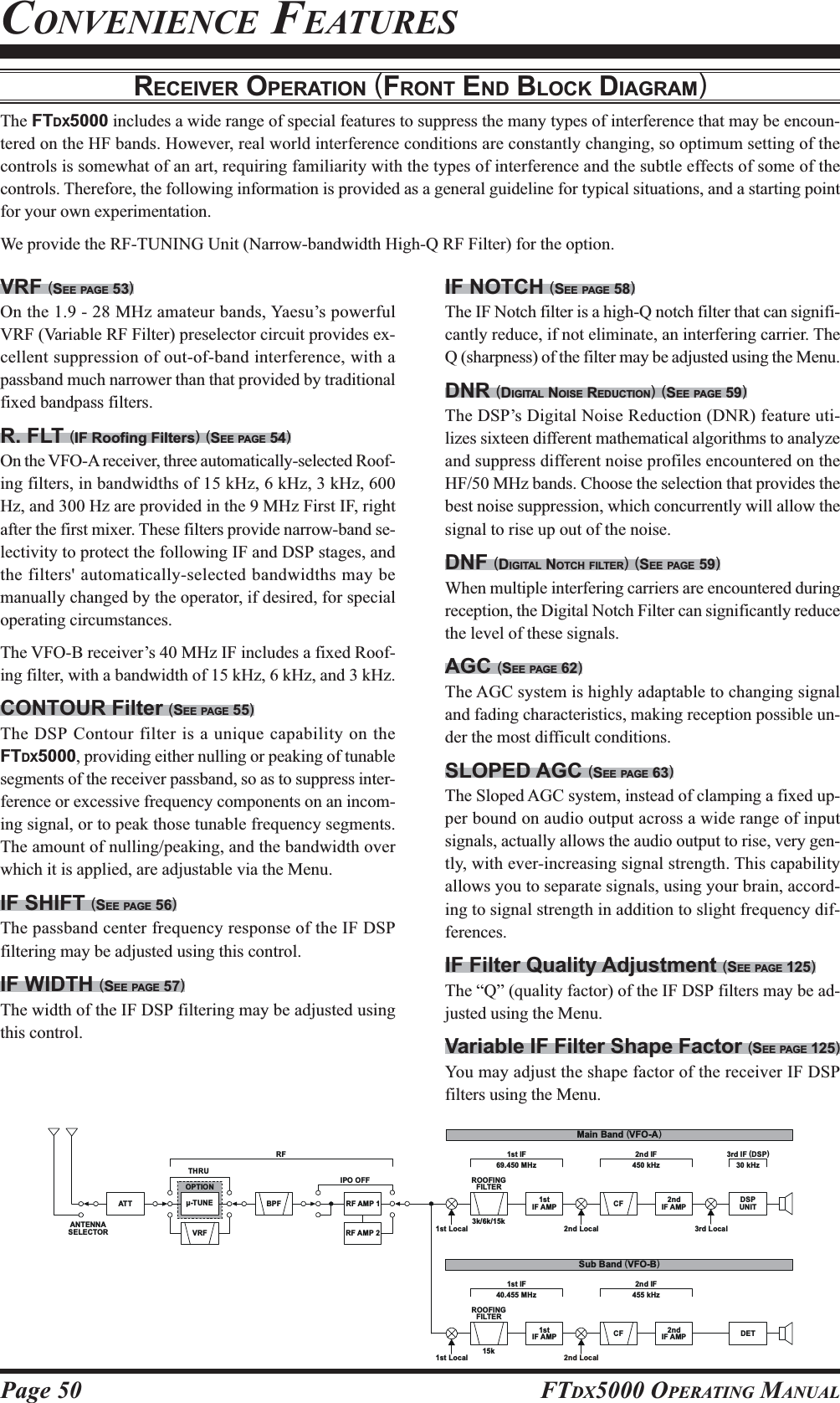
![Page 51FTDX5000 OPERATING MANUALIPO (INTERCEPT POINT OPTIMIZATION)The IPO feature allows the operator to optimize the characteristics of the receiver front end, depending on the current noiselevel and the strength of incoming signals.VFO-A IPO SetupPress the [A] button (the imbedded LED in the [A]button is glows red), if desired.Move the [IPO] knob up and down to set the desiredcharacteristic of the VFO-A receiver front end, per thechart below.AMP1AMP1AMP1AMP1AMP1: Amplifies the incoming signal path using alow distortion RF preamplifier (normally, theIPO selection is set to this position).AMP2AMP2AMP2AMP2AMP2: Increases the sensitivity.IPO1IPO1IPO1IPO1IPO1: Improves the IPO.IPO2IPO2IPO2IPO2IPO2: Bypasses the RF preamplifier, yielding di-rect feed to the first mixer. As a result, theIPO is improved more.The selected receiver RF preamplifier will be indicatedin the IPO column of the Block Diagram Display onthe display.CONVENIENCE FEATURESVFO-B IPO SetupPress the [B] button (the imbedded LED in the [B]button is glows orange).Move the [IPO] knob up and down to set the desiredcharacteristic of the VFO-B receiver front end, per thechart below.AMP1AMP1AMP1AMP1AMP1: Amplifies the incoming signal path using alow distortion RF preamplifier (normally, theIPO selection is set to this position).AMP2AMP2AMP2AMP2AMP2: Increases the sensitivity.IPO1IPO1IPO1IPO1IPO1: Improves the IPO.The selected receiver RF preamplifier will be indicatedin the IPO column of the Block Diagram Display onthe display.ADVICE:On the 10 MHz and lower bands, it generally is not necessary to use any preamplifier at all; selecting the “ONONONONON” positiondescribed above will increase the strong-signal-handling capability of the receiver, and generally will result in more pleas-ant reception due to reduced noise. If you can hear band noise with the preamplifiers disengaged, then a preamplifier isgenerally not needed.[A] Button[IPO] Knob [B] Button[IPO] KnobPress the [IPO] knob briefly to select the IPO settingto “AMP1” for quick selection.Press the [IPO] knob briefly to select the IPO settingto “AMP1” for quick selection.](https://usermanual.wiki/Yaesu-Musen/20361X60.Users-Manual-1/User-Guide-1211678-Page-38.png)
![Page 52 FTDX5000 OPERATING MANUALATTEven with the IPO function on, extremely strong local signals or high noise can still degrade reception. In such situations,you can use the [ATT] button to insert 6, 12, or 18-dB of RF attenuation in front of the RF amplifier.VFO-A IPO SetupPress the [A] button (the imbedded LED in the [A]button is glows red), if desired.Move the [ATT] knob up and down to set the desiredattenuation level of the VFO-A receiver, per the chartbelow.OFFOFFOFFOFFOFF: Attenuator is Off–6 dB6 dB6 dB6 dB6 dB: The incoming signal power is reduced by 6dB (Signal voltage reduced by 1/2)–12 dB12 dB12 dB12 dB12 dB: The incoming signal power is reduced by 12dB (Signal voltage reduced by 1/4)–18 dB18 dB18 dB18 dB18 dB: The incoming signal power is reduced by 18dB (Signal voltage reduced by 1/8)The selected attenuation level will be indicated in theATT column of the Block Diagram Display on the dis-play.VFO-A IPO SetupPress the [B] button (the imbedded LED in the [B]button is glows orange).Move the [ATT] knob up and down to set the desiredattenuation level of the VFO-B receiver, per the chartbelow.OFFOFFOFFOFFOFF: Attenuator is Off–6 dB6 dB6 dB6 dB6 dB: The incoming signal power is reduced by 6dB (Signal voltage reduced by 1/2)–12 dB12 dB12 dB12 dB12 dB: The incoming signal power is reduced by 12dB (Signal voltage reduced by 1/4)–18 dB18 dB18 dB18 dB18 dB: The incoming signal power is reduced by 18dB (Signal voltage reduced by 1/8)The selected attenuation level will be indicated in theATT column of the Block Diagram Display on the dis-play.ADVICE:::::If background noise causes the S-meter to deflect on clear frequencies, move the [ATT] knob until the S-meter drops toabout “S-1”. This setting optimizes the trade-offs between sensitivity, noise, and interference immunity. Also, once youhave tuned in a station you want to work, you may want to reduce sensitivity further (or add more attenuation) by movingthe [ATT] knob to a more setting. This reduces the strength of all signals (and noise) and can make reception more comfort-able, important especially during long QSOs. When looking for weak signals on a quiet band, you will want maximumsensitivity, so the IPO should be disabled and the [ATT] knob should be set to “OFFOFFOFFOFFOFF” by pressing the [ATT] knob. Thissituation is typical during quiet times on frequencies above 21 MHz, and when using a small or negative-gain receivingantenna on other bands.To restore full signal strength through the Attenuatorcircuit area, press the [ATT] knob briefly to select theATT setting to “OFF” for quick selection or move the[ATT] knob to restore the ATT display to the “OFF”position.To restore full signal strength through the Attenuatorcircuit area, press the [ATT] knob briefly to select theATT setting to “OFF” for quick selection or move the[ATT] knob to restore the ATT display to the “OFF”position.[A] Button[ATT] Knob [B] Button[ATT] KnobCONVENIENCE FEATURES](https://usermanual.wiki/Yaesu-Musen/20361X60.Users-Manual-1/User-Guide-1211678-Page-39.png)
![Page 53FTDX5000 OPERATING MANUALCONVENIENCE FEATURESRF GAIN (SSB/CW/AM MODES)The RF Gain controls provide manual adjustment of the gain levels for the receiver RF and IF stages, to account for noiseand/or signal strength conditions at the moment.VFO-A Receiver’s RF GAIN AdjustmentThe (VFO-A)[RF GAIN] knob should, initially, be ro-tated to the fully clockwise position. This is the point ofmaximum sensitivity, and counter-clockwise rotation willgradually reduce the system gain.VFO-B Receiver’s RF GAIN AdjustmentThe VFO-B receiver’s RF Gain operates identically to theVFO-A receiver’s RF Gain.Press the (VFO-B)[RX] button to engage the DualReceive operation. The imbedded LED in the (VFO-B)[RX] button is glows green.The fully clockwise position of the (VFO-B)[RFGAIN] knob should always be utilized as a startingpoint for operation.ADVICE:As the [RF GAIN] knob is rotated counterclockwiseto reduce the gain, the S-meter reading will rise. Thisindicates that the AGC voltage being applied to thereceiver is increasing (which causes a reduction in re-ceiver gain).Rotating the [RF GAIN] knob control to the fullycounter-clockwise position will essentially disable thereceiver, as the gain will be greatly reduced. In thiscase, as well, the S-meter will appear to be “pegged”against the right edge of the analog S-meter scale.The (VFO-B)[RF GAIN] knob operates identically tothe (VFO-A)[RF GAIN] knob. The effects of counter-clockwise rotation of the VFO-B receiver’s RF Gaincontrol may be observed visually on the VFO-B S-meter.QUICK POINT:Reception frequently can be optimized by rotating the[RF GAIN] knob slightly counter-clockwise to thepoint where the incoming noise level is just about thesame as the “stationary” meter needle position as setby the adjustment of the [RF GAIN] knob. This set-ting ensures that excessive gain is not being utilized,without so much gain reduction that incoming signalscannot be heard.The RF GAIN control, along with the IPO andATT(enuator) features, all affect the system receivergain in different ways. As a first step in dealing withhigh noise or a crowded, high-level signal environment,the IPO generally should be the first feature engaged,if the frequency is low enough to allow the preampli-fier to be bypassed. Thereafter, the RF GAIN andATT(enuator) features may be employed to provideprecise, delicate adjustment of the receiver gain so asto optimize performance fully.(VFO-A)[RF GAIN] Knob(VFO-B)[RF GAIN] Knob (VFO-B)[RX] ButtonHIJKHIJKHIJKHIJKHIJKHIJKHIJKHIJKHIJKHIJKHIJKHIJKHIJKHIJKHIJKHIJKHIJKHIJKHIJKHIJKHIJKHIJKHIJKHIJKHIJKHIJKHIJKHIJK](https://usermanual.wiki/Yaesu-Musen/20361X60.Users-Manual-1/User-Guide-1211678-Page-40.png)
![Page 54 FTDX5000 OPERATING MANUALThe FTDX5000 includes an unmatched array of RF selectivity-enhancing features. Please study the material below care-fully, so as to understand the various features completely.USING THE VRF (VARIABLE RF FRONT-END FILTER)The VRF system is a high-performance RF front-end preselector that has high Q factor and low insertion loss. VRF pro-vides outstanding rejection of out-of-band signals, and can significantly improve reception in tough co-location operationssuch as a contest or DX-pedition. The FTDX500’s VRF system affects the 1.8 - 28 MHz amateur bands only.ADVANCED INTERFERENCE-SUPPRESSION FEATURES: RF FRONT ENDVFO-A VRF SetupPress the (VFO-A)[VRF] button. The imbedded LEDin the (VFO-A)[VRF] button is glows red, and the“” icon will appear at the FLT column of the BlockDiagram Display on the display. The VRF system willbe engaged, centered on your current amateur band.The (VFO-A)[SELECT] knob will now functions asthe VRF knob.VFO-B VRF SetupPress the (VFO-B)[RX] button to engage the DualReceive operation. The imbedded LED in the (VFO-B)[RX] button is glows green.Press the (VFO-B)[VRF] button. The imbedded LEDin the (VFO-B)[VRF] button is glows red, and the“” icon will appear at the FLT column of the BlockDiagram Display on the display. The VRF system willbe engaged, centered on your current amateur band.The (VFO-B)[SELECT] knob will now functions asthe VRF knob.(VFO-A)[SELECT] Knob[CLEAR] Button(VFO-A)[VRF/-T] Button(VFO-B)[SELECT] Knob[CLEAR] Button(VFO-B)[VRF] ButtonYou may rotate the (VFO-A)[SELECT] knob to skewthe position of the VRF system relative to your operat-ing frequency.ADVICE:You may observe the relative skewof the VRF system in the TuningOffset Indicator on the display and the SUB DIS-PLAY-II.After moving the passband of the VRF systemmanually, you may re-center it on the current Ama-teur band by pressing the (VFO-A)[CLEAR] but-ton.To switch VRF off, press the (VFO-A)[VRF] buttonuntil the “ ” icon shows “ ” in the FLT col-umn of the Block Diagram Display on the display; thisconfirms that the VRF circuit has been removed fromthe incoming received signal path.You may rotate the (VFO-B)[SELECT] knob to skewthe position of the VRF system relative to your operat-ing frequency.ADVICE:You may observe the relative skew of the VRF sys-tem in the SUB DISPLAY-III.After moving the passband of the VRF systemmanually, you may re-center it on the current Ama-teur band by pressing the (VFO-B)[CLEAR] but-ton.To switch VRF off, press the (VFO-B)[VRF] button.The “ ” icon shows “ ” in the FLT column ofthe Block Diagram Display on the display; this con-firms that the VRF circuit has been removed from theincoming received signal path.](https://usermanual.wiki/Yaesu-Musen/20361X60.Users-Manual-1/User-Guide-1211678-Page-41.png)
![Page 55FTDX5000 OPERATING MANUALADVICE:::::Because the VRF system is relatively broad, althoughstill much narrower than the fixed bandpass filter), youmay not hear much difference in the background noiseor signal quality when you make minor adjustments.However, if you have receiving problems associatedby a very strong signal, rotation of the [SELECT] knobmay help reduce the strength of the interfering station,allowing improved reception of the desired signal ifoverload was degrading reception.The VRF Filter operational status will be memorizedindependently on each VFO in the VFO stack.QUICK POINT:The VRF filter, utilizing high-quality coils and capacitorsthat provide high Q, yields a passband that is approximately20% to 30% the width of a traditional, fixed bandpass fil-ter. As a result, significantly more “unwanted” signal re-jection is provided. Within each amateur band, the fol-lowing adjustment steps are provided, if you wish to skewthe response in a particular direction so as to enhance in-terference rejection even more. The actual “sound” of thesignal you are listening to will remain unchanged, how-ever.AMATEUR BAND1.8 MHz3.5 MHz5 MHz7 MHz10 MHz14 MHz18 MHz21 MHz24.5 MHz28 MHzVRF ADJUSTMENT STEPS62 steps62 steps62 steps62 steps30 steps30 steps20 steps20 steps20 steps20 stepsADVANCED INTERFERENCE-SUPPRESSION FEATURES: RF FRONT ENDUSING THE VRF (VARIABLE RF FRONT-END FILTER)](https://usermanual.wiki/Yaesu-Musen/20361X60.Users-Manual-1/User-Guide-1211678-Page-42.png)
![Page 56 FTDX5000 OPERATING MANUALR.FLT (ROOFING FILTERS)Narrow-band Roofing Filters of 15 kHz, 6 kHz, 3 kHz, 600 HzÚ, and 300 HzÚ bandwidths are provided in the first IF, rightafter the first mixer. These filters provide protection fort the 2nd mixer, DSP, and other circuitry that follow and candramatically improve reception on a very crowded band (during a contest, etc.). Typically, the AUTO selection mode issatisfactory for most operating situations, but in an extremely crowded phone band you may wish to select, for example, the3 kHz roofing filter for SSB operation.Ú:The roofing filter of 600 Hz is select in VFO-A only (The roof filter of 600Hz can not select in VFO-B). Furthermore,the roofing filter of 300 Hz is select in VFO-A of the MP version only (The roof filter of 300Hz is optional in the otherversions).INTERFERENCE REJECTION (SIGNALS OFF FREQUENCY BY JUST A FEW KHZ)VFO-A Roofing Filter SetupPress the [A] button (the imbedded LED in the [A]button is glows red), if desired.Move the [R.FLT] knob up and down to set the de-sired bandwidth of the VFO-A Roofing Filter.The selected bandwidth of the Roofing Filter will beindicated in the R.FLT column of the Receiver Con-figuration Indicator on the display.VFO-B Roofing Filter SetupPress the [B] button (the imbedded LED in the [B]button is glows orange).Move the [R.FLT] knob up and down to set the de-sired bandwidth of the VFO-B Roofing Filter.The selected bandwidth of the Roofing Filter will beindicated in the R.FLT column of the Receiver Con-figuration Indicator on the display.ADVICE:The Roofing Filter selection will be memorized inde-pendently on each VFO in the VFO stack.QUICK POINT:The AUTO mode Roofing Filter selections are shownbelow:AM/FM/FM-PKT: 15 kHzLSB/USB/PKT: 6 kHzCW/RTTY: 3 kHzPress the [R.FLT] knob briefly to select the RoofingFilter setting to “AUTO”, that selection of the RoofingFilter is based on the operating mode. When the Roof-ing Filter setting is to “AUTO”, the bandwhidth of theRoofing Filter will blink for three seconds and there-after will appear continuously. Typically, this selectionwill be set to “AUTO”.Press the [R.FLT] knob briefly to select the RoofingFilter setting to “AUTO”, that selection of the RoofingFilter is based on the operating mode. When the Roof-ing Filter setting is to “AUTO”, the bandwhidth of theRoofing Filter will blink for three seconds and there-after will appear continuously. Typically, this selectionwill be set to “AUTO”.TERMINOLOGY:A “Roofing Filter,” as its name implies, places a “Roof”over the receiver’s IF system bandwidth. This “Roof” pro-tects the circuitry downstream from the first mixer frominterference, just as a roof on a house protects the contentsfrom rain and snow.[A] Button[R.FLT] Knob [B] Button[R.FLT] KnobHIJKHIJKHIJKHIJKHIJKHIJKHIJKHIJKHIJKHIJKHIJKHIJKHIJKHIJKHIJKHIJKHIJKHIJKHIJKHIJKHIJKHIJKHIJKHIJKHIJKHIJKHIJKHIJK](https://usermanual.wiki/Yaesu-Musen/20361X60.Users-Manual-1/User-Guide-1211678-Page-43.png)
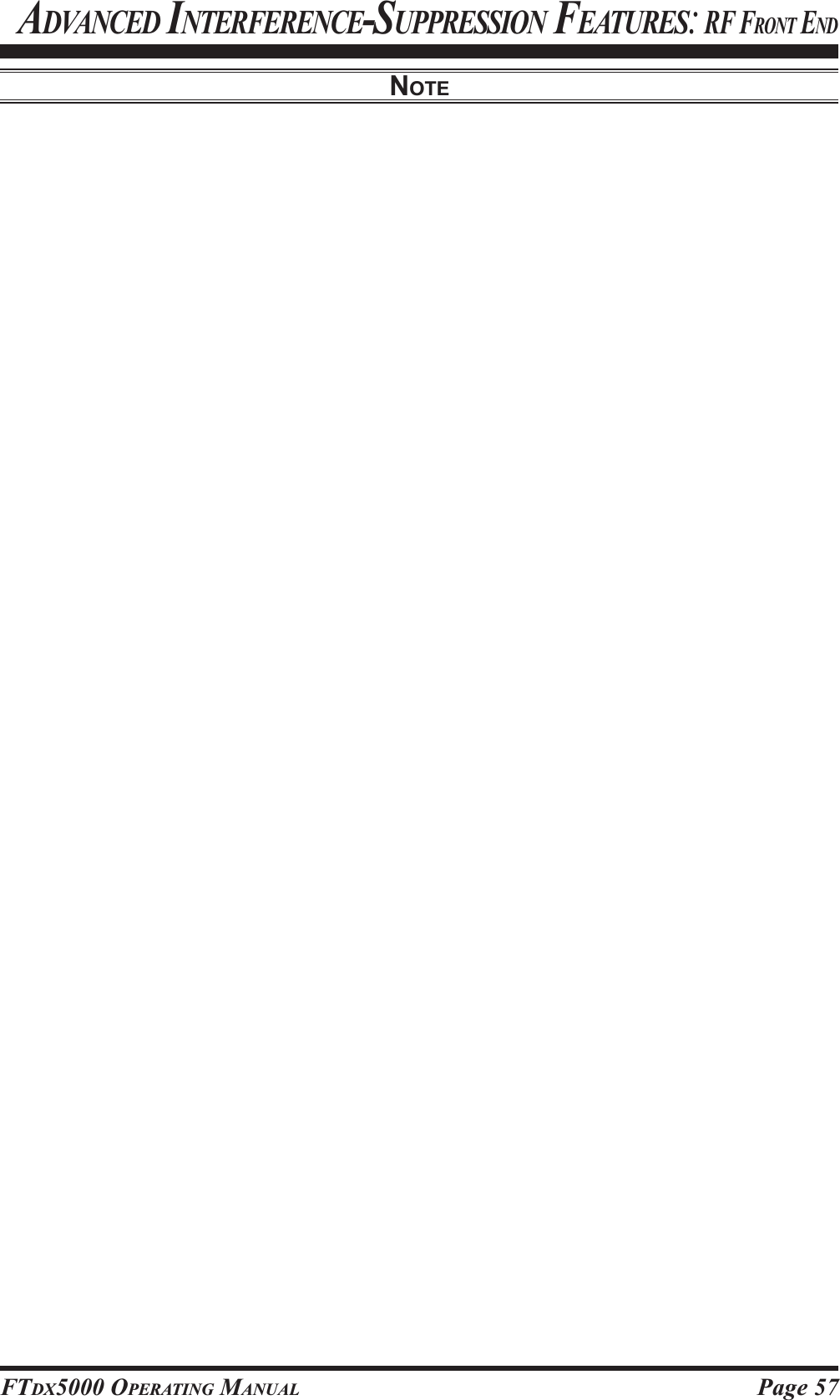
![Page 58 FTDX5000 OPERATING MANUALCONTOUR CONTROL OPERATIONThe Contour filtering system provides a gentle perturbation of the IF filter passband, so as to suppress or enhance certainfrequency components, thus enhancing the sound and/or readability of a received signal.INTERFERENCE REJECTION (SIGNALS WITHIN 3 KHZ)VFO-A Contour OperationPress the (VFO-A)[CONT/APF] button. The imbed-ded LED in the (VFO-A)[CONT/APF] button is glowsred, and current “null” (or “Peak”) position of the con-tour filter will appears in the SUB DISPLAY-II . The(VFO-A)[SELECT] knob will now functions as thecontour knob.Rotate the (VFO-A)[SELECT] knob to achieve themost natural-sounding audio reproduction on the in-coming signal.Press the (VFO-A)[CLEAR] button to move the “null”(or “Peak”) position to center.To cancel Contour tuning, press the (VFO-A)[CONT/APF] button once more.ADVICE:The contour filter’s level (either nulling or peaking)may be adjusted using Menu item “108 RDSP CNTRLV”. The factory default setting is for a null of “–15–15–15–15–15”(dB).The bandwidth over which the contour filter effect isapplied may be adjusted using Menu item “109 RDSPCNTR WI.” The factory default setting is “1010101010.”When the optional DMU-2000 Data Management Unitis connected, the Audio Scope (on the “Oscilloscope”page) is particularly useful when adjusting the Con-tour control. Not only can you see the effect of thenull/peak of the Contour system, but you also can seethe position of the null/peak with respect to frequencycomponents of interest on the incoming signal. Youmay then observe (on the Audio Scope) the effect ofthe Contour control while listening to the effect on thesignal, and this will help build your intuition on howbest to use Contour tuning in the future.VFO-B Contour OperationPress the (VFO-B)[CONT/APF] button. The imbed-ded LED in the (VFO-B)[CONT/APF] button is glowsred, and current “null” (or “Peak”) position of the con-tour filter will appears in the SUB DISPLAY-III. The(VFO-B)[SELECT] knob will now functions as thecontour knob.Rotate the (VFO-B)[SELECT] knob to achieve themost natural-sounding audio reproduction on the in-coming signal.Press the (VFO-B)[CLEAR] button to move the “null”(or “Peak”) position to center.To cancel Contour tuning, press the (VFO-A)[CONT/APF] button once more.(VFO-A)[SELECT] Knob (VFO-B)[SELECT] Knob(VFO-B)[CONT/APF] Button[CLEAR] Button(VFO-A)[CONT/APF] Button[CLEAR] ButtonQUICK POINT:The steep slopes of the DSP filtering can, when adjustedaggressively, impart an unnatural sound to an incomingsignal. Oftentimes, though, a narrow bandwidth is not thekey to improving copy; the incoming signal itself may haveundesirable or excessive frequency components, especiallyin the low-frequency range around 100-400 Hz. By judi-cious use of the Contour filter, the “shoulder” of the pass-band response may be altered, or components removedfrom within the passband, allowing the desired signal torise above the background noise and interference in a man-ner not obtainable with other filtering systems.HIJKHIJKHIJKHIJKHIJKHIJKHIJKHIJKHIJKHIJKHIJKHIJKHIJKHIJKHIJKHIJKHIJKHIJKHIJKHIJKHIJKHIJKHIJKHIJKHIJKHIJKHIJKHIJK](https://usermanual.wiki/Yaesu-Musen/20361X60.Users-Manual-1/User-Guide-1211678-Page-45.png)