Yaesu Musen 20361X60 HF Transceiver with Scanning Receiver User Manual pmd
Yaesu Musen Co., Ltd. HF Transceiver with Scanning Receiver pmd
UserManual.wiki
>
Yaesu Musen
>
20361X60 User Manual
>
Users Manual 2
Contents
1.
Users Manual 1
2.
Users Manual 2
Users Manual 2
Navigation menu
Upload a User Manual
Namespaces
Wiki Guide
HTML
PDF
Info
Views
User Manual
Discussion / Help
Navigation
![Page 59FTDX5000 OPERATING MANUALCONTOUR CONTROL OPERATIONINTERFERENCE REJECTION (SIGNALS WITHIN 3 KHZ)With reference to Figure “B”, note the initial positionof the contour when the [CONT] button is pushed. Youmay observe the “indentation” in the receiver passbandwhere the contour filter is placing a low-Q “notch” (perthe setting of Menu item “108 RDSP CNTR LV”, ref-erenced previous page). Counter-clockwise rotation (tothe left) of the [SELECT](contour) knob causes theindentation to move towered a lower frequency withinthe passband, while clockwise rotation (to the right)causes the indentation to move toward a higher fre-quency within the passband. By removing interferenceor unwanted frequency components on the incomingsignal, it is possible to make the desired signal rise outof the background noise/interference, enhancing intel-ligibility.IFBANDWIDTHIFBANDWIDTHIFBANDWIDTHABC](https://usermanual.wiki/Yaesu-Musen/20361X60.Users-Manual-2/User-Guide-1211679-Page-1.png)
![Page 60 FTDX5000 OPERATING MANUALIF SHIFT OPERATION (SSB/CW/RTTY/PKT/AM MODES)IF Shift allows you to vary the DSP filter passband higher or lower, without changing the pitch of the incoming signal, so asto reduce or eliminate interference. Because the carrier tuning frequency is not varied, there is no need to re-tune theoperating frequency when eliminating the interference. The total passband tuning range for the IF Shift system is ±1 kHz.INTERFERENCE REJECTION (SIGNALS WITHIN 3 KHZ)VFO-A IF SHIFT OperationPress the (VFO-A)[SHIFT] button. The center posi-tion of the IF passband will appears in the SUB DIS-PLAY-II . The (VFO-A)[SELECT] knob will nowfunctions as the IF SHIFT knob.Rotate the (VFO-A)[SELECT] knob to the left or rightto reduce the interference.Press the (VFO-A)[CLEAR] button to move the filterpassband to center. When the filter passband is set toband center, the imbedded LED in the (VFO-A)[SHIFT] button is glows red.Referring to Figure “A”, note the depiction of the IFDSP filter as the thick line with the no shift (with theimbeded LED of the [SHIFT] button is glows red). InFigure “B”, an interfering signal has appeared insidethe original passband. In Figure “C”, you can see theeffect of rotating the [SELECT](shift) knob so as toreduce the interference level by moving the filter pass-band so that the interference is outside of the pass-band.VFO-B IF SHIFT OperationPress the (VFO-B)[SHIFT] button. The center posi-tion of the IF passband will appears in the SUB DIS-PLAY-III. The (VFO-B)[SELECT] knob will nowfunctions as the IF SHIFT knob.Rotate the (VFO-B)[SELECT] knob to the left or rightto reduce the interference.Press the (VFO-B)[CLEAR] button to move the filterpassband to center. When the filter passband is set toband center, the imbedded LED in the (VFO-B)[SHIFT] button is glows red.(VFO-A)[SELECT] Knob (VFO-B)[SELECT] Knob(VFO-B)[SHIFT] Button[CLEAR] Button(VFO-A)[SHIFT] Button[CLEAR] ButtonABCIFBANDWIDTHIFBANDWIDTHIFBANDWIDTHDesired Signal Desired Signal Desired SignalQRMQRM](https://usermanual.wiki/Yaesu-Musen/20361X60.Users-Manual-2/User-Guide-1211679-Page-2.png)
![Page 61FTDX5000 OPERATING MANUALWIDTH (IF DSP BANDWIDTH) TUNING (SSB/CW/RTTY/PKT MODES)The IF Width tuning system allows you to vary the width of the DSP IF passband, so as to eliminate interference. Moreover,the bandwidth may actually be expanded from its default setting, should you wish to enhance incoming signal fidelity wheninterference on the band is low.INTERFERENCE REJECTION (SIGNALS WITHIN 3 KHZ)VFO-A WIDTH OperationPress the (VFO-A)[WIDTH] button. The current band-width will appears in the SUB DISPLAY-II . The(VFO-A)[SELECT] knob will now functions as theWIDTH knob.Rotate the (VFO-A)[SELECT] knob to the left or rightto reduce the interference.Press the (VFO-A)[CLEAR] button to set the band-width to default. When the bandwidth is set to default,the imbedded LED in the (VFO-A)[WIDTH] button isglows red.VFO-B WIDTH OperationPress the (VFO-B)[WIDTH] button. The current band-width will appears in the SUB DISPLAY-III. The(VFO-B)[SELECT] knob will now functions as theWIDTH knob.Rotate the (VFO-B)[SELECT] knob to the left or rightto reduce the interference.Press the (VFO-B)[CLEAR] button to set the band-width to default. When the bandwidth is set to default,the imbedded LED in the (VFO-B)[WIDTH] buttonis glows red.Referring to Figure “B”, you can see the default band-width (with the imbeded LED of the [WIDTH] buttonis glows red).By rotating the [SELECT](width) knob to the left, thebandwidth will narrow (see Figure “A”), while rota-tion of the [SELECT](width) knob to the right, as de-picted in Figure “C,” will widen the bandwidth.The default bandwidths, and total bandwidth adjust-ment range, will vary according to the operating modeand [NAR] button setting:(VFO-A)[SELECT] Knob (VFO-B)[SELECT] Knob(VFO-B)[WIDTH] Button[CLEAR] Button(VFO-A)[WIDTH] Button[CLEAR] ButtonNOTE:When rotating the [SELECT](WIDTH) knob counter-clockwise, the transition between 50 Hz and 25 Hz band-width may be accompanied by a “ping” sound, dependingon the amount of noise present. This is a normal condi-tion, and you should turn down the volume, when wearingheadphones, to minimize the amplitude of this momentarysound.OFF1.8 kHz - 4.0 kHz / 16 steps (2.4 kHzÚ)500 Hz - 2.4 kHz / 7 steps (2.4 kHzÚ)500 Hz - 2.4 kHz / 7 steps (500 HzÚ)500 Hz - 2.4 kHz / 7 steps (500 HzÚ)ON200 Hz - 1.8 kHz / 9 steps (1.8 kHzÚ)50 Hz - 500 Hz / 10 steps (500 HzÚ)50 Hz - 500 Hz / 10 steps (300 HzÚ)50 Hz - 500 Hz / 10 steps (300 HzÚ)MODELSB/USBCWRTTY(LSB)PKT(LSB/USB)NAR SWITCHÚ: Default (the imbeded LED of the [WIDTH] button is glows red)IFBANDWIDTHIFBANDWIDTHIFBANDWIDTHABC](https://usermanual.wiki/Yaesu-Musen/20361X60.Users-Manual-2/User-Guide-1211679-Page-3.png)
 knob after press-ing the [WIDTH] button (the imbeded LED of the[WIDTH] button is glows red), as shown in Figure “B”,the interference from one side can be eliminated, then pressthe by [SHIFT] button to change the function of the [SE-LECT] knob as the SHIFT knob (the imbeded LED of the[SHIFT] button is glows red. However, the IF Width func-tion still works). Now, re-positioning the [SELECT](shift)knob (Figure “C”), the interference on the opposite sidecan be removed, without re-introducing the interferencepreviously eliminated in Figure “B”.ADVICE:For best interference reduction, the Width and Shift fea-tures are the primary tools you should use. After narrow-ing the bandwidth (width) and/or adjusting the center ofthe passband (shift), the Contour control may also yieldadditional signal-enhancement benefits on the net residualbandwidth. What’s more, the IF Notch Filter (see the nextsection) may also be utilized, in conjunection with the threeother filter systems, to significant advantage.ABC](https://usermanual.wiki/Yaesu-Musen/20361X60.Users-Manual-2/User-Guide-1211679-Page-4.png)
![Page 63FTDX5000 OPERATING MANUALINTERFERENCE REJECTION (SIGNALS WITHIN 3 KHZ)IF NOTCH FILTER OPERATION (SSB/CW/RTTY/PKT/AM MODES)The IF Notch filter is a highly-effective system that allows you to slice out an interfering beat note or other carrier signalfrom inside the receiver passband.VFO-A IF Notch OperationPress the (VFO-A)[NOTCH] button. The imbeddedLED in the (VFO-A)[NOTCH] button is glows red,and current “null” (or “Peak”) position of the IF notchfilter will appears in the SUB DISPLAY-II. The (VFO-A)[SELECT] knob will now functions as the notchadjustment knob.Rotate the (VFO-A)[SELECT] knob to adjust the cen-ter frequency of the IF notch filter.Press the (VFO-A)[CLEAR] button to move the “null”position to center.To switch the IF notch filter off, press the (VFO-A)[NOTCH] button once more.The performance of the IF notch filter is shown inFigure “A”, where the effect of rotation of the[SELECT](notch) knob is depicted. In Figure “B”,you can see the notching effect of the IF notch fil-ter as you rotate the [SELECT](notch) knob toeliminate the incoming interference.VFO-B IF Notch OperationPress the (VFO-B)[NOTCH] button. The imbeddedLED in the (VFO-B)[NOTCH] button is glows red,and current “null” (or “Peak”) position of the IF notchfilter will appears in the SUB DISPLAY-III. The(VFO-B)[SELECT] knob will now functions as thenotch adjustment knob.Rotate the (VFO-B)[SELECT] knob to adjust the cen-ter frequency of the IF notch filter.Press the (VFO-B)[CLEAR] button to move the “null”position to center.To switch the IF notch filter off, press the (VFO-B)[NOTCH] button once more.ADVICE:The width of the IF notch null may be adjusted usingMenu item “110 RDSP NOTCH WI”. Both “Wide”and “Narrow” selections are available, with “Narrow”providing the least disruption of the “desired” signal.When the optional DMU-2000 Data Management Unitis connected, the effect of the IF notch filter may beobserved on the Audio Scope (on the “Oscilloscope”page). The notch will be observed as a “dip” in thenoise platform observed. What’s more, the “Waterfall”display may be used to observe the effect of the IFnotch filter, which will appear as a white area in thecolored background area. The tuning rate for the IFnotch is somewhat slow while you adjust the[SELECT](notch) knob, so the use of the Waterfalldisplay to confirm proper adjustment is highly recom-mended.(VFO-A)[SELECT] Knob[CLEAR] Button(VFO-A)[NOTCH] Button(VFO-B)[SELECT] Knob[CLEAR] Button(VFO-B)[NOTCH] ButtonIFBANDWIDTHQRM(Heterodyne)QRM(Heterodyne)IFBANDWIDTHDesired Signal Desired SignalAB](https://usermanual.wiki/Yaesu-Musen/20361X60.Users-Manual-2/User-Guide-1211679-Page-5.png)
![Page 64 FTDX5000 OPERATING MANUALDIGITAL NOISE REDUCTION (DNR) OPERATIONThe Digital Noise Reduction (DNR) system is designed to reduce the level of random noise found on the HF and 50 MHzbands, and it is especially effective during SSB operation. By rotating the [DNR] knob, any of 15 different noise-reductionalgorithms can be selected; each of these algorithms was created for dealing with a different noise profile, and you will wantto experiment with the DNR system to find the best setting according to the noise currently being experienced.INTERFERENCE REJECTION (SIGNALS WITHIN 3 KHZ)VFO-A DNR OperationPress the (VFO-A)[DNR] button. The imbedded LEDin the (VFO-A)[DNR] button is glows red, and cur-rent noise-reduction algorithm will appears in the SUBDISPLAY-II. The (VFO-A)[SELECT] knob will nowfunctions as the notch adjustment knob.Rotate the (VFO-A)[SELECT] knob to select the set-ting that most effectively reduces the noise level.Press the (VFO-A)[CLEAR] button to set the noise-reduction algorithm to default.To switch the DNR system off, press the (VFO-A)[NOTCH] button once more.DIGITAL NOTCH FILTER (DNF) OPERATIONThe Digital Notch Filter (DNF) is an effective beat-cancelling filter that can null out a number of interfering beat notesinside the receiver passband. Because this is an Auto-Notch feature, there is no adjustment knob associated with this filter.ADVICE:If a very strong interfering carrier is encountered, we recommend you first use the IF notch filter, as it is the most effectivenotching tool in the receiver section.VFO-A DNF OperationPress the (VFO-A)[DNF] button. The imbedded LEDin the (VFO-A)[DNF] button is glows red, confirmingthat the DNF system is engaged.To switch the DNF system off, press the (VFO-A)[DNF] button once more.VFO-B DNR OperationPress the (VFO-B)[DNR] button. The imbedded LEDin the (VFO-B)[DNR] button is glows red, and cur-rent noise-reduction algorithm will appears in the SUBDISPLAY-II. The (VFO-B)[SELECT] knob will nowfunctions as the notch adjustment knob.Rotate the (VFO-B)[SELECT] knob to select the set-ting that most effectively reduces the noise level.Press the (VFO-B)[CLEAR] button to set the noise-reduction algorithm to default.To switch the DNR system off, press the (VFO-B)[NOTCH] button once more.(VFO-A)[SELECT] Knob (VFO-B)[SELECT] Knob(VFO-B)[DNR] Button[CLEAR] Button(VFO-A)[DNR] Button[CLEAR] Button(VFO-A)[DNF] Button (VFO-B)[DNF] ButtonVFO-A DNF OperationPress the (VFO-B)[DNF] button. The imbedded LEDin the (VFO-B)[DNF] button is glows red, confirmingthat the DNF system is engaged.To switch the DNF system off, press the (VFO-B)[DNF] button once more.](https://usermanual.wiki/Yaesu-Musen/20361X60.Users-Manual-2/User-Guide-1211679-Page-6.png)
![Page 65FTDX5000 OPERATING MANUALINTERFERENCE REJECTION (SIGNALS WITHIN 3 KHZ)NARROW (NAR) ONE-TOUCH IF FILTER SELECTIONVFO-B “One-Touch Narrow” OperationPress the [B] button (the imbedded LED in the [B]button is glows orange).Pressing the [NAR] button provides one-touch, mode-specific selection of a narrow IF DSP filter setting thatdoes not depend on the setting of the [WIDTH] knob.Pressing the [NAR] button once more returns the band-width control to the Width/Shift system. The factorydefault of the bandwidth is as shown below.ADVICE:When the narrow bandwidth is selected, the “ ” iconwill appear in the display, and the bandwidth on the SUBDISPLAY-III will be reduced if the SUB DISPLAY-IIIindicates the bandwidth.VFO-A “One-Touch Narrow” OperationPress the [A] button (the imbedded LED in the [A]button is glows red), if desired.Pressing the [NAR] button provides one-touch, mode-specific selection of a narrow IF DSP filter setting thatdoes not depend on the setting of the [WIDTH] knob.Pressing the [NAR] button once more returns the band-width control to the Width/Shift system. The factorydefault of the bandwidth is as shown below.ADVICE:ADVICE:When the narrow bandwidth is selected, the “ ” iconwill appear in the display, and the bandwidth on the SUBDISPLAY-II will be reduced if the SUB DISPLAY-II in-dicates the bandwidth.[A] Button [B] Button[NAR] Button [NAR] ButtonOFF2.4 kHz (1.8 kHz - 4.0 kHz / 16 stepsÚ)2.4 kHz (500 Hz - 2.4 kHz / 7 stepsÚ)500 Hz (500 Hz - 2.4 kHz / 7 stepsÚ)500 Hz (500 Hz - 2.4 kHz / 7 stepsÚ)25 kHz (±5.0 kHz Deviation)9 kHz25 kHz (±5.0 kHz Deviation)ON1.8 kHz (200 Hz - 1.8 kHz / 9 stepsÚ)500 Hz (50 Hz - 500 Hz / 10 stepsÚ)300 Hz (50 Hz - 500 Hz / 10 stepsÚ)300 Hz (50 Hz - 500 Hz / 10 stepsÚ)12.5 kHz (±2.5 kHz Deviation)6 kHz12.5 kHz (±2.5 kHz Deviation)MODELSB/USBCWRTTY(LSB)PKT(LSB/USB)PKT(FM)AMFMNAR BUTTON](https://usermanual.wiki/Yaesu-Musen/20361X60.Users-Manual-2/User-Guide-1211679-Page-7.png)
![Page 66 FTDX5000 OPERATING MANUALIF NOISE BLANKER (NB) OPERATIONThe FTDX5000 includes an effective IF Noise Blanker, which can significantly reduce noise caused by automotive ignitionsystems.VFO-A NB OperationPress the [A] button (the imbedded LED in the [A]button is glows red), if desired.Press the [NB] button briefly to reduce short durationpulse noise such as from switching transients, auto-mobile ignitions and power lines. The “ ” icon willappear in the display to confirm that the Narrow-NB isoperating.Press and hold in the [NB] button for two seconds toreduce longer-duration man-made pulse noise. The“” icon will blink for three seconds, and there-after will appear continuously, to confirm that the Wide-NB is operating.Rotate the (VFO-A)[NB] knob to the point where theoffending noise is best reduced or eliminated.To end Noise Blanker operation, press the [NB] but-ton once more. The “ ” (or “ ”) icon willturn off, confirming that the Noise Blanker is no longerin operation.INTERFERENCE REJECTION (SIGNALS WITHIN 3 KHZ)VFO-B NB OperationPress the [B] button (the imbedded LED in the [B]button is glows orange).Press the [NB] button briefly to reduce short durationpulse noise such as from switching transients, auto-mobile ignitions and power lines. The “ ” icon willappear in the display to confirm that the Narrow-NB isoperating.Press and hold in the [NB] button for two seconds toreduce longer-duration man-made pulse noise. The“” icon will blink for three seconds, and there-after will appear continuously, to confirm that the Wide-NB is operating.Rotate the (VFO-B)[NB] knob to the point where theoffending noise is best reduced or eliminated.To end Noise Blanker operation, press the [NB] but-ton once more. The “ ” (or “ ”) icon will turnoff, confirming that the Noise Blanker is no longer inoperation.[A] Button [NB] Knob [B] Button [NB] Knob(VFO-A)[NB] Knob (VFO-B)[NB] Knob](https://usermanual.wiki/Yaesu-Musen/20361X60.Users-Manual-2/User-Guide-1211679-Page-8.png)
![Page 67FTDX5000 OPERATING MANUALAGC (AUTOMATIC GAIN CONTROL)The AGC system is designed to help compensate for fading and other propagation effects, with characteristics that can beof particular value on each operating mode. The basic objective of AGC is to maintain a constant audio output level oncea certain minimum threshold of signal strength is achieved.VFO-A AGC SelectionPress the [A] button (the imbedded LED in the [A]button is glows red), if desired.Move the [AGC] knob up and down to set the desiredreceiver-recovery time constant of the VFO-A receiver.The selected receiver-recovery time will be indicatedin the AGC column of the Block Diagram Display onthe display.Hold up or hold down the [AGC] knob for two sec-onds to disable the AGC (for testing or weak-signalreception).For most operation, we recommend the “AUTO” modeby pressing the [AGC] knob briefly or move the [AGC]knob to select the ATT display to the “AUTO” posi-tion.VFO-B AGC SelectionPress the [B] button (the imbedded LED in the [A]button is glows orange).Move the [AGC] knob up and down to set the desiredreceiver-recovery time constant of the VFO-A receiver.The selected receiver-recovery time will be indicatedin the AGC column of the Block Diagram Display onthe display.Hold up or hold down the [AGC] knob for two sec-onds to disable the AGC (for testing or weak-signalreception).For most operation, we recommend the “AUTO” modeby pressing the [AGC] knob briefly or move the [AGC]knob to select the ATT display to the “AUTO” posi-tion.TOOLS FOR COMFORTABLE AND EFFECTIVE RECEPTIONNOTE:When the AGC receiver-recovery time is set to “OFF”,the S-meter will no longer deflect. Additionally, youwill likely encounter distortion on stronger signals, asthe IF amplifiers and the following stages are prob-ably being overloaded.Normally, the “AUTO” selection is satisfactory formost situations, but in the event of operation on acrowded band where you wish to receive a weak sig-nal, you may wish to change the setting (to “FAST”,for example). The “AUTO” mode selections are:[A] Button[AGC] Knob[B] Button[AGC] KnobADVICE:When a received signal becomes degraded due to pulsetype noise, you may improve signal readability by settingthe Menu items “002 AGC FST HLD”, “004 AGC MIDHLD”, and “006 AGC SLW HLD” to “0 msec”.QUICK POINTSeveral aspects of AGC performance may be configuredvia the Menu. However, because AGC can have such aprofound impact on overall receiver performance, we gen-erally do not recommend any changes to the AGC Menuselections until you are thoroughly familiar with the per-formance of the FTDX5000.TERMINOLOGY:Automatic Gain Control, or AGC, is a circuit that sensesthe incoming signal strength, and then limits the gains ofthe RF and IF stages so as to keep the output audio vol-ume at a more-or-less constant level. AGC also protectsthe RF, IF, Audio, and DSP stages from overload, as itlimits the signal strength that is allowed to flow, irrespec-tive of the input signal level.OPERATING MODELSBUSBCWAMFMRTTYPKT (FM)PKT (LSB)AUTO AGC SELECTIONSLOWSLOWFASTFASTFASTSLOWFASTSLOWHIJKHIJKHIJKHIJKHIJKHIJKHIJKHIJKHIJKHIJKHIJKHIJKHIJKHIJKHIJKHIJKHIJKHIJKHIJKHIJKHIJKHIJKHIJKHIJKHIJKHIJKHIJKHIJK](https://usermanual.wiki/Yaesu-Musen/20361X60.Users-Manual-2/User-Guide-1211679-Page-9.png)
![Page 68 FTDX5000 OPERATING MANUALTOOLS FOR COMFORTABLE AND EFFECTIVE RECEPTIONAGC (AUTOMATIC GAIN CONTROL)SLOPED AGC OperationIn traditional AGC systems, the audio output from the transceiver becomes essentially fixed once the threshold forAGC action is reached (usually several dozen dB above the no-signal noisefloor). The FTDX5000, however, includes an innovative Sloped AGC sys-tem on the VFO-A receiver, that allows the audio volume to rise and fallslightly according to signal strength. Although the rise/fall slope is not dra-matic, it is sufficient to allow you to use your ear to discern and separatesignals according to signal strength, not just audio frequency.NORMALInput SignalAudio OutputSLOPEDUsing Sloped AGC1. Press the [MENU] button briefly to enter the Menumode.2. Use the (VFO-A)[SELECT] to select Menu item“103 ROUT AGC SLP”.3. Rotate the (VFO-B)[SELECT] to change the set-ting to “SLOPE”.4. Press and hold in the [MENU] button for two sec-onds to save the new setting and exit to normal op-eration. You will now be using the Sloped AGCsystem.(VFO-B)[SELECT] Knob[MENU] Button(VFO-A)[SELECT] Knob](https://usermanual.wiki/Yaesu-Musen/20361X60.Users-Manual-2/User-Guide-1211679-Page-10.png)
![Page 69FTDX5000 OPERATING MANUALMUTE FEATURE (MAIN (VFO-A) BAND)TOOLS FOR COMFORTABLE AND EFFECTIVE RECEPTIONThere may be occasions, during Dual Receive operation,when you want to silence the VFO-A receiver temporarilyso as to concentrate on what’s being received on the VFO-B receiver. The Mute feature makes this simple to accom-plish.Press the (VFO-A)[RX] button, located to the upper leftof the Main Tuning Dial knob. The VFO-A receiver willbe silenced, and the green LED in the (VFO-A)[RX] but-ton will blink.To restore reception on the VFO-A receiver, just press theblinking (VFO-A)[RX] button once more.ADVICE:If you press the [POWER] switch momentarily while thetransceiver is turned on, the transceiver’s audio will bemuted for three seconds.[A] Button[POWER] Switch](https://usermanual.wiki/Yaesu-Musen/20361X60.Users-Manual-2/User-Guide-1211679-Page-11.png)
![Page 70 FTDX5000 OPERATING MANUAL1. The operating mode is se-lected using the [MODE]buttons, and the VFO (A orB) to which the selection isapplied is selected by the [A]or [B] button, located to theupper left of the Main Tun-ing Dial knob. Usually,the [A] button glowsred, signifying that theVFO-A is being ad-justed. Similarly, press-ing the [B] button willcause its indicator toglows orange, signifying VFO-B adjustment. There-fore, press the [A] or [B] button to select the desiredVFO, then press the [LSB] or [USB] button to selectone of the SSB modes. For AM operation, press the[AM/FM] button repeatedly until the “ ” icon ap-pears in the display.QUICK POINT:By convention, LSB is used in the 7 MHz and lowerAmateur bands for SSB communication, and USB isused on the 14 MHz and higher bands (the 10 MHzband is used for CW and data modes only).2. Rotate the Main Tuning Dial knob to adjust the oper-ating frequency. Alternatively, you may use the [UP]/[DWN] scanning buttons on the MH-31B8 Hand Mi-crophone to sweep up or down the current band.3. Press the microphone’s PTT (Push To Talk) switch tobegin transmission; speak into the microphone in anormal voice level.ADVICE:The “ ” indicator will light up in the frequencydisplay area, confirming that transmission is inprogress.When transmitting in the AM mode, rotate the [RFPWR] knob so as to set a maximum (carrier) poweroutput of 25 Watts.4. In the SSB mode, adjust the micro-phone amplifier gain to match themicrophone and your voice level,set the [METER] switch to the“ALC” position, close the PTTswitch, speak into the microphone ina normal voice level, and adjust the[MIC] (gain) knob so that the ALCvoltage stays within the blue ALCzone of the meter (up to 2/3 of fullscale deflection) on voicepeaks.ADVICE:The microphone gain ofthe AM mode has been programmed, at the fac-tory, to a level that should be satisfactory for mostsituations. However, using Menu item “047 A3EMICGAIN,” you may set a different fixed value,or choose the “MCVR” option, which then lets youuse the front panel [MIC] knob to set the micro-phone gain in the AM mode. In this case, the [MIC]knob should not be advanced to the point wherethe ALC meter deflects. In many cases, the samesetting as used on SSB will be satisfactory.The SUB DISPLAYs will show the relative Mi-crophone Gain level for 3 seconds whenever the[MIC] knob is turned.You may disable this feature (displaying the rela-tive Microphone Gain level) via Menu item “015DISP LVL IND”. See page ??? for details.5. Release the PTT switch at the end of your transmis-sion. The transceiver will return to the receive mode.SSB/AM MODE TRANSMISSIONMain Tuning Dial knob[METER] Switch [B] Button[MOX] Button[MODE] Buttons[MIC] Knob[RF PWR] Knob[A] Button](https://usermanual.wiki/Yaesu-Musen/20361X60.Users-Manual-2/User-Guide-1211679-Page-12.png)
![Page 71FTDX5000 OPERATING MANUALSSB/AM MODE TRANSMISSIONADVICE:ALC meter deflection may be caused by excessive drivepower, but also by reflected power detected in the an-tenna system. If the impedance presented to the trans-ceiver is different from 50 Ohms, ALC meter actionmay be observed that is not related to the proper set-ting of the [MIC] (gain) knob. Therefore, we recom-mend that you make [MIC] knob adjustments into adummy load or antenna system presenting an imped-ance very close to 50 Ohms.Rotate the [RF PWR] knob to set the desired poweroutput. Clockwise rotation of the [RF PWR] knob willincrease the power. The adjustmentrange is between 10 Watts and 200Watts, and you should always use theminimum power necessary for main-taining reliable communications.The SUB DISPLAYs will show the RF Power Outputfor 3 seconds whenever the [RF PWR] knob is turned.You may disable this feature (displaying the RF PowerOutput) via Menu item “015 DISP LVL IND”. Seepage ??? for details.The analog PO meter indicates the average power out-put level. SSB transmit average talk power is normally10% to 50% of the peak power output. Voice charac-teristics, microphone qualities, parametric equalizerand compression settings affect actual talk power out-put.When performing tests (such as the setup of the [MIC]or [RF PWR] knobs), be sure to check the frequencybefore transmitting, so as to avoid interference to oth-ers who may already be using the frequency.Four techniques for exercising Transmit/Receive con-trol are provided on the FTDX5000, and you maychoose the technique(s) that best suit your operatingneeds:Pressing the microphone’s PTT switch will engagethe transmitter.The rear panel PTT jack may be connected to afoot switch or other manual switching device inorder to engage the transmitter.Pressing the front panel [MOX] button will lockthe transmitter on. Press the [MOX] button againto return to receive.The VOX (Voice Operated Xmit) circuit will en-gage the transmitter automatically when you speakinto the microphone. For details of VOX opera-tion, see page 74.](https://usermanual.wiki/Yaesu-Musen/20361X60.Users-Manual-2/User-Guide-1211679-Page-13.png)
![Page 72 FTDX5000 OPERATING MANUALThe Automatic Antenna Tuner (hereinafter referred to as the “ATU”) built into each FTDX5000 is crafted to ensure a 50-Ohm load for the final amplifier stage of the transmitter. We recommend that the ATU be used whenever you operate on theFTDX5000.ADVICE:The ATU of the FTDX5000, being located inside the station, only adjusts the impedance presented to the transceiver atthe station end of your coaxial cable feedline. It does not “tune” the SWR at the antenna feedpoint itself. When design-ing and building your antenna system, we recommend that every effort be made to ensure a low SWR at the antennafeedpoint.The ATU of the FTDX5000 includes 100 memories for tuning data. Eleven of these memories are allocated, one perAmateur band, so that each band has at least one setting preset for use on that band. The remaining 89 memories arereserved for the 89 most-recent tuning points, for quick frequency change without the need to retune the ATU.The ATU in the FTDX5000 is designed to match impedances within the range of 16.5 Ohms to 150 Ohms, correspond-ing to an SWR of 3:1 or less on the HF amateur bands (6 m amateur band: 25 Ohms to 100 Ohms, corresponding to anSWR of 2:1 or less). Accordingly, simple non-resonant whip antennas, along with random-length wires and the “G5RV”antenna (on most bands) may not be within the impedance matching range of the ATU.ATU OPERATIONUSING THE AUTOMATIC ANTENNA TUNER1. Rotate the [RF PWR] knob fully clockwise (to theright).2. Use the Main Tuning Dial knob to set the radio to thedesired operating frequency within the Amateur band.3. Press the [TUNE] button briefly to place the ATU inthe transmit line (no adjustment/tuning will occur yet).The “ ” icon will appear in the display.QUICK POINT:The momentarily press of the [TUNE] button will turnthe tuner on, and the microprocessor will automaticallyselect the tuning point closest to the current operatingfrequency.4. Press and hold in the [TUNE] button for two secondsto begin automatic tuning. The transmitter will be en-gaged, and the “ ” icon will blink while tuning isin progress. When the optimum tuning point has beenreached, the radio will return to receive, and the“” icon will again glow steadily (instead ofblinking).5. While tuning around the band using the Main TuningDial knob, you will observe that the “ ” iconblinks momentarily every 10 kHz. This momentaryblinking indicates that a new tuning window has beenentered. If you want to save tuning data associated withthis 10 kHz window, repeat step 4 (above) for eachsuch window. On bands like 1.8 MHz where the im-pedance may change rapidly, the storage of a numberof tuning points is recommended.6. To disconnect the ATU from the transmit line, pressthe [TUNE] button briefly. The “ ” icon will turnoff, confirming that the ATU has been turned off. Inthe “Off” mode, the transceiver will be directly con-nected to the coaxial cable connected to your antenna,and will operate based on whatever impedance ispresent at the station end of the coax.ADVICE:The ATU circuit is located between the final amplifier andthe rear-panel antenna jack; reception is not affected bythe ATU.QUICK POINT:As shipped from the factory, only one ATU alignmentpoint is saved on each Amateur band. This was memo-rized during the final alignment and performance veri-fication stages on the production line.The momentary flickering of the “ ” icon occurswhenever you cross over into a new 10 kHz ATUmemory window.NOTE:Please check the operating frequency before beginning thetuning process, to be sure you are not interfering with oth-ers who may already be using the frequency.TERMINOLOGY:Antenna Tuner Memories: The microprocessor of the ATUmakes a note of the positions of the tuning capacitors andthe selected inductors, and stores the data for each 10 kHzwindow in which tuning has occurred. This eliminates theneed to re-tune every time you return to a frequency onwhich you already have completed the tuning process.[TUNE] Button[RF PWR] Knob](https://usermanual.wiki/Yaesu-Musen/20361X60.Users-Manual-2/User-Guide-1211679-Page-14.png)
![Page 73FTDX5000 OPERATING MANUALABOUT ATU OPERATIONFigure 1 depicts a situation where normal tuning via the ATU has been successfully completed, and the tuning data has beenstored in the ATU memory. The antenna system as seen by the transmitter is shown.In Figure 2, the operator has changed frequency, and the “ ” icon has become appeared. The operator presses andholds in the [TUNE] button for two seconds to begin impedance matching using the ATU.If a high SWR conditions exists (above 3:1), corrective action must be taken in the antenna system to bring the impedancecloser to 50 Ohms. Besides the fact that the ATU will refuse to memorize settings on frequencies where the SWR exceeds3:1, the high SWR may indicate a mechanical failure in the feed system, and such failures can lead to the generation ofspurious signals causing TVI, etc.About ATU MemoriesSWR (Post-tuning) Less than 1.5:1The tuning settings are committed to the ATU memory.SWR (Post-tuning) Greater than 1.5:1Tuning data will not be retained in memory. If you return to the same frequency, the tuning process must be repeated.SWR (Post-tuning) Greater than 3:1The “ ” icon will light up, and tuning settings, if achieved, will not be memorized. Please investigate andresolve the high SWR condition before attempting further operation using this antenna.USING THE AUTOMATIC ANTENNA TUNERSWR: 2.0FrequencySWR: 1.5Feed Point SWRSWR after ATU TuningSWR: 1.0FIGURE 1FIGURE 2SWR: 3.0SWR: 3.0FrequencySWR: 2.0Memorized ATU TuningRetuned SettingSWR: 1.0The “ ” icon appears on the displaywhen you transmit on this frequency](https://usermanual.wiki/Yaesu-Musen/20361X60.Users-Manual-2/User-Guide-1211679-Page-15.png)
![Page 74 FTDX5000 OPERATING MANUALPARAMETRIC MICROPHONE EQUALIZER (SSB/AM/FM MODES)The FTDX5000 includes a unique Three-Band Parametric Microphone Equalizer, that provides precise, independent con-trol over the low-, mid-, and treble-ranges in your voice wave-form. You may utilize one group of settings for when thespeech processor is off, and an independent group of settings for when the speech processor is on.Setup of the Parametric Microphone Equalizer1. Connect the microphone to the MIC jack.2. Set the [RF PWR] knob to its minimum value, so asnot to cause interference to other users during adjust-ment.ADVICE:We recommend you consider connecting a dummyload to one of the Antenna jacks, and monitor yoursignal on a separate receiver, so as to prevent inter-ference to other users.You will have the best chance of hearing the ef-fects of adjustments if you wear headphones (con-nected to the monitor receiver) while monitoringyour transmitted signal.3. To adjust the Parametric Microphone Equalizer whilethe speech processor is disabled, press the [PROC]button until the “ ” icon appears (or blinks) inthe display. To adjust the Parametric MicrophoneEqualizer with the speech processor engaged, press the[PROC] button until the “ ” and “ ” iconappears in the display.ADVICE:A blinking “ ” icon indicates the ParametricMicrophone Equalizer menu setting have all been setto “OFF”, described later.4. Press the [MONI] button, if you want to listen on theFTDX5000’s internal monitor. Adjust the monitor levelby the [MONI] knob.5. Press the [MENU] button briefly. The Menu list willappear in the display.6. Rotate the (VFO-A)[SELECT] knob to find the“TAUD” Menu area, containing Menu items “145”through “153”; these parameters apply to the adjust-ment of the Parametric Microphone Equalizer whenthe speech processor is disabled. Menu items “154”through “162” apply to the adjustment of the Paramet-ric Microphone Equalizer when the speech processoris engaged.7. Rotate the (VFO-B)[SELECT] knob to perform ad-justments to a particular Menu item.8. Press the PTT switch, and speak into the microphonewhile listening to the effects of the changes you aremaking (in step 6). Because the overall effect on thesound will change with each adjustment you make, youshould make several passes through each adjustmentarea, to be sure that you are achieving the optimumsetting.9. When you have completed all adjustments, press andhold in the [MENU] button for two seconds to savethe new settings and exit to normal operation. If youonly press the [MENU] button momentarily to exit,any changes you performed will not be stored.ADVICE:To roll off excessive bass response in a wide-range studiomicrophone, try putting a 10 dB null at 100 Hz with abandwidth of “1” or “2,” do about a 3 dB null centered on800 Hz with a bandwidth of “3,” and then put an 8 dBpeak centered on 2100 Hz with a bandwidth of “1.” Theseare starting recommendations; each microphone and user’svoice will be different, often requiring different settings.(VFO-B)[SELECT] Knob[MENU] Button(VFO-A)[SELECT] Knob[MONI] Button[MONI] Knob[PROC] ButtonENHANCING TRANSMIT SIGNAL QUALITYQUICK POINT:The Parametric Equalizer is a unique technique for adjusting the signal quality. Because the three ranges may be adjustedso precisely, it is possible to craft a response that provides a more natural and pleasant sound than you have ever experi-enced before. Effective “talk power” can also be significantly enhanced.The aspects of configuration that you may adjust on the Parametric Equalizer are:Center Frequency: The center frequency of each of the three bands may be adjusted.Gain: The amount of enhancement (or suppression) within each band may be adjusted.Q: The bandwidth over which the equalization is applied may be adjusted.](https://usermanual.wiki/Yaesu-Musen/20361X60.Users-Manual-2/User-Guide-1211679-Page-16.png)
![Page 75FTDX5000 OPERATING MANUALPARAMETRIC MICROPHONE EQUALIZER (SSB/AM/FM MODES)QQQQQf3f2f1100 700Hzጚ700 1500Hzጚ1500 3200HzጚQ+10dB-10dB-20dBParametric Gain0 dBActivating the Parametric Microphone Equalizer1. Adjust the [MIC] (gain) knob for SSB use, as describedon page ??.2. Press the [PROC] button briefly. The “ ” iconwill appear in the display, confirming that the Para-metric Microphone Equalizer is engaged.ADVICE:A blinking “ ” icon indicates the ParametricMicrophone Equalizer menu setting have all been setto “OFF” (“145 TAUD EQ1 FRQ”, “148 TAUD EQ2FRQ”, and “151 TAUD EQ3 FRQ”).3. Press the PTT switch on the microphone, and speakinto the microphone in a normal voice level.4. To switch the Parametric Microphone Equalizer off,press the [PROC] button repeatedly until the “ ”icon disappears.[PROC] Button[MIC] Knob3-STAGE PARAMETRIC EQUALIZER ADJUSTMENTS (SPEECH PROCESSOR: “OFF”)Center Frequency “145 TAUD EQ1-FREQ” (Low)“100” (Hz) ~ “700” (Hz)“148 TAUD EQ2-FREQ” (Mid)“700” (Hz) ~ “1500” (Hz)“151 TAUD EQ3-FREQ” (High)“1500” (Hz) ~ “3200” (Hz)Parametric Gain “146 TAUD EQ1-LVL” (Low)“–20” (dB) ~ “+10” (dB)“149 TAUD EQ2-LVL” (Mid)“–20” (dB) ~ “+10” (dB)“152 TAUD EQ3-LVL” (High)“–20” (dB) ~ “+10” (dB)Q (Bandwidth)“147 TAUD EQ1-BW” (Low)“1” ~ “10”“150 TAUD EQ2-BW” (Mid)“1” ~ “10”“153 TAUD EQ3-BW” (High)“1” ~ “10”3-STAGE PARAMETRIC EQUALIZER ADJUSTMENTS (SPEECH PROCESSOR: “ON”)Center Frequency “154 TAUD PE1-FREQ” (Low)“100” (Hz) ~ “700” (Hz)“157 TAUD PE2-FREQ” (Mid)“700” (Hz) ~ “1500” (Hz)“160 TAUD PE3-FREQ” (High)“1500” (Hz) ~ “3200” (Hz)Parametric Gain “155 TAUD PE1-LVL” (Low)“–20” (dB) ~ “+10” (dB)“158 TAUD PE2-LVL” (Mid)“–20” (dB) ~ “+10” (dB)“161 TAUD PE3-LVL” (High)“–20” (dB) ~ “+10” (dB)Q (Bandwidth)“156 TAUD PE1-BW” (Low)“1” ~ “10”“159 TAUD PE2-BW” (Mid)“1” ~ “10”“162 TAUD PE3-BW” (High)“1” ~ “10”ENHANCING TRANSMIT SIGNAL QUALITY20](https://usermanual.wiki/Yaesu-Musen/20361X60.Users-Manual-2/User-Guide-1211679-Page-17.png)
![Page 76 FTDX5000 OPERATING MANUALENHANCING TRANSMIT SIGNAL QUALITYUSING THE SPEECH PROCESSOR (SSB/AM MODES)The Speech Processor is designed to increase “talk power” by increasing the average power output via a sophisticatedcompression technique. The result is improved intelligibility when conditions are difficult.1. Adjust the [MIC] (gain) knob for SSB use, as describedon page ??.2. Press the [PROC] button repeatedly until the “ ”and “ ” icons appear in the display, confirmingthat the Speech Processor is engaged.ADVICE:A blinking “ ” icon indicates the ParametricMicrophone Equalizer menu setting have all been setto “OFF” (“154 TAUD PE1 FRQ”, “157 TAUD PE2FRQ”, and “160 TAUD PE3 FRQ”).3. Adjust the [PROC] knob between 9:00 to 12:00o’clock position.ADVICE:The SUB DISPLAYs will show the relative compres-sion level of the Speech Processor for 3 seconds when-ever the [PROC] knob is turned.You may disable this feature (displaying the relativecompression level) via Menu item “015 DISP LVLIND”. See page ??? for details.4. Rotate the [METER] switch fully to the left, so as toselect “COMP” (Compression).5. Press the PTT switch on the microphone, and speakinto the microphone in a normal voice level. Confirmthat the compression level is within the 5 dB to 10 dBrange.ADVICE:We recommend that adjust the [PROC] knob between9:00 to 12:00 o’clock position as described previously.5. To switch the Speech Procesor off, press the [PROC]button repeatedly until the “ ” and “ ”icons disappears.ADVICE:Excessive advancement of the [PROC] knob will re-sult in a degradation of the transmitted signal’s signal-to-noise ratio, thereby reducing intelligibility at theother end of the circuit.The Transmit Monitor is very helpful way of verifyingproper adjustment of the compression level. Pressingthe [MONI] button then adjusting the [MONI] knobfor a comfortable listening level while you are trans-mitting, you will be able to hear the difference in soundquality as you make adjustments.The [RF PWR] knob still controls the RF power out-put, whether or not the Speech Processor is engaged.When the optional DMU-2000 Data Management Unitis connected, you may observe the effect of your com-pression level adjustments by viewing the wave-formon the “Oscilloscope” page.[METER] Switch[MONI] Button[MONI] Knob[PROC] Knob[MIC] Button[PROC] Button](https://usermanual.wiki/Yaesu-Musen/20361X60.Users-Manual-2/User-Guide-1211679-Page-18.png)
![Page 77FTDX5000 OPERATING MANUALADJUSTING THE SSB TRANSMITTED BANDWIDTH (SSB MODE)For transmission on SSB, a default bandwidth of 2.4 kHz is provided. This bandwidth provides reasonable fidelity alongwith good talk power, and is typical of the bandwidth used for decades during SSB transmission. However, the bandwidthmay be varied by the operator, so as to provide different levels of fidelity or talk power, according to your preferences.ENHANCING TRANSMIT SIGNAL QUALITYHere’s how to adjust the transmitted bandwidth on SSB:1. Press the [MENU] button to engage the Menu.2. Rotate the (VFO-A)[SELECT] knob so as to selectMenu item “100 A3J TX BPF”.3. Rotate the (VFO-B)[SELECT] knob to select the de-sired bandwidth. The available selections are 50-3000,100-2900, 200-2800, 300-2700, 400-2600, and3000WB. The default is 300-2700 Hz. A wider band-width will provide greater fidelity, while a narrow band-width will compress the available transmitter powerinto less spectrum, resulting in more “talk power” forDX pile-ups.4. Press and hold in the [MENU] button for two secondsto save the new setting and exit to normal operation.ADVICE:The Transmit Monitor is very helpful way of verifyingthe effects on fidelity of changing the bandwidth. Press-ing the [MONI] button then adjusting the [MONI] knobfor a comfortable listening level while you are trans-mitting, you will be able to hear the difference in soundquality as you make changes.When the optional DMU-2000 Data Management Unitis connected, you may verify the effect of your adjust-ments of the transmitted bandwidth by observing theAudio Scope on the “Oscilloscope” page.QUICK POINTS:The higher fidelity associated with wide bandwidth willbe particularly enjoyable on the low bands, during lo-cal rag-chew QSOs.The “3000WB” setting is a special hi-fidelity setting,whereby the transmitted bandwidth is in excess of 3kHz. This selection, in conjunction with judicious ad-justment of the Parametric Microphone Equalizer (seenext chapter) can provide truly outstanding fidelity andvery natural-sounding audio.When using the wider bandwidth selections (especially“3000WB”), the apparent power output from the trans-mitter may seem lower. This is because the availablepower from the transmitter is being distributed over awider bandwidth, and the power detection circuitrydoes not compensate for the effect of the bandwidthselection (it is calibrated in the default 2.4 kHz band-width).(VFO-B)[SELECT] Knob[MENU] Button(VFO-A)[SELECT] Knob[MONI] Button[MONI] Knob](https://usermanual.wiki/Yaesu-Musen/20361X60.Users-Manual-2/User-Guide-1211679-Page-19.png)
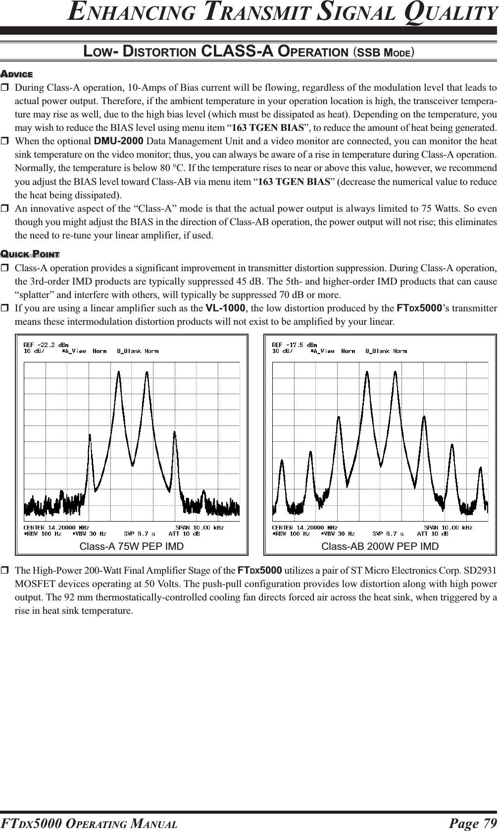
![Page 78 FTDX5000 OPERATING MANUALENHANCING TRANSMIT SIGNAL QUALITYLOW- DISTORTION CLASS-A OPERATION (SSB MODE)Class-A operation of the FTDX5000 transmitter is provided, yielding ultra-low distortion products during SSB operation.Power output during Class-A operation is 75 Watts.1. To engage Class-A operation, press the [CLASS-A]button. The “ ” icon will appear in the display,confirming that Class-A operation has been selected.2. Engaging the “Class-A” mode actually places the trans-ceiver in a condition whereby the Bias level may beadjusted, via the Menu mode.1)Press the [MENU] button to engage the Menu.2)Rotate the (VFO-A)[SELECT] knob so as to se-lect Menu item “163 TGEN BIAS”.3)Rotate the (VFO-B)[SELECT] knob to select thedesired BIAS level “1 - 100” to set the transceiverfor operation anywhere between Class-A and Class-AB (Class-AB has lower heat dissipation but higherdistortion products).A menu setting of “100” will place the transmitterfully in Class-A operation. Counter-clockwise ro-tation of the (VFO-B)[SELECT] knob will movethe transmitter toward Class-AB operation. Themenu setting “1” will place the transmitter fully inClass-AB operation.4)Press and hold in the [MENU] button for two sec-onds to save the new setting and exit to normaloperation.3. To exit from the CLASS-A mode, press the [CLASS-A] switch once more. The “ ” icon disappears,confirming that the CLASS-A mode has been disen-gaged.CLASS-AB CLASS-AId: Drain CurrentVDS: Drain Voltage(VFO-B)[SELECT] Knob[MENU] Button(VFO-A)[SELECT] Knob[CLASS-A] Button](https://usermanual.wiki/Yaesu-Musen/20361X60.Users-Manual-2/User-Guide-1211679-Page-20.png)
![Page 80 FTDX5000 OPERATING MANUALChecking Your Recording1. Be sure that the front panel [MOX] and [VOX] but-tons are both “Off” (the LED imbedded in the buttonmust be off).2. Press the FH-2’s [1] ~ [5] key (whichever one you justrecorded in), and you will hear the contents of the voicememory you just recorded.ADVICE:You may adjust the playback level of the recording viaMenu item “016 DVS RX LVL”.Transmitting the Recorded Message1. Select the LSB, USB, AM, or FM mode using the frontpanel [MODE] buttons.2. Press the front panel’s [BK-IN] button.3. Press the FH-2’s [1] ~ [5] key, depending on whichmemory register’s message you wish to transmit. If youhit the key again during playback, the message will beterminated.ADVICE:You may adjust the transmit (audio) level of the recordingvia Menu item “017 DVS TX LVL”.LOCKOFFONLOCKOFFONVOICE MEMORY (SSB/AM/FM MODES)You may utilize the Voice Memory capability of the FTDX5000 by plugging in the supplied FH-2 Remote Control Keypadinto the rear panel’s REMOTE jack.The Voice Memory system includes five memories capable of storing up to 20 seconds of voice audio each. The maximumthat any memory can hold is 20 seconds.Recording Your Own Voice in Memory1. Select the LSB, USB, AM, or FM mode using the frontpanel [MODE] buttons.2. Press the [MEM] key on the FH-2. A blinking“” icon will appear in the display3. Press any of the FH-2’s keys numbered [1] through[5] to select that memory storage register. If you donot press the PTT key (see next step) within five sec-onds, the memory storage process will be cancelled.4. Press the microphone’s PTT switch briefly, the“” icon will glow steadily, and recording willbegin.5. Speak into the microphone in a normal voice level torecord the message (such as “CQ DX, CQ DX, this isW 6 Delta X-Ray Charlie, W 6 Delta X-Ray Charlie,Over”). Remember that the time limit for recordingany message is 20 seconds.6. Press the FH-2’s [MEM] key to terminate the messagestorage process.TRANSMITTER CONVENIENCE FEATURESLOCKOFFONLOCKOFFON](https://usermanual.wiki/Yaesu-Musen/20361X60.Users-Manual-2/User-Guide-1211679-Page-22.png)
![Page 81FTDX5000 OPERATING MANUALVOX (AUTOMATIC TX/RX SWITCHING USING VOICE CONTROL: SSB/AM/FM MODES)Instead of using the microphone’s PTT switch or the front panel [MOX] switch to activate the transmitter, the VOX (VoiceOperated TX/RX Control) system provides hands-free, automatic activation of the transmitter, based on voice input intothe microphone. Setup of the VOX system takes only a few seconds.1. Adjust the [MIC] (gain) knob for SSB use, as describedon page ??.2. Set the [VOX] and [DELAY] knobs fully counter-clock-wise (to the left).3. Press the [VOX] button to engage VOX operation. Theimbedded LED in the [VOX] button is glows red.4. Speak into the microphone in a normal voice level,and rotate the [VOX] knob clockwise (to the right) untilthe point where your voice input activates the trans-mitter.ADVICE:Do not advance the setting of the [VOX] knob toomuch, because to do so will make the transmitter re-spond to minor background noises in your station.5. Now stop speaking, and note the amount of time it takesfor the receiver to recover. If the hang time is too longor too short; rotate the [DELAY] knob, while speakingbriefly into the microphone and then pausing, so as toset the desired hang time. Clockwise rotation of the[DELAY] knob will increase the hang time.ADVICE:The SUB DISPLAYs will show the hang time of theVOX circuit for 3 seconds whenever the [DELAY]knob is turned.You may disable this feature (displaying the hang timeof the VOX circuit) via Menu item “015 DISP LVLIND”. See page ??? for details.MONITOR (SSB/AM/FM MODES)You may listen to the quality of your transmitted signal using the Monitor feature.1. Press the [MONI] button. The “ ” icon will ap-pear in the display, indicating that the Monitor is turnedon.2. During transmission, rotate the [MONI] knob to ad-just the audio level from the Monitor. Clockwise rota-tion of this knob will increase the volume level.3. To switch the Monitor off again, press the [MONI]button once more. The “ ” icon will turn off,confirming that the Monitor is now disengaged.TRANSMITTER CONVENIENCE FEATURES6. To exit from VOX operation, press the [VOX] buttononce more. We recommend doing this if you are goingto leave your station, to prevent inadvertent activationof the VOX system by a ringing nearby telephone,speaker audio from a TV, etc.ADVICE:The Anti-Trip setting sets the negative feedback of re-ceiver audio to the microphone, to prevent receiveraudio from activating the transmitter (via the micro-phone) can be adjusts via Menu item “168 TGENANTI VOX”.VOX operation may be engaged on either voice modes(SSB/AM/FM) and on AFSK-based data modes. UseMenu item “168 TGEN VOX SEL” (the selectionsare “MIC” and “DATA”).ADVICE:If you are using the speaker for monitoring, instead of headphones, excessive advancement of the [MONI] knob cancause feedback to occur. Additionally, this feedback can cause the VOX system to hang up in a loop, making it impos-sible to return to receive. Therefore, we recommend the use of headphones, if at all possible, or the minimum usablesetting of the [MONI] knob, if the speaker must be used.Because the monitor feature utilizes a sampling of the transmitter’s IF signal, it can be very useful for checking theadjustment of the Speech Processor or Parametric Equalizer on SSB, and for checking the general signal quality on AMand FM.[VOX] Button[VOX] Knob[DELAY] Knob[MIC] Knob[MONI] Button[MONI] Knob](https://usermanual.wiki/Yaesu-Musen/20361X60.Users-Manual-2/User-Guide-1211679-Page-23.png)
![Page 82 FTDX5000 OPERATING MANUALTRANSMITTER CONVENIENCE FEATURESSPLIT OPERATION USING THE TX CLARIFIER (VFO-A OPERATION)For split TX/RX operation in “casual” pile-ups, where the split is less than 10 kHz, the TX Clarifier (Offset Tuning) featuremay be utilized.1. Press the [TX CLAR/LOCK] button. The “ ” and“” icon will appear in the display, and the pro-grammed offset will be applied tothe receive frequency.ADVICE:::::If the “ ” and “ ” icon does not appear, checkto see if the LED imbedded in the [A/B] button glowsorange. If so, pressing the [A/B] button will cause theLED imbedded in the [A/B] button to go out. Now,press the [TX CLAR/LOCK] button to begin clarifieroperation.2. Rotate the [CLAR(VFO-B)] knob to set the desiredtransmitter offset. A maximumsplit of ±9.999 kHz may be set.3. To exit from TX Clarifier operation, press the [TXCLAR/LOCK] button once more. The “ ” icon willdisappear from the display.QUICK POINT:When attempting to work a DX station on CW, in a split-frequency pile-up, remember that a large number of otherstations may also be using Yaesu transceivers with capa-bility similar to that of your FTDX5000. On the DX sideof the pile-up, everyone calling precisely on the same CWfrequency will sound like a single tone! So you may havemore success if you use the RX Clarifier to find a hole inthe pile-up, instead of trying to zero-beat the last stationworked by the DX station.Clarifier Offset Bar IndicatorA visual depiction of the relative offset of the Clarifier may be displayed, using the Bar Indicator.1. Press the [MENU] button to enter the Menu mode.2. Rotate the (VFO-A)[SELECT] knob to selectMenu item “010 DISP BAR SEL”.3. Rotate the (VFO-B)[SELECT] knob to select“CLARCLARCLARCLARCLAR (Clarifier)” (replacing the default “CWCWCWCWCWTUNETUNETUNETUNETUNE (CW TUNING)”selection).4. Press and hold in the[MENU] button for twoseconds to save the newsetting and exit to nor-mal operation.ADVICE:The frequency step of the TX clarifier depends on theMain Tuning Dial knob.To listen to the pile-up calling the DX station, so as tofind the station currently being worked, you may pressthe [RX CLAR/FAST] button. Once you have zeroedin on the station calling the DX (use the SPOT func-tion on CW for precise alignment of your frequency),you may then press the [RX CLAR/FAST] button againto cancel the RX Clarifier, and return to reception onthe DX station’s frequency.Just as with receiver clarifier operation, the amount ofoffset from the original VFO frequency will appear inthe small display window.As with receiver clarifier operation, when you turn theTX clarifier off the last-used offset is not lost, and willbe available if you turn the TX Clarifier back on. Toclear the Clarifier offset, press the [CLEAR] button.[CLAR(VFO-B)] Knob[CLEAR] Button[TX CLAR/LOCK] Button[A/B] Button[Plus (+) Offset][Zero Offset](Minus (–) Offset)(VFO-B)[SELECT] Knob[MENU] Button(VFO-A)[SELECT] Knob](https://usermanual.wiki/Yaesu-Musen/20361X60.Users-Manual-2/User-Guide-1211679-Page-24.png)
![Page 83FTDX5000 OPERATING MANUALSPLIT-FREQUENCY OPERATIONA powerful capability of the FTDX5000 is its flexibility in Split Frequency operation, using the Main (VFO-A) and Sub(VFO-B) frequency registers. This makes the FTDX5000 especially useful for high-level DX-pedition use, as the Splitoperation capability is very advanced and easy to use.TRANSMITTER CONVENIENCE FEATURES1. Set the VFO-A frequency as desired.2. Set the VFO-B frequency.3. Now press the [SPLIT] button briefly. The front panelswitch/LEDs will look like this:(VFO-A)[RX] button: LED glows green(VFO-A)[TX] button: LED off(VFO-B)[RX] button: LED off(VFO-B)[TX] button: LED glows red3. During Split operation, the VFO-A register will be usedfor reception, while the VFO-B register will be usedfor transmission. If you press the [SPLIT] button oncemore, Split operation will be cancelled.(VFO-A)[RX] button: LED glows green(VFO-A)[TX] button: LED glows red(VFO-B)[RX] button: LED off(VFO-B)[TX] button: LED off4. You may also press the (VFO-A)[TX] button to returntransmit frequency control to the VFO-A side, therebycancelling split operation.ADVICE:During normal (non-split) VFO-A operation, you maysimply press the (VFO-B)[TX] button (located aboveand to the right of the [CLAR(VFO-B)] knob) to en-gage Split operation. The imbedded LED in the (VFO-B)[TX] button will glow red when you press the but-ton.During Split operation, pressing the [AXXXXXWWWWWB] button willreverse the contents of the VFO-A and VFO-B. Pressthe [AXXXXXWWWWWB] button once more to return to the originalfrequency alignment.During Split operation, if you press the (VFO-B)[RX]button above and to the right of the [CLAR(VFO-B)]knob, you will engage Dual Receive operation, andnow can listen to both sides of the DX pile-up, whiletransmitting on the VFO-B frequency. This is very use-ful for maintaining the timing of your calls, while alsomonitoring both sides of the pile-up.During Split operation, you may also listen the TX fre-quency temporarily while pressing the [TXW] button(just below the [SPLIT] button).It is possible to set different operating modes (for ex-ample, LSB and USB) on the two VFOs used duringSplit operation.During Split operation, it also is possible to set theVFO-A and VFO-B to different amateur bands. Butremember that Dual Reception must be within the sameband.VFO Tracking FeatureIn the default setting, the VFO-A frequency and VFO-Bfrequency are changed individually using the Main Tun-ing Dial knob and the [CLAR(VFO-B)] knob.If you want to tune the VFO-A frequency and VFO-B fre-quency together, the VFO Tracking feature is very useful.Here is the procedure for activating the VFO Tracking fea-ture:1. Press the [MENU] button to engage the Menu mode.2. Rotate the (VFO-A)[SELECT] knob to select Menuitem “034 GENE TRACK.”3. Rotate the (VFO-B)[SELECT] knob to select the de-sired Tracking mode.OFFOFFOFFOFFOFF: Disables the VFO Tracking feature.BANDBANDBANDBANDBAND: When you change the band on the VFO-A side,the VFO-B band will automatically change tobe the same as that of VFO-A.FREQFREQFREQFREQFREQ: This function is the almost same as “BANDBANDBANDBANDBAND”,however, furthermore, the VFO-B frequencychanges together with the VFO-A frequencywhen turning the Main Dial Tuning knob.4. Press and hold in the [MENU] button for two secondsto lock in the new configuration and exit to normaloperation.(VFO-B)[SELECT] Knob[MENU] Button(VFO-A)[SELECT] Knob[CLAR(VFO-B)] Knob(VFO-B)[TX] Button(VFO-B)[RX] Button[SPLIT] Button[TXW] Button(VFO-A)[TX] Button(VFO-A)[RX] Button, located to the upper left of the Main Tuning Dial knob](https://usermanual.wiki/Yaesu-Musen/20361X60.Users-Manual-2/User-Guide-1211679-Page-25.png)
![Page 84 FTDX5000 OPERATING MANUALTRANSMITTER CONVENIENCE FEATURESSPLIT-FREQUENCY OPERATION1. Start with regular transceiver operation on the VFO-A.(VFO-A)[RX] button: LED glows green(VFO-A)[TX] button: LED glows red(VFO-B)[RX] button: LED off(VFO-B)[TX] button: LED off2. Press and hold in the [SPLIT] button for two sec-onds to engage the Quick Split feature, and apply afrequency 5 kHz above the VFO-A frequency tothe VFO-B frequency register.The VFO configuration will then be:(VFO-A)[RX] button: LED glows green(VFO-A)[TX] button: LED off(VFO-B)[RX] button: LED off(VFO-B)[TX] button: LED glows red3. Press and hold in the [SPLIT] switch for two sec-onds to increment the VFO-B frequency another+5 kHz.QUICK POINTS:The operating mode applied to the VFO-B registerwill be the same as that in use on the VFO-A regis-ter.The offset of the VFO-B from the VFO-A is pro-grammed via the Menu, and is set to +5 kHz at thefactory. Other offsets may be selected, however,using the following procedure:1. Press the [MENU] button to enter the Menu mode.2. Rotate the (VFO-A)[SELECT] knob to selectMenu item “033 GENE Q SPLIT”.3. Rotate the (VFO-B)[SELECT] knob to select thedesired offset.The available selections are –20kHz ~ +20kHz (fac-tory default: +5 kHz).4. When you have completed all adjustments, pressand hold in the [MENU] button for two seconds tosave the new setting and exit to normal operation.If you only press the [MENU] button briefly to exit,any changes you performed will not be stored.Quick Split OperationThe Quick Split feature allows you to set a one-touch offset of +5 kHz to be applied to your radio’s transmitfrequency on the VFO-B, compared to the VFO-A frequency.HIJKHIJKHIJKHIJKHIJKHIJKHIJKHIJKHIJKHIJKHIJKHIJKHIJKHIJKHIJKHIJKHIJKHIJKHIJKHIJKHIJKHIJKHIJKHIJK[CLAR(VFO-B)] Knob(VFO-B)[TX] Button(VFO-B)[RX] Button[SPLIT] Button[TXW] Button(VFO-A)[TX] Button(VFO-A)[RX] Button(VFO-B)[SELECT] Knob[MENU] Button(VFO-A)[SELECT] Knob](https://usermanual.wiki/Yaesu-Musen/20361X60.Users-Manual-2/User-Guide-1211679-Page-26.png)
![Page 86 FTDX5000 OPERATING MANUALThe powerful CW operating capabilities of the FTDX5000 include operation using both an electronic keyer paddle and a“straight key” or emulation thereof, as is provided by a computer-based keying device.SETUP FOR STRAIGHT KEY (AND STRAIGHT KEY EMULATION) OPERATIONBefore starting, connect your key line(s) to the front and/or rear panel KEY jack(s), and be sure the [KEYER] button on thefront panel is turned off for now.CW MODE OPERATION1. Press the [CW] mode buttonto engage CW operation.The “ ” and “ ”icons will appear in the dis-play. The “ ” iconwill also appear in the dis-play; and the CW monitor isactivated.ADVICE:The operating modeis selected using the[MODE] button,and the VFO (A orB) to which the se-lection is applied is selected by the [A] or [B] but-ton, located to the upper left of the Main TuningDial knob. Usually, the [A] button glow red, signi-fying VFO-A is being adjusted. Similarly, pressingthe [B] button will cause its indicator to glows or-ange, signifying VFO-B adjustment. Therefore,press the [A] or [B] button to select the desiredVFO, then press the [CW] button to select the CWmode.If you press the [CW] button once more, after ini-tially selecting CW, you will engage the “CW Re-verse” mode (see page ??), whereby the “opposite”sideband injection is used, compared to the “nor-mal” sideband. The “ ” and “ ” icons willappear if you select CW Reverse.2. Rotate the Main Tuning Dial knob to select the desiredoperating frequency.3. Press the [BK-IN] button toengage automatic activationof the transmitter when youclose the CW key. The“” icon will appear inthe display.ADVICE:When you close your CWkey, the transmitter will automatically be activated,and the CW carrier will be transmitted. When yourelease the key, transmission will cease after a briefdelay; the delay time is user-programmable, per thediscussion on page ??.As shipped from the factory, the FTDX5000 TX/RX system for CW is configured for “Semi-break-in” operation. However, using Menu item “059 A1ABK-IN”, you may change this setup for full break-in (QSK) operation, whereby the switching is quickenough to hear incoming signals in the spaces be-tween the dots and dashes of your transmission. Thismay prove very useful during contest and traffic-handling operations.4. Operation using your CW key may now proceed.A CW sidetone sounds from a speakerin accordance with your keying. Ad-justs the [MONI] knob for a comfort-able listening level on the CWsidetone.Main Tuning Dial knob[BK-IN] Button[B] Button[MONI] Button[MODE] Buttons[A] Button[RF PWR] Knob](https://usermanual.wiki/Yaesu-Musen/20361X60.Users-Manual-2/User-Guide-1211679-Page-28.png)
![Page 87FTDX5000 OPERATING MANUALADVICE:You may disable the CW sidetone by pressing the[MONI] button. The “ ” icon will turn off, con-firming that the Monitor is now disengaged.If you set the [BK-IN] button to off, you may practiceyour sending without having the signal go out over theair (sidetone only).If you reduce power using the [RF PWR] knob, theALC meter reading will increase; this is normal anddoes not indicate any problem whatsoever (because in-creased ALC voltage is being used to lower the power).SETUP FOR STRAIGHT KEY (AND STRAIGHT KEY EMULATION) OPERATIONTERMINOLOGY:Semi-break-inThis is a pseudo- “VOX” mode used on CW, wherebythe closure of the CW key will engage the transmitter,and release of the key will allow the receiver to re-cover after a short delay. No signals will be heard be-tween the spaces between dots and dashes (unless thesending speed is extremely slow).Full break-inFull break-in (Also known as “Full QSK”) involvesvery fast switching between transmit and receive, suchthat incoming signals may be heard between the dotsand dashes as you send them. This allows you to hear astation that suddenly starts transmitting on your fre-quency, while you are in the midst of a transmission.](https://usermanual.wiki/Yaesu-Musen/20361X60.Users-Manual-2/User-Guide-1211679-Page-29.png)
![Page 88 FTDX5000 OPERATING MANUALUSING THE BUILT-IN ELECTRONIC KEYERConnect the cable from your keyer paddle to the front or rear panel KEY jack.1. Press the [CW] mode buttonto engage CW operation.The “ ” and “ ”icons will appear in the dis-play. The “ ” iconwill also appear in the dis-play; and the CW monitor isactivated.ADVICE:The operating modeis selected using the[MODE] button,and the VFO (A orB) to which the se-lection is applied is selected by the [A] or [B] but-ton, located to the upper left of the Main TuningDial knob. Usually, the [A] button glow red, signi-fying VFO-A is being adjusted. Similarly, pressingthe [B] button will cause its indicator to glows or-ange, signifying VFO-B adjustment. Therefore,press the [A] or [B] button to select the desiredVFO, then press the [CW] button to select the CWmode.If you press the [CW] button once more, after ini-tially selecting CW, you will engage the “CW Re-verse” mode (see page ??), whereby the “opposite”sideband injection is used, compared to the “nor-mal” sideband. The “ ” and “ ” icons willappear if you select CW Reverse.2. Rotate the Main Tuning Dial knob to select the desiredoperating frequency.3. Press the [KEYER] button.The “ ” icon will ap-pear in the display, confirm-ing that the built-in Elec-tronic Keyer is now active.4. Rotate the [SPEED] knob toset the desired sending speed(4 ~ 60 wpm). Clockwise ro-tation of the [SPEED] knob will in-crease the keying speed.ADVICE:The SUB DISPLAYs will show thekeying speed for 3 seconds whenever the [SPEED]knob is turned. You may disable this feature(displaying the keying speed) via Menu item “015DISP LVL IND”. See page ??? for details.When you press either the “Dot” or “Dash” side ofyour paddle, the transmitter will automatically beactivated.5. If you press the [BK-IN] button, “semi-break-in” op-eration (discussed previously) will be engaged.6. CW operation utilizing your paddle may now com-mence.A CW sidetone sounds from a speakerin accordance with your keying. Ad-justs the [MONI] knob for a comfort-able listening level on the CWsidetone.Main Tuning Dial knob[BK-IN] Button[B] Button[MONI] Button[MODE] Buttons[MONI] Knob[A] Button[RF PWR] Knob[KEYER] Button[SPEED] Knob](https://usermanual.wiki/Yaesu-Musen/20361X60.Users-Manual-2/User-Guide-1211679-Page-30.png)
![Page 89FTDX5000 OPERATING MANUALADVICE:You may disable the CW sidetone by pressing the[MONI] button. The “ ” icon will turn off, con-firming that the Monitor is now disengaged.When you utilize your keyer paddle, the transmitterwill automatically be activated, and the CW charac-ters (or a strong of dots and dashes) will be transmit-ted. When you release the keyer paddle contacts, trans-mission will cease after a brief delay; the delay time isuser-programmable, per the discussion on page 83.If you reduce power using the [RF PWR] knob, theALC meter reading will increase; this is normal anddoes not indicate any problem whatsoever (because in-creased ALC voltage is being used to lower the power).USING THE BUILT-IN ELECTRONIC KEYERCW MODE OPERATIONFull Break-in (QSK) OperationAs shipped from the factory, the FT-2000 TX/RX systemfor CW is configured for “Semi-break-in” operation. How-ever, using Menu item “060 A1A BK-IN,” you may changethis setup for full break-in (QSK) operation, whereby theswitching is quick enough to hear incoming signals in thespaces between the dots and dashes of your transmission.1. Press the [MENU] button to enter the Menu mode.2. Rotate the (VFO-A)[SELECT] knob to select Menuitem “059 A1A BK-IN”.3. Rotate the (VFO-B)[SELECT] knob to set this Menuitem to “FULL”.4. Press and hold in the [MENU] button for two secondsto save the new setting and exit.[MENU] Button(VFO-A)[SELECT] Knob](https://usermanual.wiki/Yaesu-Musen/20361X60.Users-Manual-2/User-Guide-1211679-Page-31.png)
![Page 90 FTDX5000 OPERATING MANUALA number of interesting and useful features are available during Electronic Keyer operation.SETTING THE KEYER WEIGHT (DOT/SPACE:DASH) RATIOThe Menu may be used to adjust the Weight for the built-in Electronic Keyer. The default weighting is 3:1 (a dash isthree times longer than a dot or space).USING THE BUILT-IN ELECTRONIC KEYERCW MODE OPERATION1. Press the [MENU] button to enter the Menu mode.2. Rotate the (VFO-A)[SELECT] knob to selectMenu item “062 A1A WEIGHT.”3. Rotate the (VFO-B)[SELECT] knob to set theweight to the desired value. The available adjust-ment range is for a Dot/Space:Dash ratio of “2.5”~ “4.5” (default value: “3.0”).4. When you are finished, press and hold in the[MENU] button for two seconds to save the newsetting and exit to normal operation.SELECTING THE KEYER OPERATING MODEThe configuration of the Electronic Keyer may be customized independently for the front and rear KEY jacks of theFTDX5000. This permits utilization of Automatic Character Spacing (ACS), if desired, as well as the use of theelectronic keyer via the front jack and a straight key or computer-driven keying line via the rear panel.1. Press the [MENU] button to enter the Menu mode.2. Rotate the (VFO-A)[SELECT] knob to selectMenu item “053 A1A F-TYPE” (for the front KEYjack) or “054 A1A R-TYPE” (for the rear-panel’sKEY jack).3. Rotate the (VFO-B)[SELECT] knob to set thekeyer to the desired mode. The available selectionsare:OFFOFFOFFOFFOFF: The built-in Electronic Keyer is turned off(“straight key” mode).BUGBUGBUGBUGBUG: Dots will be generated automatically bythe keyer, but dashes must be sent manu-ally.ELEKEYELEKEYELEKEYELEKEYELEKEY: Both dots and dashes will be generatedautomatically when you use your paddle.ACSACSACSACSACS: Same as “ELEKEYELEKEYELEKEYELEKEYELEKEY” except that the spac-ing between characters is precisely set bythe keyer to be the same length as a dash(three dots in length)4. When you are finished, press and hold in the[MENU] button for two seconds to save the newsetting and exit to normal operation.Inter-characterspacing to shortMorse“E” & “T”Morse“E” & “T”ACS “ON”ACS “OFF”(VFO-B)[SELECT] Knob[MENU] Button(VFO-A)[SELECT] Knob(VFO-B)[SELECT] Knob[MENU] Button(VFO-A)[SELECT] Knob](https://usermanual.wiki/Yaesu-Musen/20361X60.Users-Manual-2/User-Guide-1211679-Page-32.png)
![Page 91FTDX5000 OPERATING MANUALCW CONVENIENCE FEATURESCW SPOTTING (ZERO-BEATING)“Spotting” (zeroing in on another CW station) is a handy technique for ensuring that you and the other station are preciselyon the same frequency.For everyday operation, the (CW) [PITCH] knob allows you to set the center of the receiver passband, as well as the offsetpitch of your CW carrier signal, to the tone pitch you prefer to listen to.The Tuning Offset Indicator in the display may also be moved so you can adjust your receiver frequency to center theincoming station on the pitch corresponding to that of your transmitted signal.Using the SPOT SystemWhile pressing the front panel’s [SPOT] button, the spottone will be heard and the SUB DISPLAYs will show thespot tone frequency. This tone corresponds to the pitch ofyour transmitted signal, and if you adjust the receiver fre-quency to match the pitch of the received CW signal tothat of the spot tone, your transmitted signal will be pre-cisely matched to that of the other station.Release the [SPOT] button to turn the spot tone off.ADVICE:In a tough DX pile-up, you may actually want to usethe SPOT system to find a “gap” in the spread of call-ing stations, instead of zeroing in precisely on the laststation being worked by the DX station. From the DXside, if a dozen or more operators (also using Yaesu’sSPOT system) all call precisely on the same frequency,their dots and dashes merge into a single, long tonethat the DX station cannot decipher. In such situations,calling slightly higher or lower may get your callthrough.The Tuning Offset Indicator in the display may be uti-lized for CW frequency adjustment, as well. Its con-figuration is set via Menu item “010 DISP BAR SEL”at the factory, and the Tuning Offset Indicator is al-ready set to the “CW TUNE” selection.QUICK POINTS:The CW spotting process utilizes the spot tone or theTuning Offset Indicator, with the actual offset pitchbeing set by the [PITCH] knob on the front panel. Theoffset pitch may be set to any frequency between 300Hz and 1050 Hz, in 50 Hz steps, and you can eithermatch tones audibly (using the [SPOT] button) or alignthe receiver frequency so that the central red bar onthe Tuning Offset Indicator lights up. Note that thereare 21 “dots” on the Tuning Offset Indicator, and de-pending on the resolution selected, the incoming CWsignal may fall outside the visible range of the bar in-dicator, if you are not reasonably close to the properalignment of tones.The displayed frequency, on CW, normally reflects the“zero beat” frequency of your offset carrier. That is, ifyou were to listen on USB on 14.100.00 MHz to asignal with a 700 Hz offset, the “zero beat” frequencyof that CW carrier would be 14.000.70 MHz; the latterfrequency is what the FTDX5000 displays, by default.However, you can change the display to be identical towhat you would see on SSB by using Menu item “063A1A FRQ DISP” and setting it to “FREQFREQFREQFREQFREQ” instead ofits default “PITCHPITCHPITCHPITCHPITCH” setting.[SPOT] Button[PICTH] KnobRetune:Shift to Higher FrequencyÚÚ: When the CW reversefeature is activated, the indica-tor of the Tuning Offset Indicator will also be reversed.Zero-InRetune:Shift to Lower FrequencyÚ21 "dots"Tuning offset indicetor](https://usermanual.wiki/Yaesu-Musen/20361X60.Users-Manual-2/User-Guide-1211679-Page-33.png)
![Page 92 FTDX5000 OPERATING MANUALUSING CW REVERSEIf you experience a difficult interference situation, where an interfering station cannot readily be eliminated, you may wishto try receiving using the opposite sideband. This may throw the interfering station’s frequency in a direction that may lenditself more readily to rejection.1. To start, let’s use a typical example where you have setthe CW mode (using the default “USB” injection) ontothe VFO-A receiver.2. Now be sure your mode selection is still set for theVFO-A register, and press the [CW] mode button oncemore. The The “ ” and “ ” icons will appearin the display, indicating that the “LSB” injection sidehas now been selected.3. When using Dual Receive, press the [B] button, lo-cated to the upper left of the Main Tuning Dial knob,then press the [CW] button to engage CW Reverse onthe VFO-B receiver, in exactly the same way as for theVFO-A receiver.4. Press the [CW] mode button once more to return tothe normal (USB) injection side and cancel CW Re-verse operation (the “ ” and “ ” icons willappear in the display).NOTES:When CW Reverse is engaged, the Tuning Offset In-dicator action will concurrently be reversed as to itsindication.When the incoming signal pitch tone is properlyaligned, the central red marker lights up whether ornot CW Reverse is engaged.CW CONVENIENCE FEATURESIn the illustration, Figure A demonstrates the nor-mal CW injection setup, using the USB side. InFigure B, CW Reverse has been engaged, so as toreceive using LSB-side injection to eliminate in-terference.The beneficial effect of switching sidebands canclearly be seen in this example.RX PassbandRX PassbandCarrierCarrierQRMQRMNormal CW( )CW Reverse( )USBLSBAB[CW] Button[PICTH] Knob[A], [B] ButtonRetune:Shift to Lower FrequencyZero-InRetune:Shift to Higher Frequency](https://usermanual.wiki/Yaesu-Musen/20361X60.Users-Manual-2/User-Guide-1211679-Page-34.png)
![Page 93FTDX5000 OPERATING MANUALAUDIO PEAK FILTER1. Where you have set the CW mode onto the VFO-Areceiver, press the (VFO-A)[CONT/APF] button toactivate the APF (Audio Peak Filter) which provides avery narrow audio bandwidth. The peak position ofthe APF will appears in the SUB DISPLAY-II , andthe (VFO-A)[SELECT] knob will now functions asthe APF knob.2. Rotate the (VFO-A)[SELECT] knob to the left or rightto reduce the interference.3. To disable the APF, press the (VFO-A)[CONT/APF]button again.4. To activate the APF (Audio Peak Filter) on the VFO-B, press the (VFO-B)[CONT/APF] button and adjustthe (VFO-B)[SELECT] knob to reduce the interfer-ence. Indicate the peak position of the APF in the SUBDISPLAY-III.(VFO-B)[SELECT] Knob(VFO-A)[CONT/APF] Button(VFO-B)[CONT/APF] Button(VFO-A)[SELECT] KnobCW DELAY TIME SETTINGDuring semi-break-in (not QSK) operation, the hang time of the transmitter, after you have finished sending, may beadjusted to a comfortable value consistent with your sending speed. This is the functional equivalent to the “VOX Delay”adjustment used on voice modes, and the delay may be varied anywhere between 20 milli-seconds ([DELAY] knob setfully counter-clockwise) and 5 seconds (fully clockwise).1. Press the [BK-IN] button to enable CW transmission(Menu item “059 A1A BK-IN” must be set to “SEMISEMISEMISEMISEMI”).2. Start sending, and adjust the [DELAY] knob so thatthe hang time is as you prefer for comfortable opera-tion.ADVICE:The SUB DISPLAYs will show the delay time for 3seconds whenever the [DELAY] knob is turned.You may disable this feature (displaying the delay time)via Menu item “015 DISP LVL IND”. See page ???for details.[BK-IN] Button[DELAY] KnobCW PITCH ADJUSTMENTRotation of the front panel’s [PITCH] knob will allowadjustment of the center frequency of the receiver pass-band, as well as the pitch of your offset CW carrier, to thetone you prefer. The tone may be varied between 300 Hzand 1050 Hz, in 50 Hz steps.ADVICE:The SUB DISPLAYs will show the spot tone frequencyfor 3 seconds whenever the [PITCH] knob is turned.You may disable this feature (displaying the spot tone fre-quency) via Menu item “015 DISP LVL IND”. See page??? for details. TERMINOLOGY:CW Pitch: If you tuned to an exact “zero beat” on anincoming CW signal, you could not copy it (“Zero beat”implies a 0 Hz tone). Therefore, the receiver is offset sev-eral hundreds of Hz (typically), so as to allow your ear todetect the tone. The BFO offset associated with this tun-ing (that produces the comfortable audio tone) is calledthe CW Pitch.[PICTH] Knob](https://usermanual.wiki/Yaesu-Musen/20361X60.Users-Manual-2/User-Guide-1211679-Page-35.png)
![Page 94 FTDX5000 OPERATING MANUALMESSAGE MEMORY PROGRAMMING (USING YOUR PADDLE)1. Set the operating mode to CW.2. Set the [BK-IN] button to Off.3. Turn the internal Electronic Keyer “on” by pressingthe [KEYER] button, if necessary.4. Press the FH-2’s [MEM] key.5. Press the [1] ~ [5] key on the FH-2 tobegin the memory storage process.6. Send the desired message using your keyer paddle.7. Press the [MEM] key on the FH-2 oncemore at the end of your message. Up to50 characters may be stored among thefive memories.CONTEST MEMORY KEYERThe FTDX5000 in capable of the automatic sending of CW messages (as you might do in a contest) by plugging in thesupplied FH-2 Remote Control Keypad into the rear panel’s REMOTE jack. Two techniques for message storage areavailable: you may either send the desired message contents using your keyer paddle (“Message Memory”), or you mayinput the text characters using the (VFO-A)[SELECT] knob and (VFO-B)[SELECT] knobs (“Text Memory”).MESSAGE MemoryFive memory channels capable of retaining 50 characters total are provided (using the PARIS standard for characters andword length).Example: CQ CQ CQ DE W6DXC K (19 characters)-- •-- •----•-- --•-- •----•-- --•-- •----•-- --•• • •------•••• -- •• -- ••-- -- •-- •--•--(C)(Q)(C)(Q)(C)(Q)(D)(E)(W)(6)(D)(X)(C)(K)CW CONVENIENCE FEATURESSTORING A MESSAGE INTO MEMORY1. Press the [MENU] button to enter the Menu mode.2. Rotate the (VFO-A)[SELECT] knob to select the CWMemory Register into which you wish to store themessage; for now, we are just selecting the messageentry technique (Keyer entry).021 KEY CW MEM1022 KEY CW MEM2023 KEY CW MEM3024 KEY CW MEM4025 KEY CW MEM53. Rotate the (VFO-B)[SELECT] knob to set the selectedMemory Register to “MESSAGEMESSAGEMESSAGEMESSAGEMESSAGE”. If you want to useyour keyer paddle for message entry on all memories,set all five Menu items (#021 ~ 025) to “MESSAGEMESSAGEMESSAGEMESSAGEMESSAGE”.4. Press and hold in the [MENU] button for two secondsto save the new settings and exit.TERMINOLOGY:PARIS Word Length: By convention in the Amateurindustry (utilized by ARRL and others), the length of one“word” of CW is defined as the length of the Morse Codecharacters spelling the word “PARIS.” This character (dot/dash/space) length is used for the rigorous definition ofcode speed in “words per minute.”(VFO-B)[SELECT] Knob[MENU] Button(VFO-A)[SELECT] KnobLOCKOFFONLOCKOFFONLOCKOFFONNOTE:You must exercise care in sending to ensure that thespaces between letters and words are accurately done;if your timing is off, the spacing may not come outright in the stored message.For ease in setting up the keyer memories, we recom-mend you set Menu item “053 A1A F-TYPE” and/or“055 A1A R-TYPE” to “ACSACSACSACSACS” (Automatic CharacterSpacing) while you are programming the keyer memo-ries.](https://usermanual.wiki/Yaesu-Musen/20361X60.Users-Manual-2/User-Guide-1211679-Page-36.png)
![Page 95FTDX5000 OPERATING MANUALCW CONVENIENCE FEATURESCONTEST MEMORY KEYERCHECKING THE CW MEMORY CONTENTS1. Be sure that Break-in is still turned “off” by the [BK-IN] button.2. Press the [MONI] button to enable the CW monitor.3. Press the FH-2’s [1] ~ [5] key to checkyour work. You will hear the results inthe sidetone, but no RF energy will betransmitted.Transmitting in the Beacon ModeIt is possible to transmit, repetitively in a “Beacon” mode, any message programmed either via paddle input or viathe “Text” input method. The time delay between message repeats may be set anywhere between 1 ~ 255 seconds viaMenu item “018 KEY BEACON”. If you do not wish the message to repeat in a “Beacon” mode, please set thisMenu item to “OFF”. Press the FH-2’s [1] ~ [5] key, depending on the register into which the Beacon message isstored. Repetitive transmission of the Beacon message will begin. Press one of these keys once more to halt theBeacon transmissions.NOTE:Adjust the monitor level using the [MONI] knob.ON-THE-AIR CW MESSAGE PLAYBACK1. Press the [BK-IN] button to enable transmission. Ei-ther Full- or Semi-break-in will be engaged, depend-ing on the setting of Menu item “061 A1A BK-IN”.2. Press the FH-2’s [1] ~ [5] key to trans-mit the programmed message.LOCKOFFONNOTE:If you subsequently decide to use the “Text Memory” tech-nique for memory storage, please note that the contents ofa message stored using keyer paddle input will not be trans-ferred over when you select “Text Memory technique” ona particular memory register (the Menu Mode Setting isset to “TEXTTEXTTEXTTEXTTEXT”).LOCKOFFON](https://usermanual.wiki/Yaesu-Musen/20361X60.Users-Manual-2/User-Guide-1211679-Page-37.png)
![Page 96 FTDX5000 OPERATING MANUALTEXT MemoryThe four channels of CW message memory (up to 50 characters total) may also be programmed using a text-entry tech-nique. This technique is somewhat slower than when you send the message directly from your keyer paddle, but accuracyof character spacing is ensured. Example 1: CQ CQ CQ DE W6DXC K} (20 characters)And we will utilize another powerful feature of the CW Memory Keyer, the sequential Contest Number (“Countup”)feature. Example 2: 599 10 200 # K} (15 characters)CONTEST MEMORY KEYERSTORING A TEXT INTO MEMORY1. Press the [MENU] button to enter the Menu mode.2. Rotate the (VFO-A)[SELECT] knob to select the CWMemory Register into which you wish to store themessage; for now, we are just selecting the messageentry technique (Keyer entry).021 KEY CW MEM1022 KEY CW MEM2023 KEY CW MEM3024 KEY CW MEM4025 KEY CW MEM53. Rotate the (VFO-B)[SELECT] knob to set the selectedMemory Register to “TEXTTEXTTEXTTEXTTEXT”. If you want to use yourkeyer paddle for message entry on all memories, setall five Menu items (#021 ~ 025) to “TEXTTEXTTEXTTEXTTEXT”.4. Press and hold in the [MENU] button for two secondsto save the new settings and exit.CW CONVENIENCE FEATURESTEXT MESSAGE PROGRAMMING1. Set the operating mode to CW.2. Set the [BK-IN] button to “off”.3. Turn the internal Electronic Keyer “on” by pressingthe [KEYER] button, if necessary.4. Press the FH-2’s [MEM] key.5. Press the [1] ~ [5] key on the FH-2 tobegin the memory storage process.6. Use the FH-2’s [W] and [X] keys toset the cursor position and use the [S]and [T] keys to choose the letter/num-ber to be programmed in each slot ofthe memory. In the case of the secondexample above, the “#” character des-ignates the slot where the Contest Num-ber will appear.ADVICE:You may set the cursor position by the (VFO-A)[SELECT] knob, and choose the letter/number bythe (VFO-B)[SELECT] knob.LOCKOFFONLOCKOFFONLOCKOFFONCursorCurrent Cursor PositionCW Memory Register Number MessageSelect the cursor position Choose the letter/number(VFO-B)[SELECT] Knob[MENU] Button(VFO-A)[SELECT] Knob](https://usermanual.wiki/Yaesu-Musen/20361X60.Users-Manual-2/User-Guide-1211679-Page-38.png)
![Page 97FTDX5000 OPERATING MANUALCONTEST MEMORY KEYER7. When the message is complete, add the “}” characterat the end to signify the termination of the message.8. Press and hold in the FH-2’s [MEM]key for 2 seconds to exit, once all char-acters (including “}”) have been pro-grammed.NOTE:You must exercise care in sending to ensure that thespaces between letters and words are accurately done;if your timing is off, the spacing may not come outright in the stored message.For ease in setting up the keyer memories, we recom-mend you set Menu item “053 A1A F-TYPE” and/or“055 A1A R-TYPE” to “ACSACSACSACSACS” (Automatic CharacterSpacing) while you are programming the keyer memo-ries.CHECKING THE CW MEMORY CONTENTS1. Be sure that Break-in is still turned “off” by the [BK-IN] button.2. Press the [MONI] button to enable the CW monitor.3. Press the FH-2’s [1] ~ [5] key to checkyour work. You will hear the results inthe sidetone, but no RF energy will betransmitted.NOTE:Adjust the monitor level using the [MONI] knob.ON-THE-AIR CW MESSAGE PLAYBACK1. Press the [BK-IN] button to enable transmission. Ei-ther Full- or Semi-break-in will be engaged, depend-ing on the setting of Menu item “060 A1A BK-IN.”2. Press the FH-2’s [1] ~ [5] key to trans-mit the programmed message.NOTE:If you subsequently decide to use the “Message Memory”technique for memory storage, please note that the con-tents of a message stored using text input will not be trans-ferred over when you select “Message Memory technique”on a particular memory register (the Menu Mode Settingis set to “MESSAGEMESSAGEMESSAGEMESSAGEMESSAGE”).Contest Number ProgrammingUse this process if you are starting a contest, or ifyou somehow get out of sync with the proper num-ber in the middle of a contest.1. Press the [MENU] button to enter the Menumode.2. Rotate the (VFO-A)[SELECT] knob to selectMenu item “020 KEY CONTEST”.3. Rotate the (VFO-B)[SELECT] knob to set theContest Number to the desired value.Advice:Press the [CLEAR] button (located above the[CLAR(VFO-B)] knob) to reset the ContestNumber to “11111”.4. Press and hold in the [MENU] button for twoseconds to store the new number and exit tonormal operation.CW CONVENIENCE FEATURESLOCKOFFONLOCKOFFONLOCKOFFONLOCKOFFONDecrementing the Contest NumberUse this process if the current contest number getsslightly ahead of the actual number you want tosend (in case of a duplicate QSO, for example).Press the FH-2’s [DEC] key. Thecurrent Contest Number will be re-duced by one. Press the [DEC] but-ton as many times as necessary toreach the desired number. If you gotoo far, use the “Contest NumberProgramming” technique desired atthe left.TEXT!“””#$%%%%%&‘’’CW CODESNAF---SXKAASWGTEXT(“)”*+,,,,,---.CW CODEKNKK---ARMIMDUAAATEXT/////“:”;<=====>?CW CODEDNOSKR---BT---IMITEXT@@@@@“[”\\\\\]^^^^^_____‘}’CW CODE@---AL------IQ---](https://usermanual.wiki/Yaesu-Musen/20361X60.Users-Manual-2/User-Guide-1211679-Page-39.png)
![Page 98 FTDX5000 OPERATING MANUALFM MODE OPERATIONBASIC OPERATION1. Press the [AM/FM] buttonseveral times, until the“” icon will appear inthe display, to select the FMoperating mode.ADVICE:The operating mode isselected using the[MODE] button,and the VFO (A orB) to which the se-lection is applied isselected by the [A]or [B] button, lo-cated to the upper left of the Main Tuning Dial knob.Usually, the [A] button glow red, signifying VFO-A is being adjusted. Similarly, pressing the [B] but-ton will cause its indicator to glows orange, signi-fying VFO-B adjustment. Therefore, press the [A]or [B] button to select the desired VFO, then pressthe [AM/FM] button to select the AM mode.2. Rotate the Main Tuning Dial knob (in the case of VFO-A operation) to select the desired operating frequency.Pressing the microphone’s [UP] or [DWN] button willcause frequency change in 5 kHz steps.3. Press the microphone’s PTT switch (or press the frontpanel [MOX] button) to transmit. Speak into the mi-crophone in a normal voice level. Release the PTT or[MOX] switch to return to receive.Main Tuning Dial knob[METER] Switch [B] Button[MOX] Button[MODE] Buttons[MIC] Knob[RF PWR] Knob[A] Button4. Adjustment of the microphone gain may be accom-plished in two ways. At the factory, a default level hasbeen programmed that should be satisfactory for mostsituations. However, using Menu item “075 F3EMICGAIN”, you may set a different fixed value, orchoose the “MCVRMCVRMCVRMCVRMCVR” option, which then lets you usethe front panel [MIC] knob to set the microphone gainin the FM mode.ADVICE:The Transmit Monitor is another helpful way of veri-fying proper adjustment of the FM MIC Gain. By press-ing the [MONI] button then adjusting the [MONI] knobfor a comfortable listening level while you are trans-mitting, you will be able to hear the difference in de-viation as you make adjustments.FM is only used in the 28 MHz and 50 MHz Amateurbands covered in the FTDX5000. Please do not useFM on any other bands.](https://usermanual.wiki/Yaesu-Musen/20361X60.Users-Manual-2/User-Guide-1211679-Page-40.png)
![Page 99FTDX5000 OPERATING MANUALFM MODE OPERATIONREPEATER OPERATIONCTCSS TONE FREQUENCY (Hz)67.0 69.3 71.9 74.4 77.0 79.7 82.5 85.488.5 91.5 94.8 97.4 100.0 103.5 107.2 110.9114.8 118.8 123.0 127.3 131.8 136.5 141.3 146.2151.4 156.7 159.8 162.2 165.5 167.9 171.3 173.8177.3 179.9 183.5 186.2 189.9 192.8 196.6 199.5203.5 206.5 210.7 218.1 225.7 229.1 233.6 241.8250.3 251.4ADVICE:The conventional repeater shift used on 29 MHz is 100 kHz, while on the 50 MHz band the shift may vary between 500 kHzand 1.7 MHz (or more). To program the proper repeater shift, use Menu items “076 F3E 28 RPT” (28 MHz) and “077 F3E50 RPT” (50 MHz), as appropriate.[AM/FM] ButtonMain Tuning Dial Knob [SUB VFO-B] KnobTone Decoder “ON”The FTDX5000 may be utilized on 29 MHz and 50 MHz repeaters.1. Rotate the Main Tuning Dial knob to the output fre-quency (downlink) from the repeater.2. If CTCSS Tone operation is desired/needed, press andhold in the [AM/FM] button for two seconds to en-gage the CTCSS mode.3. With in 5 seconds of pressing of the [AM/FM] button:Rotate the (VFO-A)[SELECT] knob to select thedesired CTCSS mode. If you just need to send theuplink encoding tone, select “T.ENCT.ENCT.ENCT.ENCT.ENC”. For encode/decode operation, choose “T.SQLT.SQLT.SQLT.SQLT.SQL” instead. Theavailable choices are“OFFOFFOFFOFFOFF” Æ “T.ENCT.ENCT.ENCT.ENCT.ENC” Æ “T.SQLT.SQLT.SQLT.SQLT.SQL” Æ “OFFOFFOFFOFFOFF”.Rotate the (VFO-B)[SELECT] knob to select thedesired CTCSS Tone to be used. A total of 50 stan-dard CTCSS tones are provided (see the CTCSSTone Chart).Press the [AM/FM] button to select the desired re-peater shift direction. The selections are“RPT SIMPRPT SIMPRPT SIMPRPT SIMPRPT SIMP (not used on a repeater)” Æ “RPT +RPT +RPT +RPT +RPT +” Æ“RPT –RPT –RPT –RPT –RPT –” Æ “RPT SIMPRPT SIMPRPT SIMPRPT SIMPRPT SIMP (not used on a repeater)”.6. Press and hold in the [AM/FM] button for two secondsto exit from the repeater setup mode.7. Close the microphone’s PTT switch (or press the[MOX] button) to begin transmission. You will observethat the frequency has shifted to correspond to the pro-gramming you set up in the previous steps. Speak intothe microphone in a normal voice level, and releasethe PTT switch or [MOX] button to return to the re-ceive mode.CTCSS ToneSelect the Repeater Shift DirectionRepeater Shift DirectionSelect the CTCSS Mode Select the CTCSS ToneCTCSS Mode](https://usermanual.wiki/Yaesu-Musen/20361X60.Users-Manual-2/User-Guide-1211679-Page-41.png)
![Page 101FTDX5000 OPERATING MANUALMEMORY OPERATIONQMB (QUICK MEMORY BANK)The Quick Memory Bank consists of five memories (labeled “C-1C-1C-1C-1C-1” through “C-5C-5C-5C-5C-5.”) independent from the regular and PMSmemories. These can quickly store operating parameters for later recall.QMB Channel Storage1. Tune to the desired frequency on the VFO-A.2. Press the blue [STO] button. The “beep”will confirm that the contents of the VFO-A have been written to the currently-available QMB memory.3 If you repeatedly press the [STO] button, the QMBmemories will be written in the following order:C-2C-2C-2C-2C-2 Æ C-3C-3C-3C-3C-3 Æ C-4C-4C-4C-4C-4 Æ C-5C-5C-5C-5C-5 Æ C-1C-1C-1C-1C-1 ......Once all five QMB memories have data on them, previousdata (starting with channel “C-1C-1C-1C-1C-1”) will be over-written ona first-in, first-out basis.QMB Channel Recall1. Press the blue [RCL] button. The cur-rent QMB channel’s data will be shownon the VFO-A frequency display field andthe QMB memory channel numberwill appear in the small window at thelower right corner of the display.2. Repeatedly pressing the [RCL] button will toggle youthrough the QMB channels:C-2C-2C-2C-2C-2 Æ C-3C-3C-3C-3C-3 Æ C-4C-4C-4C-4C-4 Æ C-5C-5C-5C-5C-5 Æ C-1C-1C-1C-1C-1 ......3. Press the [V/M] button to return to the VFO or Memorymode.ADVICE:Rotating the Main Tuning Dial knob, or changing the op-erating mode, will place the transceiver in the “MemoryTune” mode, which is a temporary “pseudo-VFO” methodof tuning off of a stored memory channel. If you do notover-write the contents of the current memory channel,the original contents will not be disturbed by the initiationof Memory Tune operation.[STO] Button[RCL] Button[V/M] Button](https://usermanual.wiki/Yaesu-Musen/20361X60.Users-Manual-2/User-Guide-1211679-Page-43.png)
![Page 102 FTDX5000 OPERATING MANUALMEMORY OPERATIONREGULAR MEMORY OPERATIONThe Regular Memory of the FTDX5000 allows storage and recall of up to 99 memories, each storing frequency, mode, anda wide variety of status information detailed previously. Memories may be grouped into as many as six Memory Groups,and additionally you get nine pairs of band-limit (PMS) memories along with five QMB (Quick Memory Bank) memories.Memory Storage1. Set the VFO-A up with all frequency, mode, and statusthe way you want to have it stored.2. Press the [AXXXXXM] button briefly (the current channelnumber will start blinking in the small window at thelower right corner of the display); the contents of thecurrent memory channel will be shown on the SUBDISPLAY-I.3. Rotate the [CLAR(VFO-B)] knob to select the memorychannel onto which you wish to store the data. If youhave selected a channel on which data is already stored,that frequency will appear on the SUB DISPLAY-I.4. Press and hold in the [AXXXXXM] button for two secondsto store the frequency and other data into the selectedmemory channel. A double beep will confirm that youhave held the [AXXXXXM] button in long enough.Memory Channel Recall1. Press the [V/M] button, if necessary, to enter theMemory mode. The memory channel’s data will beshown on the VFO-A frequency display field, and a“” icon and memory channel number will appearin the small window at the lower right corner of thedisplay.2. Press and hold the [BAND/MCH] button for two sec-onds, the imbedded LED of the [BAND/MCH] buttonglows yellow, indicating that you are ready to select amemory channel by the [CLAR(VFO-B)] knob.3. After pressing the [BAND/MCH] button, you may ro-tate the [CLAR(VFO-B)] knob to select the desiredmemory channel.ADVICE:To work within a particular Memory Group (described onpage ???), press and hold the [CLAR/GRP] button fortwo second (the imbedded LED will glow yellow), thenrotate the [CLAR(VFO-B)] knob to select the desiredMemory Group. Now press and hold the [BAND/MCH]button for two seconds (the imbedded LED will glow yel-low); you may now choose the memory channel within theselected Memory Group.[CLAR(VFO-B)] Knob[AXM] Button[CLAR(VFO-B)] Knob[V/M] Button[BAND/MCH] Button[CLAR/GRP] Button](https://usermanual.wiki/Yaesu-Musen/20361X60.Users-Manual-2/User-Guide-1211679-Page-44.png)
![Page 103FTDX5000 OPERATING MANUALChecking a Memory Channel’s StatusBefore programming a channel into memory, you can check the current contents of that channel without the danger of over-writing the channel accidentally.MEMORY OPERATIONREGULAR MEMORY OPERATION1. Press the [AXXXXXM] button briefly.The data stored in the currently-selected memory chan-nel will be displayed in the SUB DISPLAY-I. How-ever, since you are only checking the contents of thememory channel, your radio will not have moved tothe memory channel’s frequency.2. Rotate the [CLAR(VFO-B)] knob to select a differentmemory channel. To exit from the Memory Checkmode, press the [AXXXXXM] button momentarily oncemore.ADVICE:While the Memory Check function is engaged, thememory channel number will blink in the multi-panelwindow.While operating in the VFO mode, using MemoryCheck, you may store the current contents of the VFO-A register into the selected memory by pressing andholding in the [AXXXXXM] button for two seconds (untilthe double beep). Conversely, if you wish to write thecontents of the current memory into the VFO-A regis-ter, press and hold in the [MXXXXXA] button for two sec-onds.Erasing Memory Channel Data1. Press the [AXXXXXM] button.The data stored in the currently-selected memory chan-nel will be displayed in the SUB DISPLAY-I.2. Rotate the [CLAR(VFO-B)] knob to select the memorychannel that you would like to erase.3. Press the [LOCK] button to erase the contents of theselected memory channel.ADVICE:After erasure, only the memory channel number willremain; the frequency data will disappear from the dis-play.If you make a mistake and wish to restore the memory’scontents, just repeat steps (1) through (3) above.[CLAR(VFO-B)] Knob[AXM] Button[CLAR(VFO-B)] Knob[AXM] Button[LOCK] Button](https://usermanual.wiki/Yaesu-Musen/20361X60.Users-Manual-2/User-Guide-1211679-Page-45.png)
![Page 104 FTDX5000 OPERATING MANUALMEMORY OPERATIONREGULAR MEMORY OPERATIONMoving Memory Data to the VFO-AYou may transfer the contents of the currently-selected memory channel into the Main band (VFO-A) register, if you like.1. Press the [V/M] button, as necessary, to go to theMemory mode. The memory channel number will ap-pear in the small window at the lower right corner ofthe display.2. Press and hold the [BAND/MCH] button for two sec-onds, the imbedded LED of the [BAND/MCH] buttonglows yellow, indicating that you are ready to select amemory channel by the [CLAR(VFO-B)] knob.3. Rotate the [CLAR(VFO-B)] knob to select the memorychannel the contents of which you wish to transfer totheVFO-A.4. Press and hold in the [MXXXXXA] button for two seconds,until you hear the double beep. The data in the selectedmemory channel will now be transferred to the VFO-A.ADVICE:This transfer of data to the VFO-A does not affect the origi-nal contents of the memory channel; this is a “copy” func-tion that leaves the memory contents unchanged.1. Press the [V/M] button to recall any memory channel.2. Rotate the Main Tuning Dial knob; you will now ob-serve that the memory channel’s frequency is chang-ing.ADVICE:The “ ” icon will replace the “ ” icon inthe small window at the lower right corner of thedisplay, indicating you are in the “Memory Tune”mode.During Memory Tune operation, you may changeoperating modes, and engage the Clarifier, if de-sired.3. Press the [V/M] button briefly to return to the origi-nally-memorized frequency of the current memorychannel. One more press of the [V/M] button will re-turn you to VFO operation.NOTE:Computer software programs utilizing the CAT systeminterface port may presume that the transceiver is operat-ing in the VFO mode for certain features like “band map-ping” and/or frequency logging. Because the “MemoryTune” mode so closely resembles the VFO mode, be surethat you have the FTDX5000 operating in a control modecompatible with your software’s requirements. Use theVFO mode if you’re not sure.Memory Tune OperationYou may freely tune off of any memory channel in a “Memory Tune” mode that is similar to VFO operation. So long as youdo not over-write the contents of the current memory, Memory Tune operation will not alter the contents of the memorychannel.[CLAR(VFO-B)] Knob[MXA] Button[BAND/MCH] Button[V/M] Button[V/M] ButtonMain Tuning Dial Knob](https://usermanual.wiki/Yaesu-Musen/20361X60.Users-Manual-2/User-Guide-1211679-Page-46.png)
![Page 105FTDX5000 OPERATING MANUALMEMORY GROUPSMemory channels may be grouped into as many as six convenient batches, for easy identification and selection. For ex-ample, you might want to set aside memory groups for AM BC stations, shortwave broadcast stations, contest frequencies,repeater frequencies, and PMS limits, or any other groupings you like.Each memory group is capable of holding up to 19 or 20 memory channels (the Group size is fixed). When a memorychannel is grouped, the channel numbers change to correspond to the chart below:Memory Group Assignment1. Press the [MENU] button to enter the Menu mode.2. Rotate the (VFO-A)[SELECT] knob to select Menuitem “032 GENE MEM GRP”.3. Rotate the (VFO-B)[SELECT] knob to set this Menuitem to “ENABLEENABLEENABLEENABLEENABLE” (the default setting is “DISABLEDISABLEDISABLEDISABLEDISABLE”).4. Press and hold in the [MENU] button for two secondsto save the new setting and exit. Operation will now berestricted to the six Memory Groups.To cancel Memory Group operation, repeat steps (1)through (4) above, choosing “DISABLEDISABLEDISABLEDISABLEDISABLE” in step (3).ADVICENote that for the PMS memory group, the PMS memories“P1LP1LP1LP1LP1L” through “P9UP9UP9UP9UP9U” will be so designated, so as to avoidconfusion.Choosing the Desired Memory GroupYou may recall memories just within a particular MemoryGroup, if desired.1. Press the [V/M] button, if necessary, to enter theMemory mode.2. Press and hold the [CLAR/GRP] button for two sec-onds. The imbedded LED of the [CLAR/GRP] buttonglows yellow.3. Rotate the [CLAR(VFO-B)] knob to select the desiredMemory Group.4. Press and hold the [BAND/MCH] button. The imbed-ded LED of the [BAND/MCH] button glows yellow.5. Rotate the [CLAR(VFO-B)] knob to select the desiredMemory Channel within the Selected Memory Group.ADVICE:If no channels have been assigned to a particular MemoryGroup, you will not have access to that Group.MEMORY OPERATION(VFO-B)[SELECT] Knob[MENU] Button(VFO-A)[SELECT] KnobGROUP MEMORY “OFF”01 ~ 1920 ~ 3940 ~ 5960 ~ 7980 ~ 99P-1L/1U ~ P-9L/9UMEMORY CHANNEL NUMBERGROUP MEMORY “ON”1-01 ~ 1-192-01 ~ 2-203-01 ~ 3-204-01 ~ 4-205-01 ~ 5-20P-1L/1U ~ P-9L/9U[CLAR(VFO-B)] Knob[V/M] Button[BAND/MCH] Button[CLAR/GRP] Button](https://usermanual.wiki/Yaesu-Musen/20361X60.Users-Manual-2/User-Guide-1211679-Page-47.png)
![Page 106 FTDX5000 OPERATING MANUALSection 97.401(d) of the regulations governing amateur radio in the United States permit emergency amateur communica-tions on the spot frequency of 5167.5 kHz by stations in (or within 92.6 km of) the state of Alaska. This frequency is onlyto be used when the immediate safety of human life and/or property are threatened, and is never to be used for routinecommunications.The FTDX5000 includes the capability for transmission and reception on 5167.5 kHz under such emergency conditions viathe Menu system. To activate this feature:1. Press the [MENU] button to enter the Menu mode.2. Rotate the (VFO-A)[SELECT] knob to select “170TGEN EMRGNCY”.3. Rotate the (VFO-B)[SELECT] knob to select “EN-EN-EN-EN-EN-ABLEABLEABLEABLEABLE”.4. Press and hold in the [MENU] button for 2 seconds tosave the new setting and exit to normal operation. Emer-gency communication on this spot frequency is nowpossible.5. Press the [V/M] button, as necessary, to enter theMemory mode. Press and hold the [BAND/MCH] but-ton (the imbedded LED glows yellow), then rotate the[CLAR(VFO-B)] knob to select the emergency chan-nel (“E-USE-USE-USE-USE-US”), which is found between channels “P-9UP-9UP-9UP-9UP-9U”and “0101010101.”NOTE:The receive-mode CLARIFIER functions normallywhile using this frequency, but variation of the trans-mit frequency is not possible. Activation of “170 TGENEMRGNCY” does not enable any other out-of-ama-teur-band capability on the transceiver. The full speci-fications of the FTDX5000 are not necessarily guaran-teed on this frequency, but power output and receiversensitivity should be fully satisfactory for the purposeof emergency communication.If you wish to disable operation capability on the AlaskaEmergency Frequency, repeat the above procedures,but set “170 TGEN EMRGNCY” to “DISABLEDISABLEDISABLEDISABLEDISABLE” instep 3.In an emergency, note that a half-wave dipole cut forthis frequency should be approximately 45’3” on eachleg (90’6” total length). Emergency operation on5167.5 kHz is shared with the Alaska-Fixed Service.This transceiver is not authorized for operation, underthe FCC’s Part 87, for aeronautical communications.OPERATION ON ALASKA EMERGENCY FREQUENCY: 5167.5 KHZ (U.S. VERSION ONLY)(VFO-B)[SELECT] Knob[MENU] Button(VFO-A)[SELECT] Knob[CLAR(VFO-B)] Knob[BAND/MCH] Button[V/M] Button](https://usermanual.wiki/Yaesu-Musen/20361X60.Users-Manual-2/User-Guide-1211679-Page-48.png)
![Page 107FTDX5000 OPERATING MANUALYou may scan wither the VFO or the memories of the FTDX5000, and the radio will halt the scan on any station with a signalstrong enough to open the receiver’s squelch.VFO SCANNINGVFO AND MEMORY SCANNING1. Set the VFO to the frequency on which you would liketo begin scanning.2. Rotate the (VFO-A)[SQL] knob so that the backgroundnoise is just silenced.ADVICE:Rotate the (VFO-B)[SQL] knob so that the backgroundnoise is just silenced, if you would like to begin scan-ning on the VFO-B.3. Press and hold in the microphone’s [UP] or [DWN]key for 1/2 second to start scanning in the specifieddirection on the VFO-A.ADVICE:If you would like to begin scanning on the VFO-B,press the [B] button first (located to the upper left ofthe Main Tuning Dial knob), then press and hold in themicrophone’s [UP] or [DWN] key for 1/2 second.4. The scanner will now cause the transceiver to incre-ment in the chosen direction until a signal is detected.When a signal is encountered which opens the squelch,it will do different things, depending on the operatingmode:In the SSB/CW modes, the decimal points in thefrequency display area will blink and the scannerwill slow down (but does not stop).In the FM/AM modes, the transceiver pauses onthe signal and stays locked on its frequency for fiveseconds. Thereafter, scanning will resume whetheror not the other station’s transmission has ended.While the transceiver is in the “pause” condition,the decimal points in the frequency display areawill blink. If the incoming signal disappears, scan-ning will resume.5. To cancel the scanning, press the microphone’s [UP]or [DWN] key briefly.MAIN BAND (VFO-A) SCANNINGSUB BAND (VFO-B) SCANNING(VFO-B)[PICTH] Knob[B] Button(VFO-B)[PICTH] KnobADVICE:You may select the manner in which the scanner resumeswhile it has paused on a signal in the FM/AM modes, us-ing Menu item “041 GENE SCN RSM”. The default“TIMETIMETIMETIMETIME” setting will cause the scanner to resume scanningafter five seconds; you may change it, however, to resumeonly after the carrier has dropped out, if you like See page???.QUICK POINT:If you have no interest in scanning, and wish to prohibitthe microphone’s [UP]/[DWN] keys from initiating scan-ning, you may disable scanning control from the micro-phone using Menu item “040 GENE MIC SCN” (set it to“DISABLEDISABLEDISABLEDISABLEDISABLE”).](https://usermanual.wiki/Yaesu-Musen/20361X60.Users-Manual-2/User-Guide-1211679-Page-49.png)
![Page 108 FTDX5000 OPERATING MANUALMEMORY SCANVFO AND MEMORY SCANNING1. Set the transceiver up in the memory mode by pressingthe [V/M] button, if necessary.2. Rotate the (VFO-A)[SQL] knob so that the backgroundnoise is just silenced.3. Press and hold in the microphone’s [UP] or [DWN]key for 1/2 second to start scanning in the specifieddirection.4. The scanner will now cause the transceiver to incre-ment in the chosen direction until a signal is detected.When a signal is encountered which opens the squelch,the transceiver pauses on the signal and stays lockedon its frequency for five seconds. Thereafter, scanningwill resume whether or not the other station’s trans-mission has ended. While the transceiver is in the“pause” condition, the decimal points in the frequencydisplay area will blink.5. If the incoming signal disappears, scanning will resume.6. To cancel the scanning, press the microphone’s [UP]or [DWN] key briefly.ADVICE:During Memory Group operation, only the channelswithin the current Memory Group will be scanned.If the scan has paused on a signal, pressing themicrophone’s [UP] or [DWN] key will cause scanningto resume instantly.If you press the microphone’s PTT switch during scan-ning, the scanner will halt at once. Pressing the PTTswitch during scanning will not cause transmission,however.You may select the manner in which the scanner re-sumes while it has paused on a signal, using Menu item“041 GENE SCN RSM”. The default “TIMETIMETIMETIMETIME” settingwill cause the scanner to resume scanning after fiveseconds; you may change it, however, to resume onlyafter the carrier has dropped out, if you like See page???.QUICK POINT:If you have no interest in scanning, and wish to prohibitthe microphone’s [UP]/[DWN] keys from initiating scan-ning, you may disable scanning control from the micro-phone using Menu item “040 GENE MIC SCN” (set it to“DISABLEDISABLEDISABLEDISABLEDISABLE”).[V/M] Button](https://usermanual.wiki/Yaesu-Musen/20361X60.Users-Manual-2/User-Guide-1211679-Page-50.png)
![Page 109FTDX5000 OPERATING MANUALTo limit scanning (and manual tuning) within a particular frequency range, you can use the Programmable Memory Scan-ning (PMS) feature, which utilizes nine special-purpose memory pairs (“P1LP1LP1LP1LP1L/P1UP1UP1UP1UP1U” through “P9LP9LP9LP9LP9L/P9UP9UP9UP9UP9U”). The PMS fea-ture is especially useful in helping you to observe any operating sub-band limits which apply to your Amateur license class.1. Store the Lower and Upper tuning/scanning limit fre-quencies into the memory pair “P1LP1LP1LP1LP1L” and “P1UP1UP1UP1UP1U,” re-spectively, or any other “L/U” pair of memories in thespecial PMS memory area. See page ??? for detailsregarding memory storage.2. Press the [V/M] button to enter the Memory mode.3. Press and hold the [BAND/MCH] button for two sec-onds, the imbedded LED of the [BAND/MCH] buttonglows yellow, indicating that you are ready to select amemory channel by the [CLAR(VFO-B)] knob.4. Rotate the [CLAR(VFO-B)] knob to select memorychannel “P1LP1LP1LP1LP1L” or “P1UP1UP1UP1UP1U.”5. Rotate the (VFO-A)[SQL] knob so that the backgroundnoise is just silenced.6. Turn the Main Tuning Dial knob slightly (to activatememory tuning). Tuning and scanning are now limitedto the range within the P1LP1LP1LP1LP1L/P1UP1UP1UP1UP1U limits until you pressthe [V/M] button to return to memory channel or VFO-A operation.7. Press and hold in the microphone’s [UP] or [DWN]key for 1/2 second to start scanning in the specifieddirection.8. The scanner will now cause the transceiver to incre-ment in the chosen direction until a signal is detected.When a signal is encountered which opens the squelch,it will do different things, depending on the operatingmode:In the SSB/CW modes, the decimal points in thefrequency display area will blink and the scannerwill slow down (but does not stop).In the FM/AM modes, the transceiver pauses onthe signal and stays locked on its frequency for fiveseconds. Thereafter, scanning will resume whetheror not the other station’s transmission has ended.While the transceiver is in the “pause” condition,the decimal points in the frequency display areawill blink. If the incoming signal disappears, scan-ning will resume.9. If you rotate the Main Tuning Dial knob in the oppo-site direction from the current scanning direction (inother words, you rotate the dial to the left when scan-ning toward a higher frequency), the direction of thescan will reverse.10. If you press the microphone’s PTT switch during scan-ning, the scanner will halt at once. Pressing the PTTswitch during scanning will not cause transmission,however.PMS (PROGRAMMABLE MEMORY SCANNING)[CLAR(VFO-B)] Knob[V/M] Button[BAND/MCH] Button](https://usermanual.wiki/Yaesu-Musen/20361X60.Users-Manual-2/User-Guide-1211679-Page-51.png)
![Page 110 FTDX5000 OPERATING MANUALPacket operation is easily accomplished on the FTDX5000 by connecting your TNC (Terminal Node Controller) to thetransceiver, per the illustration. “Packet” operation also applies to SSB-based AFSK data modes, such as PSK31, etc.PACKET OPERATIONPACKET SETUP (INCLUDING SUBCARRIER FREQUENCY)Before operation can commence,some basic setup procedures mustbe performed, using the Menu, toconfigure your radio for the datamode to be used.BASIC SETUP1. Press the [PKT] button.ADVICE:For HF operation, SSB-based data operation is gen-erally used. One press of the [PKT] button willengage packet operation in the “LSB” mode (bydefault). Both the “ ” and “ ” icons willappear in the display.If you need to do FM-based 1200-baud packet onthe 29/50 MHz bands, press the [PKT] button re-peatedly to appear the “ ” and “ ” icons,to engage the “PKT-FM” mode.When both the “ ” and “ ” icons areappeared, the FTDX5000 has engaged Packet op-eration in the “USB” mode.2. When the “transmit” command is received from theTNC, the transmitter of the FTDX5000 will automati-cally be engaged. Likewise, the command to return toreceive will cause the radio to revert to the receivemode.ADVICE:If you need to adjust the output level from the “DATAOUT” pin of the PACKET jack (pin 4) on the radio,please use Menu item “068 DATA OUT LVL”. Forthe input level from the TNC, as applied to the DATAIN pin of the PACKET jack (pin 1), please use Menuitem “066 DATA DT GAIN”.During Packet operation via the rear panel’s PACKETjack, the front panel MIC jack is cut off, so you won’thave a “live microphone” problem during data opera-tion.NOTE:If you anticipate making data transmissions of longer thana few minutes, we recommend that you use the [RF PWR]knob to reduce the transmitter power to 1/3 ~ 1/2 of itsnormal maximum.QUICK POINT:PACKET Jack SpecificationsDATA IN (Pin 1)Input Level: 50 mVp-pInput Impedance: 10 k-OhmsDATA OUT (Pin 4)Output Level: 100 mVp-p max.Output Impedance: 10 k-OhmsDATAOUTPTTDATAINԘԜԛԚԙPACKETPACKET JACK TNCPin 1 (DATA IN)Pin 2Pin 3Pin 4Pin 5 (GND) (PACKET PTT) (DATA OUT) (BUSY)DATA OUTGNDPTTDATA IN(SQL Control)MENU ITEM079 PKT LCUT FRQ080 PKT LCUT SLP081 PKT HCUT FRQ082 PKT HCUT SLP083 PKT PKT DISP084 PKT PKT SFTAVAILABLE VALUESDATA or PC0 ~ 100VFO-A or VFO-B0 ~ 10030 ~ 3000 ms0 ~ 100AVAILABLE VALUESOFF/100 ~ 1000 Hz18dB/oct or 6dB/octOFF/700 ~ 4000 Hz18dB/oct or 6dB/oct–3000 ~ +3000 Hz–3000 ~ +3000 HzMENU ITEM065 DATA DATA IN066 DATA DT GAIN067 DATA DT OUT068 DATA OUT LVL069 DATA VOX DLY070 DATA VOX GAIN](https://usermanual.wiki/Yaesu-Musen/20361X60.Users-Manual-2/User-Guide-1211679-Page-52.png)
![Page 111FTDX5000 OPERATING MANUALMost RTTY operation today is accomplished using a TNC or other computer-based system that utilizes AFSK tones. Assuch, the previous discussion on LSB-mode “Packet” operation will apply for Baudot operation, as well. For RTTY opera-tion using a Terminal Unit (TU) or the “FSK” output from a TNC, please see the discussion below. See also the illustrationfor details regarding connection to your TU.SETTING UP FOR RTTY OPERATIONBefore commencing RTTY op-eration, please direct your atten-tion to the setup steps shown inthe chart to the right.BASIC SETUP1. Press the [RTTY] button to enter the RTTY mode.One press of the [RTTY] button will engage RTTYoperation using “LSB” injection, which is generallyused in the Amateur service. In this mode, both the“” and “ ” icons will appear in the dis-play.To switch to USB-side injection in RTTY, press the[RTTY] button once more. Both the “ ” and“” icons are appeared. Repeatedly pressing the[RTTY] button will toggle between LSB and USB in-jection on RTTY.2. When you begin typing on your TU or computer key-board, the command to transmit should automaticallybe sent to the transceiver, causing it to enter the trans-mit mode.NOTE:If you anticipate making data transmissions of longer thana few minutes, we recommend that you use the [RF PWR]knob to reduce the transmitter power to 1/2 ~ 1/3 of itsnormal maximum.RTTY (RADIO TELETYPE) OPERATIONFSKOUTPTTFSKINԘԛԚԙRTTYRTTY JACK RTTY MachinePin 1 (SHIFT)Pin 2Pin 3Pin 4 (RX OUT) (PTT) (GND)FSK OUTAF INPTTGNDADVICE:The Mark/Space Shift utilized in most Amateur RTTYoperation is 170 Hz. Other shifts may be configured,however, using Menu item “073 RTTY SHIFT”.The FTDX5000 is set up for “high tone” operation (cen-tered on 2125 Hz) by default, but you may configure itfor low tone (1275 Hz) operation using Menu item “074RTTY TONE”.You may find that you are unable to decode some RTTYstations, even if they are of sufficient signal strength.If this is observed, there may be a Mark/Space polarityproblem between your station and the other station. Ifso, try setting Menu item “069 RTTY R PLRTY” to“REVREVREVREVREV” (“Reverse”) to see if that permits copy. A sepa-rate Menu item permits reversal of your transmitter’sMark/Space polarity: “070 RTTY T PLRTY”.QUICK POINT:In the FTDX5000, “RTTY” is a mode defined as being an“FSK” mode, whereby the closing and opening of a key-ing line (to ground) causes the Mark/Space tones to alter-nate. The RTTY mode is not an AFSK based mode in thistransceiver, and the AFSK output tones from a TNC willnot cause Mark/Space shifting to occur. Use the “Packet”mode for AFSK-based Baudot and other data modes.MENU ITEM065 RTTY LCUT FRQ066 RTTY LCUT SLP067 RTTY HCUT FRQ068 RTTY HCUT SLP069 RTTY R PLRTYAVAILABLE VALUESOFF/100 ~ 1000 Hz18dB/oct or 6dB/octOFF/700 ~ 4000 Hz18dB/oct or 6dB/octNOR or REVMENU ITEM070 RTTY T PLRTY071 RTTY RTTY OUT072 RTTY OUT LEVEL073 RTTY SHIFT074 RTTY TONEAVAILABLE VALUESNOR or REVVFO-A or VFO-B0 ~ 100170/200/425/850 Hz1275/2125 Hz](https://usermanual.wiki/Yaesu-Musen/20361X60.Users-Manual-2/User-Guide-1211679-Page-53.png)
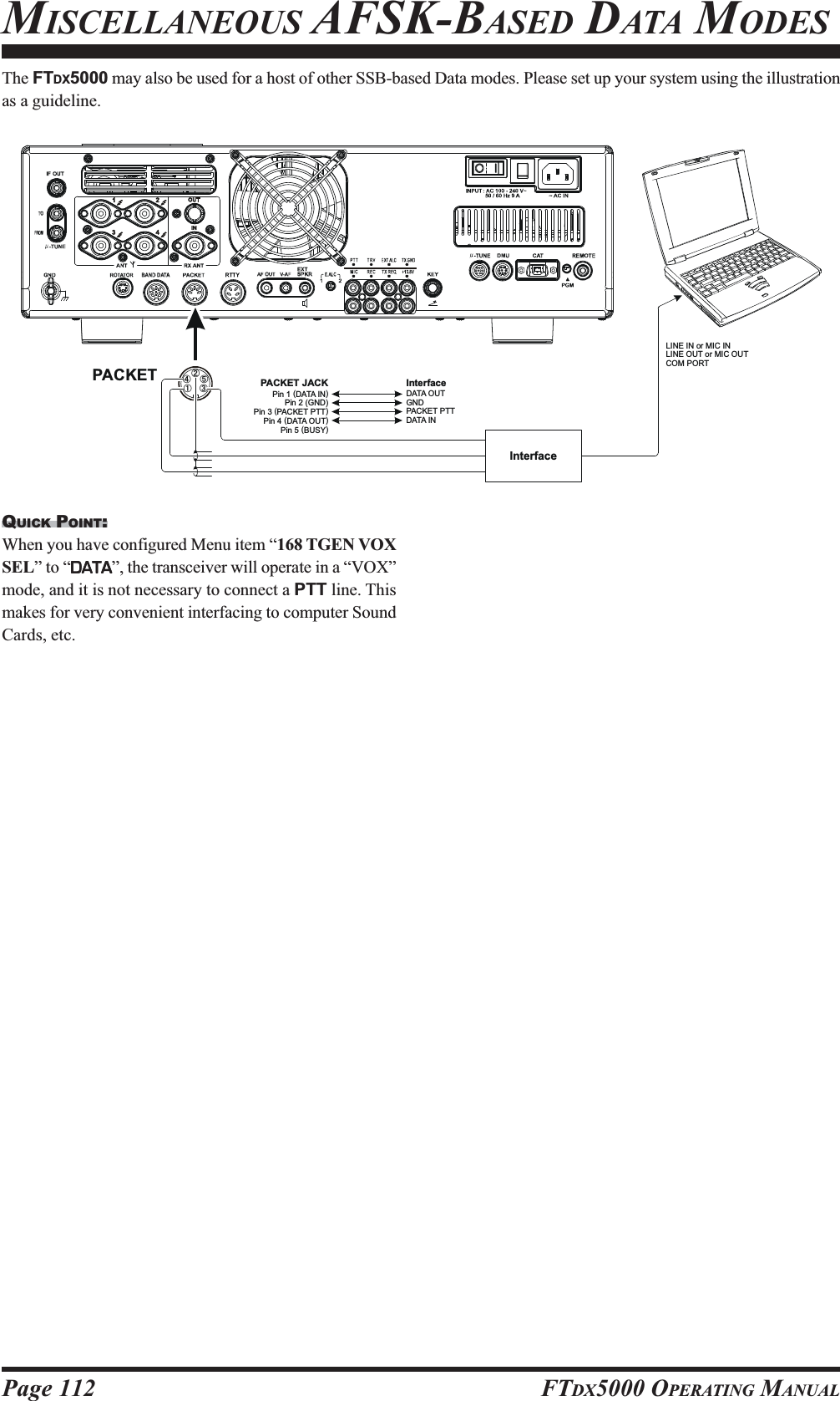
![Page 114 FTDX5000 OPERATING MANUALYou may connect an after-market transverter to the rear panel’s TRV jack. The output frequency is selectable from the 14,28, and 50 MHz, and the output is approximately –10 dBm (0.1 mW) at 50 Ohms.SETUP ABOUT THE TRANSVERTER OUTPUT TERMINAL1. Press the [MENU] button to enter the Menu mode.2. Rotate the (VFO-A)[SELECT] knob to select Menuitem “144 TUNE MY BAND”.3. Rotate the (VFO-B)[SELECT] knob to select the de-serving input frequency band of the transverter in menuitem (T14M OFFT14M OFFT14M OFFT14M OFFT14M OFF, T28M OFFT28M OFFT28M OFFT28M OFFT28M OFF, or T50M OFFT50M OFFT50M OFFT50M OFFT50M OFF ).4. Press the [ENT] button (one of the [BAND] button) tochange the parameter to “ON” (a “OFFOFFOFFOFFOFF” notation willreplace the “ONONONONON” notation).5. Rotate the (VFO-A)[SELECT] knob to select Menuitem “166 TGEN ETX-GND”.6. Rotate the (VFO-B)[SELECT] knob to set this Menuitem to “ENABLEENABLEENABLEENABLEENABLE” to enabling the rear panel’s TX GNDjack7. Press and hold in the [MENU] button for at least twoseconds to save the new setting and exit to normal op-eration.Setting the Transverter Frequency OffsetYou may set up the frequency display so that it shows theactual band on which your transverter is operating (insteadof the “IF” used by the transverter, which is the 28 MHzband on your FTDX5000).Example: Setting up the FTDX5000 display for use with a144 MHz Transverter1. Connect the 144 MHz transverter to the FTDX5000.2. Press the [MENU] button to enter the Menu mode.3. Rotate the (VFO-B)[SELECT] knob to select theMenu item which deserve the input frequency band ofthe transverter (036 GENE TRV 14M036 GENE TRV 14M036 GENE TRV 14M036 GENE TRV 14M036 GENE TRV 14M, 036 GENE TRV036 GENE TRV036 GENE TRV036 GENE TRV036 GENE TRV28M28M28M28M28M, or 036 GENE TRV 50M036 GENE TRV 50M036 GENE TRV 50M036 GENE TRV 50M036 GENE TRV 50M).4. Rotate the (VFO-B)[SELECT] knob so as to select“44MHz44MHz44MHz44MHz44MHz” on the display.5. Press and hold in the [MENU] button for at least twoseconds to save the new setting and exit.The “100 MHz” digit of the frequency is not displayed,so when you are operating on 2 meters and see “45MHz” on the frequency readout, this indicates “145MHz” instead.ADVICE:With the setup described above, tuning the actual operat-ing range of the FTDX5000 will correspond to transverter’soperating frequency of 144-145 MHz, with “44-45” beingdisplayed on the front panel of the transceiver.(VFO-B)[SELECT] Knob[MENU] Button(VFO-A)[SELECT] Knob[ENT] Button](https://usermanual.wiki/Yaesu-Musen/20361X60.Users-Manual-2/User-Guide-1211679-Page-56.png)