Yaesu Musen 20361X61 HF Transceiver with Scanning Receiver User Manual P65
Yaesu Musen Co., Ltd. HF Transceiver with Scanning Receiver P65
UserManual.wiki
>
Yaesu Musen
>
20361X61 User Manual
>
Users Manual 1
Contents
1.
Users Manual 1
2.
Users Manual 2
Users Manual 1
Navigation menu
Upload a User Manual
Namespaces
Wiki Guide
HTML
PDF
Info
Views
User Manual
Discussion / Help
Navigation

![Page 2 FTDX5000 OPERATING MANUALTABLE OF CONTENTSGeneral Description ..................................................... 1Accessories & Options ................................................. 4Supplied Accessories ............................................... 4Available Options ..................................................... 4Before You Begin ......................................................... 6Connecting AC Power .............................................. 6Extending the Front Feet .......................................... 6Adjusting the Main Tuning Dial Torque .................. 6Resetting the Microprocessor .................................. 7Resetting Memories (Only) ................................ 7Menu Resetting ................................................... 7Full Reset ............................................................ 7Installation and Interconnections ............................... 8Antenna Considerations ........................................... 8About Coaxial Cable ................................................ 8Grounding ................................................................ 9Connection of Antenna and Power Cables ............. 10Connection of Microphone and Headphone .......... 11Key, Keyer, and Computer-Driven KeyingInterconnections ..................................................... 12VL-1000 Linear Amplifier Interconnections .......... 13Interfacing to Other Linear Amplifiers ................... 14Plug/Connector Pinout Diagrams ............................ 15Front Panel Controls & Switches ............................. 16Display Indications .................................................... 30Rear Panel .................................................................. 33FH-2 Switches ............................................................ 36Basic Operation: Receiving on Amateur Bands ...... 37CLAR (Clarifier) Operation on Main (VFO-A) ..... 40LOCK ..................................................................... 41DIM ........................................................................ 41Operation on 60-Meter (5 MHz) Band(U.S. version only) ................................................. 41Convenience Features................................................ 42Dual Receive .......................................................... 42Using Headphones for Dual Receive ............... 43Sideband Diversity Reception .......................... 43Bandwidth Diversity Reception ....................... 44P.BACK (Audio Playback) fromMain (VFO-A) Receiver ........................................ 45“MY Bands” Operation .......................................... 46Band Stack Operation ............................................ 47C.S (Custom Switch) .............................................. 47Rotator Control Functions ...................................... 48More Frequency Navigation Techniques ............... 49Keyboard Frequency Entry .............................. 49Using the [(UP)]/[(DOWN)] Buttons ....... 49Using the UP/DOWN switches ofthe supplied MH-31B8 Hand Microphone ........ 49Receiver Operation (Front End Block Diagram) ... 50IPO (Intercept Point Optimization) ........................ 51ATT ........................................................................ 52RF Gain (SSB/CW/AM Modes) ............................ 53Advanced Interference-Suppression Features:RF Front End ............................................................. 54Using the VRF (Variable RF Front-end Filter) ...... 54Interference Rejection(Signals Off Frequency by Just a Few kHz) ............ 56R.FLT (Roofing Filters) ......................................... 56Interference Rejection (Signals within 3 kHz) ........ 58CONTOUR Control Operation .............................. 58IF SHIFT Operation ............................................... 60WIDTH (IF DSP Bandwidth) Tuning .................... 61Using IF Shift and Width Together ........................ 62IF Notch Filter Operation ....................................... 63Digital Noise Reduction (DNR) Operation ............ 64Digital Notch Filter (DNF) Operation ................... 64NARROW (NAR) One-Touch IF Filter Selection . 65IF Noise Blanker (NB) Operation .......................... 66Tools for Comfortable and Effective Reception ...... 67AGC (Automatic Gain Control) ............................. 67SLOPED AGC Operation ................................. 68Mute Feature (VFO-A Band) ................................. 69Adjustable Receiver Audio Filter ........................... 69SSB/AM Mode Transmission .................................... 70Using the Automatic Antenna Tuner ........................ 72ATU Operation ....................................................... 72About ATU Operation ............................................ 73Enhancing Transmit Signal Quality ......................... 74Parametric Microphone Equalizer ......................... 74Using the Speech Processor ................................... 76Adjusting the SSB Transmitted Bandwidth ........... 77Low- Distortion CLASS-A Operation .................... 78Transmitter Convenience Features .......................... 80Voice Memory ........................................................ 80VOX (Automatic TX/RX Switching using Voice Control) ............. 81MONITOR ............................................................. 81Split Operation Using the TX Clarifier .................. 82Split-Frequency Operation ..................................... 83VFO Tracking Feature ...................................... 83Quick Split Operation ....................................... 84](https://usermanual.wiki/Yaesu-Musen/20361X61.Users-Manual-1/User-Guide-1234776-Page-4.png)

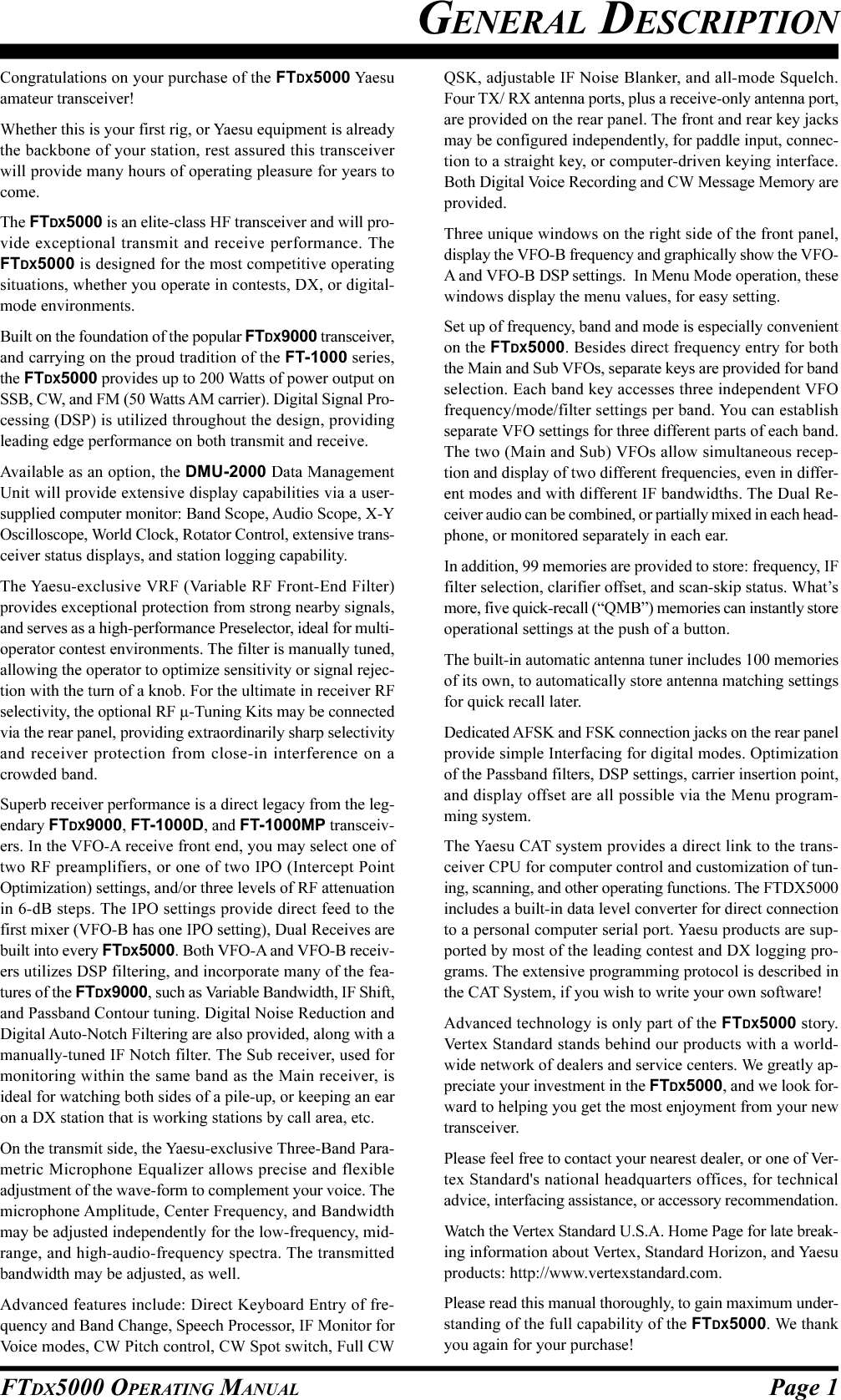
![Page 7FTDX5000 OPERATING MANUALRESETTING THE MICROPROCESSORRESETTING MEMORIES (ONLY)Use this procedure to reset (clear out) the previously storedMemory channels, without affecting any configurationchanges you may have made to the Menu settings.1. Press the front panel [POWER] switch to turn the trans-ceiver off.2. Press and hold in the [AM] button; while holding itin, press and hold in the front panel [POWER] switchto turn the transceiver on. Once the transceiver comeson, release the buttons.MENU RESETTINGUse this procedure to restore the Menu settings to theirfactory defaults, without affecting the memories you haveprogrammed.1. Press the front panel [POWER] switch to turn the trans-ceiver off.2. Press and hold in the [MENU] button; while holding itin, press and hold in the front panel [POWER] switchto turn the transceiver on. Once the transceiver comeson, release the buttons.FULL RESETUse this procedure to restore all Menu and Memory set-tings to their original factory defaults. All Memories willbe cleared out by this procedure.1. Press the front panel [POWER] switch to turn the trans-ceiver off.2. Press and hold in the [FAST] and [LOCK] buttons;while holding them in, press and hold in the front panel[POWER] switch to turn the transceiver on. Once thetransceiver comes on, release the switches.BEFORE YOU BEGIN[POWER] Switch [AM] Button[POWER] Switch [MENU] Button[POWER] Switch [FAST] / [LOCK] Button](https://usermanual.wiki/Yaesu-Musen/20361X61.Users-Manual-1/User-Guide-1234776-Page-9.png)
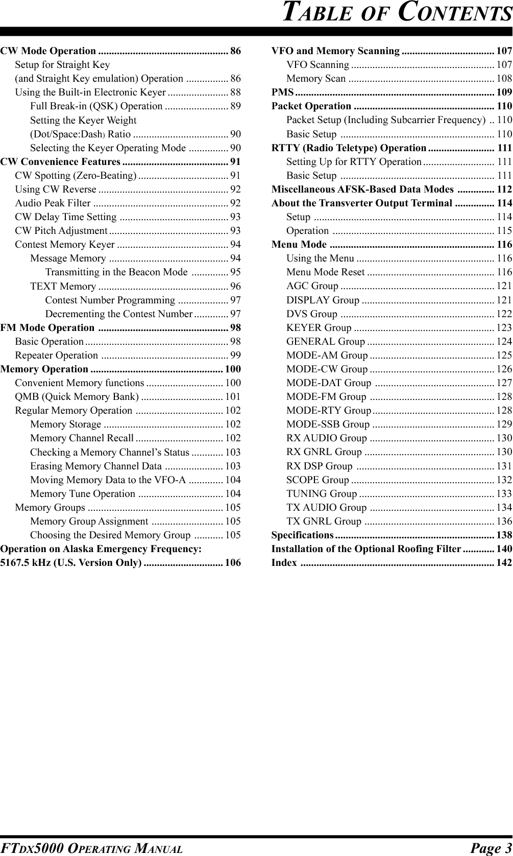
![Page 13FTDX5000 OPERATING MANUALANT 1ANT 2ANT 3ANT 4REMOTEONOFFBAND DATA 1BAND DATA 2GNDALC 2ALC 1PTT 2PTT 1INPUT 1INPUT 2CONTROLDC48V INANT~AC INANT 1ANT 2ANT 3INPUTBAND DATABAND-DATA 1GNDDC 48V INCONTROLBAND DATA Cable VL-1000 (Supplied with )VP-1000VP-1000TX REQEXT ALCBAND-DATA 2ALC 1ALC Cable (Supplied with VL-1000) CONTROL Cable (Supplied with VL-1000) ANTENNA Cable To ANTE NN AVL-1000 LINEAR AMPLIFIER INTERCONNECTIONSBe sure both the FTDX5000 and VL-1000 are turned off, then follow the installation recommendations contained in theillustration.NOTE:Refer to the VL-1000 Operating Manual for details regarding amplifier operation.Do not attempt to connect or disconnect coaxial cables when your hands are wet.INSTALLATION AND INTERCONNECTIONSAbout the CONTROL CableThe VL-1000 may be operated with theFTDX5000 whether or not the CONTROL Cableis connected; however, the CONTROL Cableallows you to tune up the amplifier automaticallyby just pressing the [F SET] or [TUNE] key onthe VL-1000, to transmit a carrier for tuning pur-poses.To link the FTDX5000 and VL-1000 Powerswitches, set the VL-1000 REMOTE switch tothe “ON” position.](https://usermanual.wiki/Yaesu-Musen/20361X61.Users-Manual-1/User-Guide-1234776-Page-15.png)
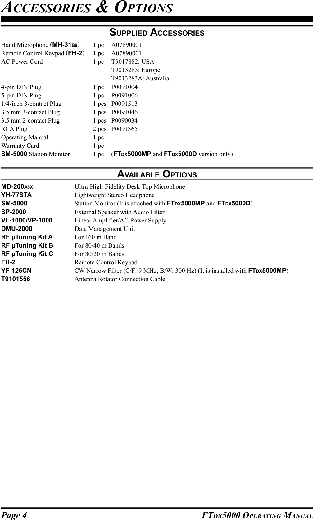
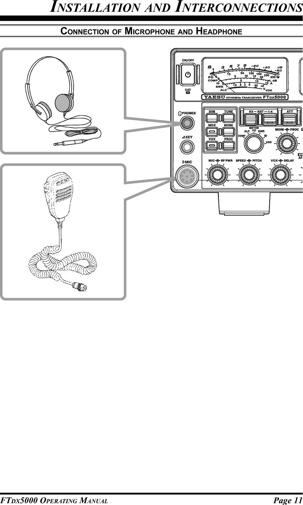
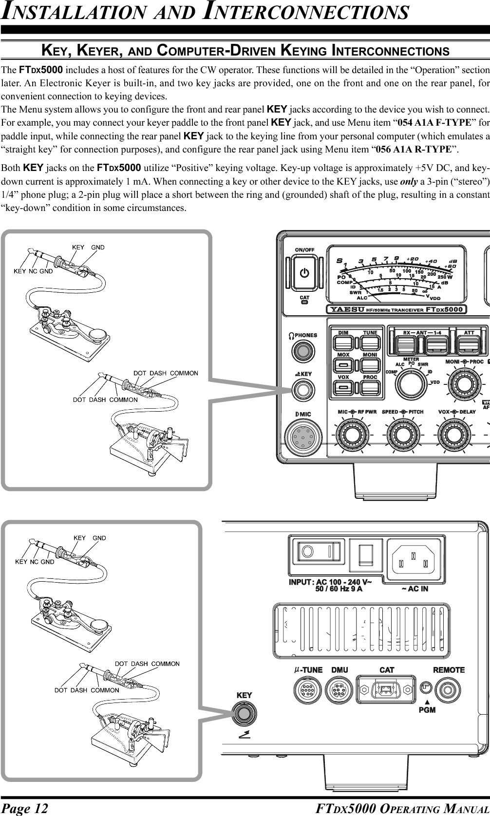
![Page 16 FTDX5000 OPERATING MANUAL[POWER] SwitchPress this switch in for two seconds to turn the trans-ceiver on. Alternately, press this switch for two sec-onds to turn the transceiver off. If the rear panel [MAINPOWER] switch is set to the “O” (OFF) position, thefront panel [POWER] switch will not function.ADVICE:If you press this switch briefly while the transceiveris turned on, the transceiver audio will be mutedfor three seconds.This is the actual power On/Off switch for turningthe transceiver on. In the MP version, when the rearpanel [MAIN POWER] switch is set to the “I”(ON) position, power is supplied to the OCXO tostabilize the reference oscillator. The remainder ofthe transceiver is set in a “stand-by” mode. For fur-ther information on the rear panel [MAIN POWER]switch, please see the discussion on page 35.CAT IndicatorThis LED indicator will flash red when serial CAT com-mand signals are being exchanged.ADVICE:You may disable the LED CAT command signal flash-ing function, via Menu item “035 GENE CAT IND.”See page 124 for details.PHONES JackA 1/4-inch, 3-contact jack accepts either monaural orstereo headphones with 2- or 3-contact plugs. When aplug is inserted, the loudspeaker is disabled. With ste-reo headphones such as the optional YH-77STA, youcan monitor both VFO-A and VFO-B receiver chan-nels at the same time during Dual Receive operation.NOTE:When wearing headphones, we recommend that youturn the AF Gain levels down to their lowest settingsbefore turning power on, to minimize the impact of anyaudio “pops” on your hearing during switch-on.KEY JackThis 1/4-inch, 3-contact jack accepts a CW key or keyerpaddles (for the built-in electronic keyer), or outputfrom an external electronic keyer. Pinout is shown onpage 15. Key up voltage is 5 V, and key down currentis 1 mA. This jack may be configured for keyer, “Bug,”“straight key,” or computer interface keying operationvia Menu item “057 A1A F-TYPE” (see page 126).There is another KEY jack on the rear panel, and itmay be configured independently for Internal Keyeror pseudo-straight-key operation.NOTE:You cannot use a 2-contact plug in this jack (to do soproduces a constant “key down” condition).Microphone ConnectorThis 8-pin jack accepts input from a microphone uti-lizing a traditional YAESU HF-transceiver pinout.FRONT PANEL CONTROLS & SWITCHES](https://usermanual.wiki/Yaesu-Musen/20361X61.Users-Manual-1/User-Guide-1234776-Page-18.png)
![Page 17FTDX5000 OPERATING MANUAL[DIM] SwitchPress this button to lower the illumination intensity ofthe analog meter and the frequency display. Press itonce more to restore full brightness.ADVICE:The following Menu items allow you to configure thedimming levels of each display independently to cus-tomize the brightness levels.008 DISP DIM MTR: for analog meter009 DISP DIM VFD: for frequency display010 DISP DIM OLE:SUB DISPLAY windows011 DISP DIM ELCD: for Spectrum Scope displayof the optional SM-5000 Sta-tion Monitor[MOX] SwitchPressing this button engages the PTT (Push to Talk)circuit, to activate the transmitter. The LED inside thebutton will glow red during transmit. It must be turnedoff (the red LED will be off) for reception. This buttonreplicates the action of the Push to Talk (PTT) switchon the microphone. When engaging the [MOX] buttonor otherwise starting a transmission, be certain you haveeither an antenna or 50-Ohm dummy load connectedto the selected Antenna jack.[VOX] SwitchThis button enables automatic voice-actuated transmit-ter switching in the SSB, AM, and FM modes. Whileactivated, the LED inside the button glows red. Properadjustment of the front panel [VOX] and [DELAY]knobs will make hands-free voice-actuated operationpossible.[TUNE] SwitchThis is the on/off switch for the FTDX5000’s Auto-matic Antenna Tuner.Pressing this button briefly, places the antenna tuner inline between the transmitter final amplifier and the an-tenna jack (The “ ” icon will appear in the dis-play). Reception is not affected.Pressing this button for 1/2 second, while receiving inan amateur band, activates the transmitter for a fewseconds while the automatic antenna tuner rematchesthe antenna system impedance for minimum SWR. Theresulting setting is automatically stored in one of theantenna tuner’s 100 memories, for instant automaticrecall later when the receiver is tuned near the samefrequency.Pressing this button briefly, while the Tuner is engaged,will take the Automatic Antenna tuner out of the trans-mit line.NOTE:A signal is being transmitted while the tuner is match-ing the antenna impedance. Therefore, be certain thereis a dummy load or antenna connected to the selectedantenna jack before initiating the tuning sequence.[MONI] (Monitor) SwitchThis button enables the transmit monitor in all modes.While activated, the “ ” icon appears in the dis-play. Use the [MONI] knob to adjust the Monitor level.ADVICE:The Monitor is highly useful for making adjustmentsto the Parametric Equalizer, or other voice character-istic adjustments, while listening with headphones. Thevoice quality heard in the headphones is a “natural”reproduction of the transmitted audio.[PROC] (Processor) SwitchThis button enables the Speech Processor for SSBtransmission. While activated, the “ ” icon appearsin the display. Adjustment of the Processor level is ac-complished using the [PROC] knob.ADVICE:The Speech Processor uses a compression techniqueto increase the average power output. However, ifthe [PROC] knob is advanced too far, the increasein compression becomes counter-productive, andintelligibility will suffer. We recommend that youmonitor the sound of your signal using the Monitor(with headphones).When the optional DMU-2000 Data ManagementUnit is connected, you may use the Audio Scope/Oscilloscope function to help you adjust the set-ting of the Speech Processor compression level foroptimum performance with your voice and micro-phone.[RX ANT] SwitchPress this button to use an antenna connected to theRX ANT jack on the rear panel for receive.The “RX” icon appears in the display when the RXANT is used.[ANT 1-4] SwitchMove this knob up or down to conveniently select oneof the four antenna jacks on the rear panel. The se-lected antenna jack is indicated in the ANT column ofthe Block Diagram Display.ADVICE:Press this knob in briefly to quickly select the ANT 1jack.FRONT PANEL CONTROLS & SWITCHESANTENNA SWITCH(VFO-A)ANTENNA SWITCH(VFO-B)RX ANTENNA SWITCH(VFO-B)RX ANTENNA SWITCH(VFO-A)TX/RX RELAY Transmitter SectionVFO-A ReceiverVFO-B ReceiverBPFANT “1”ANT “3”ANT “2”ANT “4”RX ANTRX OUTDividerSEPARATESEPARATE](https://usermanual.wiki/Yaesu-Musen/20361X61.Users-Manual-1/User-Guide-1234776-Page-19.png)
![Page 18 FTDX5000 OPERATING MANUALFRONT PANEL CONTROLS & SWITCHES[ATT] SwitchMove this knob up or down to select the degree ofAttenuation to be applied to the receiver input.Available selections are “–6 dB”, “–12 dB”, “–18 dB”,or “OFF”. The selected attenuation level appears inthe ATT column of the Block Diagram Display.ADVICE:Press this knob in briefly, to quickly turn the at-tenuation level off.The Attenuator may be used in conjunction withthe [IPO] switch to provide additional gain reduc-tion when an extremely strong signal is being re-ceived.[IPO] (INTERCEPT POINT OPTIMIZATION) SwitchMove this knob up or down to select the optimum frontend characteristics of the receiver circuit. Availableselections are “AMP 1”, “AMP 2”, “IPO 1”, or “IPO2”.Normally, IPO is set to “AMP1”. If you want to in-crease the sensitivity, use “AMP2”. When set to“IPO1”, the IPO performance of the receivers is im-proved. When set to “IPO2”, the RF preamplifier isbypassed, yielding direct feed to the first mixer. As aresult, the IPO is improved more.ADVICE:Press this knob in briefly to quickly select the“AMP1” IPO setting.“IPO 2” can not be selected for VFO-B.[R.FLT] SwitchMove this knob up or down to select the bandwidth ofthe first IF Roofing Filter. Available selections are “300Hz”, “600 Hz”, “3 kHz”, “6 kHz”, “15 kHz”, or“AUTO” (“300 Hz” and “600 Hz” are available onlyin VFO-A. The “300 Hz” filter is optional, except inthe MP version). The selected bandwidth appears inthe R.FLT column of the Block Diagram Display.ADVICE:Press this knob in briefly to quickly select “AUTO”.Because the roofing filter is in the first IF, the pro-tection it provides against interference is quite sig-nificant. When set to “AUTO”, the SSB bandwidthis 6 kHz, CW is 3 kHz, and FM/RTTY are 15 kHz.However, on a crowded SSB band, you may wishto select the 3 kHz filter, for the maximum possibleinterference rejection.](https://usermanual.wiki/Yaesu-Musen/20361X61.Users-Manual-1/User-Guide-1234776-Page-20.png)
![Page 19FTDX5000 OPERATING MANUALFRONT PANEL CONTROLS & SWITCHES[AGC] SwitchMove this knob up and down to select the receiver AGCcharacteristics (receiver-recovery time). Available se-lections are FAST, MID, SLOW, or AUTO, and theselected receiver-recovery time appears in the AGCcolumn of the Block Diagram Display.Hold this knob up or down for two seconds to disablethe AGC (for testing or weak-signal reception).ADVICE:Press this knob in briefly to quickly select “AUTO”.If the AGC is disabled by holding the [AGC] knobup or down, the S-meter will no longer deflect. Ad-ditionally, you will likely encounter distortion onstronger signals, as the IF amplifiers and the fol-lowing stages may be overloaded.[METER] SwitchThis control switch determines the function of the meterduring transmission.COMP: Indicates the speech compression level (SSBmode only).ALC: Indicates the relative ALC voltage.PO: Indicates the average power output level.SWR: Indicates the Standing Wave Ratio (Forward:Reflected).ID: Indicates the final amplifier drain current.VDD: Indicates the final amplifier drain voltage.[MONI] [PROC] Knobs[MONI] KnobThe inner [MONI] knob adjusts the audio level ofthe transmit RF monitor during transmission (rela-tive to the AF GAIN control), when activated bythe [MONI] button.[PROC] KnobThe outer [PROC] knob sets the compression (in-put) level of the transmitter Speech Processor inthe SSB, AM, and FM modes, when activated bythe [PROC] button.ADVICE:The relative compression level of the Speech Pro-cessor will show for 3-seconds in the lower rightcorner of the Main Display whenever the outer[PROC] knob is turned.Alternately, the 3-second display feature may bechanged to show in the SUB DISPLAY-III win-dow via Menu item “018 DISP INDI”. Addition-ally, you may disable the 3-second display featurevia Menu item “017 DISP LVL IND” See page122 for details.(VFO-B) [NB][SQL] Knobs[NB] KnobThe inner [NB] knob adjusts the noise blankinglevel when the VFO-B (analog) IF noise blanker isactivated by pressing the [NB] button.[SQL] KnobThe outer [SQL] knob sets the signal level thresh-old at which the VFO-B receiver audio is muted, inall modes. The squelch is very useful during localrag-chews, to eliminate noise between incomingtransmissions. This control is normally kept fullycounter-clockwise (off), except when scanning andduring FM operation.(VFO-A) [NB] [SQL] Knobs[NB] KnobThe inner [NB] knob adjusts the noise blankinglevel when the VFO-A (analog) IF noise blanker isactivated by pressing the [NB] button.[SQL] KnobThe outer [SQL] knob sets the signal level thresh-old at which the VFO-A receiver audio is muted, inall modes. The squelch is very useful during localrag-chews, to eliminate noise between incomingtransmissions. This control is normally kept fullycounter-clockwise (off), except when scanning andduring FM operation.](https://usermanual.wiki/Yaesu-Musen/20361X61.Users-Manual-1/User-Guide-1234776-Page-21.png)
![Page 20 FTDX5000 OPERATING MANUALFRONT PANEL CONTROLS & SWITCHES[MIC] [RF PWR] Knobs[MIC] KnobThe inner [MIC] knob adjusts the microphone in-put level for (non-processed) SSB transmission.ADVICE:Adjust the MIC Gain while speaking in a some-what-louder-than-normal voice. Watch the ALClevel and adjust the MIC Gain so that the ALCindication reaches just to the right edge of thescale. Then, when you speak in a normal voicelevel, you will not over-driving the mic ampli-fier stage.The relative Microphone Gain level will showfor 3-seconds in the lower right corner of theMain Display whenever the inner [MIC] knobis turned.Alternately, the 3-second display feature maybe changed to show in the SUB DISPLAY-IIIwindow via Menu item “018 DISP INDI”. Ad-ditionally, you may disable the 3-second dis-play feature via Menu item “017 DISP LVLIND” See page 122 for details.[RF PWR] KnobThe outer [RF PWR] knob is the main RF Poweroutput control for the transceiver. It is active in alloperating modes. Clockwise rotation increases thepower output. Adjust this control for the desiredpower output from the FTDX5000.ADVICE:The RF Power output will show for 3 seconds inthe lower right corner of the Main Display when-ever the outer [RF PWR] knob is turned.Alternately, the 3-second display feature may bechanged to show in the SUB DISPLAY-III win-dow via Menu item “018 DISP INDI”. Addition-ally, you may disable the 3-second display featurevia Menu item “017 DISP LVL IND” See page122 for details.](https://usermanual.wiki/Yaesu-Musen/20361X61.Users-Manual-1/User-Guide-1234776-Page-22.png)
![Page 21FTDX5000 OPERATING MANUALFRONT PANEL CONTROLS & SWITCHES[SPEED] [PITCH] Knobs[SPEED] KnobThe inner [SPEED] knob adjusts the keying speedof the internal CW keyer (4 ~ 60 WPM). Clock-wise rotation increases the sending speed.The keying speed will show for 3 seconds in thelower right corner of the Main Display while the[KEYER] button is held depressed for more thanone second.ADVICE:The keying speed will show for 3 seconds in thelower right corner of the Main Display wheneverthe outer [SPEED] knob is turned.Alternately, the 3-second display feature may bechanged to show in the SUB DISPLAY-III win-dow via Menu item “018 DISP INDI”. Addition-ally, you may disable the 3-second display featurevia Menu item “017 DISP LVL IND” See page122 for details.[PITCH] KnobThe outer [PITCH] knob selects your preferred CWtone pitch (from 300 ~ 1050 Hz, in 50 Hz incre-ments). The TX sidetone, the receiver IF passband,and the display offset from the BFO (carrier) fre-quency are all affected simultaneously. The Pitchcontrol setting also affects the operation of the CWTuning Indicator, as the center frequency of the CWTuning Indicator will follow the setting of this con-trol.ADVICE:The CW tone pitch frequency will show for 3 sec-onds in the lower right corner of the Main Displaywhenever the outer [SPEED] knob is turned.Alternately, the 3-second display feature may bechanged to show in the SUB DISPLAY-III win-dow via Menu item “018 DISP INDI”. Addition-ally, you may disable the 3-second display featurevia Menu item “017 DISP LVL IND” See page122 for details.[VOX] [DELAY] Knobs[VOX] KnobThe inner [VOX] knob sets the level of microphoneaudio needed to activate the transmitter during voiceoperation when the [VOX] switch is actuated.[DELAY] KnobThe outer [DELAY] knob sets the hang time of theVOX circuit for voice operation, and the keyingdelay for CW operation.For voice operation, this knob sets the hang time,between the moment you stop speaking, and thetime the transmit is switched back to receive. Forsmooth operation, adjust the VOX so the transmitswitches to receive when your comments haveended.For CW, this knob sets the automatic transmit toreceive keying delay for “Semi-break-in” operation.Adjust this just long enough to prevent the receiverfrom being restored during word spaces at yourpreferred sending speed.ADVICE:The hang time of the VOX circuit will show for 3seconds in the lower right corner of the Main Dis-play whenever the outer [SPEED] knob is turned.Alternately, the 3-second display feature may bechanged to show in the SUB DISPLAY-III win-dow via Menu item “018 DISP INDI”. Addition-ally, you may disable the 3-second display featurevia Menu item “017 DISP LVL IND” See page122 for details.(VFO-B)[AF GAIN] [RF GAIN] Knobs[AF GAIN] KnobThe inner [AF GAIN] knob sets the audio level ofthe VFO-B receiver. Typically, you will operate withthis control set between the 9 o’clock and 10 o’clockpositions.[RF GAIN] KnobThe outer [RF GAIN] knob sets the gain of the RFand IF amplifier stages of the VFO-B receiver. Thiscontrol is normally left in the fully clockwise posi-tion.(VFO-A) [AF GAIN] [RF GAIN] Knobs[AF GAIN] KnobThe inner [AF GAIN] knob sets the audio level ofthe VFO-A receiver. Typically, you will operate withthis control set between the 9 o’clock and 10 o’clockpositions.[RF GAIN] KnobThe outer [RF GAIN] knob sets the gain of the RFand IF amplifier stages of the VFO-A receiver. Thiscontrol is normally left in the fully clockwise posi-tion.](https://usermanual.wiki/Yaesu-Musen/20361X61.Users-Manual-1/User-Guide-1234776-Page-23.png)
![Page 22 FTDX5000 OPERATING MANUALFRONT PANEL CONTROLS & SWITCHES[A], [B] SwitchesPressing the [A] or [B] button will illuminate the re-spective switch, and allow adjustment of the majorfunctions (such as mode and band selection etc) on theVFO-A or VFO-B receiver. Usually, the [A] button willglow red, and the VFO-A functions may be adjusted.Similarly, pressing the [B] button will cause its indica-tor glow orange, signifying the VFO-B functions maybe adjusted.ADVICE:The [A]/[B] switches affect the following functions:[RX ANT] switch[ANT 1-4] switch[ATT] switch[IPO] switch[R.FLT] switch[AGC] switch[NAR] switch[BAND] switches[MODE] switches[NB] switch[RX ANT] switchQMB (Quick Memory Bank) Switches[STO] (Store) ButtonPressing this button, copies the operating informa-tion for frequency, mode, and bandwidth, into con-secutive QMB Memories. Repeater shift/direction,frequency and CTCSS functions, are also copiedin the FM mode.[RCL] (Recall) ButtonPressing this button recalls one of the five QuickMemory Bank memories for operation.[NAR] (Narrow) SwitchThis button is used to set the DSP (digital) filters tonarrow bandwidths. The default values are as follows::You may enable the [WIDTH] knob to adjust thebandwidth.OFF2.4 kHz(1.8 kHz - 4.0 kHz / 16 steps)2.4 kHz(500 Hz - 2.4 kHz / 7 steps)500 Hz(500 Hz - 2.4 kHz / 7 steps)500 Hz(500 Hz - 2.4 kHz / 7 steps)25 kHz(±5.0 kHz Deviation)9 kHz25 kHz(±5.0 kHz Deviation)ON1.8 kHz(200 Hz - 1.8 kHz / 9 steps)500 Hz(50 Hz - 500 Hz / 10 steps)300 Hz(50 Hz - 500 Hz / 10 steps)300 Hz(50 Hz - 500 Hz / 10 steps)12.5 kHz(±2.5 kHz Deviation)6 kHz12.5 kHz(±2.5 kHz Deviation)MODELSB/USBCWRTTY(LSB)PKT(LSB/USB)PKT(FM)AMFMNAR SWITCH](https://usermanual.wiki/Yaesu-Musen/20361X61.Users-Manual-1/User-Guide-1234776-Page-24.png)
![Page 23FTDX5000 OPERATING MANUALFRONT PANEL CONTROLS & SWITCHES[SPLIT] SwitchPress this button briefly to activate split frequency op-eration between the VFO-A receiver and the VFO-B,transmit. Press and hold in this button for two secondsto engage the “Quick Split” feature, whereby VFO-Bwill automatically be set to a frequency 5 kHz higherthan the VFO-A frequency with the same operatingmode, and the transceiver will be placed in the Splitmode.[TXW] (TX Watch) SwitchPress and hold this button to monitor the transmit fre-quency when split frequency operation is engaged.Release the button to return to normal operation.[CLASS-A] SwitchPress this button to engage the Class-A transmit capa-bility. The power output will be reduced to a maxi-mum of 75 Watts. However, Class-A operation pro-vides an ultra-clean SSB waveform. When Class-A op-eration is engaged, the “CLASS-A” icon appears inthe display. Press this button once more to return toClass-AB operation at a maximum power output of 200Watts; the “CLASS-A” icon disappears to confirmClass-AB operation.ADVICE:You may adjust the bias level between “Class-AB” and“Class-A” via Menu item “169 TGEN BAIS”. Seepage 136 for details.[C.S] SwitchPress this button briefly to recall a favorite Menu Se-lection directly.To assign a Menu selection as the short-cut, press the[MENU] button to enter the Menu, then select the Menuitem. Now press and hold in the [C.S] button for twoseconds to lock the selected Menu item as the short-cut.(VFO-A)[RX] Indicator/SwitchPress this button to engage the VFO-A receiver; thebutton will glow green when the VFO-A receiver isactive.When the VFO-A receiver is active, pressing this but-ton briefly will mute the receiver, and the indicator willblink. Pressing the button once more will restore re-ceiver operation, and the indicator will glow greensteadily.(VFO-A)[TX] Indicator/SwitchWhen this button is pressed, the button indicator willglow red and the transmitter frequency and mode willbe controlled by VFO-A (subject to any Clarifier off-set, of course).ADVICE:If this indicator is not illuminated, it means that VFO-B TX has been selected (In this case, The VFO-B TXindicator will glow red and the transmitter frequencyand mode will be controlled by VFO-B).OPERATING MODELSB/USB/CW/RTTY/PKT(SSB)AM/FM/PKT(FM)Numbers in parentheses indicate steps when the [FAST] button is On.1 STEP10 Hz (100 Hz)100 Hz (1 kHz)1 DIAL ROTATION10 kHz (100 kHz)100 kHz (1 MHz)Main Tuning Dial KnobThis large knob adjusts the operating frequency ofVFO-A or a recalled memory. Clockwise rotation ofthe knob increases the frequency. Default tuning in-crements are 10 Hz (100 Hz in AM and FM modes);when the [FAST] button is pressed, the tuning stepsincrease. The available steps are:ADVICE:The tuning steps for the Main Tuning Dial knobare set, at the factory, to 10 Hz per step. Via Menuitem “142 TUN DIAL STEP”, however, you maychange this setting from 10 Hz to 5 Hz or 1 Hzinstead. When the [FAST] button is pressed, thetuning step change to 100 Hz.You may lock the Main Tuning Dial knob in theAM and FM mode via Menu items “147 TUN AMD.LCK” and “148 TUN FM D.LCK”.[FAST] SwitchPressing this button will change the VFO-A tuningstep to 100 Hz.When this function is activated, the “ ” icon ap-pears in the display.[LOCK] SwitchThis button toggles locking of the Main Tuning Dialknob, to prevent accidental frequency changes. Whenthe button is active, the Main Tuning Dial knob canstill be turned, but the VFO-A frequency will notchange, and the “ ” icon appears in the display.[BAND] KeysThese buttons allow one-touch selection of the desiredamateur band (1.8 ~ 50 MHz).What’s more, these buttons may be used for direct en-try of a desired operating frequency during VFO op-eration.[MODE] SwitchesPressing one of these buttons, selects the operatingmode. Repeated presses of a particular switch willtoggle to the alternate mode, or step through the avail-able selections, as shown in the chart below.SWITCHLSBUSBCWAM/FMRTTYPKTVARIABLE MODE SELECTIONLSBUSBCW (LSB) CW (USB)AM FMRTTY (LSB) RTTY (USB)PKT (LSB)PKT (USB)PKT (FM) .....](https://usermanual.wiki/Yaesu-Musen/20361X61.Users-Manual-1/User-Guide-1234776-Page-25.png)
![Page 24 FTDX5000 OPERATING MANUAL[AB] SwitchPress this button briefly to transfer data from the VFO-A frequency (or a recalled memory channel) to VFO-B, overwriting any previous contents in VFO-B. Usethis button to set both VFO-A and VFO-B receivers tothe same frequency and mode.[AB] SwitchPressing this button briefly, exchanges the contents ofthe VFO-A (or a recalled memory channel) and theVFO-B.[V/M] SwitchThis button toggles VFO-A receiver operation betweenthe memory system and the VFO. Either “ ” or“” will be displayed under the main frequencydisplay field to indicate the current selection. If youhave tuned off of a Memory channel frequency (MT),pressing this button returns the display to the originalmemory contents (MR), and pressing it once more re-turns operation to VFO-A (no icon).[MA] SwitchPress this button briefly, to display the contents of thecurrently-selected memory channel for three seconds.Holding this button in for 2 seconds copies the datafrom the currently-selected memory to VFO-A, as twobeeps sound. Previous data in VFO-A will be over-written.[AM] SwitchPressing and holding in this button for 1/2 second (un-til the double beep), copies the current operating datafrom VFO-A into the currently selected memory chan-nel, overwriting any previous data stored there. Seepage 102 for details.Also, pressing and holding in this button after recall-ing a memory, without first retuning, causes the memorychannel to be “masked,” and repeating the process re-stores the masked memory.[MENU] SwitchThis button is used to access the Menu system, for con-figuring various transceiver characteristics. Menu op-eration is described in detail, in this manual, begin-ning on page 116.IMPORTANT NOTE:Pressing this button briefly activates the Menu, andthe Menu items will appear on the SUB DISPLAYwindows. Once you are finished, you must press andhold in the [MENU] button for two seconds to saveany configuration changes (briefly press the [MENU]button to exit without saving the changes).FRONT PANEL CONTROLS & SWITCHES](https://usermanual.wiki/Yaesu-Musen/20361X61.Users-Manual-1/User-Guide-1234776-Page-26.png)
![Page 25FTDX5000 OPERATING MANUAL[NB] SwitchThis button turns the IF Noise Blanker on and off.Press this button briefly to reduce a short-duration pulsenoise; the “ ” icon will appear in the display.Press this button once more to reduce a longer-dura-tion man-made pulse noise; the “ ” icon will appearat the right of the “ ” icon.Press this button again to disable the noise blanker;the “ ” and “ ” icon will disappear.[KEYER] SwitchThis button toggles the internal CW keyer on and off.While activated, the “ ” icon appears in the dis-play. The keyer sending speed is adjusted via the frontpanel [SPEED] knob, and the CW Hang Time is ad-justed via the front panel [DELAY] knob.ADVICE:When this button is held for more than one second, thekeying speed will be displayed in the lower right cor-ner of the Main Display until the button is released.Alternately, the 3-second display feature may bechanged to show in the SUB DISPLAY-III windowvia Menu item “018 DISP INDI”. See page 122 fordetails.[SPOT] SwitchThis button turns on the CW receiver spotting tone; bymatching the SPOT tone to that of the incoming CWsignal (precisely the same pitch), you will be “zerobeating” your transmitted signal with the frequency ofthe other station.ADVICE:The offset tone frequency will be displayed in the lowerright corner of the Main Display when this button ispressed.Alternately, the 3-second display feature may bechanged to show in the SUB DISPLAY-III windowvia Menu item “018 DISP INDI”. See page 122 fordetails.[BK-IN] SwitchThis button turns the CW break-in capability on andoff. While the CW break-in is activated, the “ ”icon appears in the display.[(DOWN)]/[(UP)] SwitchesThese buttons adjust the operating frequency of theVFO or a recalled memory in 100 kHz steps.SUB DISPLAY-IThis OLED (Organic Light Emitting Diode) displayshows the VFO-B frequency, and it indicates the MenuList while the Menu Mode is active.[RX CLAR(FAST)] SwitchThe function of this button differs with the setting ofthe [A/B] button (described later).When the LED in the [A/B] button is turned off, press-ing this button activates the RX Clarifier, to allow off-setting the VFO-A receiving frequency temporarily.Press this button once more to return the Main receiverto the frequency shown on the main frequency displayfield; the Clarifier offset will still be present, though,in case you want to use it again. To cancel the Clarifieroffset, press the [CLEAR] button.When [A/B] button glows orange, pressing this but-ton will change the VFO-B tuning step to 100 Hz.When this function is activated, the “ ” icon ap-pears in the display.[CLEAR] SwitchPressing this button clears out any frequency offset youhave programmed into the Clarifier register (therebysetting the offset to “Zero”).[TX CLAR/LOCK] SwitchThe function of this button is changed by the setting ofthe [A/B] button (described later).When the [A/B] button is turned off, pressing the [TXCLAR/LOCK] button activates the TX Clarifier, toallow offsetting the VFO-A transmit frequency tempo-rarily. Press the button once more to return the trans-mitter to the VFO-A frequency shown on the main fre-quency display field; the Clarifier offset will still bepresent, though, in case you want to use it again. Tocancel the Clarifier offset, press the [CLEAR] button.When the [A/B] button glows orange, the [TX CLAR/LOCK] button toggles locking of the [CLAR(VFO-B)] knob, to prevent accidental frequency changes.When the lock is active, the [CLAR(VFO-B)] knobcan still be turned, but the VFO-B frequency will notchange, and the “ ” icon appears in the display.FRONT PANEL CONTROLS & SWITCHES](https://usermanual.wiki/Yaesu-Musen/20361X61.Users-Manual-1/User-Guide-1234776-Page-27.png)
![Page 26 FTDX5000 OPERATING MANUAL[CLAR/GRP] SwitchThis button has two functions.Press this button briefly, the [CLAR/VFO-B] knobwill be enabled as an “offset tuning” control to allowtuning away from the VFO-A frequency, and the[CLAR/GRP] button will glow red.Pressing and holding this button for one second, al-lows you to select the memory group using the[CLAR(VFO-B)] knob, and the [CLAR/GRP] but-ton will glow yellow.[BAND(MCH)] SwitchThis button has two functions.Pressing this button briefly, enables the [CLAR(VFO-B)] knob to select the VFO-A operating Amateur Band.The [CLAR/GRP)] button glows red.Pressing and holding this button for one second, al-lows you to select the memory channel using the[CLAR(VFO-B)] knob, and the [CLAR/GRP] but-ton is glows yellow.[A/B] SwitchThis button switches the actions of the [CLAR(VFO-B)] knob between VFO-A and VFO-B.Pressing this button once causes the button to glowsyellow; in this case, rotation of the [CLAR(VFO-B)]knob affects operation on VFO-B (tuning, etc.). Press-ing this button once more causes the button to turn off;in this instance, rotation of the [CLAR(VFO-B)] knobaffects operations associated with the VFO-A (Clari-fier function, etc.).(VFO-B)[RX] Indicator/SwitchThis is the button that turns the VFO-B receiver “On”and “Off”. When the VFO-B receiver is active, thebutton will glow green. Pressing this button again willdisable VFO-B receiver, and the imbedded green LEDwill turn off.(VFO-B)[TX] Indicator/SwitchThis button turns the VFO-B transmitter “On” and“Off”. When this button is pressed, it will glow redand VFO-B will control the transmitter frequency andmode. Pressing this button once more will transfer fre-quency/mode control back to VFO-A, and the red LEDin the button will turn off.[CLAR(VFO-B)] KnobThe function of this knob differs according to the set-tings of the three switches located above the knob. Seethe next page for details.SUB DISPLAY-IIThis OLED (Organic Light Emitting Diode) displayshows the characteristics of the VFO-A receiver DSPfunctions selected by five of the buttons located belowof this display. The (VFO-A)[SELECT] knob locatedbelow this window is an adjustment knob for the func-tion displayed in this window. Alternately, when theMenu Mode is activated, this OLED displays the se-lected Menu item.FRONT PANEL CONTROLS & SWITCHES](https://usermanual.wiki/Yaesu-Musen/20361X61.Users-Manual-1/User-Guide-1234776-Page-28.png)
![Page 27FTDX5000 OPERATING MANUALFRONT PANEL CONTROLS & SWITCHESClarifier OperationWhen the [CLAR/GRP] button is pressed briefly, theimbedded LED in the button will glow red, and the[CLAR(VFO-B)] knob may be used to program anoffset of up to ± 9.999 kHz from the VFO-A frequency.However, this offset is only applied to the receive ortransmit frequency if the [RX CLAR/FAST] buttonand/or [TX CLAR/LOCK] button, respectively, havebeen pushed.To apply the programmed frequency offset to the Re-ceive frequency, press the [RX CLAR/FAST] buttonbriefly. To return to the VFO-A frequency, without theoffset, press the [RX CLAR/FAST] button once more.To apply the programmed frequency offset to the Trans-mit frequency, press the [TX CLAR/LOCK] buttonbriefly. To return the transmitter to the VFO-A fre-quency, without the offset, press the [TX CLAR/LOCK] button once more.To reset the Clarifier frequency offset to “0”, press the[CLEAR] button.BAND Up / Down ControlWhen the [BAND/MCH] button is pressed briefly, theLED in the button will glow red, and enable the use ofthe [CLAR(VFO-B)] knob to select the desired ama-teur band. If you have engaged the “My Bands” fea-ture via Menu #145, the [CLAR(VFO-B)] knob willselect just from the amateur bands that you have in-cluded in the “My Bands” list.Memory Channel / Memory Group ControlPress and hold in the [BAND/MCH] button for twoseconds, the LED in the button will glow yellow, andthe [CLAR(VFO-B)] knob may be used to select thedesired Memory Channel.Press and hold in the [CLAR/GRP] button for twoseconds, the LED in the button will glow yellow, andyou may use the [CLAR(VFO-B)] knob to select thedesired Memory Group.[CLAR(VFO-B)] Knob FunctionsWhen the LED in the [A/B] button is turned “off”In this case, the [CLAR(VFO-B)] knob is used for Clarifier tuning, as well as Up/Down selection of the Amateurband, Memory Channels, 1 MHz tuning steps, or Memory Groups.VFO-B FAST TuningWhen the [RX CLAR/FAST] button is pressed, the“” icon appears in the display, and the VFO-Btuning step changes to 100 Hz. Press the [RX CLAR/FAST] button once more to return to the normal tun-ing rate.When the LED in the [A/B] button glows orangeWhen the [A/B] button is pressed, the LED in the button will glow orange, and the [CLAR(VFO-B)] knob willcontrol functions associated with the VFO-B frequency control register.VFO-B Dial LockWhen the [TX CLAR/LOCK] button is pressed, the“” icon appears in the display, and the[CLAR(VFO-B)] knob is locked. Press the [RXCLAR/FAST] button once more to disable the lockfeature.(VFO-A)[VRF/µ-T] SwitchThis button turns the VFO-A receiver VRF filter “on”and “off”, and allows you to adjust the center frequencyof the VRF filter with the (VFO-A)[SELECT] knob.While activated, the red LED in this button will lightup, and the “ ” icon will appear in the FLT columnof the Block Diagram Display.ADVICE:When an optional RF µTuning Kit is connected, press-ing this button will engage the µ-Tuning filter. TheµTuning Kit provides much better RF selectivity thanany other RF filter in the Amateur industry, yieldingoutstanding protection from high RF levels not far re-moved from the current operating frequency.(VFO-A)[SHIFT] SwitchPressing this button allows you to move the IF DSPbandwidth of VFO-A “higher” or “lower” with the(VFO-A)[SELECT] knob. When the IF passband isshifted, the red LED imbedded in this button will lightup. To the contrary, when the IF passband is just cen-tered, the red LED in this button turns off.(VFO-A) [CONT/APF] SwitchIn the SSB, AM, and FM modes, this button turns theVFO-A receiver contour filter “on” and “off”, and al-lows you to adjust the center frequency of the contourfilter with the (VFO-A)[SELECT] knob. When thecontour filter is activated, the red LED in this buttonwill light up.In the CW mode, this button turns the VFO-A receiverAPF (Audio Peak Filter) “on” and “off”, and allowsyou to adjust the bandwidth of the APF filter with the(VFO-A)[SELECT] knob. When the APF filter is ac-tivated, the red LED in this button will light up.](https://usermanual.wiki/Yaesu-Musen/20361X61.Users-Manual-1/User-Guide-1234776-Page-29.png)
![Page 28 FTDX5000 OPERATING MANUAL(VFO-A)[NOTCH] SwitchThis button turns the VFO-A receiver IF notch filter“on” and “off”, and allows you to adjust the center fre-quency of the notch filter with the (VFO-A)[SELECT]knob. When the notch filter is activated, the red LEDin this button will light up.(VFO-A)[WIDTH] SwitchPressing this button allows you to adjust the overallbandwidth of the VFO-A receiver IF DSP filter withthe (VFO-A)[SELECT] knob. When the bandwidthis set to other than the factory default, the red LED inthis button will light up. When the bandwitdh is set todefault, the red LED in this button turns off.(VFO-A)[CLEAR] SwitchPressing this button will reset the function selected bythe five buttons located above and left of the button tothe factory default function.(VFO-A)[DNR] SwitchThis button toggles the VFO-A Receiver Digital NoiseReduction circuit “on” and “off”, and allows you toadjust the noise reduction level with the (VFO-A)[SELECT] knob. When the Digital Noise Reduc-tion is activated, the red LED in the button will lightup.(VFO-A)[SELECT] KnobThis knob is used to adjust status of the functions se-lected by the five buttons located above the knob.(VFO-A)[DNF] SwitchThis button toggles the VFO-A Receiver Digital NotchFilter “on” and “off”. When the Digital Notch Filter isactivated, the red LED in the button will light up. Thisis an automatic circuit, and there is no adjustment knobfor the DNF.SUB DISPLAY-IIIThis OLED (Organic Light Emitting Diode) displayshows the characteristics of the VFO-B Receiver DSPfunctions selected by the five buttons located below ofthe display. Use the (VFO-B)[SELECT] knob locatedbelow this window to adjust the function displayed inthe window. Alternately, when the Menu Mode is acti-vated, this OLED displays the current menu selection.(VFO-B)[VRF] SwitchThis button turns the VFO-B Receiver VRF Filter “on”and “off”, and permits adjustment of the VRF Filtercenter frequency, using the (VFO-B)[SELECT] knob.While activated, the orange LED in the button will lightup, and the “ ” icon will appear in the FLT columnof the Block Diagram Display.(VFO-B)[SHIFT] SwitchPressing this button allows you to move the IF DSPbandwidth of VFO-B “higher” or “lower” with the(VFO-B)[SELECT] knob. When the IF passband isshifted, the orange LED in the button will light up.Alternately, when the IF passband is centered, the LEDin the button turns off.FRONT PANEL CONTROLS & SWITCHES](https://usermanual.wiki/Yaesu-Musen/20361X61.Users-Manual-1/User-Guide-1234776-Page-30.png)
![Page 29FTDX5000 OPERATING MANUALFRONT PANEL CONTROLS & SWITCHES(VFO-B)[CONT/APF] SwitchIn the SSB, AM, and FM modes, this button turns theVFO-B Receiver Contour Filter “on” and “off”, andenables adjustment of the Contour Filter center fre-quency with the (VFO-B)[SELECT] knob. When theContour Filter is activated, the orange LED in the but-ton will light up.In the CW mode, this button turns the VFO-B ReceiverAPF (Audio Peak Filter) “on” and “off”, and allowsyou to adjust the bandwidth of the APF filter with the(VFO-B)[SELECT] knob. When the APF filter is ac-tivated, the orange LED in the button will light up.(VFO-B)[NOTCH] SwitchThis button turns the VFO-B Receiver IF notch filter“on” and “off”, and enables adjustment of the notchfilter center frequency with the (VFO-B)[SELECT]knob. When the notch filter is activated, the orangeLED in the button will light up.(VFO-B)[WIDTH] SwitchPressing this button allows you to adjust the overallbandwidth of the VFO-B receiver IF DSP filter withthe (VFO-B)[SELECT] knob. When the bandwidthis set to other than the factory default, the orange LEDin the button will light up. Alternately, when the band-width is set to default, the orange LED in the buttonturns off.(VFO-B)[CLEAR] SwitchPressing this button will reset the function selected bythe five buttons above and left of the button to factorydefault.(VFO-B)[DNR] SwitchThis button toggles the VFO-B Receiver Digital NoiseReduction circuit “on” and “off”, and allows you toadjust the noise reduction level with the (VFO-B)[SELECT] knob. When the Digital Noise Reduc-tion is activated, the orange LED in the button willlight up.(VFO-B)[SELECT] KnobThis knob is used to adjust status of the functions se-lected by the five buttons located above the knob.(VFO-A)[DNF] SwitchThis button toggles the VFO-A Receiver Digital NotchFilter “on” and “off”. When the Digital Notch Filter isactivated, the orange LED in the button will light up.This is an automatic circuit, and there is no adjustmentknob for the DNF.](https://usermanual.wiki/Yaesu-Musen/20361X61.Users-Manual-1/User-Guide-1234776-Page-31.png)
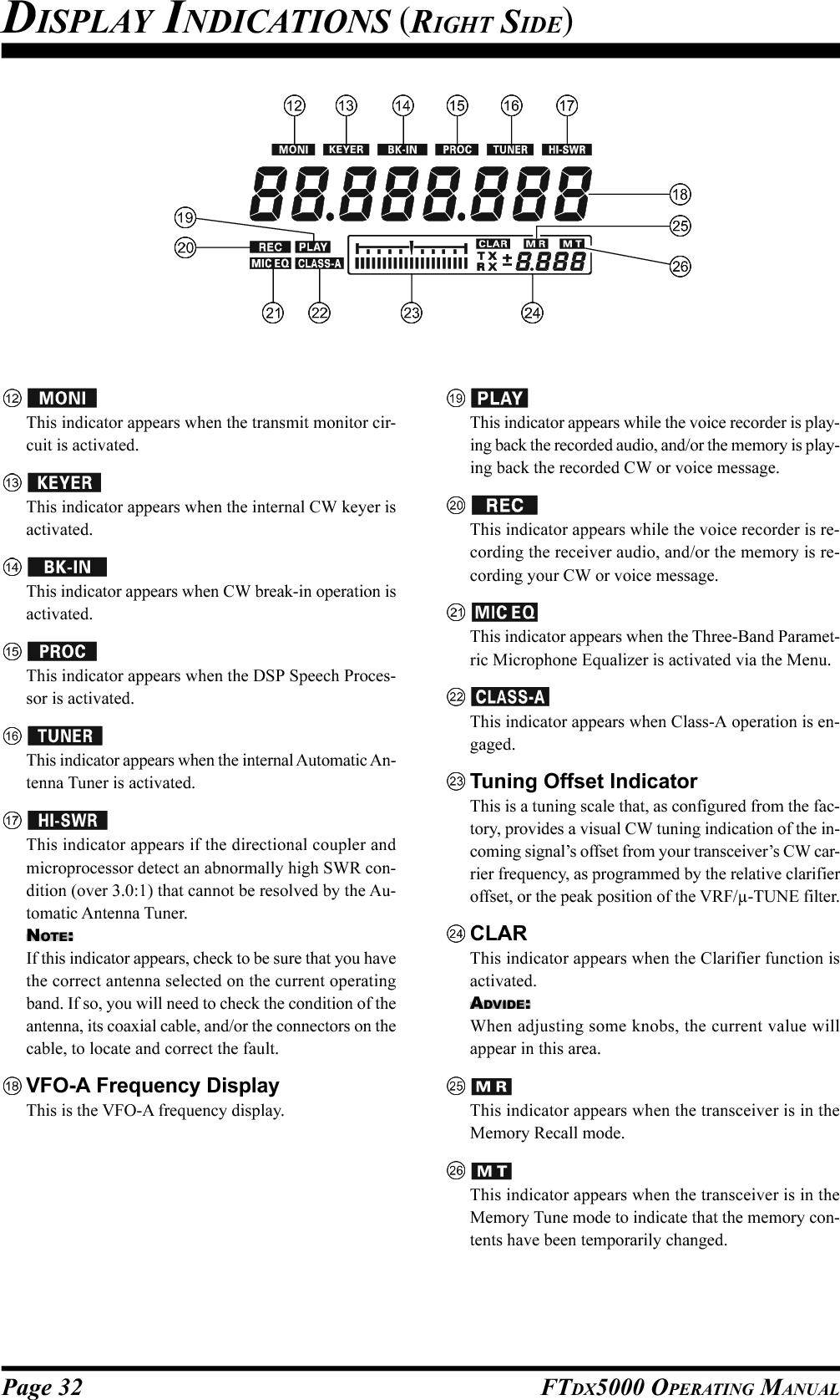
![Page 30 FTDX5000 OPERATING MANUAL(VFO-A) Block Diagram DisplayANT (1, 2, 3, 4, RX):Indicates the antenna selected for operation by the frontpanel [ANT 1-4] and [RX ANT] switches.ATT (OFF, –6 dB, –12 dB, –18 dB):Indicates the attenuation level selected for operationby the front panel [ATT] button.FLT (VRF, µ-TUNE, THRU):Indicates the RF filter selected for operation by thefront panel (VFO-A)[VRF/µ-T] button.ADVICE:The µ-TUNE filter is an option. The “ ” icon willnot appear when the optional µ-TUNE unit is not con-nected.IPO (AMP1, AMP2, IPO1, IPO2):Indicates the front end RF amplifier selected for op-eration by the front panel [IPO] button.R.FLT (300, 600, 3k, 6k, 15k):Indicates the 1st IF Roofing Filter selected for opera-tion with the front panel [R.FLT] button.ADVICE:The 300 Hz Roofing Filter is an option except the MPversion. The “300” icon will not appear when the op-tional 300 Hz Roofing Filter is not installed.AGC (AUTO, FAST, MID, SLOW):Indicates the AGC decay time selected for operationby the front panel [AGC] switch.(VFO-A) Status Indicator:This indicator appears during transmission on the VFO-A frequency.:This indicator appears whenever the VFO-A receiversquelch is open. If this indicator is not showing, andreception seems to have been lost on the VFO-A re-ceiver for no apparent reason, check the position ofthe (VFO-A)[SQL] knob, and rotate it fully counter-clockwise to restore reception.:This indicator appears when the Main Tuning Dial tun-ing rate is selected to fast.:This indicator appears when the Main Tuning Dial knobis locked., , , , , , Displays the currently-selected operating mode forVFO-A.This indicator appears whenever the VFO-A receiver’snarrow IF DSP filter is engaged.The “ ” icon appears when the VFO-A receiver’s(short duration) Noise Blanker is activated.The “ ” icon appears when the VFO-A receiver’s(longer-pulse) Noise Blanker is activated.DISPLAY INDICATIONS (LEFT SIDE)](https://usermanual.wiki/Yaesu-Musen/20361X61.Users-Manual-1/User-Guide-1234776-Page-32.png)
![Page 31FTDX5000 OPERATING MANUAL(VFO-B) Block Diagram DisplayANT (1, 2, 3, 4, RX):Indicates the antenna selected for operation by the frontpanel [ANT 1-4] and [RX ANT] switches.ATT (OFF, –6 dB, –12 dB, –18 dB):Indicates the attenuation level selected for operationby the front panel [ATT] button.FLT (VRF, THRU):Indicates the RF filter selected for operation by thefront panel (VFO-A)[VRF] button.ADVICE:The µ-TUNE filter is an option. The “ ” icon willnot appear when the optional µ-TUNE unit is not con-nected.IPO (AMP1, AMP2, IPO1):Indicates the front end RF amplifier selected for op-eration by the front panel [IPO] button.R.FLT (3k, 6k, 15k):Indicates the 1st IF Roofing Filter selected for opera-tion by the front panel [R.FLT] button.AGC (AUTO, FAST, MID, SLOW):Indicates the AGC decay time selected for operationby the front panel [AGC] switch.This indicator appears whenever the Digital Noise Re-duction feature is activated.(VFO-B) Receiver S-MeterDisplays the strength of signals received on VFO-B.(VFO-B) Status Indicator:This indicator appears during transmission on the VFO-B frequency.:This indicator appears whenever the VFO-B receiversquelch is open. If this indicator is not showing, andreception seems to have been lost on the VFO-B re-ceiver for no apparent reason, check the position ofthe (VFO-B)[SQL] knob and rotate it fully counter-clockwise to restore reception.:This indicator appears when the [CLAR(VFO-B)]knob’s tuning rate is selected to fast.:This indicator appears when the [CLAR(VFO-B)]knob is locked., , , , , , Displays the currently-selected operating mode forVFO-B.This indicator appears whenever the VFO-B receiver’snarrow IF DSP filter is engaged.The “ ” icon appears when the VFO-B receiver’s(short duration) Noise Blanker is activated.The “ ” icon appears when the VFO-B receiver’s(longer-pulse) Noise Blanker is activated.DISPLAY INDICATIONS (LEFT SIDE)](https://usermanual.wiki/Yaesu-Musen/20361X61.Users-Manual-1/User-Guide-1234776-Page-33.png)
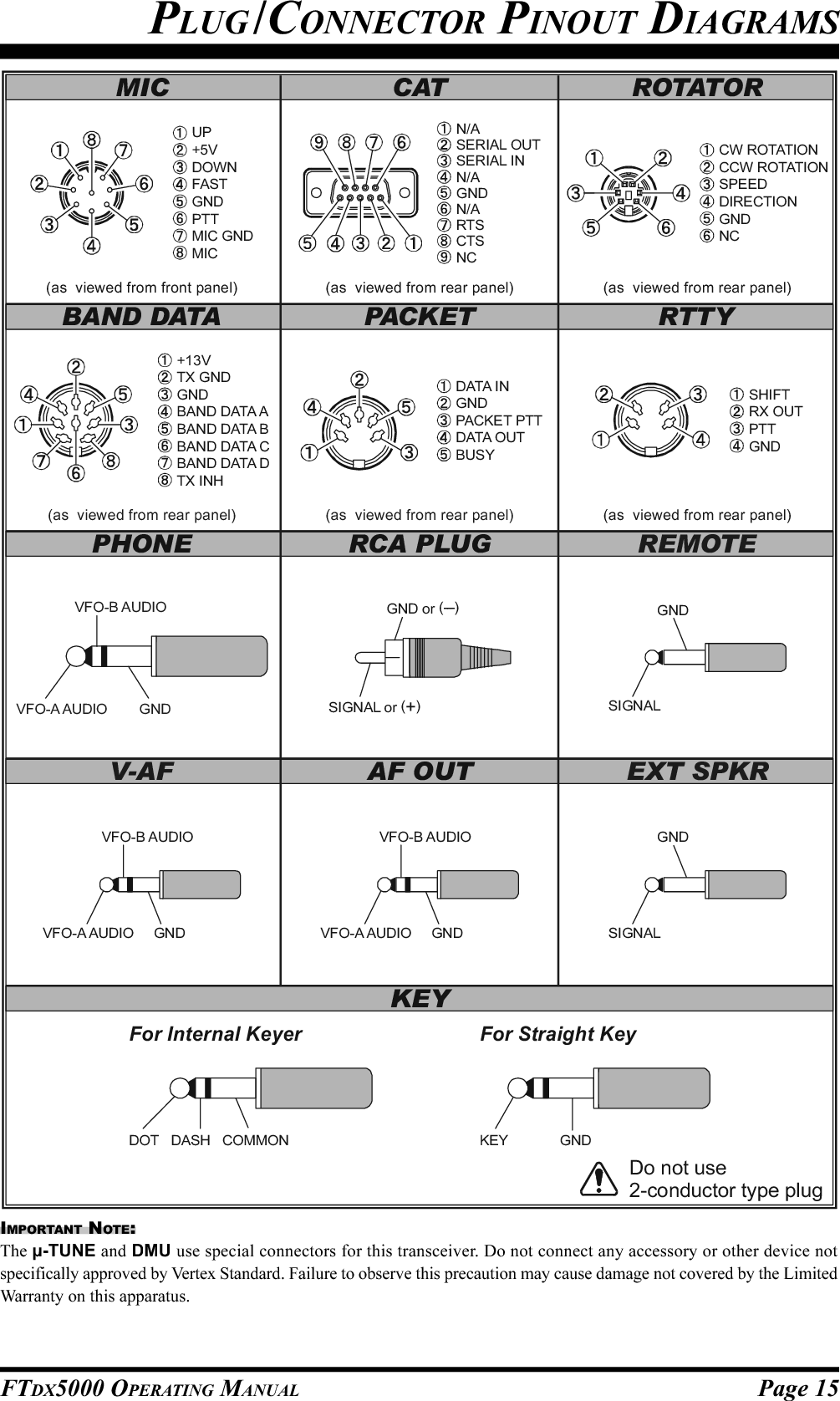
![Page 33FTDX5000 OPERATING MANUALREAR PANEL CONNECTIONSIF OUT JacksThis RCA jack outputs the 9 MHz IF signal of the re-ceived signal when Menu item “109 RGEN IF OUT”is set to “ENABLED”. This signal does not pass throughthe roofing filter.ANT 1, 2, 3, 4 JacksConnect your main antenna(s) here, using a type-M(PL-259) plug and coaxial feedline for each. These an-tenna ports are always used for transmission. They arealso used for reception, unless a separate receive an-tenna is connected to the RX ANT IN jack and usedfor the receiver. The internal antenna tuner affects onlythe antenna(s) connected here, and only during trans-mission.RX ANT IN JackThe BNC jack provides output of the receiver signalfrom the Antenna jacks, which are connected to the“RX” side of the transceiver T/R switching circuitry.The type-M jack is for a separate, receive-only antenna.An antenna connected here can be used when the [RXANT] button on the front panel is pressed.If you want to use some special kind of externalbandpass filter or preamplifier, you may connect itbetween the “RX ANT OUT” and “RX ANT IN” jacks.GNDUse this terminal to connect the transceiver to a goodearth ground, for safety and optimum performance. Usea large diameter, short braided cable for making groundconnections. Please refer to page 9 for other notes aboutproper grounding.µ-TUNE JacksThese jacks are used for signal input/output of the op-tional RF µTuning Kits.ROTATOR JackThis 6-pin MINI-DIN Jack accepts a cable connectedto a YAESU G-800DXA/-1000DXA/-2800DXA An-tenna Rotator (listed models are current as of early2010). You may control the antenna azimuth rotation(and rotation speed) using the Function buttons on thefront panel.BAND DATA JackThis 8-pin output jack provides band selection datawhich may be used for control of optional accessoriessuch as the VL-1000 Solid-state Linear Amplifier.PACKET JackThis 5-pin input/output jack provides receiver audioand squelch signals, and accepts transmit (AFSK) au-dio and PTT control, from an external Packet TNC.Pinout is shown on page 15. The receiver audio levelat this jack is approximately 100 mVp-p (@600 Ohms).RTTY JackThis 4-pin input/output jack provides connections foran RTTY terminal unit. Pinout is shown on page 15.The receiver audio level at this jack is at a constant100-mV (@600 Ohms) level. FSK keying at this jackis accomplished by a closure of the SHIFT line toground by the terminal unit.](https://usermanual.wiki/Yaesu-Musen/20361X61.Users-Manual-1/User-Guide-1234776-Page-35.png)
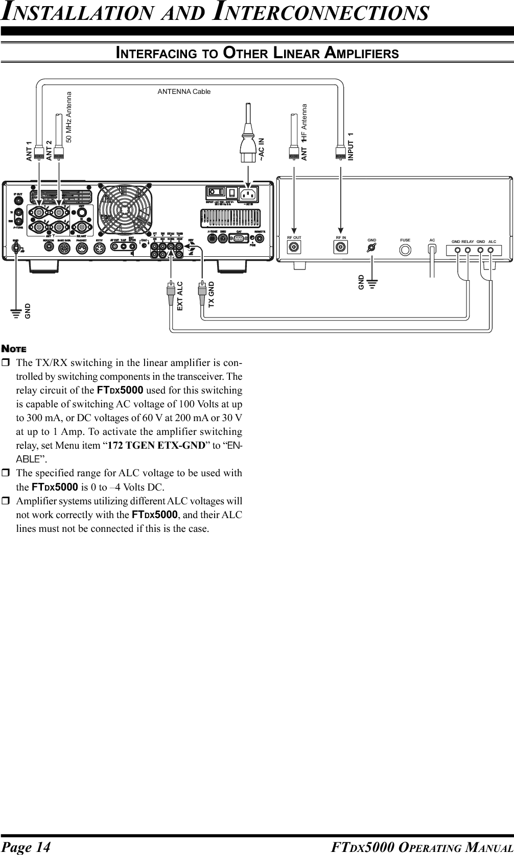
![Page 34 FTDX5000 OPERATING MANUALAF OUT JackThis 3.5-mm, 3-contact jack provides dual-channellow-level receiver output, for recording or external am-plification. Peak signal level is 300 mVp-p at 10 k-Ohms. The VFO-A receiver audio is on the left chan-nel (tip), and the VFO-B receiver audio is on the rightchannel (ring). A stereo amplifier or recorder is rec-ommended, to record each receiver’s audio separatelywhen dual reception is enabled (audio from either re-ceiver, or both, may be used). The front panel [AFGAIN] knobs do not affect the signals at this jack.V-AF JackThis 3.5-mm, 3-contact jack is used for connection tothe optional SM-5000 Station Monitor.EXT SPKR JackThis 3.5-mm, 2-contact jack provides receiving audiooutput from the VFO-A and VFO-B receivers for anexternal loudspeaker or speakers, such as the SP-2000.Inserting a plug into the jack disables the internal loud-speaker. Impedance is 4 ~ 8 Ohms.E.ALC SwitchThis slide switch is used to select the recovery time ofthe ALC. Set this switch to the “1” position when thetransceiver is connected to the optional VL-1000 Solid-state Linear Amplifier.PTTJackThis RCA input jack may be used to provide manualtransmitter activation using a footswitch or otherswitching device. Its function is identical to the [MOX]button on the front panel. The same line is available atthe PACKET and RTTY jacks for TNC control. Opencircuit voltage is +13.5 VDC, and closed-circuit cur-rent is 5 mA.TRV JackThis RCA jack provides a low level RF output for usewith a transverter. Maximum output is approximately–10 dBm (0.1 mW) at 50 Ohms.EXT ALC JackThis RCA input jack accepts negative-going externalALC (Automatic Level Control) voltage from a linearamplifier, to prevent over-excitation by the transceiver.Acceptable input voltage range is 0 to –4 VDC.TX GND JackThis RCA jack is closed to ground while the transmit-ter is engaged. It may be used for control of a periph-eral device, most typically a linear amplifier. To en-able the jack, set Menu item “172 TGEN ETX-GND”to the “ENABLE”.The relay circuit used for this jack is capable of switch-ing an AC voltage of 100 Volts at up to 300 mA, or aDC voltage of 60 V at 200 mA, or DC 30 V at up to 1Amp.REAR PANEL CONNECTIONS](https://usermanual.wiki/Yaesu-Musen/20361X61.Users-Manual-1/User-Guide-1234776-Page-36.png)
![Page 35FTDX5000 OPERATING MANUALREAR PANEL CONNECTIONSMIC (PATCH) JackThis RCA input jack accepts either AFSK or voiceaudio, for transmission. This line is mixed with the mi-crophone audio input line, so the microphone shouldbe disconnected if using this jack and mixing is notdesired. The optimum impedance is 500 ~ 600 Ohms,and the nominal input level should be 5 mV.REC JackThis RCA jack provides low-level receiver audio out-put and transmit (monitor) audio (requires the [MONI]button is turned on), for external recording or externalamplification. Peak signal level is 30 mVp-p at 10 k-Ohms.TX REQ JackWhen this RCA jack is shorted to ground, it puts thetransceiver into the transmit mode, and sends out asteady CW carrier, for linear amplifier or manual an-tenna tuner adjustment.+13.8 V JackThis RCA output jack provides regulated, separatelyfused 13.8 VDC at up to 200 mA, to power an externaldevice such as a packet TNC. Make sure your devicedoes not require more current (if it does, use a separatepower source).KEY JackThis 1/4-inch phone jack accepts a CW key or keyerpaddle. A 2-contact plug cannot be used in this jack.Key-up voltage is +5 V, and key-down current is 1 mA.Plug wiring is shown on page 15, and the jack may beconfigured for keyer, “Bug,” “straight key,” or com-puter keying interface operation via Menu item “059A1A R-TYPE.”Main Power SwitchThis is the main power “on” (I)/“off” (O) switch of thetransceiver. Always turn this switch on before turningon the front panel [POWER] button.If this switch is not turned “on”, the front panel[POWER] switch will not function.Circuit Breaker SwitchThis circuit breaker shuts off in the event of danger-ously high current consumption by the transceiver.ADVICE:If the Circuit Breaker interrupts power, by all meanstry to determine the cause of the over-current condi-tion before re-applying power. To restore the CircuitBreaker after verifying that all is normal, push theswitch in until you hear a “click”.~AC IN JackConnect the supplied 3-wire AC line cord to this socket.AC voltages of 100-240 V may be accommodated bythe transceiver without any sort of modification (uni-versal voltage input).µ-TUNE JackThis 10-pin MINI-DIN jack is used for control of theoptional RF µTuning Kits.DMU JackThis 8-pin MINI-DIN jack accepts a cable connectedto an optional DMU-2000 Data Management Unit orSM-5000 Station Monitor.CAT JackThis 9-pin serial DB-9 jack allows external computercontrol of the transceiver. Connect a serial cable hereand to the RS-232C COM port on your personal com-puter (no external interface is required).PGM (PROGRAM) SwitchThis slide switch is used for updating the transceiver’sfirmware. The update software and instructions areavailable for download from the Vertex Standardwebsite (http://www.yaesu.com/).REMOTE JackBy plugging the supplied FH-2 Remote Control Key-pad into this jack, direct access to the CPU is provided,for control of functions such as the audio playback fea-ture, and the contest memory keyer, plus frequency andfunction control.](https://usermanual.wiki/Yaesu-Musen/20361X61.Users-Manual-1/User-Guide-1234776-Page-37.png)
![Page 36 FTDX5000 OPERATING MANUALFH-2 SWITCHESThe supplied Remote Control Keypad “FH-2” can be used to control the voice memory capability for the SSB/AM/FMmodes, and the contest memory keyer for the CW mode. You can also play-back up to 15 seconds of incoming receivedaudio, for verification of a missed callsign or other purposes. Some specific capabilities of the FH-2 are:On SSB/AM/FM modes, five channels of storage and playback of voice memory (20 seconds each), using your ownvoice for recording (see page 80).On CW mode, the FH-2 provides storage and recall of CW messages for repetitive CQ and contest number transmis-sions (see pages 94 and 96).Play-back of the last 15 seconds of incoming receiver audio (see page 45).[1], [2], [3], [4], [5] SwitchesThese buttons work as the Voice Memory and CW Mes-sage Memory Selection Key.In the case of Voice Memory, up to 20 seconds of au-dio may be stored on each channel.For CW Messages and CW Text Messages, up to 50characters (“PARIS” specification) may be stored intoeach channel.[], [], [], [] SwitchesThese buttons are used for navigation when selectingtext characters for the programming of Contest and Textmemories.[P/B] SwitchThis button is used for playing back the last 15 sec-onds of recorded receiver audio.LOCKOFFON[LOCK] SwitchThis button may be used to lock out the FH-2 key but-tons, to prevent accidental activation of FH-2 opera-tions.[MEM] SwitchPress this button to store either a Voice Memory, or aContest Keyer Memory.[DEC] SwitchWhen utilizing the sequential contest number capabil-ity of the Contest Keyer, press this button to decre-ment (decrease) the current Contest Number by onedigit (i.e. to back up from #198 to #197, etc.).](https://usermanual.wiki/Yaesu-Musen/20361X61.Users-Manual-1/User-Guide-1234776-Page-38.png)
![Page 37FTDX5000 OPERATING MANUALBefore turning on main power, please verify the following precautions once more.Verify all ground connections are secure. See page 9 for details.Connect the antenna(s) to the rear-panel Antenna jack(s). See page 10 for details.Connect the microphone (and/or key or paddle). See pages 11 and 12 for details.If using a linear amplifier, verify the interconnections have been successfully completed? See pages 13 and 14 fordetails.Rotate both [AF GAIN] controls to their fully counter-clockwise positions, to avoid a loud blast of audio when thetransceiver turns on. See page 21 for details.Rotate the [RF PWR] control fully counter-clockwise, to set minimum power to begin. See page 20 for details.If your AC mains power should suffer a significant fluctuation or interruption, we recommend that you go through acomplete power-up cycle, in order to ensure that all circuits are properly initialized. To do this, be sure the front panel[POWER] switch is turned off, then set the rear panel main power switch to the “O” position. Now unplug the ACcable from the rear panel, and wait ten seconds before continuing with the start-up procedure described on the nextpage.BASIC OPERATION:RECEIVING ON AMATEUR BANDS](https://usermanual.wiki/Yaesu-Musen/20361X61.Users-Manual-1/User-Guide-1234776-Page-39.png)
![Page 38 FTDX5000 OPERATING MANUALMain Tuning Dial knob[ANTENNA] Buttons [BAND] Buttons(VFO-B)[SQL] Knob[BAND/MHz] Button[FAST] Button[CLAR(VFO-B)] Knob1. Plug the AC cable back in, set the rearpanel main power switch to the “I”position.2. Press and hold in the front panel[POWER] switch for one second to turnthe transceiver on.3. The transceiver will start up on 7.000.00MHz LSB, and normal operation may begin.NOTE:To turn power off, press and hold in the front panel[POWER] switch for one second.4. Rotate the (VFO-A)[AF GAIN]knob to set a comfortable audio levelon incoming signals or noise. Clock-wise rotation of the (VFO-A)[AFGAIN] knob increases the volumelevel.NOTE:When using headphones, start by rotating the (VFO-A)[AF GAIN] knob counter-clockwise, then bring thevolume level up after you put the headphones on. Thiswill minimize the chance of damage to your hearingcaused by an unexpectedly-high audio level.5. Press the (VFO-A)[RX]button to engage the VFO-A receiver; the imbeddedLED will glow green.ADVICE:If you press the (VFO-A)[RX] button when the LED is already glowinggreen, the LED will begin blinking; this indicatesthat the VFO-A receiver is temporarily muted. Pressthe (VFO-A) [RX] button once more to restoreVFO-A receiver operation.Press the (VFO-B)[RX] button toengage Dual Reception (using theVFO-B receiver in addition to theVFO-A receiver). When you pressthe (VFO-B)[RX] button, it willglow green; pressing the buttononce more will turn the VFO-Breceiver off, and the LED will godark. Use the (VFO-B)[AFGAIN] knob to adjust the VFO-B receiver volume level.6. Press the [BAND] buttoncorresponding to the Ama-teur band you wish to oper-ate on.ADVICE:One-touch selection ofeach Amateur band be-tween 1.8 and 50 MHz is provided.The FTDX5000 utilizes a triple band-stack VFOselection technique. This permits you to store up tothree favorite frequencies and modes for each bandin the VFO registers. For example, you may storeone frequency for 14 MHz CW, one for RTTY, andone for USB, then recall each VFO by successive,momentary presses of the [14] MHz band button.Each Amateur band button has three frequency/mode settings associated with it.[POWER] Switch(VFO-A)[RX] ButtonBASIC OPERATION:RECEIVING ON AMATEUR BANDSHere is the typical start-up procedure for normal operation:(VFO-A)[SQL] Knob [MODE] Buttons(VFO-B)[AF GAIN] Knob(VFO-A)[AF GAIN] Knob[()DOWN] /[()UP] Buttons(VFO-B)[RX] Button](https://usermanual.wiki/Yaesu-Musen/20361X61.Users-Manual-1/User-Guide-1234776-Page-40.png)
![Page 39FTDX5000 OPERATING MANUALIf you press the[BAND/MCH] but-ton briefly, the buttonglows red, and the[CLAR(VFO-B)]knob may be used asthe band selectionknob.7. Press the [(DOWN)]/[(UP)] buttons to tune theVFO-A frequency in 1 MHzsteps.ADVICE:You may change the tuning step to 100 kHz via Menuitem “144 TUN MHz SEL”. See page 133.8. Move the [ANT 1-4] button up or down to select theappropriate antenna for the band in use. Alternatively,you may also press the [RX ANT] button to select thereceive antenna, if one is con-nected. Up to four TX/RX anten-nas and one RX-only antenna maybe connected.ADVICE:Your antenna selection is “remembered” (in con-junction with the frequency and mode) in the VFOregister in use, when you choose that particularantenna.When VFO-A and VFO-B are switched to the sameantenna jack, VFO-B receiver will be automaticallyconnected to the RX ANT jack.When both VFO-A and VFO-B are switched to theRX ANT, the signal output from the RX OUT jackis connected to the VFO-A receiver.9. Press the appropriate [MODE]button to select the desired op-erating mode.ADVICE:By convention in the Ama-teur bands, LSB is used onthe 7 MHz and lower bands(with the exception of 60 meters), while USB isutilized on the 14 MHz and higher bands.When changing modes from SSB to CW, you willobserve a frequency shift on the display. This shiftrepresents the BFO offset between the “zero beat”frequency and the audible CW pitch (tone) you canhear (the pitch is programmed by the [PITCH]knob), even though the actual tone that you hear isnot changing. If you do not want this frequency shiftto appear when changing modes, you may changethe BFO offset setting in Menu item “066 A1A FRQDISP”, described on page 127.When operating on the FM modein the VFO-A, rotate the (VFO-A)[SQL] (Squelch) knob clock-wise just to the point where thebackground noise is silenced. Thisis the point of maximum sensitivity to weak sig-nals. Excessive advancement of theSquelch knob will degrade the abil-ity of the receiver to detect weaksignals. Adjustment of the VFO-BSquelch is accomplished using the(VFO-B)[SQL] knob.10.Rotate the Main Tuning Dial knob to tune around theband, and begin normal operation.ADVICE:Clockwise rotation of the Main Tuning Dial knobincreases the operating frequency, one “step” of thesynthesizer at a time; similarly, counter-clockwiserotation of the Main Tuning Dial knob will decreasethe frequency.A “normal” and a “fast”step choice is available oneach operating mode.Pressing the [FAST] but-ton engages the “Fast”tuning selection.BASIC OPERATION:RECEIVING ON AMATEUR BANDSOPERATING MODE 1 STEP 1 DIAL ROTATIONLSB, USB, CW, 10Hz 10kHzRTTY, PKT(LSB)[100Hz][100kHz]AM, FM, PKT(FM)100Hz [1kHz]100kHz [1MHz][ ] : [FAST] switch set to “ON”It is possible to set the frequency dial rotation stepsseparately, solely for CW mode operation, usingMenu items “142 TUN DIAL STP”, and “143 TUNCW FINE”. See page 133.If you want to navigate frequency change quickly,there are several techniques available:Direct keyboard entry of the frequency (see page49).Use of the microphone [UP]/[DWN] scanningkeys, if your microphone is so equipped (seepage 49).ANTENNA SWITCH(VFO-A)ANTENNA SWITCH(VFO-B)RX ANTENNA SWITCH(VFO-B)RX ANTENNA SWITCH(VFO-A)TX/RX RELAY Transmitter SectionVFO-A ReceiverVFO-B ReceiverBPFANT “1”ANT “3”ANT “2”ANT “4”RX ANTRX OUTDividerSEPARATESEPARATEANTENNA CIRCUIT DIAGRAM](https://usermanual.wiki/Yaesu-Musen/20361X61.Users-Manual-1/User-Guide-1234776-Page-41.png)
![Page 40 FTDX5000 OPERATING MANUALBASIC OPERATION:RECEIVING ON AMATEUR BANDSCLAR (CLARIFIER) OPERATION ON VFO-AThe [RX CLAR/FAST], [CLEAR], [TX CLAR/LOCK] buttons, and the [CLAR(VFO-B)] knob are used to offset thereceive, the transmit, or both frequencies from their settings on VFO-A (the Clarifier does not affect VFO-B). The foursmall numbers on the LCD display show the current Clarifier offset. The Clarifier controls on the FTDX5000 are designedto allow you to preset an offset up to ±9.999 kHz without actually retuning, and then activate it usning the Clarifier [RXCLAR/FAST] and [TX CLAR/LOCK] buttons. This feature is ideal for following a drifting station, or for setting the smallfrequency offsets sometimes utilized in DX “Split” operation.Here is the technique for utilizing the Clarifier:1. Press the [RX CLAR/FAST] button. The “ ” and“” icons will appear in the display, and the pro-grammed offset will be applied tothe receive frequency.ADVICE:If the “ ” and “ ” icons do not appear, checkto see if the [A/B] button glows orange. If so, press the[A/B] button to cause the LED in the [A/B] button togo out. Now, press the [RX CLAR/FAST] button tobegin clarifier operation.2. Rotation of the [CLAR(VFO-B)] knob will allow youto modify the initial offset on thefly. Offsets of up to ±9.999 kHzmay be set using the Clarifier.To cancel Clarifier operation, press the [RX CLAR/FAST]button. The “ ” and “ ” icons will disappear fromthe display.ADVICE:Turning the clarifier “off” simply cancels the applicationof the programmed offset from the receive and/or transmitfrequencies. To clear out the programmed clarifier offsetaltogether, and reset it to “zero,” press the [CLEAR] but-ton.TX CLARWithout changing the receive frequency, you mayalternatively apply the Clarifier offset to the trans-mit frequency (typically, for “split” DX pile-ups).See page 82 for details.The Tuning Offset Indicator provides a graphical representation of the Clarifier offset.In CW mode, the Tuning Offset Indicator is depicts the CW Center Tuning, instead of the Clarifier Offset, this is thefactory default setting. If you wish to change this, so that the Clarifier Offset is also displayed on CW, use thefollowing procedure:1. Press the [MENU] button to enter the Menu mode.2. Rotate the (VFO-A)[SELECT] knob to selectMenu item “012 DISP BAR SEL”.3. Rotate the (VFO-B)[SELECT] knob to select“CLAR (Clarifier)” (replacing the default “CWTUNE (CW TUNING)”selection).4. Press and hold in the[MENU] button for twoseconds to save the newsetting and exit to nor-mal operation.[CLAR(VFO-B)] Knob[RX CLAR/FAST] Button[CLEAR] Button[A/B] Button[Plus (+) Offset][Zero Offset](Minus (–) Offset)(VFO-B)[SELECT] Knob[MENU] Button(VFO-A)[SELECT] Knob](https://usermanual.wiki/Yaesu-Musen/20361X61.Users-Manual-1/User-Guide-1234776-Page-42.png)
![Page 41FTDX5000 OPERATING MANUALLOCKYou may lock the setting of the Main Tuning Dial knob, to prevent accidental frequency change.To lock out the Main Tuning Dial knob, just press the[LOCK] button that is located to the right of the MainTuning Dial knob. To unlock the Dial setting, and restorenormal tuning, just press the [LOCK] button once more.When the Main Tuning Dial knob is “locked”, the blue“” icon will appear on the display.DIMThe illumination level of the analog meter and frequency display may be reduced, if you are using the transceiver in a darkenvironment where high brightness is not desired.To reduce the illumination level, press the [DIM] button,located to the left of the analog meter. To restore full bright-ness, press the [DIM] button once more.ADVICE:The amount of brightness may be customized for differentfront panel areas. The follwing menu settings are effectivewhen the [DIM] button is depresses:008 DISP DIM MTR: for analog meter009 DISP DIM VFD: for frequency dispaly010 DISP DIM OLE:SUB DISPLAY windows011 DISP DIM ELCD: for Spectrum Scope displayof the optional SM-5000 Sta-tion Monitor[LOCK] Button[LOCK] ButtonOPERATION ON 60-METER (5 MHZ) BAND (U.S. VERSION ONLY)The recently-released 60-meter band is covered, in the FTDX5000, by five special, fixed memory channels. These channels areset to USB, and they appear between the “last” PMS channel (“P-9U”) and the first “regular” memory channel (Channel 1).To operate on the 60-meter (5 MHz) band:1. Press the [V/M] button once, if neccessary, to enter the“Memory” mode (the “ ” icon will appear on thedisplay.2. Press and hold in the [BAND/MCH] button for twoseconds. The button will glow yellow to signify thatrotation of the [CLAR(VFO-B)] knob will allow se-lection of the memory channel.3. Memory channels “US-1” through “US-5” are pre-pro-grammed, at the factory, with the permitted frequen-cies in the 5 MHz band, and the USB mode is auto-matically selected on these channels.4. To exit from 60-meter operation and return to the VFOmode, just press the [V/M] button.NOTE:The frequencies and operating mode for 5 MHz band op-eration are both fixed, and may not be changed.[CLAR(VFO-B)] Knob[V/M] Button[BAND/MCH] ButtonCHANNEL NUMBERUS-1US-2US-3US-4US-5FREQUENCY5.3320 MHz5,3480 MHz5.3680 MHz5.3730 MHz5.4050 MHzBASIC OPERATION:RECEIVING ON AMATEUR BANDS](https://usermanual.wiki/Yaesu-Musen/20361X61.Users-Manual-1/User-Guide-1234776-Page-43.png)
![Page 42 FTDX5000 OPERATING MANUALQUICK POINT:By convention in the amateur bands, LSB is used on the 7MHz and lower bands (with the exception of 60 meters),while USB is utilized on the 14 MHz and higher bands.ADVICE:When operating in Dual Receive, the manner in whichthe audio is fed to the left and right headphones (Ste-reo, Monaural, or Mixed) may be configured usingMenu item “108 ROUT HEADPHN” (see page 130).When changing modes from SSB to CW, you will ob-serve a frequency shift on the display. This shift repre-sents the BFO offset between the “zero beat” frequencyand the audible CW pitch (tone) you can hear (the pitchis programmed by the [PITCH] knob), even thoughthe actual tone that you hear is not changing. If you donot want this frequency shift to appear when changingmodes, you may change the BFO offset setting in Menuitem “066 A1A FRQ DISP”, described on page 127.When operating on the FM mode on the VFO-B re-ceiver, rotate the (VFO-B)[SQL] knob clockwise justto the point where the background noise is silenced.This is the point of maximum sensitivity to weak sig-nals. Excessive advancement of the (VFO-B)[SQL]knob will degrade the ability of the receiver to detectweak signals. Adjustment of the VFO-A squelch is ac-complished using the (VFO-A)[SQL] knob.DUAL RECEIVEThe FTDX5000 is capable of simultaneous reception on the same amateur band, using the VFO-A and VFO-B receivers,in the “Dual Receive” mode. This is especially useful for DX work, here is the operating procedure for Dual Receiveoperation.CONVENIENCE FEATURES1. While receiving on VFO-A, engage the VFO-B receiverby pressing the (VFO-B)[RX] button, located to theupper left of the [CLAR(VFO-B)] knob. You will nowbe receiving on the two frequencies shown on the LCDdisplay (for VFO-A) and SUB DISPLAY-I (for VFO-B).2. Adjusting the volume:To adjust the VFO-A audio level, rotate the (VFO-A)[AF GAIN] knob. To adjust the VFO-B audio level,rotate the (VFO-B)[AF GAIN] knob. In both cases,clockwise rotation of the knob will increase the vol-ume level.3. Press the [B] button, located to the upper left of theMain Tuning Dial knob. The [B] button will glow or-ange, and you may now change the operating mode ofthe VFO-B receiver by pressing the appropriate[MODE] selection button.4. You may also press the [BAND] buttons to select theoperating band for the VFO-B receiver.5. To return the mode and band selections to VFO-A, pressthe [A] button, located to the left of the [B] button.The [A] button will glow red, and you may now changethe operating mode and band of the VFO-A receiver.6. Rotate the Main Tuning Dial knob to adjust the MainVFO-A frequency, and rotate the [CLAR(VFO-B)]knob to adjust the VFO-B frequency.ADVICE:If the VFO-B frequency does not change, check to seeif the orange LED in the [A/B] button is illuminated. Ifnot, pressing the [A/B] button will cause the [A/B] but-ton to glow orange. Now, rotate the [CLAR(VFO-B)]knob to adjust the VFO-B frequency.7. To cancel Dual Receive operation, and receive onlyon the VFO-A receiver, press the (VFO-B)[RX] but-ton; the imbedded green LED will go out, andmonoband operation on the VFO-A receiver will re-sume.NOTE:Remember that, while the [B] button glows orange, anymode or band changes will still be applied to the VFO-Breceiver, whether or not Dual Receive is engaged.[CLAR(VFO-B)] Knob[A/B] Button[BAND] Buttons[MODE] ButtonsSUB DISPLAY-I(VFO-B)[RX] Button[A] / [B] Buttons(VFO-A)[SQL] Knob(VFO-B)[SQL] Knob(VFO-A)[AF GAIN] Knob(VFO-B)[AF GAIN] Knob](https://usermanual.wiki/Yaesu-Musen/20361X61.Users-Manual-1/User-Guide-1234776-Page-44.png)
![Page 43FTDX5000 OPERATING MANUALCONVENIENCE FEATURESDUAL RECEIVEUsing Headphones for Dual ReceiveTo take advantage of dual reception, you will want to con-nect stereo headphones to the PHONES jack. In additionto the AF GAIN controls, headphone audio mixing canalso be configured as desired from Menu item “108 ROUTHEADPHN”. Three audio mixing schemes are selectableas follows:SEPARETE: Audio from the VFO-A receiver is heard onlyin the left ear, and VFO-B receiver audiosolely in the right ear.CONBINE1: Audio from both VFO-A and VFO-B receiv-ers can be heard in both ears, but VFO-Baudio is attenuated in the left ear and VFO-A audio is attenuated in the right ear.CONBINE2: Audio from both VFO-A and VFO-B receiv-ers are combined and heard equally in bothears (“Monaural” mode).VFO Tracking FeatureYou may lock VFO-B to track in unison with VFO-A whenthe main tuning dial is adjusted. See page 83 for details.Go to Menu item “038 GENE TRACK” to set the track-ing function as follows:OFF: VFO-A and VFO-B tune independently (Default)BAND: Band Change operations will be applied to VFO-A and VFO-B simultaneously.FREQ: VFO-A and VFO-B tune in unison when The MainTuning dial is adjusted. However, VFO-B maybe adjusted separately.Sideband Diversity ReceptionHere you receive a single AM signal through the two re-ceivers, each receiving the opposite sideband. Skywave-propagated signals often show phase distortion in thismode, but it gives you a view of the entire passband, fromwhich you can then select the best sideband for listening(or for SWL Dx’ing, you may want to listen to both side-bands at the same time, to get the best copy). Ongroundwave signals, where the phase of the sidebands islikely to be the same, there is an interesting sense of depthto the signal.To tune in a signal using this mode, you should have ste-reo headphones connected to the front panel PHONESjack.Set VFO-A to either LSB or USB mode, and tune forzero beat on the desired signal.Press the [AB] button to copy this mode and fre-quency into VFO-B, then press the [MODE] button toselect the opposite sideband for VFO-A.If using headphones, set the headphone mixing schemeto the “CONBINE1” mode via Menu item “108 ROUTHEADPHN”, and activate dual reception.Adjust the [AF GAIN] knob(s) to balance the volumeof the two receivers.If interference is present on one of the channels, youmay have to turn its [AF GAIN] knob to suppress thatchannel (or press the green [RX] button to disable thereceiver with the sideband experiencing interference).Otherwise, try changing the headphone audio mixingscheme to “CONBINE2” or “SEPARETE” in the Menuitem “108 ROUT HEADPHN”, for different effects(or try settings with similar effects, if you use an exter-nal audio amplifier). Although you don’t get the “ste-reophonic” effect in the monaural mode, the two sig-nals are still mixed, offering the potential for muchbetter copy than in regular AM or even single-side-band ECSS modes.](https://usermanual.wiki/Yaesu-Musen/20361X61.Users-Manual-1/User-Guide-1234776-Page-45.png)
![Page 44 FTDX5000 OPERATING MANUALBandwidth Diversity ReceptionThis mode involves receiving the same signal through twodifferent bandpass filters. The frequency and mode of bothVFO-A and VFO-B are the same. VFO-A can be set up fora wide bandpass, using the [WIDTH] knobs, and VFO-Bfor a narrow bandpass, resulting in a spatial perception ofthe channel. Although any mode (except FM) can be used,CW offers the widest array of choices, and perhaps themost startling effects on crowded channels.Stereo headphones or external stereo speakers are recom-mended for this mode. To set up the transceiver for band-width diversity reception:Select the desired mode on VFO-A.Tune to the signal of interest.Press the [AB] button to copy this mode and fre-quency into the VFO-B.If using headphones, set the headphone mixing schemeto the “CONBINE1” mode via Menu item “108 ROUTHEADPHN”, and activate dual reception.Adjust the [AF GAIN] knob(s) to balance the volumeof the two receivers.Now try manipulating the [SHIFT] and [WIDTH]knobs to observe the interesting effects of bandwidthdiversity.CONVENIENCE FEATURESDUAL RECEIVEPolarity DiversitySimilar in concept to the bandwidth diversity justdescribed, another interesting capability of theFTDX5000 dual reception, is the ability to use twodifferent antennas on the same frequency. For ex-ample, you might have a horizontal Yagi on the mainband, and a vertical antenna on the sub band, thenlock the two frequencies together and engage dualreception.Frequently, the fading observed on the HF bands isnot so much a change in ionization level, but rathera shift in the polarization of the signal as it travelsto and from the ionosphere. Having an opposite-polarization antenna available can fill in the signalduring deep fades. You may then transmit on which-ever antenna is providing the strongest signal at themoment (see the discussion below on Split Fre-quency operation).](https://usermanual.wiki/Yaesu-Musen/20361X61.Users-Manual-1/User-Guide-1234776-Page-46.png)
![Page 45FTDX5000 OPERATING MANUALCONVENIENCE FEATURESP.BACK (AUDIO PLAYBACK) FROM MAIN (VFO-A) RECEIVERWhen Audio Playback is engaged by the operator, the FTDX5000 begins automatically recording the last 15 seconds ofincoming receiver audio on VFO-A. Recording is controlled with the supplied FH-2 Remote Control Keypad, plugged intothe rear panel REMOTE jack. This capability is especially useful for confirming a callsign that may have been difficult tocopy due to noise or QRM, etc.RecordingPress and hold in the FH-2’s [P/B] key for two sec-onds to initiate recording. The “ ” icon will ap-pear in the display to confirm that recording is inprogress.Press the FH-2’s [P/B] key briefly to halt recording;the “ ” icon will go out.LOCKOFFONPlaybackPress the FH-2’s [P/B] key briefly, after recording hasbeen halted, to begin playback of the recorded audio;the “ ” icon will appear in the display to confirmthat playback is in progress. The last 15 seconds ofaudio will be heard in the speaker or headphones. Ifyou do not intervene, the entire 15 seconds will beplayed back, repeating endlessly.To halt playback at any time, just press the [P/B] keybriefly again. The next time you press the [P/B] key, itwill pick up the playback where you left off.ADVICEYou may adjust the playback level of the recording withthe main [AF GAIN] knob.StartStop15 Seconds](https://usermanual.wiki/Yaesu-Musen/20361X61.Users-Manual-1/User-Guide-1234776-Page-47.png)
![Page 46 FTDX5000 OPERATING MANUAL“MY BANDS” OPERATIONWhen operating on an amateur band, it is possible to use the [CLAR(VFO-B)] knob to change the selected operating band.The “My Bands” feature allows you to designate several amateur bands, and make only those bands available for selectionwith the [CLAR(VFO-B)] knob.This feature can be very useful in a contest, where the 10/18/24 MHz bands are not used, or if you do not have antennas forsome bands.“My Bands” Setup1. Press the [MENU] button to engage the Menu mode.2. Rotate the (VFO-A)[SELECT] knob to select Menuitem “150 TUN MY BAND”.3. Rotate the (VFO-B)[SELECT] knob to choose a bandthat you wish to skip (omit) from the band-selectionloop (when using the [CLAR(VFO-B)] knob for bandselection). The available choices are 1.8M/3.5M/7M/10M/14M/18M/21M/24M/28M/50M/GEN(GeneralBand)/T14M(Transverter “1”)/T28M(Transverter“2”)/T50M(Transverter “3”).4. Press the [ENT] button (one of the [BAND] buttons)to set the selected band to “skipped”. The “ON” nota-tion at the right of the band notation will change to“OFF”.5. Repeat steps 3 and 4 to select (“ON”) or deselect(“OFF”) as many bands as you like.6. Press and hold in the [MENU] button for two secondsto lock in the new configuration and exit to normaloperation.ADVICE:The “My Band” feature affects only VFO-A band.CONVENIENCE FEATURES“My Band” Operation1. Press the [V/M] button once, if neccessary, to enter the“VFO” mode.2. Press the [BAND/MCH] button briefly; the button willglow Red.3. Rotate the [CLAR(VFO-B)] knob to choose the ama-teur band on which you wish to operate. Only thoseamateur bands that have not been skipped will appearas you scroll through the bands.(VFO-B)[SELECT] Knob[MENU] Button(VFO-A)[SELECT] Knob[CLAR(VFO-B)] Knob[V/M] Button[BAND/MCH] Button14 MHz14 MHz18 MHz50 MHz21 MHz21 MHz7 MHz7 MHz5 MHz1.8 MHz28 MHz28 MHz24 MHz3.5 MHz3.5 MHz10 MHz14 MHz21 MHz7 MHz28 MHz3.5 MHz](https://usermanual.wiki/Yaesu-Musen/20361X61.Users-Manual-1/User-Guide-1234776-Page-48.png)
![Page 47FTDX5000 OPERATING MANUALCONVENIENCE FEATURESBAND STACK OPERATIONThe FTDX5000 utilizes a triple band-stack VFO selection technique that permits you to store up to three favorite frequen-cies and modes onto each band’s VFO register. For example, you may store one frequency each on 14 MHz CW, RTTY, andUSB, then recall each VFO by successive, momentary presses of the [14] MHz band button. Each Amateur band key maysimilarly have up to three frequency/mode settings applied. Both the VFO-A and VFO-B systems have their own, indepen-dent, band stacks.A typical setup, for the 14 MHz band, might be arrangedlike this:1. Program 14.025 MHz, CW Mode, then press the [14]MHz band button;2. Program 14.080 MHz, RTTY Mode, then press the [14]MHz band button;3. Program 14.195 MHz, SSB Mode, then press the [14]MHz band button.With this configuration, successive momentary presses ofthe [14] MHz band button will allow you to toggle se-quentially through these three VFO configurations.C.S (CUSTOM SWITCH)An often-used Menu mode selection may be programmed to the front panel [C.S] button.C.S Setup1. Press the [MENU] button to engage the Menu mode;the Menu list will appear on the SUB DISPLAY win-dows.2. Rotate the (VFO-A)[SELECT] knob to select theMenu item you want to be able to access via the [C.S]button.3. Press and hold in the [C.S] button for two seconds tolock in your selection.4. Press and hold in the [MENU] button for two secondsto save the new configuration and exit to normal op-eration.Menu Selection Recall via [C.S] button1. Press the [C.S] button. The programmed Menu itemwill appear on the display.2. You may now rotate the (VFO-B)[SELECT] knob tochange the setting of this menu item.3. Press the [MENU] button for two seconds, when youare done, to save the new configuration and exit tonormal operation.USBRTTYCW(VFO-A)[SELECT] Knob[MENU] Button[C.S] Button(VFO-B)[SELECT] Knob[MENU] Button[C.S] Button[BAND] Button](https://usermanual.wiki/Yaesu-Musen/20361X61.Users-Manual-1/User-Guide-1234776-Page-49.png)
![Page 48 FTDX5000 OPERATING MANUALROTATOR CONTROL FUNCTIONSWhen using a YAESU model G-800DXA, G-1000DXA, or G-2800DXA rotator (not supplied), it is possible to control itfrom the front panel of the FTDX5000.1 Press and hold in the [ENT] button (one of the [BAND]buttons) for two seconds. The SUB DISPLAY win-dows will change, and display the “Rotator Control”configuration.2 Press either the [3.5(2)] button or the [7.0(3)] buttonto rotate the antenna. Pressing the [3.5(2)] button willcause rotation to the left (counter-clockwise), whilepressing the [7.0(3)] button will cause rotation to theright (clockwise).3 Press the [14(5)] button or the [18(6)] button to con-trol the speed of rotation. Pressing the [14(5)] buttonwill cause slower rotation, while pressing the [18(6)]button will speed up rotation. Usually, you will be us-ing the “100%” setting.When you are through exercising rotator control, press the[ENT] button briefly. The SUB DISPLAY windows willreturn to the normal display.CONVENIENCE FEATURESIMPORTANT NOTESet the FTDX5000 to match the starting pointof your rotator control indicator needle viaMenu item “014 DISP RTR STU”. The defaultsetting is “0°” (north). If your controller start-ing point is south, the Menu item “014 DISPRTR STU” must be set to “180°”. If not setproperly the FTDX5000 display will not showthe correct direction.When the rotator control indicator needle doesnot indicate the precise antenna direction, ad-just the indicator needle precisely to the antennadirection via Menu item “015 DISP RTR ADJ”.[ENT] Button[3.5(2)], [7(3)] Button[14(5)], [18(6)] ButtonANT 1~AC INANT 2EXT CONTROLREMOTECONTROLROTEXTCONT ROLSELECTSWITCHPRESETADJOPERATIONMODEADJ. MODE F ULLSCALEADJOVERLAPLED ADJOUT VOLADJABOPTIONAL CONNECTION CABLE ()T9101556Counter-clockwise Rotation Clockwise RotationSpeed Down Speed Up](https://usermanual.wiki/Yaesu-Musen/20361X61.Users-Manual-1/User-Guide-1234776-Page-50.png)
![Page 49FTDX5000 OPERATING MANUALMORE FREQUENCY NAVIGATION TECHNIQUESKeyboard Frequency EntryYou may enter operating frequencies, for either the VFO-A or VFO-B bands, using the front panel band/frequencyselection keys.Example 1: Enter 14.250.000 MHz into VFO-A1. Press the [ENT] button to engage the direct frequencyentry process. Now, be-ginning with the “10MHz” digit of the fre-quency (the leftmostdigit), we will enter therequired digits of the fre-quency.2. Press, in order, the digits of the operating frequency,using the [BAND] buttons (which have the frequency-entry digit or decimal point on the right side of theslash bar). In this example, enter[1.8/1] [10/4] [GEN/.] [3.5/2] [14/5] [50/0] [50/0] [50/0] [50/0]The decimal point after the “MHz” portion of the fre-quency must be entered, but no decimal point is re-quired after the “kHz” portion.3. Press the [ENT] button once more. A short “beep” willconfirm that the frequency entry was successful, andthe new operating frequency will appear on the Main(VFO-A) frequency display fields.Example 2: Enter 7.100.000 MHz into VFO-B1. Press the [B] button, lo-cated to the upper left ofthe Main Tuning Dialknob. The [B] buttonwill glow orange.2. Press the [ENT] buttonto engage the direct frequency entry process. Now,beginning with the “10 MHz” digit of the frequency(the leftmost digit), we will enter the required digits ofthe frequency to be entered into the VFO-B register.3. Press, in order, the digits of the operating frequency,using the [BAND] buttons (which have the frequency-entry digit or decimal point on the right side of theslash bar). In this example, enter[21/7] [GEN/.] [1.8/1] [50/0] [50/0] [50/0] [50/0] [50/0]4. Press the [ENT] button once more. A short “beep” willconfirm that the frequency entry was successful, andthe new operating frequency will appear on the VFO-B frequency display, SUB DISPLAY-I window.ADVICE:If you attempt to enter a frequency outside the operat-ing range of 30 kHz ~ 60 MHz, the microprocessorwill ignore the attempt, and you will be returned toyour previous operating frequency. If this happens,please try again, taking care not to repeat the error inthe frequency entry process.Using the [(DOWN)]/[(UP)] ButtonsTo tune the VFO-A frequency in 1 MHz step. Press the[(UP)] or [(DOWN)] but-ton.To tune the VFO-B frequency in 1 MHz step. Press the[B] button first (The [B] button will glow orange), thenpress the [(UP)] or [(DOWN)] button.ADVICE:You may change the tuning step of the [(UP)]/[(DOWN)] buttons to 100 kHz via the Menu item “144TUN MHz SEL”. See page 133.Using the [UP]/[DWN] Switches of the Supplied MH-31B8 Hand MicrophoneThe [UP]/[DWN] switches on the supplied MH-31B8 HandMicrophone may also be used for manually scanning up-ward or downward in frequency.The microphone [UP]/[DWN] switches utilize the tuningsteps of the Main Tuning Dialknob; moreover, when the mi-crophone [FAST] key ispressed, the tuning rate will changeto 100 Hz, similar to the effect ofthe transceiver front-panel [FAST]button.ADVICE:In the AM and FM modes, you may in-dependently set the tuning steps whenusing the [UP]/[DWN] switches. To setnew tuning steps, use Menu items “145TUN AM STEP” and “146 TUN FMSTEP”.CONVENIENCE FEATURESDYNAMIC MICROPHONEMH-31DWN F ST UP[DWN] Button[FST] Button[UP] Button](https://usermanual.wiki/Yaesu-Musen/20361X61.Users-Manual-1/User-Guide-1234776-Page-51.png)
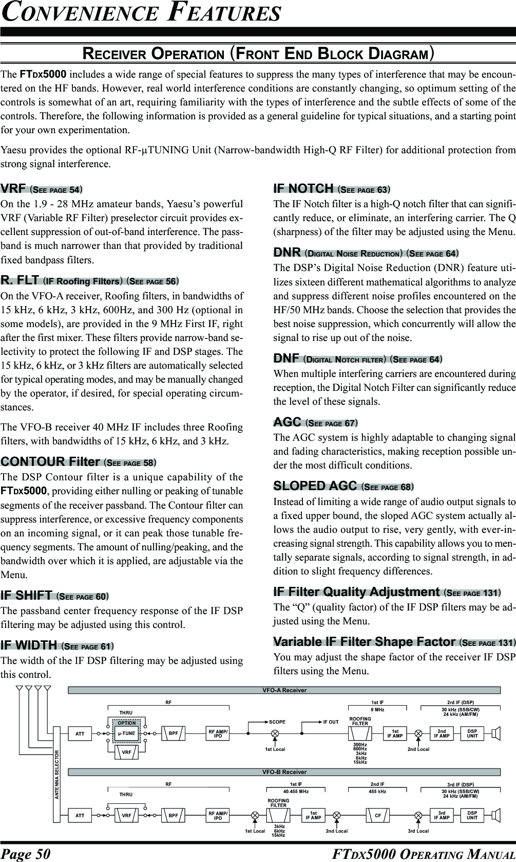
![Page 51FTDX5000 OPERATING MANUALIPO (INTERCEPT POINT OPTIMIZATION)The IPO feature allows the operator to optimize the characteristics of the receiver front end, depending on the current noiselevel and the strength of incoming signals.VFO-A IPO SetupPress the [A] button to activate VFO-A receiver (The[A] button will glow red).Move the [IPO] knob up or down to set the desiredcharacteristic of the VFO-A receiver front end, per thechart below.AMP1: Amplifies the incoming signal, using a lowdistortion RF preamplifier (normally, the IPOis set to this position).AMP2: Increases receiver sensitivity.IPO1: Improves the IPO.IPO2: Bypasses the RF preamplifier, yielding di-rect feed to the first mixer. As a result, theIPO is improved more.The selected receiver RF preamplifier will be indicatedin the IPO column of the Block Diagram Display.CONVENIENCE FEATURESVFO-B IPO SetupPress the [B] button to activate VFO-B receiver (The[B] button will glow orange).Move the [IPO] knob up or down to set the desiredcharacteristic of the VFO-B receiver front end, per thechart below.AMP1: Amplifies the incoming signal, using a lowdistortion RF preamplifier (normally, the IPOis set to this position).AMP2: Increases receiver sensitivity.IPO1: Improves the IPO.The selected receiver RF preamplifier will be indicatedin the IPO column of the Block Diagram Display.ADVICE:On the 10 MHz and lower bands, it generally is not necessary to use any preamplifier at all; selecting the “IPO” position asdescribed above will increase the strong-signal-handling capability of the receiver, and usually result in more pleasantreception due to reduced noise. If you can hear band noise with the preamplifiers disengaged, then a preamplifier is gener-ally not needed.[A] Button[IPO] Knob [B] Button[IPO] KnobPress the [IPO] knob briefly, to quickly set the IPO to“AMP1”.Press the [IPO] knob briefly, to quickly set the IPO to“AMP1”.AMP1IPO1IPO2AMPAMPAMP2IPO1IPO2IPO1AMP1AMPAMPAMP2](https://usermanual.wiki/Yaesu-Musen/20361X61.Users-Manual-1/User-Guide-1234776-Page-53.png)
![Page 52 FTDX5000 OPERATING MANUALATTEven with the IPO function on, extremely strong local signals or high noise can still degrade reception. In such situations,you can use the [ATT] button to insert 6, 12, or 18-dB of RF attenuation in front of the RF amplifier.VFO-A IPO SetupPress the [A] button to activate VFO-A receiver (The[A] button will glow red).Move the [ATT] knob up or down to set the desiredattenuation level of the VFO-A receiver, per the chartbelow.OFF: Attenuator is Off–6 dB: The incoming signal power is reduced by 6dB (Signal voltage reduced by 1/2)–12 dB: The incoming signal power is reduced by 12dB (Signal voltage reduced to 1/4)–18 dB: The incoming signal power is reduced by 18dB (Signal voltage reduced to 1/8)The selected attenuation level will be indicated in theATT column of the Block Diagram Display.VFO-B IPO SetupPress the [B] button to activate VFO-B receiver (The[B] button will glow orange).Move the [ATT] knob up or down to set the desiredattenuation level of the VFO-B receiver, per the chartbelow.OFF: Attenuator is Off–6 dB: The incoming signal power is reduced by 6dB (Signal voltage reduced by 1/2)–12 dB: The incoming signal power is reduced by 12dB (Signal voltage reduced to 1/4)–18 dB: The incoming signal power is reduced by 18dB (Signal voltage reduced to 1/8)The selected attenuation level will be indicated in theATT column of the Block Diagram Display.ADVICE:If background noise causes the S-meter to deflect on clear frequencies, move the [ATT] knob until the S-meter drops toabout “S-1”. This setting optimizes the trade-offs between sensitivity, noise, and interference immunity. Also, once youhave tuned in a station you want to work, you may want to reduce sensitivity further (or add more attenuation) by movingthe [ATT] knob to a greater setting. This reduces the strength of all signals (and noise) and can make reception morecomfortable, important especially during long QSOs. When looking for weak signals on a quiet band, you will want maxi-mum sensitivity, so the IPO should be disabled and the [ATT] knob should be set to “OFF” by pressing the [ATT] knob. Thissituation is typical during quiet times on frequencies above 21 MHz, and when using a small or negative-gain receivingantenna on other bands.To quickly restore full signal strength through the At-tenuator circuit, press the [ATT] knob in briefly to re-store the ATT display to the “OFF”.To quickly restore full signal strength through the At-tenuator circuit, press the [ATT] knob in briefly to re-store the ATT display to the “OFF”.[A] Button[ATT] Knob [B] Button[ATT] KnobCONVENIENCE FEATURES](https://usermanual.wiki/Yaesu-Musen/20361X61.Users-Manual-1/User-Guide-1234776-Page-54.png)
![Page 53FTDX5000 OPERATING MANUALCONVENIENCE FEATURESRF GAIN (SSB/CW/AM MODES)The RF Gain controls permit manual adjustment of the receiver RF and IF stages gain levels, to account for noise and/orsignal strength conditions.VFO-A Receiver RF GAIN AdjustmentThe (VFO-A)[RF GAIN] knob should, be rotated, initially,to the clockwise position. This is the point of maximumsensitivity, and counter-clockwise rotation will graduallyreduce the receiver RF gain.VFO-B Receiver RF GAIN AdjustmentThe VFO-B receiver RF Gain operates identically to theVFO-A receiver RF Gain.Press the (VFO-B)[RX] button to engage the DualReceive operation. The (VFO-B)[RX] button will glowgreen.Always utilize the fully clockwise position of the (VFO-B)[RF GAIN] knob as the starting point for operation.ADVICE:As the [RF GAIN] knob is rotated counterclockwiseto reduce the gain, the S-meter reading will rise. Thisindicates that the AGC voltage being applied to thereceiver is increasing (which causes a reduction in re-ceiver gain).Rotating the [RF GAIN] knob control to the fullycounter-clockwise position will essentially disable thereceiver, as the gain will be greatly reduced. In thiscase, as well, the S-meter will appear to be “pegged”against the right edge of the analog S-meter scale.The (VFO-B)[RF GAIN] knob operates identically tothe (VFO-A)[RF GAIN] knob. The effects of counter-clockwise rotation of the VFO-B receiver RF Gaincontrol may be observed visually on the VFO-B S-meter.QUICK POINT:Reception can often be optimized by rotating the [RFGAIN] knob slightly counter-clockwise, to the pointwhere the S-meter stationary needles position is justabout the same as the receiver noise level. This settingensures incoming signals will be heard with minimalnoise. The S/N (signal to noise) of the receiver will beimproved, without so much gain reduction that weaksignals cannot be heard.The RF GAIN control, along with the IPO and ATT(attenuator) features, all affect the system receiver gainin different ways. As a first step in dealing with highnoise or a crowded, high-level signal environment, theIPO generally should be the first feature engaged, ifthe frequency is low enough to allow the preamplifierto be bypassed. Thereafter, the RF GAIN and ATT (at-tenuator) features may be employed to provide pre-cise, delicate adjustment of the receiver, and fully op-timize performance.(VFO-A)[RF GAIN] Knob(VFO-B)[RF GAIN] Knob (VFO-B)[RX] Button](https://usermanual.wiki/Yaesu-Musen/20361X61.Users-Manual-1/User-Guide-1234776-Page-55.png)
![Page 54 FTDX5000 OPERATING MANUALThe FTDX5000 includes an unmatched array of RF selectivity-enhancing features. Please study the following materialcarefully, to understand the many interference tools and techniques completely.USING THE VRF (VARIABLE RF FRONT-END FILTER)The VRF system is a high-performance RF front-end preselector that has a high Q factor and low insertion loss. VRFprovides outstanding rejection of out-of-band signals, it can also significantly improve receiver performance when locatednear other transmitters, such as a contest or DX-pedition station. The FTDX5000 VRF system affects the 1.8 - 28 MHzamateur bands only.ADVANCED INTERFERENCE-SUPPRESSION FEATURES: RF FRONT ENDVFO-A VRF SetupPress the (VFO-A)[VRF] button. The button will glowred, and the “ ” icon will appear at the FLT col-umn of the Block Diagram Display. The VRF systemwill be engaged and centered on the currently operat-ing amateur band. The (VFO-A)[SELECT] knob willnow function as the VRF adjusting knob.VFO-B VRF SetupPress the (VFO-B)[RX] button to engage Dual Receiveoperation. The button will glow green.Press the (VFO-B)[VRF] button. The (VFO-B)[VRF]button will glows red, and the “ ” icon will appearat the FLT column of the Block Diagram Display. TheVRF system will be engaged and centered on the cur-rent operating amateur band. The (VFO-B)[SELECT]knob will now function as the VRF adjusting knob.(VFO-A)[SELECT] Knob[CLEAR] Button(VFO-A)[VRF/µ-T] Button(VFO-B)[SELECT] Knob[CLEAR] Button(VFO-B)[VRF] ButtonYou may rotate the (VFO-A)[SELECT] knob tochange the VRF system tuning, relative to your oper-ating frequency.ADVICE:You may observe the relative skew of the VRF sys-tem in the SUB DISPLAY-II . window.After moving the passband of the VRF systemmanually, you may re-center it on the current Ama-teur band by pressing the (VFO-A)[CLEAR] but-ton.To switch VRF off, press the (VFO-A)[VRF] buttonuntil the “ ” icon shows “ ” in the FLT col-umn of the Block Diagram Display; this confirms thatthe VRF circuit has been removed from the incomingreceived signal path.You may rotate the (VFO-B)[SELECT] knob tochange the VRF system tuning, relative to your oper-ating frequency.ADVICE:You may observe the relative skew of the VRF sys-tem in the SUB DISPLAY-III window.After moving the passband of the VRF systemmanually, you may re-center it on the current Ama-teur band by pressing the (VFO-B)[CLEAR] but-ton.To switch VRF off, press the (VFO-B)[VRF] button.The “ ” icon shows “ ” in the FLT column ofthe Block Diagram Display; this confirms that the VRFcircuit has been removed from the incoming receivedsignal path.](https://usermanual.wiki/Yaesu-Musen/20361X61.Users-Manual-1/User-Guide-1234776-Page-56.png)
![Page 55FTDX5000 OPERATING MANUALADVICE:The VRF system tuning is relatively broad, although itis still much narrower than the fixed bandpass filter.You may not hear much difference in the backgroundnoise or signal quality when you make minor adjust-ments. However, if you have receiving problems asso-ciated with a very strong signal, rotation of the [SE-LECT] knob may help reduce the strength of the inter-fering station, allowing improved reception of the de-sired signal, if receiver overload was degrading recep-tion.The VRF Filter operational status will be memorizedindependently on each VFO in the VFO stack.You may select the display pattern shown in the SUBDISPLAY window from three patterns via Menu item“019 DISP SELECT”. See page 122 for details.QUICK POINT:The VRF filter utilizes high-quality coils and capacitorsthat provide high Q, and yield a passband that is approxi-mately 20% to 30% the width of a traditional, fixedbandpass filter. As a result, significantly more “unwanted”signal rejection is provided. Within each amateur band,the following adjustment steps are provided, if you wishto skew the response in a particular direction to enhanceinterference rejection even more. The actual “sound” ofthe signal you are listening to will remain unchanged, how-ever.AMATEUR BAND1.8 MHz3.5 MHz5 MHz7 MHz10 MHz14 MHz18 MHz21 MHz24.5 MHz28 MHzVRF ADJUSTMENT STEPS62 steps62 steps62 steps62 steps30 steps30 steps20 steps20 steps20 steps20 stepsADVANCED INTERFERENCE-SUPPRESSION FEATURES: RF FRONT ENDUSING THE VRF (VARIABLE RF FRONT-END FILTER)](https://usermanual.wiki/Yaesu-Musen/20361X61.Users-Manual-1/User-Guide-1234776-Page-57.png)
![Page 56 FTDX5000 OPERATING MANUALR.FLT (ROOFING FILTERS)Narrow-band Roofing Filters of 15 kHz, 6 kHz, 3 kHz, 600 Hz, and 300 Hz bandwidths are provided in the first IF, rightafter the first mixer. These filters provide protection for the 2nd mixer, DSP, and other circuitry that follow. The roofingfilter can dramatically improve reception on a very crowded band (during a contest, etc.). Typically, the AUTO selectionmode is satisfactory for most operating situations, but in an extremely crowded phone or CW band you may wish to selecta narrower filter. For example, the 3 kHz roofing filter for SSB operation, or the 600 Hz filter for CW.:The 600 Hz roofing filter is only available on VFO-A. The 300Hz filter for VFO-A on the FTDX5000, is optional onother versions.INTERFERENCE REJECTION (SIGNALS OFF FREQUENCY BY JUST A FEW KHZ)VFO-A Roofing Filter SetupPress the [A] button (the button will glow red), to acti-vate the VFO-A receiver.Move the [R.FLT] knob up and down to set the de-sired bandwidth of the VFO-A Roofing Filter.The selected bandwidth of the Roofing Filter will beindicated in the R.FLT column of the Block DiagramDisplay.VFO-B Roofing Filter SetupPress the [B] button (the button will glow orange), toactivate the VFO-B receiver.Move the [R.FLT] knob up and down to set the de-sired bandwidth of the VFO-B Roofing Filter.The selected bandwidth of the Roofing Filter will beindicated in the R.FLT column of the Block DiagramDisplay.ADVICE:The Roofing Filter selection will be memorized inde-pendently on each VFO memory in the VFO stack.QUICK POINT:The AUTO mode Roofing Filter selections are shownbelow:AM/FM/FM-PKT: 15 kHzLSB/USB/PKT: 6 kHzCW/RTTY: 3 kHzPress the [R.FLT] knob in briefly, to quickly set theRoofing Filter to the “AUTO” selection. The filter willbe selected according to the operating mode. The indi-cated bandwidth will blink for three seconds in theRoofing Filter Display, and thereafter will appear con-tinuously. Typically, the filter will be set to “AUTO”,but may be easily changed when needed.Press the [R.FLT] knob in briefly, to quickly set theRoofing Filter to the “AUTO” selection. The filter willbe selected according to the operating mode. The indi-cated bandwidth will blink for three seconds in theRoofing Filter Display, and thereafter will appear con-tinuously. Typically, the filter will be set to “AUTO”,but may be easily changed when needed.TERMINOLOGY:A “Roofing Filter,” as its name implies, places a “Roof”over the receiver’s IF system bandwidth. This “Roof” pro-tects the circuitry downstream from strong signal over-load interference, just as a roof on a house protects thecontents from rain and snow.[A] Button[R.FLT] Knob [B] Button[R.FLT] Knob](https://usermanual.wiki/Yaesu-Musen/20361X61.Users-Manual-1/User-Guide-1234776-Page-58.png)
![Page 58 FTDX5000 OPERATING MANUALCONTOUR CONTROL OPERATIONThe Contour Filter system produces a gentle perturbation of the IF filter passband. The different frequency components ofthe signal can be suppressed or enhanced, thus improving the sound and/or readability of the received signal.INTERFERENCE REJECTION (SIGNALS WITHIN 3 KHZ)VFO-A Contour OperationPress the (VFO-A)[CONT/APF] button. The buttonwill glow red and the position of the “null” (or “Peak”)of the contour filter will be indicated in the SUB DIS-PLAY-II window. The (VFO-A)[SELECT] knob willnow function as the contour knob.Rotate the (VFO-A)[SELECT] knob to achieve themost pleasing audio reproduction of the incoming sig-nal.Press the (VFO-A)[CLEAR] button in briefly, toquickly move the “null” (or “Peak”) position to center.To cancel Contour tuning, press the (VFO-A)[CONT/APF] button once more.ADVICE:The contour filter null or peaking level may be adjustedusing Menu item “112 RDSP CNTR LV”. The factorydefault null setting is “–15” (dB).The bandwidth over which the contour null or peakingaffect is applied may be adjusted using Menu item “113RDSP CNTR WI”. The factory default setting is “10”.You may select the display pattern shown in the SUBDISPLAY window from three patterns via Menu item“019 DISP SELECT”. See page 122 for details.When the optional DMU-2000 Data Management Unitis connected, the Audio Scope (on the DMU-2000 “Os-cilloscope” page) is particularly useful when adjustingthe Contour controls. You can see the affect of theContour system on the signal levels, and the positionof the null/peak with respect to frequency componentsof interest. On the Audio Scope, you may visually ob-serve the affect of the Contour Controls while listen-ing to the signal, this will help build your intuition onhow best to use Contour tuning in the future.VFO-B Contour OperationPress the (VFO-B)[CONT/APF] button. The buttonwill glow red and the current “null” (or “Peak”) posi-tion of the contour filter will be indicated in the SUBDISPLAY-III window. The (VFO-B)[SELECT] knobwill now function as the contour knob.Rotate the (VFO-B)[SELECT] knob to achieve themost natural-sounding audio reproduction of the in-coming signal.Press the (VFO-B)[CLEAR] button in briefly, toquickly move the “null” (or “Peak”) position to center.To cancel Contour tuning, press the (VFO-A)[CONT/APF] button once more.(VFO-A)[SELECT] Knob (VFO-B)[SELECT] Knob(VFO-B)[CONT/APF] Button[CLEAR] Button(VFO-A)[CONT/APF] Button[CLEAR] ButtonQUICK POINT:When adjusted aggressively, the steep slopes of the DSPfiltering can impart an unnatural sound to an incoming sig-nal. Often, a narrow bandwidth is not the key to improvedcopy. The incoming signal itself may have undesirable orexcessive frequency components, especially in the low fre-quency range around 100-400 Hz. By judicious use of theContour filter, the “shoulder” of the passband responsemay be altered, or components removed from within thepassband, allowing the desired signal to rise above thebackground noise and interference in a manner not ob-tainable with other filtering systems.](https://usermanual.wiki/Yaesu-Musen/20361X61.Users-Manual-1/User-Guide-1234776-Page-60.png)
![Page 59FTDX5000 OPERATING MANUALCONTOUR CONTROL OPERATIONINTERFERENCE REJECTION (SIGNALS WITHIN 3 KHZ)Refer to Figure “B”, and notice the initial position ofthe contour when the [CONT] button is pushed. Ob-serve the “indentation” in the receiver passband wherethe contour filter is placing a low-Q “notch” (accord-ing to the setting of Menu item “112 RDSP CNTRLV”, as described on the previous page). Counter-clockwise rotation of the [SELECT](contour) knobcauses the indentation to move toward a lower fre-quency (to the left) within the passband, while clock-wise rotation causes the indentation to move toward ahigher frequency (to the right) within the passband. Byremoving the interference or unwanted frequency com-ponents on the incoming signal, it is possible to makethe desired signal rise out of the background noise/interference, and significantly enhance intelligibility.IFBANDWIDTHIFBANDWIDTHIFBANDWIDTHABC](https://usermanual.wiki/Yaesu-Musen/20361X61.Users-Manual-1/User-Guide-1234776-Page-61.png)
![Page 60 FTDX5000 OPERATING MANUALIF SHIFT OPERATION (SSB/CW/RTTY/PKT/AM MODES)The IF Shift allows you to vary the DSP filter passband higher or lower, (without changing the pitch of the incoming signal)to reduce or eliminate interference. Because the carrier tuning frequency is not varied, there is no need to re-tune theoperating frequency when using the IF Shift to eliminating the interference. The total passband tuning range for the IF Shiftsystem is ±1 kHz.INTERFERENCE REJECTION (SIGNALS WITHIN 3 KHZ)VFO-A IF SHIFT OperationPress the (VFO-A)[SHIFT] button. The center posi-tion of the IF passband will be indicated in the SUBDISPLAY-II window. The (VFO-A)[SELECT] knobwill now function as the IF SHIFT knob.Rotate the (VFO-A)[SELECT] knob to the left or rightto reduce the interference.Press the (VFO-A)[CLEAR] button in briefly toquickly move the filter passband to center. When thefilter passband is set to band center, the (VFO-A)[SHIFT] button will glow red.Refer to Figure “A” and notice the depiction of the IFDSP filter as a thick line in the center of the passband,no shift (the [SHIFT] button glows red). In Figure “B”,an interfering signal has appeared inside the originalpassband. In Figure “C”, you can see the effect of ro-tating the [SELECT](shift) knob and moving the fil-ter so that the interference is outside of the passband.VFO-B IF SHIFT OperationPress the (VFO-B)[SHIFT] button. The center posi-tion of the IF passband will be indicated in the SUBDISPLAY-III window. The (VFO-B)[SELECT] knobwill now function as the VFO-B IF SHIFT knob.Rotate the (VFO-B)[SELECT] knob to the left or rightto reduce the interference.Press the (VFO-B)[CLEAR] button in briefly toquickly move the filter passband to center. When thefilter passband is set to band center, the (VFO-B)[SHIFT] button will glow red.(VFO-A)[SELECT] Knob (VFO-B)[SELECT] Knob(VFO-B)[SHIFT] Button[CLEAR] Button(VFO-A)[SHIFT] Button[CLEAR] ButtonABCIFBANDWIDTHIFBANDWIDTHIFBANDWIDTHDesired Signal Desired Signal Desired SignalQRMQRMADVICE:You may select the display pattern shown in the SUB DIS-PLAY window from three patterns via Menu item “019DISP SELECT”. See page 122 for details.](https://usermanual.wiki/Yaesu-Musen/20361X61.Users-Manual-1/User-Guide-1234776-Page-62.png)
![Page 61FTDX5000 OPERATING MANUALWIDTH (IF DSP BANDWIDTH) TUNING (SSB/CW/RTTY/PKT MODES)The IF Width tuning system allows you to vary the width of the DSP IF filter passband, to eliminate interference. Moreover,the bandwidth may actually be expanded from its default setting, should you wish to enhance incoming signal fidelity wheninterference on the band is low.INTERFERENCE REJECTION (SIGNALS WITHIN 3 KHZ)VFO-A WIDTH OperationPress the (VFO-A)[WIDTH] button. The current band-width will appear in the SUB DISPLAY-II window.The (VFO-A)[SELECT] knob will now function asthe WIDTH knob.Rotate the (VFO-A)[SELECT] knob to the left or rightto reduce the interference.Press the (VFO-A)[CLEAR] button in briefly, to setthe bandwidth to default. When the bandwidth is set todefault, the (VFO-A)[WIDTH] button glows red.VFO-B WIDTH OperationPress the (VFO-B)[WIDTH] button. The current band-width will appear in the SUB DISPLAY-III window.The (VFO-B)[SELECT] knob will now function asthe WIDTH knob.Rotate the (VFO-B)[SELECT] knob to the left or rightto reduce the interference.Press the (VFO-B)[CLEAR] button in briefly, to setthe bandwidth to default. When the bandwidth is set todefault, the (VFO-B)[WIDTH] button glows red.Referring to Figure “B”, you can see the default band-width (the [WIDTH] button glows red).By rotating the [SELECT](width) knob to the left, thebandwidth will narrow (see Figure “A”). Rotation ofthe [SELECT](width) knob to the right, as depictedin Figure “C,” will widen the bandwidth.The default bandwidth, and total bandwidth adjustmentrange, will vary according to the operating mode andthe [NAR] button setting:(VFO-A)[SELECT] Knob (VFO-B)[SELECT] Knob(VFO-B)[WIDTH] Button[CLEAR] Button(VFO-A)[WIDTH] Button[CLEAR] ButtonADVICE:You may select the display pattern shown in the SUB DIS-PLAY window from three patterns via Menu item “019DISP SELECT”. See page 122 for details.OFF1.8 kHz - 4.0 kHz / 16 steps (2.4 kHz)500 Hz - 2.4 kHz / 7 steps (2.4 kHz)500 Hz - 2.4 kHz / 7 steps (500 Hz)500 Hz - 2.4 kHz / 7 steps (500 Hz)ON200 Hz - 1.8 kHz / 9 steps (1.8 kHz)50 Hz - 500 Hz / 10 steps (500 Hz)50 Hz - 500 Hz / 10 steps (300 Hz)50 Hz - 500 Hz / 10 steps (300 Hz)MODELSB/USBCWRTTY(LSB)PKT(LSB/USB)NAR SWITCH: Default (the [WIDTH] button glows red)IFBANDWIDTHIFBANDWIDTHIFBANDWIDTHABCNOTE:When rotating the [SELECT](WIDTH) knob counter-clockwise, the transition between 50 Hz and 25 Hz band-width may be accompanied by a “ping” sound, dependingon the amount of noise present. This is a normal condi-tion, and you should turn down the volume, when wearingheadphones, to minimize the amplitude of this momentarysound.](https://usermanual.wiki/Yaesu-Musen/20361X61.Users-Manual-1/User-Guide-1234776-Page-63.png)
![Page 62 FTDX5000 OPERATING MANUALINTERFERENCE REJECTION (SIGNALS WITHIN 3 KHZ)USING IF SHIFT AND WIDTH TOGETHER (SSB/CW/RTTY/PKT/AM MODES)The IF Shift and Variable IF Width features, together, form a very effective interference-fighting filter system.IFBANDWIDTHIFBANDWIDTHIFBANDWIDTHDesired Signal Desired Signal Desired SignalQRMQRMQRMQRMQRMQRMFor example, in Figure “A” you can see how interferencehas appeared both on the high and low sides of the desiredsignal. By pressing the [WIDTH] button (the button willglow red) and then rotating the [SELECT](width) knob,as shown in Figure “B”, the interference from one sidecan be eliminated, then press the [SHIFT] button to changethe function of the [SELECT] knob to the SHIFT knob(the [SHIFT] button glows red. However, the IF Widthadjustment is not changed). Now, by re-positioning the[SELECT](shift) knob (Figure “C”), the interference onthe opposite side can be removed, without re-introducingthe interference previously eliminated in Figure “B”.ADVICE:The Width and Shift features are the primary tools youshould use for best interference reduction. After narrow-ing the bandwidth (width) and/or adjusting the center ofthe passband (shift), the Contour control may also yieldfurther signal-enhancement benefits on the net residualbandwidth. Additionally, the IF Notch Filter (see the nextsection) may be utilized, in conjunction with the three otherfilter systems, to significant advantage.ABC](https://usermanual.wiki/Yaesu-Musen/20361X61.Users-Manual-1/User-Guide-1234776-Page-64.png)
![Page 63FTDX5000 OPERATING MANUALINTERFERENCE REJECTION (SIGNALS WITHIN 3 KHZ)IF NOTCH FILTER OPERATION (SSB/CW/RTTY/PKT/AM MODES)The IF Notch filter is a highly effective system that allows you to slice out an interfering beat note or other carrier signalfrom inside the receiver passband.VFO-A IF Notch OperationPress the (VFO-A)[NOTCH] button. The (VFO-A)[NOTCH] button glows red, and the current “null”(or “Peak”) position of the IF notch filter will appearin the SUB DISPLAY-II window. The (VFO-A)[SELECT] knob will now function as the notchadjustment knob.Rotate the (VFO-A)[SELECT] knob to adjust the cen-ter frequency of the IF notch filter.Press the (VFO-A)[CLEAR] button to move the “null”position to center.To switch the IF notch filter off, press the (VFO-A)[NOTCH] button once more.The affect of rotation of the [SELECT](notch)knob on the performance of the IF notch filter isdepicted in Figure “A”. In Figure “B”, you can seethe notching effect of the IF notch filter as you ro-tate the [SELECT](notch) knob to eliminate theincoming interference.VFO-B IF Notch OperationPress the (VFO-B)[NOTCH] button. The (VFO-B)[NOTCH] button glows red, and current “null” (or“Peak”) position of the IF notch filter will be indicatedin the SUB DISPLAY-III window. The (VFO-B)[SELECT] knob will now function as the notchadjustment knob.Rotate the (VFO-B)[SELECT] knob to adjust the cen-ter frequency of the IF notch filter.Press the (VFO-B)[CLEAR] button to move the “null”position to center.To switch the IF notch filter off, press the (VFO-B)[NOTCH] button once more.ADVICE:The width of the IF notch null may be adjusted usingMenu item “110 RDSP NOTCH WI”. Both “Wide”and “Narrow” selections are available, with “Narrow”providing the least disruption of the “desired” signal.You may select the display pattern shown in the SUBDISPLAY window from three patterns via Menu item“019 DISP SELECT”. See page 122 for details.When the optional DMU-2000 Data Management Unitis connected, the effect of the IF notch filter may beobserved using the Audio Scope (on the “Oscilloscope”page). The notch will be seen as a “dip” in the noiseplatform observed. What’s more, the “Waterfall” dis-play may be used to observe the effect of the IF notchfilter, which will appear as a white area in the coloredbackground. The tuning rate for the IF notch is some-what slow while you adjust the [SELECT](notch)knob, so the use of the Waterfall display to confirmproper adjustment is highly recommended.(VFO-A)[SELECT] Knob[CLEAR] Button(VFO-A)[NOTCH] Button(VFO-B)[SELECT] Knob[CLEAR] Button(VFO-B)[NOTCH] ButtonIFBANDWIDTHQRM(Heterodyne)QRM(Heterodyne)IFBANDWIDTHDesired Signal Desired SignalAB](https://usermanual.wiki/Yaesu-Musen/20361X61.Users-Manual-1/User-Guide-1234776-Page-65.png)
![Page 64 FTDX5000 OPERATING MANUALDIGITAL NOISE REDUCTION (DNR) OPERATIONThe Digital Noise Reduction (DNR) system is designed to reduce the level of random noise found on the HF and 50 MHzbands. It is especially effective during SSB operation. By rotating the [DNR] knob, any of 15 different noise-reductionalgorithms can be selected; each of these algorithms was created for dealing with a different noise profile, and you will wantto experiment with the DNR system to find the best setting according to the noise currently being experienced.INTERFERENCE REJECTION (SIGNALS WITHIN 3 KHZ)VFO-A DNR OperationPress the (VFO-A)[DNR] button. The button will glowred, and the current noise-reduction algorithm will ap-pear in the SUB DISPLAY-II window. The (VFO-A)[SELECT] knob will now function as the notchadjustment knob.Rotate the (VFO-A)[SELECT] knob to select the set-ting that most effectively reduces the noise level.Press the (VFO-A)[CLEAR] button to set the noise-reduction algorithm to default.To switch the DNR system off, press the (VFO-A)[NOTCH] button once more.DIGITAL NOTCH FILTER (DNF) OPERATIONThe Digital Notch Filter (DNF) is an effective beat-canceling filter that can null out a number of interfering beat notesinside the receiver passband. Because this is an Auto-Notch feature, there is no adjustment knob associated with this filter.ADVICE:If a very strong interfering carrier is encountered, we recommend you first use the IF notch filter, as it is the most effectivenotching tool in the receiver section.VFO-A DNF OperationPress the (VFO-A)[DNF] button. The button glows red,confirming that the DNF system is engaged.To switch the DNF system off, press the (VFO-A)[DNF] button once more.VFO-B DNR OperationPress the (VFO-B)[DNR] button. The (VFO-B)[DNR]button glows red, and the current noise-reduction al-gorithm will appear in the SUB DISPLAY-II window.The (VFO-B)[SELECT] knob will now function asthe notch adjustment knob.Rotate the (VFO-B)[SELECT] knob to select the set-ting that most effectively reduces the noise level.Press the (VFO-B)[CLEAR] button to set the noise-reduction algorithm to default.To switch the DNR system off, press the (VFO-B)[NOTCH] button once more.(VFO-A)[SELECT] Knob (VFO-B)[SELECT] Knob(VFO-B)[DNR] Button[CLEAR] Button(VFO-A)[DNR] Button[CLEAR] Button(VFO-A)[DNF] Button (VFO-B)[DNF] ButtonVFO-A DNF OperationPress the (VFO-B)[DNF] button. The button glowsred, confirming that the DNF system is engaged.To switch the DNF system off, press the (VFO-B)[DNF] button once more.ADVICE:You may select the display pattern shown in the SUB DIS-PLAY window from three patterns via Menu item “019DISP SELECT”. See page 122 for details.](https://usermanual.wiki/Yaesu-Musen/20361X61.Users-Manual-1/User-Guide-1234776-Page-66.png)
![Page 65FTDX5000 OPERATING MANUALINTERFERENCE REJECTION (SIGNALS WITHIN 3 KHZ)NARROW (NAR) ONE-TOUCH IF FILTER SELECTIONVFO-B “One-Touch Narrow” OperationPress the [B] button (the button glows orange).Pressing the [NAR] button engages a narrow IF DSPfilter, specific to the mode in use, and not related to thesetting of the [WIDTH] knob.Pressing the [NAR] button once more returns band-width control to the Width/Shift system. The factorydefault settings of the bandwidth are as shown in thetable below.ADVICE:When the narrow bandwidth is selected, the “ ” iconwill appear in the display, and the bandwidth on the SUBDISPLAY-III will be reduced, (if the SUB DISPLAY-IIIwindow indicates the bandwidth).VFO-A “One-Touch Narrow” OperationPress the [A] button to activate VFO-A (the button willglow red).Pressing the [NAR] button engages a narrow IF DSPfilter, specific to the mode in use, and not related to thesetting of the [WIDTH] knob.Pressing the [NAR] button once more returns the band-width control to the Width/Shift system. The factorydefault of the bandwidth is as shown below.ADVICE:When the narrow bandwidth is selected, the “ ” iconwill appear in the display, and the bandwidth depiction inthe SUB DISPLAY-II window will be narrowed (if SUBDISPLAY-II window is showing the bandwidth).[A] Button [B] Button[NAR] Button [NAR] ButtonOFF2.4 kHz (1.8 kHz - 4.0 kHz / 16 steps)2.4 kHz (500 Hz - 2.4 kHz / 7 steps)500 Hz (500 Hz - 2.4 kHz / 7 steps)500 Hz (500 Hz - 2.4 kHz / 7 steps)25 kHz (±5.0 kHz Deviation)9 kHz25 kHz (±5.0 kHz Deviation)ON1.8 kHz (200 Hz - 1.8 kHz / 9 steps)500 Hz (50 Hz - 500 Hz / 10 steps)300 Hz (50 Hz - 500 Hz / 10 steps)300 Hz (50 Hz - 500 Hz / 10 steps)12.5 kHz (±2.5 kHz Deviation)6 kHz12.5 kHz (±2.5 kHz Deviation)MODELSB/USBCWRTTY(LSB)PKT(LSB/USB)PKT(FM)AMFMNAR BUTTONADVICE:You may select the display pattern shown in the SUB DIS-PLAY window from three patterns via Menu item “019DISP SELECT”. See page 122 for details.](https://usermanual.wiki/Yaesu-Musen/20361X61.Users-Manual-1/User-Guide-1234776-Page-67.png)
![Page 66 FTDX5000 OPERATING MANUALIF NOISE BLANKER (NB) OPERATIONThe FTDX5000 includes an effective IF Noise Blanker, which can significantly reduce pulse noise like that caused byautomotive ignition systems.VFO-A NB OperationPress the [A] button (the button glows red), if neededto enable VFO-A.Press the [NB] button briefly to reduce short durationpulse noise such as from switching transients, auto-mobile ignitions and power lines. The “ ” icon willappear in the display to confirm that the Narrow-NB isoperating.Press the [NB] button again to reduce longer-dura-tion man-made pulse noise. The “ ” icon willblink for three seconds, and thereafter will appear con-tinuously, to confirm that the Wide-NB is operating.Rotate the (VFO-A)[NB] knob to the point where theoffending noise is best reduced or eliminated.To end Noise Blanker operation, press the [NB] but-ton once more. The “ ” (or “ ”) icon willturn off, confirming that the Noise Blanker is no longerin operation.INTERFERENCE REJECTION (SIGNALS WITHIN 3 KHZ)VFO-B NB OperationPress the [B] button (the [B] button glows orange).Press the [NB] button briefly to reduce short durationpulse noise such as from switching transients, auto-mobile ignitions and power lines. The “ ” icon willappear in the display to confirm that the Narrow-NB isoperating.Press the [NB] button again to reduce longer-dura-tion man-made pulse noise. The “ ” icon willblink for three seconds, and thereafter will appear con-tinuously, to confirm that the Wide-NB is operating.Rotate the (VFO-B)[NB] knob to the point where theoffending noise is best reduced or eliminated.To end Noise Blanker operation, press the [NB] but-ton once more. The “ ” (or “ ”) icon will turnoff, confirming that the Noise Blanker is no longer inoperation.[A] Button [NB] Knob [B] Button [NB] Knob(VFO-A)[NB] Knob (VFO-B)[NB] Knob](https://usermanual.wiki/Yaesu-Musen/20361X61.Users-Manual-1/User-Guide-1234776-Page-68.png)
![Page 67FTDX5000 OPERATING MANUALAGC (AUTOMATIC GAIN CONTROL)The AGC system is designed to help compensate for fading and other propagation effects, with characteristics that can beof particular value on each operating mode. The basic objective of AGC is to maintain a constant audio output level oncea certain minimum threshold of signal strength is achieved.VFO-A AGC SelectionPress the [A] button briefly to enable VFO-A (the LEDin the [A] button will glow red).Move the [AGC] knob up or down to set the desiredreceiver recovery time constant of the VFO-A receiver.The selected recovery time will be indicated in the AGCcolumn of the Block Diagram Display.Hold the [AGC] knob up or down for two seconds todisable the AGC (for testing or weak-signal reception).For most operations, we recommend using the “AUTO”mode by pressing the [AGC] knob in briefly, or mov-ing the [AGC] knob to set the ATT display to the“AUTO” position.VFO-B AGC SelectionPress the [B] button (the [B] button glows orange).Move the [AGC] knob up and down to set the desiredreceiver recovery time constant of the VFO-A receiver.The selected recovery time will be indicated in the AGCcolumn of the Block Diagram Display.Hold the [AGC] knob up or down for two seconds todisable the AGC (for testing or weak-signal reception).For most operations, we recommend using the “AUTO”mode by pressing the [AGC] knob in briefly, or mov-ing the [AGC] knob to set the ATT display to the“AUTO” position.TOOLS FOR COMFORTABLE AND EFFECTIVE RECEPTIONNOTE:When the AGC receiver recovery time is set to “OFF”,the S-meter will no longer deflect. Additionally, youwill likely encounter distortion on stronger signals, asthe IF amplifiers and the following stages are prob-ably being overloaded.Normally, the AGC “AUTO” selection is satisfactoryfor most situations, but in the event of operation on acrowded band where you wish to receive a weak sig-nal, you may change the setting (to “FAST”, for ex-ample). The AGC “AUTO” mode selections are:[A] Button[AGC] Knob[B] Button[AGC] KnobADVICE:When a received signal becomes degraded due to pulsetype noise, you may improve signal readability by settingMenu items “002 AGC FST HLD”, “004 AGC MIDHLD”, and “006 AGC SLW HLD” to “0 msec”.QUICK POINTSeveral aspects of AGC performance may be configuredvia the Menu. However, because AGC can have such aprofound impact on overall receiver performance, we gen-erally do not recommend any changes to the AGC Menuselections until you are thoroughly familiar with the per-formance of the FTDX5000.TERMINOLOGY:Automatic Gain Control, or AGC, is a circuit that sensesthe incoming signal strength, and then limits the gains ofthe RF and IF stages, to maintain the output audio volumeat a more-or-less constant level. AGC also protects theRF, IF, Audio, and DSP stages from overload, by limitingthe signal strength applied to circuits, regardless of theinput signal level.OPERATING MODELSBUSBCWAMFMRTTYPKT (FM)PKT (LSB)AUTO AGC SELECTIONSLOWSLOWFASTFASTFASTSLOWFASTSLOW](https://usermanual.wiki/Yaesu-Musen/20361X61.Users-Manual-1/User-Guide-1234776-Page-69.png)
![Page 68 FTDX5000 OPERATING MANUALTOOLS FOR COMFORTABLE AND EFFECTIVE RECEPTIONAGC (AUTOMATIC GAIN CONTROL)SLOPED AGC OperationIn traditional AGC systems, the audio output from the transceiver becomes essentially constant, once the thresholdfor AGC action is reached (usually several dozen dB above the no-signalnoise floor). The FTDX5000, however, includes an innovative Sloped AGCsystem on the VFO-A receiver that allows the audio volume to rise and fallslightly according to signal strength. Although the rise/fall slope is not dra-matic, it is sufficient to allow you to use your ear to discern and separatesignals according to signal strength, not just audio frequency.NORMALInput SignalAudio OutputSLOPEDUsing Sloped AGC1. Press the [MENU] button briefly to enter the Menumode.2. Use the (VFO-A)[SELECT] knob to select Menuitem “107 ROUT AGC SLP”.3. Rotate the (VFO-B)[SELECT] knob to change thesetting to “SLOPE”.4. Press and hold in the [MENU] button for two sec-onds to save the new setting and exit to normal op-eration. You will now be using the Sloped AGCsystem.(VFO-B)[SELECT] Knob[MENU] Button(VFO-A)[SELECT] Knob](https://usermanual.wiki/Yaesu-Musen/20361X61.Users-Manual-1/User-Guide-1234776-Page-70.png)
![Page 69FTDX5000 OPERATING MANUALMUTE FEATURE (VFO-A BAND)TOOLS FOR COMFORTABLE AND EFFECTIVE RECEPTIONThere may be occasions during Dual Receive operationwhen you want to silence the VFO-A receiver temporarily,to concentrate on the signal being received on the VFO-Breceiver. The Mute feature makes this simple to accom-plish.Press the (VFO-A)[RX] button briefly, located to the up-per left of the Main Tuning Dial knob. The VFO-A re-ceiver will be silenced, and the green LED in the (VFO-A)[RX] button will blink.To restore reception on the VFO-A receiver, just press theblinking (VFO-A)[RX] button once more.ADVICE:If you press the [POWER] switch briefly while the trans-ceiver is turned on, the transceiver audio will be muted forthree seconds.[A] Button[POWER] SwitchADJUSTABLE RECEIVER AUDIO FILTERThe FTDX5000 includes a adjustable receiver audio filter, that provides precise, independent control of the low- and upper-ranges.1. Press the [MENU] button briefly, to enter the Menumode.2. Rotate the (VFO-A)[SELECT] knob to find Menuitems “047” through “050”; these parameters apply tothe adjustment of the receiver audio filter in the AMmode, Menu items “053” through “056” apply to theadjustment of the RX audio filter in the CW mode,Menu items “075” through “078” apply to the adjust-ment of the RX audio filter in the FM mode, Menuitems “089” through “092” apply to the adjustment ofthe RX audio filter in the RTTY mode, and Menu items“099” through “102” apply to the adjustment of theRX audio filter in the SSB mode.3. Rotate the (VFO-B)[SELECT] knob to perform ad-justments to a particular Menu item.You may confirm the change of the sound quality fromthe speaker or headphones.4. When you have completed all adjustments, press andhold in the [MENU] button for two seconds to savethe new settings and exit to normal operation. If youonly press the [MENU] button momentarily to exit,any changes you performed will not be stored.AM 047 A3E LCUT FRQ OFF / 100 (Hz) ~ 1000 (Hz)048 A3E LCUT SLP 6dB/oct or 18dB/oct049 A3E HCUT FRQ 700 (Hz) ~ 4000 (Hz) / OFF050 A3E HCUT SLP 6dB/oct or 18dB/octCW 053 A1A LCUT FRQ OFF / 100 (Hz) ~ 1000 (Hz)054 A1A LCUT SLP 6dB/oct or 18dB/oct055 A1A HCUT FRQ 700 (Hz) ~ 4000 (Hz) / OFF056 A1A HCUT SLP 6dB/oct or 18dB/octFM 075 F3E LCUT FRQ OFF / 100 (Hz) ~ 1000 (Hz)076 F3E LCUT SLP 6dB/oct or 18dB/oct077 F3E HCUT FRQ 700 (Hz) ~ 4000 (Hz) / OFF078 F3E HCUT SLP 6dB/oct or 18dB/octRTTY 089 RTTY LCUT FRQ OFF / 100 (Hz) ~ 1000 (Hz)090 RTTY LCUT SLP 6dB/oct or 18dB/oct091 RTTY HCUT FRQ 700 (Hz) ~ 4000 (Hz) / OFF092 RTTY HCUT SLP 6dB/oct or 18dB/octSSB 099 A3J LCUT FRQ OFF / 100 (Hz) ~ 1000 (Hz)100 A3J LCUT SLP 6dB/oct or 18dB/oct101 A3J HCUT FRQ 700 (Hz) ~ 4000 (Hz) / OFF102 A3J HCUT SLP 6dB/oct or 18dB/oct(VFO-B)[SELECT] Knob[MENU] Button(VFO-A)[SELECT] Knob](https://usermanual.wiki/Yaesu-Musen/20361X61.Users-Manual-1/User-Guide-1234776-Page-71.png)
![Page 70 FTDX5000 OPERATING MANUAL1. The operating mode is se-lected using the [MODE]buttons. The VFO (A or B)to which the selection is ap-plied is selected by the [A]or [B] button located to theupper left of the MainTuning Dial knob. Usu-ally, the [A] buttonglows red, signifyingthat VFO-A is being ad-justed. Similarly, press-ing the [B] button willcause the [B] button toglow orange, signifying VFO-B adjustment. Press the[A] or [B] button to select the desired VFO. Then pressthe [LSB] or [USB] button briefly to select one of theSSB modes. For AM operation, press the [AM/FM]button repeatedly until the “ ” icon appears in thedisplay.QUICK POINT:By convention, LSB is used in the 7 MHz and lowerAmateur bands for SSB communication, and USB isused on the 14 MHz and higher bands (the 10 MHzband is used for CW and data modes only).2. Rotate the Main Tuning Dial knob to adjust the oper-ating frequency. Alternatively, you may use the [UP]/[DWN] scanning buttons on the MH-31B8 Hand Mi-crophone to sweep up or down the current band.3. Press the microphone’s PTT (Push To Talk) switch tobegin transmission; speak into the microphone in anormal voice level.ADVICE:The “ ” indicator will light up in the frequencydisplay area, confirming that transmission is inprogress.When transmitting in the AM mode, rotate the [RFPWR] knob to set a maximum (carrier) power out-put of 50 Watts.4. In the SSB mode, adjust the micro-phone amplifier gain to match themicrophone and your voice level.set the [METER] switch to the“ALC” position and close the PTTswitch. Speak into the microphone ina normal voice level, and adjust the[MIC] (gain) knob so that the ALCvoltage stays within the blue ALCzone of the meter (up to 2/3 of fullscale deflection) on voicepeaks.ADVICE:The microphone gain ofthe AM mode has been programmed at the factoryto a level that should be satisfactory for most situ-ations. However, using Menu item “051 A3E MICGAIN”, you may set a different fixed value, orchoose the “MCVR” option, which then lets youuse the front panel [MIC] knob to set the micro-phone gain in the AM mode. In this case, the [MIC]knob should not be advanced to the point wherethe ALC meter deflects. In many cases, the samesetting used on SSB will be satisfactory.The relative Microphone Gain level will show for3 seconds in the lower right corner of the MainDisplay whenever the inner [MIC] knob is turned.Alternately, the 3-second display feature may bechanged to show in the SUB DISPLAY-III win-dow via Menu item “018 DISP INDI”. Addition-ally, you may disable the 3-second display featurevia Menu item “017 DISP LVL IND” See page122 for details.5. Release the PTT switch at the end of your transmis-sion. The transceiver will return to the receive mode.SSB/AM MODE TRANSMISSIONMain Tuning Dial knob[METER] Switch [B] Button[MOX] Button[MODE] Buttons[MIC] Knob[RF PWR] Knob[A] Button](https://usermanual.wiki/Yaesu-Musen/20361X61.Users-Manual-1/User-Guide-1234776-Page-72.png)
![Page 71FTDX5000 OPERATING MANUALSSB/AM MODE TRANSMISSIONADVICE:ALC meter deflection may be caused by excessive drivepower, and also by reflected power detected in the an-tenna system. If the impedance presented to the trans-ceiver is other than 50 Ohms, the ALC meter actionobserved may not be related to the proper setting ofthe [MIC] (gain) knob. Therefore, we recommend thatyou make [MIC] gain adjustments into a dummy loador an antenna system presenting an impedance veryclose to 50 Ohms.Rotate the [RF PWR] knob to set the desired poweroutput. Clockwise rotation of the [RF PWR] knob willincrease the power. The adjustmentrange is between 10 Watts and 200Watts, and you should always use theminimum power necessary for main-taining reliable communications.The RF Power Output will show for 3 seconds in thelower right corner of the Main Display whenever theouter [RF PWR] knob is turned.Alternately, the 3-second display feature may bechanged to show in the SUB DISPLAY-III windowvia Menu item “018 DISP INDI”. Additionally, youmay disable the 3-second display feature via Menu item“017 DISP LVL IND” See page 122 for details.The analog PO meter indicates the average power out-put level. SSB transmit average talk power is normally10% to 50% of the peak power output. Voice charac-teristics, microphone qualities, parametric equalizerand compression settings affect actual talk power out-put.When performing transmitter tests for setup of the[MIC] or [RF PWR] knobs, be sure to monitor thefrequency before transmitting, to avoid interference toothers who may already be using the frequency.Four techniques for initiating Transmit/Receive con-trol are provided on the FTDX5000. You may choosethe technique(s) that best suit your operating needs:Pressing the microphone PTT switch will engagethe transmitter.The rear panel PTT jack may be connected to afoot switch or other manual switching device inorder to engage the transmitter.Pressing the front panel [MOX] button will lockthe transmitter on. Press the [MOX] button againto return to receive.The VOX (Voice Operated Xmit) circuit will en-gage the transmitter automatically when you speakinto the microphone. For VOX operation details,see page 81.](https://usermanual.wiki/Yaesu-Musen/20361X61.Users-Manual-1/User-Guide-1234776-Page-73.png)
![Page 72 FTDX5000 OPERATING MANUALThe Automatic Antenna Tuner (“ATU”) built into each FTDX5000 is crafted to ensure a 50-Ohm load for the final amplifierstage of the transmitter. We recommend the ATU be used whenever you operate the FTDX5000.ADVICE:The ATU of the FTDX5000, being located inside the station, only adjusts the impedance presented to the transmitter atthe station end of your coaxial cable feedline. It does not “tune” the SWR at the antenna feedpoint itself. When design-ing and building your antenna system, we recommend that every effort be made to ensure a low SWR at the antennafeedpoint.The ATU of the FTDX5000 includes 100 memories for tuning data. Eleven of these memories are allocated, one perAmateur band, so that each band has at least one setting preset for use on that band. The remaining 89 memories arereserved for the 89 most-recent tuning points, allowing quick frequency change without the need to retune the ATU.The ATU in the FTDX5000 is designed to match impedances within the range of 16.5 Ohms to 150 Ohms, correspond-ing to an SWR of 3:1 or less on the HF amateur bands (6 meter amateur band: 25 Ohms to 100 Ohms, corresponding toan SWR of 2:1 or less). Accordingly, simple non-resonant whip antennas, along with random-length wires and the“G5RV” antenna (on most bands) may not be within the impedance matching range of the ATU.ATU OPERATIONUSING THE AUTOMATIC ANTENNA TUNER1. Rotate the [RF PWR] knob fully clockwise (to theright).2. Use the Main Tuning Dial knob to set the radio to thedesired operating frequency within the Amateur band.3. Press the [TUNE] button briefly to place the ATU inthe transmit line (no adjustment/tuning will occur yet).The “ ” icon will appear in the display.QUICK POINT:The brief press of the [TUNE] button will turn the tuneron, and the microprocessor will automatically selectthe tuning point closest to the current operating fre-quency.4. Press and hold in the [TUNE] button for two secondsto begin automatic tuning. The transmitter will be en-gaged, and the “ ” icon will blink while tuning isin progress. When the optimum tuning point has beenreached, the radio will return to receive, and the“” icon will again glow steadily (instead ofblinking).5. While tuning around the band using the Main TuningDial knob, you will observe that the “ ” iconblinks momentarily every 10 kHz. This momentaryblinking indicates that a new tuning window has beenentered. If you want to save tuning data associated witheach 10 kHz window, repeat step 4 (above) for each ofthe windows. On bands like 1.8 MHz where the im-pedance may change rapidly, the storage of a numberof tuning points is recommended.6. To disconnect the ATU from the transmit line, pressthe [TUNE] button briefly. The “ ” icon will turnoff, confirming that the ATU has been turned off. Inthe “Off” mode, the transceiver will be directly con-nected to the coaxial cable connected to your antenna,and it will operate based on whatever impedance ispresent at the station end of the coax.ADVICE:The ATU circuit is located between the final amplifier andthe rear-panel antenna jack; reception is not affected bythe ATU.QUICK POINT:As shipped from the factory, only one ATU alignmentpoint is saved on each Amateur band. This was memo-rized during the final alignment and performance veri-fication stages on the production line.The momentary flickering of the “ ” icon occurswhenever you cross over into a new 10 kHz ATUmemory window.NOTE:Please check the operating frequency before beginning thetuning process, to be sure you are not interfering with oth-ers who may already be using the frequency.TERMINOLOGY:Antenna Tuner Memories: The microprocessor of the ATUmakes a note of the positions of the tuning capacitors andthe selected inductors, and stores the data for each 10 kHzwindow in which tuning has occurred. This eliminates theneed to re-tune every time you return to a frequency onwhich you already have completed the tuning process.[TUNE] Button[RF PWR] Knob](https://usermanual.wiki/Yaesu-Musen/20361X61.Users-Manual-1/User-Guide-1234776-Page-74.png)
![Page 73FTDX5000 OPERATING MANUALABOUT ATU OPERATIONFigure 1 depicts a situation where normal tuning of the ATU has been successfully completed, and the tuning data has beenstored in the ATU memory. The antenna system as seen by the transmitter is shown.In Figure 2, the operator has changed frequency, and the “ ” icon is shown. The operator presses and holds in the[TUNE] button for two seconds to begin impedance matching using the ATU.If a high SWR condition exists (above 3:1), corrective action must be taken in the antenna system to bring the impedancecloser to 50 Ohms. The ATU will refuse to memorize settings on frequencies where the SWR exceeds 3:1. The high SWRmay indicate a mechanical failure in the antenna or feed system, and such failures can lead to the generation of spurioussignals causing TVI, etc.About ATU MemoriesSWR (Post-tuning) Less than 1.5:1The tuning settings are committed to the ATU memory.SWR (Post-tuning) Greater than 1.5:1Tuning data will not be retained in memory. If you return to the same frequency, the tuning process must be repeated.SWR (Post-tuning) Greater than 3:1The “ ” icon will light up, and tuning settings, if achieved, will not be memorized. Please investigate andresolve the high SWR condition before attempting further operation using this antenna.USING THE AUTOMATIC ANTENNA TUNERSWR: 2.0FrequencySWR: 1.5Feed Point SWRSWR after ATU TuningSWR: 1.0FIGURE 1FIGURE 2SWR: 3.0SWR: 3.0FrequencySWR: 2.0Memorized ATU TuningRetuned SettingSWR: 1.0The “ ” icon appears on the displaywhen you transmit on this frequency](https://usermanual.wiki/Yaesu-Musen/20361X61.Users-Manual-1/User-Guide-1234776-Page-75.png)