Yaesu Musen 20361X61 HF Transceiver with Scanning Receiver User Manual P65
Yaesu Musen Co., Ltd. HF Transceiver with Scanning Receiver P65
UserManual.wiki
>
Yaesu Musen
>
20361X61 User Manual
>
Users Manual 2
Contents
1.
Users Manual 1
2.
Users Manual 2
Users Manual 2
Navigation menu
Upload a User Manual
Namespaces
Wiki Guide
HTML
PDF
Info
Views
User Manual
Discussion / Help
Navigation
![Page 74 FTDX5000 OPERATING MANUALPARAMETRIC MICROPHONE EQUALIZER (SSB/AM/FM MODES)The FTDX5000 includes a unique Three-Band Parametric Microphone Equalizer, that provides precise, independent con-trol over the low-, mid-, and treble-ranges in your voice waveform. You may utilize one group of settings when the speechprocessor is off, and an another independent group of settings when the speech processor is on.Setup of the Parametric Microphone Equalizer1. Connect the microphone to the MIC jack.2. Set the [RF PWR] knob to its minimum value, to re-duce interference to other users during adjustment.ADVICE:We recommend you consider connecting a dummyload to one of the Antenna jacks, and monitor yoursignal on a separate receiver, to prevent interfer-ence to other users.You will have the best chance of hearing the ef-fects of adjustments if you wear headphones (con-nected to the monitor receiver) while monitoringyour transmitted signal.3. To adjust the Parametric Microphone Equalizer whilethe speech processor is disabled, press the [PROC]button until the “ ” icon appears (or blinks) inthe display. To adjust the Parametric MicrophoneEqualizer with the speech processor engaged, press the[PROC] button until the “ ” and “ ” iconappears in the display.ADVICE:A blinking “ ” icon indicates the ParametricMicrophone Equalizer menu settings have all been setto “OFF”, as described later.4. Press the [MONI] button, if you want to listen on theFTDX5000’s internal monitor. Adjust the monitor levelusing the [MONI] knob.5. Press the [MENU] button briefly. The Menu list willappear in the display.6. Rotate the (VFO-A)[SELECT] knob to find the“TAUD” Menu area, which contains Menu items “151”through “159”; these parameters apply to the adjust-ment of the Parametric Microphone Equalizer whenthe speech processor is disabled. Menu items “160”through “168” apply to the adjustment of the Paramet-ric Microphone Equalizer when the speech processoris engaged.7. Rotate the (VFO-B)[SELECT] knob to perform ad-justments to a particular Menu item.8. Press the PTT switch, and speak into the microphonewhile listening to the effects of the changes you aremaking (in step 6). Because the overall effect on thesound will change with each adjustment you make, youshould make several passes through each adjustmentarea, to be sure that you are achieving the optimumsetting.9. When you have completed all adjustments, press andhold in the [MENU] button for two seconds to savethe new settings and exit to normal operation. If youonly press the [MENU] button momentarily to exit,any changes you performed will not be stored.ADVICE:To roll off excessive bass response in a wide-range studiomicrophone, try putting a 10 dB null at 100 Hz with abandwidth of “1” or “2,” do about a 3 dB null centered on800 Hz with a bandwidth of “3,” and then put an 8 dBpeak centered on 2100 Hz with a bandwidth of “1.” Theseare starting recommendations; each microphone and user’svoice will be different, often requiring different settings.(VFO-B)[SELECT] Knob[MENU] Button(VFO-A)[SELECT] Knob[MONI] Button[MONI] Knob[PROC] ButtonENHANCING TRANSMIT SIGNAL QUALITYQUICK POINT:The Parametric Equalizer is a unique system for adjusting the signal quality. Because the high, mid, and low audio rangesmay be adjusted so precisely, it is possible to craft a response that provides a more natural and pleasant sound than you haveever experienced before. Or, the effective “talk power” can be significantly enhanced.The aspects of configuration that you may adjust with the Parametric Equalizer are:Center Frequency: The center frequency of each of the three bands may be adjusted.Gain: The amount of enhancement (or suppression) within each band may be adjusted.Q: The bandwidth over which the equalization is applied may be adjusted.](https://usermanual.wiki/Yaesu-Musen/20361X61.Users-Manual-2/User-Guide-1234777-Page-1.png)
![Page 75FTDX5000 OPERATING MANUALPARAMETRIC MICROPHONE EQUALIZER (SSB/AM/FM MODES)QQQQQf3f2f1100 700Hz~700 1500Hz~1500 3200Hz~Q+10dB-10dB-20dBParametric Gain0 dBActivating the Parametric Microphone Equalizer1. Adjust the [MIC] (gain) knob for SSB use, as describedon page 70.2. Press the [PROC] button briefly. The “ ” iconwill appear in the display, confirming that the Para-metric Microphone Equalizer is engaged.ADVICE:A blinking “ ” icon indicates the ParametricMicrophone Equalizer menu settings have all been setto “OFF” (“151 TAUD EQ1 FRQ”, “154 TAUD EQ2FRQ”, and “157 TAUD EQ3 FRQ”).3. Press the PTT switch on the microphone, and speakinto the microphone in a normal voice level.4. To switch the Parametric Microphone Equalizer off,press the [PROC] button repeatedly until the “ ”icon disappears.[PROC] Button[MIC] Knob3-STAGE PARAMETRIC EQUALIZER ADJUSTMENTS (SPEECH PROCESSOR: “OFF”)Center Frequency “151 TAUD EQ1 FRQ” (Low)“100” (Hz) ~ “700” (Hz)“154 TAUD EQ2 FRQ” (Mid)“700” (Hz) ~ “1500” (Hz)“157 TAUD EQ3 FRQ” (High)“1500” (Hz) ~ “3200” (Hz)Parametric Gain “152 TAUD EQ1 LVL” (Low)“–20” (dB) ~ “+10” (dB)“155 TAUD EQ2 LVL” (Mid)“–20” (dB) ~ “+10” (dB)“158 TAUD EQ3 LVL” (High)“–20” (dB) ~ “+10” (dB)Q (Bandwidth)“153 TAUD EQ1 BW” (Low)“1” ~ “10”“156 TAUD EQ2 BW” (Mid)“1” ~ “10”“159 TAUD EQ3 BW” (High)“1” ~ “10”3-STAGE PARAMETRIC EQUALIZER ADJUSTMENTS (SPEECH PROCESSOR: “ON”)Center Frequency “160 TAUD PE1 FRQ” (Low)“100” (Hz) ~ “700” (Hz)“163 TAUD PE2 FRQ” (Mid)“700” (Hz) ~ “1500” (Hz)“166 TAUD PE3 FRQ” (High)“1500” (Hz) ~ “3200” (Hz)Parametric Gain “161 TAUD PE1 LVL” (Low)“–20” (dB) ~ “+10” (dB)“164 TAUD PE2 LVL” (Mid)“–20” (dB) ~ “+10” (dB)“167 TAUD PE3 LVL” (High)“–20” (dB) ~ “+10” (dB)Q (Bandwidth)“162 TAUD PE1 BW” (Low)“1” ~ “10”“165 TAUD PE2 BW” (Mid)“1” ~ “10”“168 TAUD PE3 BW” (High)“1” ~ “10”ENHANCING TRANSMIT SIGNAL QUALITY](https://usermanual.wiki/Yaesu-Musen/20361X61.Users-Manual-2/User-Guide-1234777-Page-2.png)
![Page 76 FTDX5000 OPERATING MANUALENHANCING TRANSMIT SIGNAL QUALITYUSING THE SPEECH PROCESSOR (SSB MODE)The Speech Processor is designed to increase “talk power” by increasing the average power output via a sophisticatedcompression technique. The result is improved intelligibility when conditions are difficult.1. Adjust the [MIC] (gain) knob for SSB use, as describedon page 70.2. Press the [PROC] button repeatedly until the “ ”and “ ” icons appear in the display, confirmingthat the Speech Processor is engaged.ADVICE:A blinking “ ” icon indicates the ParametricMicrophone Equalizer menu settings have all been setto “OFF” (“160 TAUD PE1 FRQ”, “163 TAUD PE2FRQ”, and “166 TAUD PE3 FRQ”).3. Set the [PROC] knob between the 9:00 to 12:00o’clock position.ADVICE:The relative compression level of the Speech Proces-sor will show for 3 seconds in the lower right corner ofthe Main Display whenever the outer [PROC] knob isturned.Alternately, the 3-second display feature may bechanged to show in the SUB DISPLAY-III windowvia Menu item “018 DISP INDI”. Additionally, youmay disable the 3-second display feature via Menu item“017 DISP LVL IND” See page 122 for details.4. Rotate the [METER] switch fully to the left, to select“COMP” (Compression).5. Press the PTT switch on the microphone, and speakinto the microphone in a normal voice level. Confirmthat the compression level is within the 5 dB to 10 dBrange.ADVICE:We recommend that you set the [PROC] knob between9:00 to 12:00 o’clock position as described previously.5. To switch the Speech Processor off, press the [PROC]button repeatedly until the “ ” and “ ”icons disappear.[METER] Switch[MONI] Button[MONI] Knob[PROC] Knob[MIC] Button[PROC] ButtonADVICE:Excessive advancement of the [PROC] knob will re-sult in a degradation of the transmitted signal-to-noiseratio, thereby reducing intelligibility at the other endof the circuit.The Transmit Monitor provides a helpful way of veri-fying proper adjustment of the compression level.Pressing the [MONI] button then adjusting the [MONI]knob for a comfortable listening level while you aretransmitting, allows you to hear the difference in soundquality as you make adjustments.The [RF PWR] knob still controls the RF power out-put, whether or not the Speech Processor is engaged.When the optional DMU-2000 Data Management Unitis connected, you may observe the effect of your com-pression level adjustments by viewing the wave-formon the “Oscilloscope” page.](https://usermanual.wiki/Yaesu-Musen/20361X61.Users-Manual-2/User-Guide-1234777-Page-3.png)
![Page 77FTDX5000 OPERATING MANUALADJUSTING THE SSB TRANSMITTED BANDWIDTH (SSB MODE)For SSB transmission, a default bandwidth of 2.4 kHz is provided. This bandwidth provides reasonable fidelity along withgood talk power, and is typical of the bandwidth used for decades during SSB transmission. However, the bandwidth maybe varied by the operator, when preferred, to provide different levels of fidelity or increased talk power.ENHANCING TRANSMIT SIGNAL QUALITYHere’s how to adjust the transmitted bandwidth on SSB:1. Press the [MENU] button briefly, to engage the Menu.2. Rotate the (VFO-A)[SELECT] knob, and select Menuitem “104 A3J TX BPF”.3. Rotate the (VFO-B)[SELECT] knob to select the de-sired bandwidth. The available selections are 50-3000,100-2900, 200-2800, 300-2700, 400-2600, and3000WB. The default is 300-2700 Hz. A wider band-width will provide greater fidelity, while a narrow band-width will compress the available transmitter powerinto less spectrum, resulting in more “talk power” forDX pile-ups.4. Press and hold in the [MENU] button for two secondsto save the new setting and exit to normal operation.ADVICE:The Transmit Monitor is very helpful way of verifyingthe effects on fidelity of changing the bandwidth. Press-ing the [MONI] button then adjusting the [MONI] knobfor a comfortable listening level while you are trans-mitting, you will be able to hear the difference in soundquality as you make changes.When the optional DMU-2000 Data Management Unitis connected, you may verify the effect of your adjust-ments of the transmitted bandwidth by observing theAudio Scope on the “Oscilloscope” page.QUICK POINTS:The higher fidelity associated with wide bandwidth willbe particularly enjoyable on the low bands, during lo-cal rag-chew QSOs.The “3000WB” setting is a special hi-fidelity setting,whereby the transmitted bandwidth is in excess of 3kHz. This selection, in conjunction with judicious ad-justment of the Parametric Microphone Equalizer (seenext chapter) can provide truly outstanding fidelity andvery natural-sounding audio.When using the wider bandwidth selections (especially“3000WB”), the apparent power output from the trans-mitter may seem lower. This is because the availablepower from the transmitter is being distributed over awider bandwidth, and the power detection circuitrydoes not compensate for the effect of the bandwidthselection (it is calibrated in the default 2.4 kHz band-width).(VFO-B)[SELECT] Knob[MENU] Button(VFO-A)[SELECT] Knob[MONI] Button[MONI] Knob](https://usermanual.wiki/Yaesu-Musen/20361X61.Users-Manual-2/User-Guide-1234777-Page-4.png)
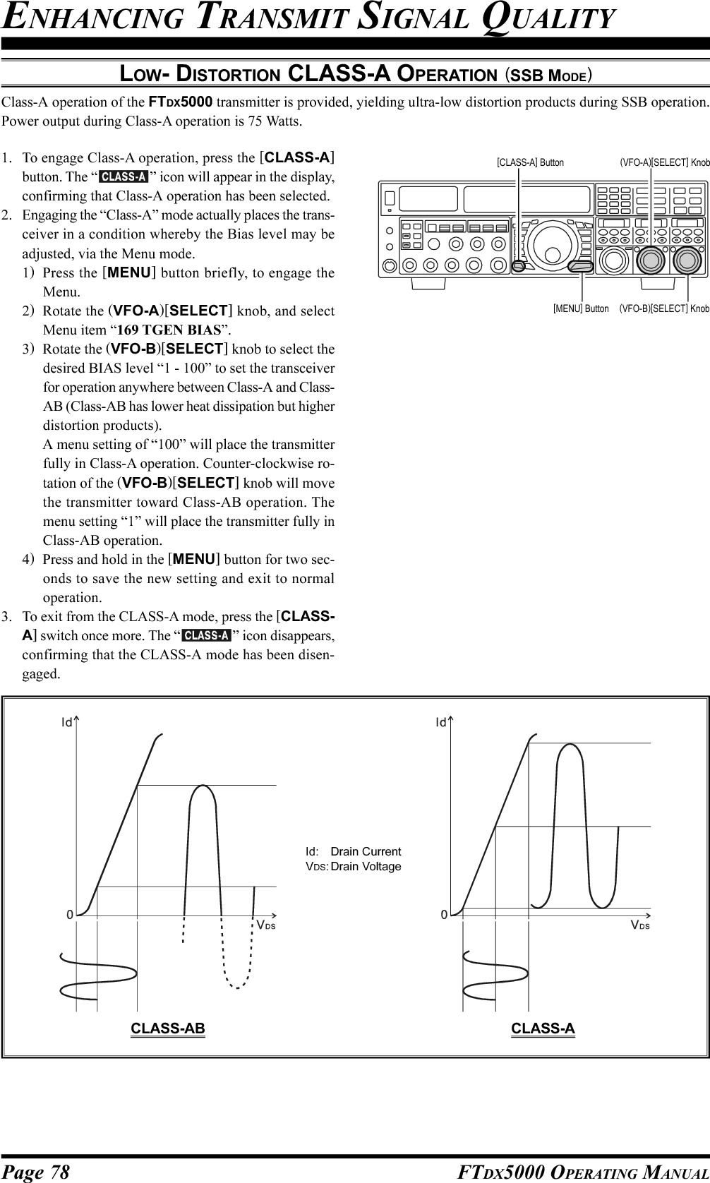
![Page 78 FTDX5000 OPERATING MANUALENHANCING TRANSMIT SIGNAL QUALITYLOW- DISTORTION CLASS-A OPERATION (SSB MODE)Class-A operation of the FTDX5000 transmitter is provided, yielding ultra-low distortion products during SSB operation.Power output during Class-A operation is 75 Watts.1. To engage Class-A operation, press the [CLASS-A]button. The “ ” icon will appear in the display,confirming that Class-A operation has been selected.2. Engaging the “Class-A” mode actually places the trans-ceiver in a condition whereby the Bias level may beadjusted, via the Menu mode.1)Press the [MENU] button briefly, to engage theMenu.2)Rotate the (VFO-A)[SELECT] knob, and selectMenu item “169 TGEN BIAS”.3)Rotate the (VFO-B)[SELECT] knob to select thedesired BIAS level “1 - 100” to set the transceiverfor operation anywhere between Class-A and Class-AB (Class-AB has lower heat dissipation but higherdistortion products).A menu setting of “100” will place the transmitterfully in Class-A operation. Counter-clockwise ro-tation of the (VFO-B)[SELECT] knob will movethe transmitter toward Class-AB operation. Themenu setting “1” will place the transmitter fully inClass-AB operation.4)Press and hold in the [MENU] button for two sec-onds to save the new setting and exit to normaloperation.3. To exit from the CLASS-A mode, press the [CLASS-A] switch once more. The “ ” icon disappears,confirming that the CLASS-A mode has been disen-gaged.CLASS-AB CLASS-AId: Drain CurrentVDS: Drain Voltage(VFO-B)[SELECT] Knob[MENU] Button(VFO-A)[SELECT] Knob[CLASS-A] Button](https://usermanual.wiki/Yaesu-Musen/20361X61.Users-Manual-2/User-Guide-1234777-Page-5.png)
![Page 80 FTDX5000 OPERATING MANUALChecking Your Recording1. Be sure that the front panel [MOX] and [VOX] but-tons are both “Off” (the LED imbedded in the buttonmust be off).2. Press the FH-2’s [1] ~ [5] key (whichever one you justrecorded in), and you will hear the contents of the voicememory you just recorded.ADVICE:You may adjust the playback level of the recording viaMenu item “020 DVS RX LVL”.Transmitting the Recorded Message1. Select the LSB, USB, AM, or FM mode using the frontpanel [MODE] buttons.2. Press the front panel [BK-IN] button briefly.3. Press the FH-2’s [1] ~ [5] key, depending on whichmemory register message you wish to transmit. If youhit the key again during playback, the message will beterminated.ADVICE:You may adjust the transmit (audio) level of the recordingvia Menu item “021 DVS TX LVL”.LOCKOFFONLOCKOFFONVOICE MEMORY (SSB/AM/FM MODES)You may utilize the Voice Memory capability of the FTDX5000 by plugging in the supplied FH-2 Remote Control Keypadinto the rear panel REMOTE jack.The Voice Memory system includes five memories capable of storing up to 20 seconds of voice audio each. The maximumthat any memory can hold is 20 seconds.Recording Your Own Voice in Memory1. Select the LSB, USB, AM, or FM mode using the frontpanel [MODE] buttons.2. Press the [MEM] key on the FH-2 briefly. A blinking“” icon will appear in the display3. Press any of the FH-2’s keys numbered [1] through[5] to select that memory storage register. If you donot press the PTT key (see next step) within five sec-onds, the memory storage process will be cancelled.4. Press the microphone’s PTT switch briefly, the“” icon will glow steadily, and recording willbegin.5. Speak into the microphone in a normal voice level torecord the message (such as “CQ DX, CQ DX, this isW 6 Delta X-Ray Charlie, W 6 Delta X-Ray Charlie,Over”). Remember that the time limit for recordingany message is 20 seconds.6. Press the FH-2’s [MEM] key to terminate the messagestorage process.TRANSMITTER CONVENIENCE FEATURESLOCKOFFONLOCKOFFON](https://usermanual.wiki/Yaesu-Musen/20361X61.Users-Manual-2/User-Guide-1234777-Page-7.png)
![Page 81FTDX5000 OPERATING MANUALVOX (AUTOMATIC TX/RX SWITCHING USING VOICE CONTROL: SSB/AM/FM MODES)Instead of using the microphone’s PTT switch or the front panel [MOX] switch to activate the transmitter, the VOX (VoiceOperated TX/RX Control) system provides hands-free, automatic activation of the transmitter, based on voice input intothe microphone. Setup of the VOX system takes only a few seconds.1. Adjust the [MIC] (gain) knob for SSB use, as describedon page 70.2. Set the [VOX] and [DELAY] knobs fully counter-clock-wise (to the left).3. Press the [VOX] button briefly, to engage VOX opera-tion. The [VOX] button will glow red.4. Speak into the microphone in a normal voice level,and rotate the [VOX] knob clockwise (to the right) untilthe point where your voice input activates the trans-mitter.ADVICE:Do not advance the setting of the [VOX] knob too far,as this will make the transmitter respond to minor back-ground noises in your station.5. Now stop speaking, and note the amount of time it takesfor the receiver to recover. If the hang time is too longor too short; rotate the [DELAY] knob, while speakingbriefly into the microphone, and then pausing, to setthe desired hang time. Clockwise rotation of the [DE-LAY] knob will increase the hang time.ADVICE:The hang time of the VOX circuit will show for 3 sec-onds in the lower right corner of the Main Displaywhenever the outer [DELAY] knob is turned.Alternately, the 3-second display feature may bechanged to show in the SUB DISPLAY-III windowvia Menu item “018 DISP INDI”. Additionally, youmay disable the 3-second display feature via Menu item“017 DISP LVL IND” See page 122 for details.MONITOR (SSB/AM/FM MODES)You may listen to the quality of your transmitted signal using the Monitor feature.1. Press the [MONI] button. The “ ” icon will ap-pear in the display, indicating that the Monitor is turnedon.2. During transmission, rotate the [MONI] knob to ad-just the audio level from the Monitor. Clockwise rota-tion of this knob will increase the volume level.3. To switch the Monitor off again, press the [MONI]button briefly once more. The “ ” icon will turnoff, confirming that the Monitor is now disengaged.TRANSMITTER CONVENIENCE FEATURES6. To exit from VOX operation, press the [VOX] buttononce more. We recommend doing this if you are goingto leave your station, to prevent inadvertent activationof the VOX system by a ringing nearby telephone,speaker audio from a TV, etc.ADVICE:The Anti-Trip setting sets the negative feedback of re-ceiver audio to the microphone, to prevent receiveraudio from activating the transmitter (via the micro-phone) can be adjusts via Menu item “175 TGENANTI VOX”.VOX operation may be engaged on voice modes (SSB/AM/FM) and on AFSK-based data modes. Use Menuitem “174 TGEN VOX SEL” (the selections are“MIC” and “DATA”).ADVICE:If you are using the speaker for monitoring, instead of headphones, excessive advancement of the [MONI] knob cancause feedback to occur. Additionally, this feedback can cause the VOX system to hang up in a loop, making it impos-sible to return to receive. Therefore, we recommend the use of headphones, if at all possible, or the minimum usablesetting of the [MONI] knob, if the speaker must be used.Because the monitor feature utilizes a sampling of the transmitter’s IF signal, it can be very useful for checking theadjustment of the Speech Processor or Parametric Equalizer on SSB, and for checking the general signal quality on AMand FM.[VOX] Button[VOX] Knob[DELAY] Knob[MIC] Knob[MONI] Button[MONI] Knob](https://usermanual.wiki/Yaesu-Musen/20361X61.Users-Manual-2/User-Guide-1234777-Page-8.png)
![Page 82 FTDX5000 OPERATING MANUALTRANSMITTER CONVENIENCE FEATURESSPLIT OPERATION USING THE TX CLARIFIER (VFO-A OPERATION)For split TX/RX operation in “casual” pile-ups, where the split is less than 10 kHz, the TX Clarifier (Offset Tuning) featuremay be utilized.1. Press the [TX CLAR/LOCK] button briefly. The“” and “ ” icon will appear in the display,and the programmed offset will beapplied to the receive frequency.ADVICE:If the “ ” and “ ” icon does not appear, checkto see if the LED imbedded in the [A/B] button glowsorange. If so, pressing the [A/B] button briefly, willcause the [A/B] button to go out. Now, press the [TXCLAR/LOCK] button briefly, to begin clarifier op-eration.2. Rotate the [CLAR(VFO-B)] knob to set the desiredtransmitter offset. A maximumsplit of ±9.999 kHz may be set.3. To exit from TX Clarifier operation, press the [TXCLAR/LOCK] button once more. The “ ” icon willdisappear from the display.QUICK POINT:When attempting to work a DX station on CW, in a split-frequency pile-up, remember that a large number of otherstations may also be using Yaesu transceivers with capa-bilities similar to your FTDX5000. On the DX side of thepile-up, everyone calling precisely on the same CW fre-quency will sound like a single tone! So you may havemore success if you use the RX Clarifier to find a hole inthe pile-up, instead of trying to zero-beat the last stationworked by the DX station.Clarifier Offset Bar IndicatorA visual depiction of the relative offset of the Clarifier may be displayed, using the Bar Indicator.1. Press the [MENU] button briefly, to enter the Menumode.2. Rotate the (VFO-A)[SELECT] knob to selectMenu item “012 DISP BAR SEL”.3. Rotate the (VFO-B)[SELECT] knob to select“CLAR (Clarifier)” (re-placing the default “CWTUNE (CW TUNING)”selection).4. Press and hold in the[MENU] button for twoseconds to save the newsetting and exit to nor-mal operation.ADVICE:The frequency step of the TX clarifier depends on theMain Tuning Dial knob.To listen to the pile-up calling the DX station, to findthe station currently being worked, you may press the[RX CLAR/FAST] button. Once you have zeroed inon the station calling the DX (use the SPOT functionon CW for precise alignment of your frequency), youmay then briefly press the [RX CLAR/FAST] buttonagain to cancel the RX Clarifier, and return to recep-tion on the DX station’s frequency.Just as with receiver clarifier operation, the amount ofoffset from the original VFO frequency will appear inthe small display window.As with receiver clarifier operation, when you turn theTX clarifier off the last-used offset is not lost, and willbe available if you turn the TX Clarifier back on. Toclear the Clarifier offset, briefly press the [CLEAR]button.[CLAR(VFO-B)] Knob[CLEAR] Button[TX CLAR/LOCK] Button[A/B] Button[Plus (+) Offset][Zero Offset](Minus (–) Offset)(VFO-B)[SELECT] Knob[MENU] Button(VFO-A)[SELECT] Knob](https://usermanual.wiki/Yaesu-Musen/20361X61.Users-Manual-2/User-Guide-1234777-Page-9.png)
![Page 83FTDX5000 OPERATING MANUALSPLIT-FREQUENCY OPERATIONA powerful capability of the FTDX5000 is its flexibility in Split Frequency operation, using the Main (VFO-A) and Sub(VFO-B) frequency registers. This makes the FTDX5000 especially useful for high-level DX-pedition use, as the Splitoperation capability is very advanced and easy to use.TRANSMITTER CONVENIENCE FEATURES1. Set the VFO-A frequency as desired.2. Set the VFO-B frequency.3. Now press the [SPLIT] button briefly. The front panelswitch/LEDs will look like this:(VFO-A)[RX] button: LED glows green(VFO-A)[TX] button: LED off(VFO-B)[RX] button: LED off(VFO-B)[TX] button: LED glows red3. During Split operation, the VFO-A register will be usedfor reception, while the VFO-B register will be usedfor transmission. If you press the [SPLIT] button oncemore, Split operation will be cancelled.(VFO-A)[RX] button: LED glows green(VFO-A)[TX] button: LED glows red(VFO-B)[RX] button: LED off(VFO-B)[TX] button: LED off4. You may also press the (VFO-A)[TX] button to returntransmit frequency control to the VFO-A side, therebycanceling split operation.ADVICE:During normal (non-split) VFO-A operation, you maysimply press the (VFO-B)[TX] button (located aboveand to the right of the [CLAR(VFO-B)] knob) to en-gage Split operation. The (VFO-B)[TX] button willglow red when you press the button.During Split operation, pressing the [AB] button willreverse the contents of VFO-A and VFO-B. Press the[AB] button once more, to return to the original fre-quency alignment.During Split operation, if you press the (VFO-B)[RX]button above and to the right of the [CLAR(VFO-B)]knob, you will engage Dual Receive operation. Nowyou can listen to both sides of the DX pile-up, andtransmit on the VFO-B frequency. This is very usefulto determine the timing of your calls, while also moni-toring both sides of the pile-up.During Split operation, you may also listen to the TXfrequency temporarily, by pressing the [TXW] button(just below the [SPLIT] button).It is possible to set different operating modes (for ex-ample, LSB and USB) on the two VFOs used duringSplit operation.During Split operation, it is also possible to set VFO-A and VFO-B to different amateur bands. But, remem-ber that Dual Reception must be within the same band.VFO Tracking FeatureIn the default setting, the VFO-A frequency and VFO-Bfrequency are changed individually using the Main Tun-ing Dial knob and the [CLAR(VFO-B)] knob.If you want to tune the VFO-A frequency and VFO-B fre-quency together, the VFO Tracking feature is very useful.Here is the procedure for activating the VFO Tracking fea-ture:1. Press the [MENU] button briefly, to engage the Menumode.2. Rotate the (VFO-A)[SELECT] knob to select Menuitem “038 GENE TRACK”.3. Rotate the (VFO-B)[SELECT] knob to select the de-sired Tracking mode.OFF: Disables the VFO Tracking feature.BAND: When you change the band on the VFO-A side,the VFO-B band will automatically change tobe the same band as VFO-A.FREQ: This function is similar to the “BAND” setting,and will additionally “lock” VFO-A and VFO-B together. Turning the Main Dial will tune bothVFO-A and VFO-B simultaneously.4. Press and hold in the [MENU] button for two secondsto lock in the new configuration and exit to normaloperation.(VFO-B)[SELECT] Knob[MENU] Button(VFO-A)[SELECT] Knob[CLAR(VFO-B)] Knob(VFO-B)[TX] Button(VFO-B)[RX] Button[SPLIT] Button[TXW] Button(VFO-A)[TX] Button(VFO-A)[RX] Button](https://usermanual.wiki/Yaesu-Musen/20361X61.Users-Manual-2/User-Guide-1234777-Page-10.png)
![Page 84 FTDX5000 OPERATING MANUALTRANSMITTER CONVENIENCE FEATURESSPLIT-FREQUENCY OPERATION1. Start with regular transceiver operation on the VFO-A.(VFO-A)[RX] button: LED glows green(VFO-A)[TX] button: LED glows red(VFO-B)[RX] button: LED off(VFO-B)[TX] button: LED off2. Press and hold in the [SPLIT] button for two sec-onds to engage the Quick Split feature, and apply afrequency 5 kHz above the VFO-A frequency tothe VFO-B frequency register.The VFO configuration will then be:(VFO-A)[RX] button: LED glows green(VFO-A)[TX] button: LED off(VFO-B)[RX] button: LED off(VFO-B)[TX] button: LED glows red3. Press and hold in the [SPLIT] switch for two sec-onds to increment the VFO-B frequency another+5 kHz.QUICK POINTS:The operating mode applied to the VFO-B registerwill be the same as that in use on the VFO-A regis-ter.The offset of the VFO-B from the VFO-A is pro-grammed via the Menu, and is set to +5 kHz at thefactory. Other offsets may be selected using the fol-lowing procedure:1. Press the [MENU] button briefly, to enter the Menumode.2. Rotate the (VFO-A)[SELECT] knob to selectMenu item “037 GENE Q SPLIT”.3. Rotate the (VFO-B)[SELECT] knob to select thedesired offset.The available selections are –20kHz ~ +20kHz (fac-tory default: +5 kHz).4. When you have completed all adjustments, pressand hold in the [MENU] button for two seconds tosave the new setting and exit to normal operation.If you only press the [MENU] button briefly to exit,any changes you performed will not be stored.Quick Split OperationThe Quick Split feature allows you to set a one-touch offset of +5 kHz, to be applied to the transmit frequency onVFO-B, as compared to the VFO-A frequency.[CLAR(VFO-B)] Knob(VFO-B)[TX] Button(VFO-B)[RX] Button[SPLIT] Button[TXW] Button(VFO-A)[TX] Button(VFO-A)[RX] Button(VFO-B)[SELECT] Knob[MENU] Button(VFO-A)[SELECT] Knob](https://usermanual.wiki/Yaesu-Musen/20361X61.Users-Manual-2/User-Guide-1234777-Page-11.png)

![Page 86 FTDX5000 OPERATING MANUALThe powerful CW operating capabilities of the FTDX5000 include operation using both an electronic keyer paddle and a“straight key” or emulation thereof, as is provided by a computer-based keying device.SETUP FOR STRAIGHT KEY (AND STRAIGHT KEY EMULATION) OPERATIONBefore starting, connect your key line(s) to the front and/or rear panel KEY jack(s). Be sure the [KEYER] button on thefront panel is turned off for now.CW MODE OPERATION1. Press the [CW] mode buttonto engage CW operation.The “ ” and “ ”icons will appear in the dis-play. The “ ” iconwill also appear in the dis-play; and the CW monitor isactivated.ADVICE:The operating modeis selected using the[MODE] button.The VFO, to whichthe selection is ap-plied, is selected by the [A] or [B] button (locatedto the upper left of the Main Tuning Dial knob).Usually, the [A] button glows red, signifying VFO-A is being adjusted. Alternately, pressing the [B]button will cause its indicator to glows orange, sig-nifying VFO-B adjustment. Therefore, press the [A]or [B] button to select the desired VFO, then pressthe [CW] button to select the CW mode.After initially selecting CW, if you press the [CW]button once more, you will engage the “CW Re-verse” mode (see page 92). Normally, the uppersideband (USB) is used in conjunction with CW.In reverse CW the lower sideband (LSB) is used.2. Rotate the Main Tuning Dial knob to select the desiredoperating frequency.3. Press the [BK-IN] buttonbriefly, to engage automaticactivation of the transmitterwhen you close the CW key.The “ ” icon will appearin the display.ADVICE:When you close your CWkey, the transmitter will automatically be activated,and the CW carrier will be transmitted. When yourelease the key, transmission will cease after a briefdelay; the delay time is user-programmable, per thediscussion on page 93.As shipped from the factory, the FTDX5000 TX/RX system for CW is configured for “Semi-break-in” operation. However, using Menu item “063 A1ABK-IN”, you may change this setup for full break-in (QSK) operation, whereby the switching is quickenough to hear incoming signals in the spaces be-tween the dots and dashes of your transmission. Thismay prove very useful during contest and traffic-handling operations.4. Operation using your CW key may now proceed.A CW sidetone sounds from a speakerin accordance with your keying. Ad-just the [MONI] knob for a comfort-able listening level of the CWsidetone.Main Tuning Dial knob[BK-IN] Button[B] Button[MONI] Button[MODE] Buttons[A] Button[RF PWR] Knob [MONI] Knob](https://usermanual.wiki/Yaesu-Musen/20361X61.Users-Manual-2/User-Guide-1234777-Page-13.png)
![Page 87FTDX5000 OPERATING MANUALADVICE:You may disable the CW sidetone by pressing the[MONI] button. The “ ” icon will turn off, con-firming that the Monitor is now disengaged.If you set the [BK-IN] button to off, you may practiceyour sending without having the signal go out over theair (sidetone only).If you reduce power using the [RF PWR] knob, theALC meter reading will increase. This is normal anddoes not indicate any problem whatsoever (because in-creased ALC voltage is being used to lower the power).SETUP FOR STRAIGHT KEY (AND STRAIGHT KEY EMULATION) OPERATIONTERMINOLOGY:Semi-break-inThis is a pseudo- “VOX” mode used on CW, wherethe closure of the CW key will engage the transmitter.Releasing the key, will allow the receiver to recoverafter a short delay. No signals will be heard betweenthe spaces between dots and dashes (unless the send-ing speed is extremely slow).Full break-inFull break-in (Also known as “Full QSK”) involvesvery fast switching between transmit and receive, suchthat incoming signals may be heard between the dotsand dashes as you send them. This allows you to hear astation that suddenly starts transmitting on your fre-quency, while you are in the midst of sending a mes-sage.](https://usermanual.wiki/Yaesu-Musen/20361X61.Users-Manual-2/User-Guide-1234777-Page-14.png)
![Page 88 FTDX5000 OPERATING MANUALUSING THE BUILT-IN ELECTRONIC KEYERConnect the cable from your keyer paddle to the front or rear panel KEY jack.1. Press the [CW] mode buttonto engage CW operation.The “ ” and “ ”icons will appear in the dis-play, and the CW monitorwill be activated.ADVICE:The operating modeis selected using the[MODE] button.The (A or B) VFO towhich the selectionis applied, is se-lected by the [A] or[B] button, located to the upper left of the MainTuning Dial knob. Usually, the [A] button glowsred, signifying VFO-A is being adjusted. Alter-nately, pressing the [B] button will cause its indi-cator to glow orange, signifying VFO-B adjustment.Therefore, press the [A] or [B] button to select thedesired VFO, then press the [CW] button to selectthe CW mode.After initially selecting CW, If you press the [CW]button once more you will engage the “CW Re-verse” mode (see page 92), whereby the “oppo-site” sideband injection is used. Normally, the up-per sideband (USB) is used in conjunction with CW.In reverse CW the lower sideband (LSB) is used.The “ ” and “ ” icons will appear if youselect CW Reverse.2. Rotate the Main Tuning Dial knob to select the desiredoperating frequency.3. Press the [KEYER] button.The “ ” icon will ap-pear in the display, confirm-ing that the built-in Elec-tronic Keyer is now active.4. Rotate the [SPEED] knob toset the desired sending speed(4 ~ 60 wpm). Clockwise ro-tation of the [SPEED] knob will in-crease the keying speed.ADVICE:The keying speed will show for 3seconds in the lower right corner of the Main Dis-play whenever the outer [SPEED] knob is turned.Alternately, the 3-second display feature may bechanged to show in the SUB DISPLAY-III win-dow via Menu item “018 DISP INDI”. Addition-ally, you may disable the 3-second display featurevia Menu item “017 DISP LVL IND” See page122 for details.When you press either the “Dot” or “Dash” side ofyour paddle, the transmitter will automatically beactivated.5. If you press the [BK-IN] button briefly, “semi-break-in” operation (discussed previously) will be engaged.6. CW operation utilizing your paddle may now com-mence.A CW sidetone sounds from a speakerin accordance with your keying. Ad-just the [MONI] knob for a comfort-able listening level of the CWsidetone.Main Tuning Dial knob[BK-IN] Button[B] Button[MONI] Button[MODE] Buttons[MONI] Knob[A] Button[RF PWR] Knob[KEYER] Button[SPEED] KnobCW MODE OPERATION](https://usermanual.wiki/Yaesu-Musen/20361X61.Users-Manual-2/User-Guide-1234777-Page-15.png)
![Page 89FTDX5000 OPERATING MANUALADVICE:You may disable the CW sidetone by pressing the[MONI] button. The “ ” icon will turn off, con-firming that the Monitor is now disengaged.When you utilize your keyer paddle, the transmitterwill automatically be activated, and the CW charac-ters (or a string of dots and dashes) will be transmit-ted. When you release the keyer paddle contacts, trans-mission will cease after a brief delay. The delay time isuser-programmable, per the discussion on page 93.If you reduce power using the [RF PWR] knob, theALC meter reading will increase. This is normal anddoes not indicate any problem whatsoever (because in-creased ALC voltage is being used to lower the power).USING THE BUILT-IN ELECTRONIC KEYERCW MODE OPERATIONFull Break-in (QSK) OperationAs shipped from the factory, the FTDX5000 TX/RX sys-tem for CW is configured for “Semi-break-in” operation.However, using Menu item “063 A1A BK-IN”, you maychange this setup for full break-in (QSK) operation,whereby the switching is quick enough to hear incomingsignals in the spaces between the dots and dashes of yourtransmission.1. Press the [MENU] button to enter the Menu mode.2. Rotate the (VFO-A)[SELECT] knob to select Menuitem “063 A1A BK-IN”.3. Rotate the (VFO-B)[SELECT] knob to set this Menuitem to “FULL”.4. Press and hold in the [MENU] button for two secondsto save the new setting and exit.(VFO-B)[SELECT] Knob[MENU] Button(VFO-A)[SELECT] Knob](https://usermanual.wiki/Yaesu-Musen/20361X61.Users-Manual-2/User-Guide-1234777-Page-16.png)
![Page 90 FTDX5000 OPERATING MANUALA number of interesting and useful features are available during Electronic Keyer operation.SETTING THE KEYER WEIGHT (DOT/SPACE:DASH) RATIOThe Menu may be used to adjust the Weight for the built-in Electronic Keyer. The default weighting is 3:1 (a dash isthree times longer than a dot or space).USING THE BUILT-IN ELECTRONIC KEYERCW MODE OPERATION1. Press the [MENU] button briefly, to enter the Menumode.2. Rotate the (VFO-A)[SELECT] knob to selectMenu item “065 A1A WEIGHT”.3. Rotate the (VFO-B)[SELECT] knob to set theweight to the desired value. The available adjust-ment range is for a Dot/Space:Dash ratio of “2.5”~ “4.5” (default value: “3.0”).4. When you are finished, press and hold in the[MENU] button for two seconds to save the newsetting and exit to normal operation.SELECTING THE KEYER OPERATING MODEThe configuration of the Electronic Keyer may be customized independently for the front and rear KEY jacks of theFTDX5000. This permits utilization of Automatic Character Spacing (ACS), if desired, as well as the use of theelectronic keyer via the front jack and a straight key or computer-driven keying line via the rear panel.1. Press the [MENU] button briefly, to enter the Menumode.2. Rotate the (VFO-A)[SELECT] knob to selectMenu item “057 A1A F-TYPE” (for the front KEYjack) or “059 A1A R-TYPE” (for the rear-panelKEY jack).3. Rotate the (VFO-B)[SELECT] knob to set thekeyer to the desired mode. The available selectionsare:OFF: The built-in Electronic Keyer is turned off(“straight key” mode).BUG: Dots will be generated automatically bythe keyer, but dashes must be sent manu-ally.ELEKEY: Both dots and dashes will be generatedautomatically when you use your paddle.ACS: Same as “ELEKEY” except that the spac-ing between characters is precisely set bythe keyer to be the same length as a dash(three dots in length)4. When you are finished, press and hold in the[MENU] button for two seconds to save the newsetting and exit to normal operation.Inter-characterspacing to shortMorse“E” & “T”Morse“E” & “T”ACS “ON”ACS “OFF”(VFO-B)[SELECT] Knob[MENU] Button(VFO-A)[SELECT] Knob(VFO-B)[SELECT] Knob[MENU] Button(VFO-A)[SELECT] Knob](https://usermanual.wiki/Yaesu-Musen/20361X61.Users-Manual-2/User-Guide-1234777-Page-17.png)
![Page 91FTDX5000 OPERATING MANUALCW CONVENIENCE FEATURESCW SPOTTING (ZERO-BEATING)“Spotting” (zeroing in on another CW station) is a handy technique for ensuring that you and the other station are preciselyon the same frequency.For everyday operation, the (CW) [PITCH] knob allows you to set the center of the receiver passband, as well as the offsetpitch of your CW carrier signal, to the tone pitch you prefer to listen to.The Tuning Offset Indicator in the display may also be moved so you can adjust your receiver frequency to center theincoming station on the pitch corresponding to that of your transmitted signal.Using the SPOT SystemWhile pressing the front panel [SPOT] button, the spottone will be heard in the speaker, and the spot tone fre-quency will show in the lower right corner of the MainDisplay. This tone corresponds to the pitch of your trans-mitted signal, and if you adjust the receiver frequency tomatch the pitch of the received CW signal to that of thespot tone, your transmitted signal will be precisely matchedto that of the other station.Release the [SPOT] button to turn the spot tone off.ADVICE:In a tough DX pile-up, you may actually want to usethe SPOT system to find a “gap” in the spread of call-ing stations, instead of zeroing in precisely on the laststation being worked by the DX station. From the DXside, if a dozen or more operators (also using Yaesu’sSPOT system) all call precisely on the same frequency,their dots and dashes merge into a single, long tonethat the DX station cannot decipher. In such situations,calling slightly higher or lower may get your callthrough.The Tuning Offset Indicator in the display may be uti-lized for CW frequency adjustment, as well. Its con-figuration is set via Menu item “012 DISP BAR SEL”at the factory, and the Tuning Offset Indicator is al-ready set to the “CW TUNE” selection.QUICK POINTS:The CW spotting process utilizes the spot tone or theTuning Offset Indicator, with the actual offset pitchbeing set by the [PITCH] knob on the front panel. Theoffset pitch may be set to any frequency between 300Hz and 1050 Hz, in 50 Hz steps, and you can eithermatch tones audibly (using the [SPOT] button) or alignthe receiver frequency so that the central red bar onthe Tuning Offset Indicator lights up. Note that thereare 21 “dots” on the Tuning Offset Indicator, and de-pending on the resolution selected, the incoming CWsignal may fall outside the visible range of the bar in-dicator, if you are not reasonably close to the properalignment of tones.The displayed frequency on CW, normally reflects the“zero beat” frequency of your offset carrier. That is, ifyou were to listen on USB on 14.100.70 MHz to asignal with a 700 Hz offset, the “zero beat” frequencyof that CW carrier would be 14.000.70 MHz. The lat-ter frequency is what the FTDX5000 displays, by de-fault. However, you can change the display to be iden-tical to what you would see on SSB by using Menuitem “066 A1A FRQ DISP” and setting it to “FREQ”instead of its default “PITCH” setting.[SPOT] Button[PICTH] KnobRetune:Shift to Higher Frequency: When the CW reversefeature is activated, the indica-tor of the Tuning Offset Indicator will also be reversed.Zero-InRetune:Shift to Lower Frequency](https://usermanual.wiki/Yaesu-Musen/20361X61.Users-Manual-2/User-Guide-1234777-Page-18.png)
![Page 92 FTDX5000 OPERATING MANUALUSING CW REVERSEIf you experience a difficult interference situation, where an interfering station cannot readily be eliminated, you may wishto try receiving using the opposite sideband. This may move the interfering station’s frequency in a direction that may lenditself more readily to rejection.1. To start, let’s use a typical example where you have setthe CW mode (using the default “USB” injection) onthe VFO-A receiver.2. Now be sure your mode selection is still set for theVFO-A register, and press the [CW] mode button oncemore. The “ ” and “ ” icons will appear in thedisplay, indicating that the “LSB” injection side hasnow been selected.3. When using Dual Receive, press the [B] button, whichis located to the upper left of the Main Tuning Dialknob. Then press the [CW] button to engage CW Re-verse on the VFO-B receiver, in exactly the same wayas for the VFO-A receiver.4. Press the [CW] mode button once more to return tothe normal (USB) injection side and cancel CW Re-verse operation (the “ ” and “ ” icons willappear in the display).NOTES:When CW Reverse is engaged, the Tuning Offset In-dicator action will concurrently be reversed.When the incoming signal pitch tone is properlyaligned, the central red marker lights up whether ornot CW Reverse is engaged.CW CONVENIENCE FEATURESIn the illustration, Figure “A” demonstrates the nor-mal CW injection setup, using the USB side. InFigure “B”, CW Reverse has been engaged. LSB-side injection is being used to eliminate interfer-ence.The beneficial effect of switching sidebands canbe clearly seen in this example.RX PassbandRX PassbandCarrierCarrierQRMQRMNormal CW( )CW Reverse( )USBLSBAB[CW] Button[PICTH] Knob[A], [B] ButtonAUDIO PEAK FILTER1. Where you have set the CW mode on the VFO-A re-ceiver, press the (VFO-A)[CONT/APF] button briefly,to activate the APF (Audio Peak Filter) which providesa very narrow audio bandwidth. The peak position ofthe APF will appear in the SUB DISPLAY-II win-dow, and the (VFO-A)[SELECT] knob will now func-tion as the APF knob.2. Rotate the (VFO-A)[SELECT] knob to the left or rightto reduce any interference.3. To disable the APF, press the (VFO-A)[CONT/APF]button briefly, again.4. To activate the APF (Audio Peak Filter) on VFO-B,press the (VFO-B)[CONT/APF] button briefly, andadjust the (VFO-B)[SELECT] knob to reduce any in-terference. The peak position of the APF will be indi-cated in the SUB DISPLAY-III window.(VFO-B)[SELECT] Knob(VFO-A)[CONT/APF] Button(VFO-B)[CONT/APF] Button(VFO-A)[SELECT] KnobRetune:Shift to Lower FrequencyZero-InRetune:Shift to Higher Frequency](https://usermanual.wiki/Yaesu-Musen/20361X61.Users-Manual-2/User-Guide-1234777-Page-19.png)
![Page 93FTDX5000 OPERATING MANUALCW DELAY TIME SETTINGDuring semi-break-in (not QSK) operation, the hang time of the transmitter, after you have finished sending, may beadjusted to a comfortable value consistent with your sending speed. This is the functional equivalent to the “VOX Delay”adjustment used on voice modes, and the delay may be varied anywhere between 20 milli-seconds with the ([DELAY]knob set fully counter-clockwise) and 5 seconds (fully clockwise).1. Press the [BK-IN] button to enable CW transmission(Menu item “059 A1A BK-IN” must be set to “SEMI”).2. Start sending, and adjust the [DELAY] knob so thatthe hang time is as you prefer for comfortable opera-tion.ADVICE:The delay time will show for 3 seconds in the lowerright corner of the Main Display whenever the outer[DELAY] knob is turned.Alternately, the 3-second display feature may bechanged to show in the SUB DISPLAY-III windowvia Menu item “018 DISP INDI”. Additionally, youmay disable the 3-second display feature via Menu item“017 DISP LVL IND” See page 122 for details.[BK-IN] Button[DELAY] KnobCW PITCH ADJUSTMENTRotation of the front panel’s [PITCH] knob will allowadjustment of the center frequency of the receiver pass-band, as well as the pitch of your offset CW carrier, to thetone you prefer. The tone may be varied between 300 Hzand 1050 Hz, in 50 Hz steps.ADVICE:The spot tone frequency will show for 3 seconds in thelower right corner of the Main Display whenever the outer[PROC] knob is turned.Alternately, the 3-second display feature may be changedto show in the SUB DISPLAY-III window via Menu item“018 DISP INDI”. Additionally, you may disable the 3-second display feature via Menu item “017 DISP LVLIND” See page 122 for details.TERMINOLOGY:CW Pitch: If you tuned to an exact “zero beat” on anincoming CW signal, you could not copy it (“Zero beat”implies a 0 Hz tone). Therefore, the receiver is offset sev-eral hundred Hz (typically), to produce an audio tone yourear can detect. The BFO offset associated with this tuning(that produces the comfortable audio tone) is called theCW Pitch.[PICTH] KnobCW CONVENIENCE FEATURES](https://usermanual.wiki/Yaesu-Musen/20361X61.Users-Manual-2/User-Guide-1234777-Page-20.png)
![Page 94 FTDX5000 OPERATING MANUALMESSAGE MEMORY PROGRAMMING (USING YOUR PADDLE)1. Set the operating mode to CW.2. Set the [BK-IN] button to Off.3. Turn the internal Electronic Keyer “on” by pressingthe [KEYER] button briefly, if necessary.4. Press the FH-2’s [MEM] key.5. Press the [1] ~ [5] key on the FH-2 tobegin the memory storage process.6. Send the desired message using your keyer paddle.7. Press the [MEM] key on the FH-2 oncemore at the end of your message. Up to50 characters may be stored among thefive memories.CONTEST MEMORY KEYERThe FTDX5000 in capable of the automatic sending of CW messages (as you might do in a contest) by plugging thesupplied FH-2 Remote Control Keypad into the rear panel REMOTE jack. Two techniques for message storage are avail-able: you may either send the desired message contents using your keyer paddle (“Message Memory”), or you may inputthe text characters using the (VFO-A)[SELECT] knob and (VFO-B)[SELECT] knobs (“Text Memory”).MESSAGE MemoryFive memory channels capable of retaining 50 characters total are provided (using the PARIS standard for character andword length).Example: CQ CQ CQ DE W6DXC K (19 characters)-- •-- •-- -- •-- -- •-- •-- -- •-- -- •-- •-- -- •-- -- •• • •-- -- -- •••• -- •• -- ••-- -- •-- •-- •--(C)(Q)(C)(Q)(C)(Q)(D)(E)(W)(6)(D)(X)(C)(K)CW CONVENIENCE FEATURESSTORING A MESSAGE INTO MEMORY1. Press the [MENU] button briefly, to enter the Menumode.2. Rotate the (VFO-A)[SELECT] knob to select the CWMemory Register you wish to store the message into.For now we are just selecting the message entry tech-nique (Keyer entry).025 KEY CW MEM1026 KEY CW MEM2027 KEY CW MEM3028 KEY CW MEM4029 KEY CW MEM53. Rotate the (VFO-B)[SELECT] knob to set the selectedMemory Register to “MESSAGE”. If you want to useyour keyer paddle for message entry on all memories,set all five Menu items (#025 ~ 029) to “MESSAGE”.4. Press and hold in the [MENU] button for two secondsto save the new settings and exit.TERMINOLOGY:PARIS Word Length: By convention in the Amateurindustry (utilized by ARRL and others), the length of one“word” of CW is defined as the length of the Morse Codecharacters spelling the word “PARIS.” This character (dot/dash/space) length is used for the rigorous definition ofcode speed in “words per minute.”(VFO-B)[SELECT] Knob[MENU] Button(VFO-A)[SELECT] KnobLOCKOFFONLOCKOFFONLOCKOFFONNOTE:You must exercise care in sending to ensure that thespaces between letters and words are accurately done.If your timing is off, the spacing may not come outright in the stored message.For ease in setting up the keyer memories, we recom-mend you set Menu item “057 A1A F-TYPE” and/or“059 A1A R-TYPE” to “ACS” (Automatic CharacterSpacing) while you are programming the keyer memo-ries.](https://usermanual.wiki/Yaesu-Musen/20361X61.Users-Manual-2/User-Guide-1234777-Page-21.png)
![Page 95FTDX5000 OPERATING MANUALCW CONVENIENCE FEATURESCONTEST MEMORY KEYERCHECKING THE CW MEMORY CONTENTS1. Be sure that Break-in is still turned “off” by the [BK-IN] button.2. Press the [MONI] button to enable the CW monitor.3. Press the FH-2’s [1] ~ [5] key to checkyour work. You will hear the results inthe sidetone, but no RF energy will betransmitted.Transmitting in the Beacon ModeIt is possible to automatically transmit a “Beacon” message repetitively. The message may be input either with thekeyer paddle, or programmed using the MENU “TEXT” input method. The time delay between message repeatsmay be set anywhere between 1 ~ 255 seconds via Menu item “022 KEY BEACON”. If you do not wish the“Beacon” message to repeat, then, set this Menu item to “OFF”. Press a [1] ~ [5] key on the FH-2 Remote ControlKeypad, to select the register into which the Beacon message was stored. Repetitive transmissions of the Beaconmessage will begin. Press one of these keys once more to halt the Beacon transmissions.NOTE:Adjust the monitor level using the [MONI] knob.ON-THE-AIR CW MESSAGE PLAYBACK1. Press the [BK-IN] button to enable transmission. Ei-ther Full- or Semi-break-in will be engaged, depend-ing on the setting of Menu item “063 A1A BK-IN”.2. Press an FH-2’s [1] ~ [5] key to trans-mit the programmed message.LOCKOFFONNOTE:If you subsequently decide to use the “Text Memory” tech-nique for message storage, on a particular memory regis-ter, the contents of a message stored using the keyer paddleinput will not be transferred over when the Menu ModeSetting is changed to “TEXT”).LOCKOFFON](https://usermanual.wiki/Yaesu-Musen/20361X61.Users-Manual-2/User-Guide-1234777-Page-22.png)
![Page 96 FTDX5000 OPERATING MANUALTEXT MemoryThe four channels of CW message memory (up to 50 characters total) may also be programmed using the text-entrytechnique. This is somewhat slower than sending the message directly from your keyer paddle, but accuracy of characterspacing is ensured. Example 1: CQ CQ CQ DE W6DXC K} (20 characters)You may also utilize another powerful feature of the CW Memory Keyer, the sequential Contest Number (“Countup”)feature. Example 2: 599 10 200 # K} (15 characters)CONTEST MEMORY KEYERSTORING TEXT INTO MEMORY1. Press the [MENU] button briefly, to enter the Menumode.2. Rotate the (VFO-A)[SELECT] knob to select the CWMemory Register you wish to store the message in.For now, you are just selecting the message entry tech-nique (Text entry).025 KEY CW MEM1026 KEY CW MEM2027 KEY CW MEM3028 KEY CW MEM4029 KEY CW MEM53. Rotate the (VFO-B)[SELECT] knob to set the selectedMemory Register to “TEXT”. If you want to use theText method for message entry on all memories, set allfive Menu items (#025 ~ 029) to “TEXT”.4. Press and hold in the [MENU] button for two secondsto save the new settings and exit.CW CONVENIENCE FEATURESTEXT MESSAGE PROGRAMMING1. Set the operating mode to CW.2. Set the [BK-IN] button to “off”.3. Turn the internal Electronic Keyer “on” by brieflypressing the [KEYER] button.4. Press the FH-2’s [MEM] key.5. Press the [1] ~ [5] key on the FH-2 tobegin the memory storage process.6. Use the FH-2’s [] and [] keys toset the cursor position and use the []and [] keys to choose the letter/num-ber to be programmed in each slot ofthe memory. In the case of the secondexample above, the “#” character des-ignates the slot where the Contest Num-ber will appear.ADVICE:You may set the cursor position with the (VFO-A)[SELECT] knob, and then choose the letter/num-ber with the (VFO-B)[SELECT] knob.LOCKOFFONLOCKOFFONLOCKOFFONCursorCurrent Cursor PositionCW Memory Register Number MessageSelect the cursor position Choose the letter/number(VFO-B)[SELECT] Knob[MENU] Button(VFO-A)[SELECT] Knob](https://usermanual.wiki/Yaesu-Musen/20361X61.Users-Manual-2/User-Guide-1234777-Page-23.png)
![Page 97FTDX5000 OPERATING MANUALCONTEST MEMORY KEYER7. When the message is complete, add the “}” characterat the end to signify the termination of the message.8. Press and hold in the FH-2 [MEM] keyfor 2 seconds to exit, once all charac-ters (including “}”) have been pro-grammed.CHECKING THE CW MEMORY CONTENTS1. Be sure that Break-in is still turned “off” by the [BK-IN] button.2. Press the [MONI] button briefly, to enable the CWmonitor.3. Press an FH-2 [1] ~ [5] key to checkyour work. You will hear the storedmessage with the CW monitor sidetone,but no RF energy will be transmitted.NOTE:Adjust the monitor level using the [MONI] knob.ON-THE-AIR CW MESSAGE PLAYBACK1. Press the [BK-IN] button briefly to enable transmis-sion. Either Full- or Semi-break-in will be engaged de-pending on the setting of Menu item “063 A1A BK-IN.”2. Press the FH-2’s [1] ~ [5] key to trans-mit the programmed message.NOTE:If you subsequently decide to use the “Message Memory”technique for message storage, on a particular memoryregister, the contents of the message stored using text in-put will not be transferred over when you select the “Mes-sage Memory” technique (the Menu Mode Setting is setto “MESSAGE”).Contest Number ProgrammingUse this process if you are starting a contest, or ifyou somehow get out of sync with the proper num-ber in the middle of a contest.1. Press the [MENU] button briefly, to enter theMenu mode.2. Rotate the (VFO-A)[SELECT] knob to selectMenu item “024 KEY CONTEST”.3. Rotate the (VFO-B)[SELECT] knob to set theContest Number to the desired value.ADVICE:Press the [CLEAR] button briefly (locatedabove the [CLAR(VFO-B)] knob), to reset theContest Number to “1”.4. Press and hold in the [MENU] button for twoseconds to store the new number and exit tonormal operation.CW CONVENIENCE FEATURESLOCKOFFONLOCKOFFONLOCKOFFONLOCKOFFONDecrementing the Contest NumberUse this process if the current contest number getsahead of the actual number you want to send (incase of a duplicate QSO, for example).Press the FH-2 control’s [DEC] key.The current Contest Number will bereduced by one. Press the [DEC]button briefly, as many times as nec-essary, to reach the desired number.If you go too far, use the “ContestNumber Programming” techniquedesireded at the left.TEXT!“””#$%&‘’’CW CODESNAF---SXKAASWGTEXT(“)”*+,---.CW CODEKNKK---ARMIMDUAAATEXT/“:”;<=>?CW CODEDNOSKR---BT---IMITEXT@“[”\]^_‘}’CW CODE@---AL------IQ---](https://usermanual.wiki/Yaesu-Musen/20361X61.Users-Manual-2/User-Guide-1234777-Page-24.png)
![Page 98 FTDX5000 OPERATING MANUALFM MODE OPERATIONBASIC OPERATION1. To select the FM operatingmode, press the [AM/FM]button several times, untilthe “ ” icon appears inthe display, .ADVICE:The operating mode isselected using the[MODE] button,and then pressing the[A] or [B] button(located to the upperleft of the Main Tun-ing Dial knob), tochoose VFO-A or VFO-B, to which the selection isapplied. Usually, the [A] button glows red, signify-ing VFO-A is being adjusted. Similarly, pressingthe [B] button will cause its indicator to glow or-ange, signifying VFO-B adjustment. Therefore,press the [A] or [B] button to select the desiredVFO, then press the [AM/FM] button to select theFM mode.2. Rotate the Main Tuning Dial knob (in the case of VFO-A operation) to tune the desired operating frequency.Pressing the microphone [UP] or [DWN] button willcause the frequency to change in 5 kHz steps.3. Press the microphone PTT switch (or press the frontpanel [MOX] button) to transmit. Speak into the mi-crophone in a normal voice level. Release the PTT or[MOX] switch to return to receive.Main Tuning Dial knob[METER] Switch [B] Button[MOX] Button[MODE] Buttons[MIC] Knob[RF PWR] Knob[A] Button4. There are two methods of adjusting the microphonegain for FM operation. At the factory, a default levelhas been programmed that should be satisfactory formost situations. However, using Menu item “079 F3EMICGAIN”, you may set a different fixed value, oryou may choose the “MCVR” option which then letsyou use the front panel [MIC] knob to set the micro-phone gain in the FM mode.ADVICE:The Transmit Monitor is another helpful way of veri-fying proper adjustment of the FM MIC Gain. By press-ing the [MONI] button, and then adjusting the [MONI]knob for a comfortable listening level while you aretransmitting, you will be able to hear the difference indeviation as you make adjustments.FM is only used in the 28 MHz and 50 MHz Amateurbands covered in the FTDX5000. Please do not useFM on any other bands.](https://usermanual.wiki/Yaesu-Musen/20361X61.Users-Manual-2/User-Guide-1234777-Page-25.png)
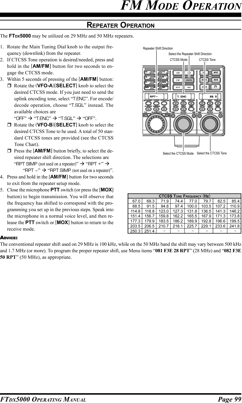
![Page 99FTDX5000 OPERATING MANUALFM MODE OPERATIONREPEATER OPERATIONCTCSS TONE FREQUENCY (Hz)67.0 69.3 71.9 74.4 77.0 79.7 82.5 85.488.5 91.5 94.8 97.4 100.0 103.5 107.2 110.9114.8 118.8 123.0 127.3 131.8 136.5 141.3 146.2151.4 156.7 159.8 162.2 165.5 167.9 171.3 173.8177.3 179.9 183.5 186.2 189.9 192.8 196.6 199.5203.5 206.5 210.7 218.1 225.7 229.1 233.6 241.8250.3 251.4ADVICE:The conventional repeater shift used on 29 MHz is 100 kHz, while on the 50 MHz band the shift may vary between 500 kHzand 1.7 MHz (or more). To program the proper repeater shift, use Menu items “081 F3E 28 RPT” (28 MHz) and “082 F3E50 RPT” (50 MHz), as appropriate.The FTDX5000 may be utilized on 29 MHz and 50 MHz repeaters.1. Rotate the Main Tuning Dial knob to the output fre-quency (downlink) from the repeater.2. If CTCSS Tone operation is desired/needed, press andhold in the [AM/FM] button for two seconds to en-gage the CTCSS mode.3. Within 5 seconds of pressing of the [AM/FM] button:Rotate the (VFO-A)[SELECT] knob to select thedesired CTCSS mode. If you just need to send theuplink encoding tone, select “T.ENC”. For encode/decode operation, choose “T.SQL” instead. Theavailable choices are“OFF” “T.ENC” “T.SQL” “OFF”.Rotate the (VFO-B)[SELECT] knob to select thedesired CTCSS Tone to be used. A total of 50 stan-dard CTCSS tones are provided (see the CTCSSTone Chart).Press the [AM/FM] button briefly, to select the de-sired repeater shift direction. The selections are“RPT SIMP (not used on a repeater)” “RPT +” “RPT –” “RPT SIMP (not used on a repeater)”.4. Press and hold in the [AM/FM] button for two secondsto exit from the repeater setup mode.5. Close the microphone PTT switch (or press the [MOX]button) to begin transmission. You will observe thatthe frequency has shifted to correspond with the pro-gramming you set up in the previous steps. Speak intothe microphone in a normal voice level, and then re-lease the PTT switch or [MOX] button to return to thereceive mode.CTCSS ToneSelect the Repeater Shift DirectionRepeater Shift DirectionSelect the CTCSS Mode Select the CTCSS ToneCTCSS Mode](https://usermanual.wiki/Yaesu-Musen/20361X61.Users-Manual-2/User-Guide-1234777-Page-26.png)
![Page 101FTDX5000 OPERATING MANUALMEMORY OPERATIONQMB (QUICK MEMORY BANK)The Quick Memory Bank consists of five memories (labeled “C-1” through “C-5.”) independent from the regular and PMSmemories. These can quickly store operating parameters for later recall.QMB Channel Storage1. Tune to the desired frequency on VFO-A.2. Press the blue [STO] button briefly. The“beep” will confirm that the contents ofVFO-A have been written to the currentlyavailable QMB memory.3 If you repeatedly press the [STO] button, the QMBmemories will be written in the following order:C-2 C-3 C-4 C-5 C-1 ......Once all five QMB memories have data in them, previousdata (starting with channel “C-1”) will be over-written, ona first-in, first-out basis.QMB Channel Recall1. Press the blue [RCL] button briefly. Thecurrent QMB channel data will be shownon the VFO-A frequency display field,and the QMB memory channel num-ber will appear in the small window atthe lower right corner of the display.2. Repeatedly pressing the [RCL] button will rotatethrough the QMB channels:C-2 C-3 C-4 C-5 C-1 ......3. Press the [V/M] button briefly, to return to the VFO orMemory mode.ADVICE:Rotating the Main Tuning Dial knob, or changing the op-erating mode will place the transceiver in the “MemoryTune” mode. This is a temporary “pseudo-VFO” methodof tuning off of a stored memory channel. If you do notover-write the contents of the current memory channel,the original contents will not be disturbed by the initiationof Memory Tune operation.[STO] Button[RCL] Button[V/M] Button](https://usermanual.wiki/Yaesu-Musen/20361X61.Users-Manual-2/User-Guide-1234777-Page-28.png)
![Page 102 FTDX5000 OPERATING MANUALMEMORY OPERATIONREGULAR MEMORY OPERATIONThe Regular Memory of the FTDX5000 allows storage and recall of up to 99 memories, each storing frequency, mode, anda wide variety of status information detailed previously. Memories may be grouped into as many as six Memory Groups.Additionally, you get nine pairs of band-limit (PMS) memories, and five QMB (Quick Memory Bank) memories.Memory Storage1. Set VFO-A up with frequency, mode, and status infor-mation, the way you want to have it stored.2. Press the [AM] button briefly (the current channelnumber will start blinking in the small window at thelower right corner of the display), and the contents ofthe current memory channel will be shown on the SUBDISPLAY-I.3. Rotate the [CLAR(VFO-B)] knob to select the memorychannel onto which you wish to store the data. If youhave selected a channel in which data is already stored,that frequency will appear on the SUB DISPLAY-Iwindow.4. Press and hold in the [AM] button for two secondsto store the frequency and other data into the selectedmemory channel. A double beep will confirm that youhave held the [AM] button in long enough.Memory Channel Recall1. Press the [V/M] button briefly, if necessary, to enterthe Memory mode. The memory channel data will beshown on the VFO-A frequency display field, and the“” icon and memory channel number will appearin the small window at the lower right corner of thedisplay.2. Press and hold the [BAND/MCH] button for two sec-onds. The [BAND/MCH] button glows yellow, indi-cating that you are ready to select a memory channelusing the [CLAR(VFO-B)] knob.3. After pressing the [BAND/MCH] button, you may ro-tate the [CLAR(VFO-B)] knob to select the desiredmemory channel.ADVICE:To work within a particular Memory Group (described onpage 105), press and hold the [CLAR/GRP] button fortwo seconds (the button will glow yellow), then rotate the[CLAR(VFO-B)] knob to select the desired MemoryGroup. Now press and hold the [BAND/MCH] button fortwo seconds (the [BAND/MCH] button will glow yellow).You may now choose the memory channel within the se-lected Memory Group.[CLAR(VFO-B)] Knob[AM] Button[CLAR(VFO-B)] Knob[V/M] Button[BAND/MCH] Button[CLAR/GRP] Button](https://usermanual.wiki/Yaesu-Musen/20361X61.Users-Manual-2/User-Guide-1234777-Page-29.png)
![Page 103FTDX5000 OPERATING MANUALChecking a Memory Channel’s StatusBefore programming a channel into memory, you can check the current contents of that channel without the danger ofoverwriting the channel accidentally.MEMORY OPERATIONREGULAR MEMORY OPERATION1. Press the [AM] button briefly.The data stored in the currently-selected memory chan-nel will be displayed in the SUB DISPLAY-I win-dow. However, since you are only checking the con-tents of the memory channel, your radio will not havemoved to the memory channel’s frequency.2. Rotate the [CLAR(VFO-B)] knob to select a differentmemory channel. To exit from the Memory Checkmode, press the [AM] button briefly, once more.ADVICE:While the Memory Check function is engaged, thememory channel number will blink in the multi-panelwindow.While operating in the VFO mode, using MemoryCheck, you may store the current contents of the VFO-A register into the selected memory by pressing andholding in the [AM] button for two seconds (listenfor the double beep). Conversely, if you wish to writethe contents of the current memory into the VFO-Aregister, press and hold in the [MA] button for twoseconds.Erasing Memory Channel Data1. Press the [AM] button briefly.The data stored in the currently-selected memory chan-nel will be displayed in the SUB DISPLAY-I win-dow.2. Rotate the [CLAR(VFO-B)] knob to select the memorychannel that you would like to erase.3. Press the [LOCK] button briefly, to erase the contentsof the selected memory channel.ADVICE:After erasure, only the memory channel number willremain. The frequency data will disappear from thedisplay.If you make a mistake and wish to restore the memorycontents, just repeat steps (1) through (3) above.[CLAR(VFO-B)] Knob[AM] Button[CLAR(VFO-B)] Knob[AM] Button[LOCK] Button](https://usermanual.wiki/Yaesu-Musen/20361X61.Users-Manual-2/User-Guide-1234777-Page-30.png)
![Page 104 FTDX5000 OPERATING MANUALMEMORY OPERATIONREGULAR MEMORY OPERATIONMoving Memory Data to the VFO-AYou may transfer the contents of the currently selected memory channel into the Main band (VFO-A) register, if you like.1. Press the [V/M] button briefly, as necessary, to enterthe Memory mode. The memory channel number willappear in the small window at the lower right corner ofthe display.2. Press and hold the [BAND/MCH] button for two sec-ond. The [BAND/MCH] button will glow yellow, in-dicating that you are ready to select a memory channelusing the [CLAR(VFO-B)] knob.3. Rotate the [CLAR(VFO-B)] knob to select the memorychannel you wish to transfer to VFO-A.4. Press and hold in the [MA] button for two seconds,until you hear the double beep. The data in the selectedmemory channel will now be transferred to the VFO-A.ADVICE:The transfer of data to the VFO-A does not affect the origi-nal contents of the memory channel. This is a “copy” func-tion that leaves the memory contents unchanged.1. Press the [V/M] button briefly, to recall any memorychannel.2. Rotate the Main Tuning Dial knob and you will seethat the memory channel frequency is changing.ADVICE:The “ ” icon will replace the “ ” icon inthe small window at the lower right corner of thedisplay, indicating you are in the “Memory Tune”mode.During Memory Tune operation, you may changeoperating modes, and engage the Clarifier, if de-sired.3. Press the [V/M] button briefly to return to the origi-nally-memorized frequency of the current memorychannel. One more brief press of the [V/M] button willreturn you to VFO operation.NOTE:Computer software programs utilizing the CAT systeminterface port may presume that the transceiver is operat-ing in the VFO mode for certain features like “band map-ping” and/or frequency logging. Because the “MemoryTune” mode so closely resembles the VFO mode, be surethat you have the FTDX5000 operating in a control modecompatible with your software requirements. Use the VFOmode if you’re not sure.Memory Tune OperationYou may freely tune the frequency off of any memory channel in a “Memory Tune” mode. This is similar to VFO operation.So long as you do not over-write the contents of the current memory, Memory Tune operation will not alter the contents ofthe memory channel.[CLAR(VFO-B)] Knob[MA] Button[BAND/MCH] Button[V/M] Button[V/M] ButtonMain Tuning Dial Knob](https://usermanual.wiki/Yaesu-Musen/20361X61.Users-Manual-2/User-Guide-1234777-Page-31.png)
![Page 105FTDX5000 OPERATING MANUALMEMORY GROUPSMemory channels may be grouped into as many as six convenient batches, for easy identification and selection. For ex-ample, you might want to set aside memory groups for AM BC stations, shortwave broadcast stations, contest frequencies,repeater frequencies, and PMS limits, or any other groupings you like.Each memory group is capable of holding up to 19 or 20 memory channels (the Group size is fixed). When a memorychannel is grouped, the channel numbers change to correspond to the chart below:Memory Group Assignment1. Press the [MENU] button briefly, to enter the Menumode.2. Rotate the (VFO-A)[SELECT] knob to select Menuitem “032 GENE MEM GRP”.3. Rotate the (VFO-B)[SELECT] knob to set this Menuitem to “ENABLE” (the default setting is “DISABLE”).4. Press and hold in the [MENU] button for two secondsto save the new setting and exit. Operation will now berestricted to the six Memory Groups.To cancel Memory Group operation, repeat steps (1)through (4) above, choosing “DISABLE” in step (3).ADVICENote that for the PMS memory group, the PMS memories“P1L” through “P9U” will be so designated, to avoid con-fusion.Choosing the Desired Memory GroupYou may recall memories just within a particular MemoryGroup, if desired.1. Press the [V/M] button briefly, if necessary to enter theMemory mode.2. Press and hold the [CLAR/GRP] button for two sec-onds. The [CLAR/GRP] button will glow yellow.3. Rotate the [CLAR(VFO-B)] knob to select the desiredMemory Group.4. Press and hold the [BAND/MCH] button. The [BAND/MCH] button will glow yellow.5. Rotate the [CLAR(VFO-B)] knob to select the desiredMemory Channel within the Selected Memory Group.ADVICE:If no channels have been assigned to a particular MemoryGroup, you will not have access to that Group.MEMORY OPERATION(VFO-B)[SELECT] Knob[MENU] Button(VFO-A)[SELECT] KnobGROUP MEMORY “OFF”01 ~ 1920 ~ 3940 ~ 5960 ~ 7980 ~ 99P-1L/1U ~ P-9L/9UMEMORY CHANNEL NUMBERGROUP MEMORY “ON”1-01 ~ 1-192-01 ~ 2-203-01 ~ 3-204-01 ~ 4-205-01 ~ 5-20P-1L/1U ~ P-9L/9U[CLAR(VFO-B)] Knob[V/M] Button[BAND/MCH] Button[CLAR/GRP] Button](https://usermanual.wiki/Yaesu-Musen/20361X61.Users-Manual-2/User-Guide-1234777-Page-32.png)
![Page 106 FTDX5000 OPERATING MANUALSection 97.401(d) of the regulations governing amateur radio in the United States permits emergency amateur communica-tions on the spot frequency of 5167.5 kHz by stations in (or within 92.6 km of) the state of Alaska. This frequency is onlyto be used when the immediate safety of human life and/or property are threatened. It is never to be used for routinecommunications.The FTDX5000 includes the capability for transmission and reception on 5167.5 kHz under such emergency conditions viathe Menu system. To activate this feature:1. Press the [MENU] button to briefly, enter the Menumode.2. Rotate the (VFO-A)[SELECT] knob to select “176TGEN EMRGNCY”.3. Rotate the (VFO-B)[SELECT] knob to select “EN-ABLE”.4. Press and hold in the [MENU] button for 2 seconds tosave the new setting and exit to normal operation. Emer-gency communication on this spot frequency is nowpossible.5. Press the [V/M] button, as necessary, to enter theMemory mode. Press and hold the [BAND/MCH] but-ton (the imbedded LED glows yellow), then rotate the[CLAR(VFO-B)] knob to select the emergency chan-nel (“E-US”), which is found between channels “P-9U”and “01.”NOTE:The receive-mode CLARIFIER functions normallywhile using this frequency, but variation of the trans-mit frequency is not possible. Activation of “176 TGENEMRGNCY” does not enable any other out-of-ama-teur-band capability on the transceiver. The full speci-fications of the FTDX5000 are not necessarily guaran-teed on this frequency. However, power output and re-ceiver sensitivity should be fully satisfactory for thepurpose of emergency communication.If you wish to disable operation capability on the AlaskaEmergency Frequency, repeat the above procedures,but set “176 TGEN EMRGNCY” to “DISABLE” instep 3.In an emergency, note that a half-wave dipole cut forthis frequency should be approximately 45’3” on eachleg (90’6” total length). Emergency operation on5167.5 kHz is shared with the Alaska-Fixed Service.This transceiver is not authorized for operation underthe FCC’s Part 87 rules for aeronautical communica-tions.OPERATION ON ALASKA EMERGENCY FREQUENCY: 5167.5 KHZ (U.S. VERSION ONLY)(VFO-B)[SELECT] Knob[MENU] Button(VFO-A)[SELECT] Knob[CLAR(VFO-B)] Knob[BAND/MCH] Button[V/M] Button](https://usermanual.wiki/Yaesu-Musen/20361X61.Users-Manual-2/User-Guide-1234777-Page-33.png)
![Page 107FTDX5000 OPERATING MANUALYou may scan either the VFO or the memories of the FTDX5000. The radio will halt scanning on any station with a signalstrong enough to open the receiver squelch.VFO SCANNINGVFO AND MEMORY SCANNING1. Set the VFO to the frequency on which you would liketo begin scanning.2. Rotate the (VFO-A)[SQL] knob so that the backgroundnoise is just silenced.ADVICE:If you would like to scan on VFO-B, rotate the (VFO-B)[SQL] knob so that the background noise is just si-lenced.3. Press and hold in the microphone [UP] or [DWN] keyfor 1/2 second to start scanning in the specified direc-tion on the VFO-A.ADVICE:If you would like to begin scanning on the VFO-B,press the [B] button briefly, first (located to the upperleft of the Main Tuning Dial knob), then press and holdin the microphone [UP] or [DWN] key for 1/2 second.4. The scanner will now increment the frequency in thechosen direction until a signal is detected. When a sig-nal is encountered which opens the squelch, receiverwill respond differently, depending on the operatingmode:In the SSB/CW modes, the decimal points in thefrequency display area will blink and the scannerwill slow down (but does not stop).In the FM/AM modes, the transceiver pauses onthe signal and stays locked on its frequency for fiveseconds. Thereafter, scanning will resume whetheror not the other station’s transmission has ended.While the transceiver is in the “pause” condition,the decimal points in the frequency display areawill blink. If the incoming signal disappears, scan-ning will resume.5. To cancel scanning, press the microphone [UP] or[DWN] key briefly.MAIN BAND (VFO-A) SCANNINGSUB BAND (VFO-B) SCANNING(VFO-B)[PICTH] Knob[B] Button(VFO-B)[PICTH] KnobADVICE:You may select the manner in which the scanner resumeswhile it has paused on a signal in the FM/AM modes, us-ing Menu item “045 GENE SCN RSM”. The default“TIME” setting will cause the scanner to resume scanningafter five seconds; you may change it, however, to resumeonly after the carrier has dropped out, if you like See page125.QUICK POINT:If you have no interest in scanning, and wish to prohibitthe microphone’s [UP]/[DWN] keys from initiating scan-ning, you may disable scanning control from the micro-phone using Menu item “044 GENE MIC SCN” (set it to“DISABLE”).](https://usermanual.wiki/Yaesu-Musen/20361X61.Users-Manual-2/User-Guide-1234777-Page-34.png)
![Page 108 FTDX5000 OPERATING MANUALMEMORY SCANVFO AND MEMORY SCANNING1. Set the transceiver up in the memory mode by pressingthe [V/M] button briefly, if necessary.2. Rotate the (VFO-A)[SQL] knob so that the backgroundnoise is just silenced.3. Press and hold in the microphone’s [UP] or [DWN]key for 1/2 second to start scanning in the specifieddirection.4. The scanner will now cause the transceiver to incre-ment in the chosen direction until a signal is detected.When a signal is encountered which opens the squelch,the transceiver pauses on the signal and stays lockedon its frequency for five seconds. Thereafter, scanningwill resume whether or not the other station’s trans-mission has ended. While the transceiver is in the“pause” condition, the decimal points in the frequencydisplay area will blink.5. If the incoming signal disappears, scanning will resume.6. To cancel the scanning, press the microphone’s [UP]or [DWN] key briefly.ADVICE:During Memory Group operation, only the channelswithin the current Memory Group will be scanned.If the scan has paused on a signal, pressing themicrophone’s [UP] or [DWN] key will cause scanningto resume instantly.If you press the microphone’s PTT switch during scan-ning, the scanner will halt at once. Pressing the PTTswitch during scanning will not cause transmission,however.You may select the manner in which the scanner re-sumes while it has paused on a signal, using Menu item“045 GENE SCN RSM”. The default “TIME” settingwill cause the scanner to resume scanning after fiveseconds; you may change it, however, to resume onlyafter the carrier has dropped out, if you like See page125.QUICK POINT:If you have no interest in scanning, and wish to prohibitthe microphone’s [UP]/[DWN] keys from initiating scan-ning, you may disable scanning control from the micro-phone using Menu item “044 GENE MIC SCN” (set it to“DISABLE”).[V/M] Button](https://usermanual.wiki/Yaesu-Musen/20361X61.Users-Manual-2/User-Guide-1234777-Page-35.png)
![Page 109FTDX5000 OPERATING MANUALTo limit scanning (and manual tuning) within a particular frequency range, you can use the Programmable Memory Scan-ning (PMS) feature, which utilizes nine special-purpose memory pairs (“P1L/P1U” through “P9L/P9U”). The PMS fea-ture is especially useful in helping you to observe any operating sub-band limits which apply to your Amateur license class.1. Store the Lower and Upper tuning/scanning limit fre-quencies into the memory pair “P1L” and “P1U,” re-spectively, or any other “L/U” pair of memories in thespecial PMS memory area. See page 102 for detailsregarding memory storage.2. Press the [V/M] button briefly, to enter the Memorymode.3. Press and hold the [BAND/MCH] button for two sec-onds. The [BAND/MCH] button will glow yellow, in-dicating that you may select a memory channel usingthe [CLAR(VFO-B)] knob.4. Rotate the [CLAR(VFO-B)] knob to select memorychannel “P1L” or “P1U.”5. Rotate the (VFO-A)[SQL] knob so that the backgroundnoise is just silenced.6. Turn the Main Tuning Dial knob slightly (to activatememory tuning). Tuning and scanning are now limitedto the range within the P1L/P1U limits until you pressthe [V/M] button briefly, to return to memory channelor VFO-A operation.7. Press and hold in the microphone’s [UP] or [DWN]key for 1/2 second to start scanning in the specifieddirection.8. The scanner will now cause the transceiver to incre-ment in the chosen direction until a signal is detected.When a signal is encountered which opens the squelch,it will do different things, depending on the operatingmode:In the SSB/CW modes, the decimal points in thefrequency display area will blink and the scannerwill slow down (but does not stop).In the FM/AM modes, the transceiver pauses onthe signal and stays locked on its frequency for fiveseconds. Thereafter, scanning will resume whetheror not the other station’s transmission has ended.While the transceiver is in the “pause” condition,the decimal points in the frequency display areawill blink. If the incoming signal disappears, scan-ning will resume.9. If you rotate the Main Tuning Dial knob in the oppo-site direction from the current scanning direction (inother words, you rotate the dial to the left when scan-ning toward a higher frequency), the direction of thescan will reverse.10. If you press the microphone PTT switch during scan-ning, the scanner will halt at once. Pressing the PTTswitch during scanning will not cause transmission,however.PMS (PROGRAMMABLE MEMORY SCANNING)[CLAR(VFO-B)] Knob[V/M] Button[BAND/MCH] Button](https://usermanual.wiki/Yaesu-Musen/20361X61.Users-Manual-2/User-Guide-1234777-Page-36.png)
![Page 110 FTDX5000 OPERATING MANUALPacket operation is easily accomplished on the FTDX5000 by connecting your TNC (Terminal Node Controller) to thetransceiver, as in the illustration. “Packet” operation also applies to SSB-based AFSK data modes, such as PSK31, etc.PACKET OPERATIONPACKET SETUP (INCLUDING SUBCARRIER FREQUENCY)Before operation can com-mence, some basic setup proce-dures must be performed, usingthe Menu, to configure your ra-dio for the desired data mode.BASIC SETUP1. Press the [PKT] button.ADVICE:For HF operation, SSB-based data operation is gen-erally used. One brief press of the [PKT] buttonwill engage packet operation in the “LSB” mode(by default). Both the “ ” and “ ” iconswill appear in the display.To operate FM-based 1200-baud packet on the 29/50 MHz bands, press the [PKT] button repeatedlyto illuminate the “ ” and “ ” icons, to en-gage the “PKT-FM” mode.To engaged Packet operation in the “USB” mode,repeat pressing the [PKT] button until both the“” and “ ” icons are appear.2. When the “transmit” command is received from theTNC, the FTDX5000 transmitter will automatically beengaged. Likewise, the command to return to receivewill cause the radio to revert to the receive mode.ADVICE:If you need to adjust the output level from the “DATAOUT” pin of the PACKET jack (pin 4) on the radio,use Menu item “072 DATA OUT LVL”. For the inputlevel from the TNC, as applied to the DATA IN pin ofthe PACKET jack (pin 1), use Menu item “070 DATADT GAIN”.During Packet operation via the rear panel PACKETjack, the front panel MIC jack is cut off, so you won’thave a “live microphone” problem during data opera-tion.NOTE:If you anticipate making data transmissions of longer thana few minutes, we recommend that you use the [RF PWR]knob to reduce the transmitter power to 1/3 ~ 1/2 of itsnormal maximum.QUICK POINT:PACKET Jack SpecificationsDATA IN (Pin 1)Input Level: 50 mVp-pInput Impedance: 10 k-OhmsDATA OUT (Pin 4)Output Level: 100 mVp-p max.Output Impedance: 10 k-OhmsDATAOUTPTTDATAIN①⑤④③②PACKETPACKET JACK TNCPin 1 (DATA IN)Pin 2Pin 3Pin 4Pin 5 (GND) (PACKET PTT) (DATA OUT) (BUSY)DATA OUTGNDPTTDATA IN(SQL Control)MENU ITEM069 DATA DATA IN070 DATA DT GAIN071 DATA DT OUT072 DATA OUT LVL073 DATA VOX DLY074 DATA VOX GAINMENU ITEM083 PKT LCUT FRQ084 PKT LCUT SLP085 PKT HCUT FRQ086 PKT HCUT SLP087 PKT PKT DISP088 PKT PKT SFTAVAILABLE VALUESDATA or PC0 ~ 100VFO-A or VFO-B0 ~ 10030 ~ 3000 ms0 ~ 100AVAILABLE VALUESOFF/100 ~ 1000 Hz18dB/oct or 6dB/octOFF/700 ~ 4000 Hz18dB/oct or 6dB/oct–3000 ~ +3000 Hz–3000 ~ +3000 Hz](https://usermanual.wiki/Yaesu-Musen/20361X61.Users-Manual-2/User-Guide-1234777-Page-37.png)
![Page 111FTDX5000 OPERATING MANUALMost RTTY operation today is accomplished using a TNC or other computer-based system that utilizes AFSK tones. Assuch, the previous discussion on LSB-mode “Packet” operation will also apply for Baudot operation. RTTY operationusing a Terminal Unit (TU), or the “FSK” output from a TNC is discussed below. Also, see the illustration for detailsregarding connection to your TU.SETTING UP FOR RTTY OPERATIONBefore commencing RTTY op-eration, please direct your atten-tion to the setup steps shown inthe chart to the right.BASIC SETUP1. Press the [RTTY] button briefly, to enter the RTTYmode.One press of the [RTTY] button will engage RTTYoperation using “LSB” injection, which is generallyused in the Amateur service. In this mode, both the“” and “ ” icons will appear in the dis-play.To switch to USB-side injection in RTTY, press the[RTTY] button once more. Both the “ ” and“” icons appear. Repeatedly pressing the [RTTY]button will toggle between LSB and USB injection onRTTY.2. When you begin typing on your TU or computer key-board, the command to transmit should automaticallybe sent to the transceiver, causing it to enter the trans-mit mode.NOTE:If you anticipate making data transmissions of longer thana few minutes, we recommend that you use the [RF PWR]knob to reduce the transmitter power to 1/2 ~ 1/3 of itsnormal maximum.RTTY (RADIO TELETYPE) OPERATIONFSKOUTPTTFSKIN①④③②RTTYRTTY JACK RTTY MachinePin 1 (SHIFT)Pin 2Pin 3Pin 4 (RX OUT) (PTT) (GND)FSK OUTAF INPTTGNDADVICE:The Mark/Space Shift utilized in most Amateur RTTYoperation is 170 Hz. Other shifts may be configuredusing Menu item “097 RTTY SHIFT”.The FTDX5000 is set up for “high tone” operation (cen-tered on 2125 Hz) by default, but you may configure itfor low tone (1275 Hz) operation using Menu item “074RTTY TONE”.You may find that you are unable to decode some RTTYstations, even if they are of sufficient signal strength.If this is observed, there may be a Mark/Space polarityproblem between your station and the other station. Ifso, try setting Menu item “093 RTTY R PLRTY” to“REV” (“Reverse”) to see if that permits copy. A sepa-rate Menu item permits reversal of your transmitterMark/Space polarity: “094 RTTY T PLRTY”.QUICK POINT:In the FTDX5000, “RTTY” is defined as an “FSK” mode,whereby the closing and opening of a keying line (toground) causes the Mark/Space tones to alternate. TheRTTY mode is not an AFSK based mode in this trans-ceiver and the AFSK output tones from a TNC will notcause Mark/Space shifting to occur. Use the “Packet” modefor AFSK-based Baudot and other data modes.MENU ITEM089 RTTY LCUT FRQ090 RTTY LCUT SLP091 RTTY HCUT FRQ092 RTTY HCUT SLP093 RTTY R PLRTYAVAILABLE VALUESOFF/100 ~ 1000 Hz18dB/oct or 6dB/octOFF/700 ~ 4000 Hz18dB/oct or 6dB/octNOR or REVMENU ITEM094 RTTY T PLRTY095 RTTY RTTY OUT096 RTTY OUT LEVEL097 RTTY SHIFT098 RTTY TONEAVAILABLE VALUESNOR or REVVFO-A or VFO-B0 ~ 100170/200/425/850 Hz1275/2125 Hz](https://usermanual.wiki/Yaesu-Musen/20361X61.Users-Manual-2/User-Guide-1234777-Page-38.png)
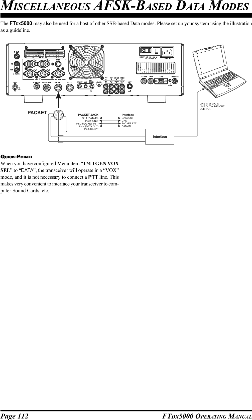

![Page 114 FTDX5000 OPERATING MANUALYou may connect an after-market transverter to the rear panel TRV jack. The output frequency is selectable from 14, 28,and 50 MHz, and the output level is approximately –10 dBm (0.1 mW) at 50 Ohms.SETUP ABOUT THE TRANSVERTER OUTPUT TERMINAL1. Press the [MENU] button briefly to enter the Menumode.2. Rotate the (VFO-A)[SELECT] knob to select Menuitem “150 TUNE MY BAND”.3. Rotate the (VFO-B)[SELECT] knob to select the de-sired input frequency band of the transverter in menuitem (T14M OFF, T28M OFF, or T50M OFF ).4. Press the [ENT] button (one of the [BAND] buttons)to change the parameter to “ON” (the “OFF” notationwill change to “ON”).5. Rotate the (VFO-A)[SELECT] knob to select Menuitem “172 TGEN ETX-GND”.6. Rotate the (VFO-B)[SELECT] knob to set this Menuitem to “ENABLE” to enable the internal relay con-nected to the rear panel TX GND jack.7. Press and hold the [MENU] button for at least two sec-onds to save the new setting, and exit to normal opera-tion.Setting the Transverter Frequency OffsetYou may set up the frequency display so that it shows thefrequencies of the transverter operating band (instead ofthe 28 MHz band frequencies used as the “IF” on yourFTDX5000).Example: Setting up the FTDX5000 display for use with a144 MHz Transverter1. Connect the 144 MHz transverter to the FTDX5000.2. Press the [MENU] button briefly, to enter the Menumode.3. Rotate the (VFO-A)[SELECT] knob to select theMenu item which designates the input frequency bandfrom the transverter (040 GENE TRV 14M, 041GENE TRV 28M, or 042 GENE TRV 50M).4. Rotate the (VFO-B)[SELECT] knob to select“44MHz” on the display.5. Press and hold the [MENU] button in for at least twoseconds to save the new setting and exit.The “100 MHz” digit of the frequency is not displayed,so when you are operating on 2 meters and see “45MHz” on the frequency readout, this indicates “145MHz” instead.ADVICE:With the setup described above, tuning the actual operat-ing range of the FTDX5000 will correspond to transverteroperating frequency of 144-145 MHz, with “44-45” beingdisplayed on the front panel of the transceiver.(VFO-B)[SELECT] Knob[MENU] Button(VFO-A)[SELECT] Knob[ENT] Button](https://usermanual.wiki/Yaesu-Musen/20361X61.Users-Manual-2/User-Guide-1234777-Page-41.png)
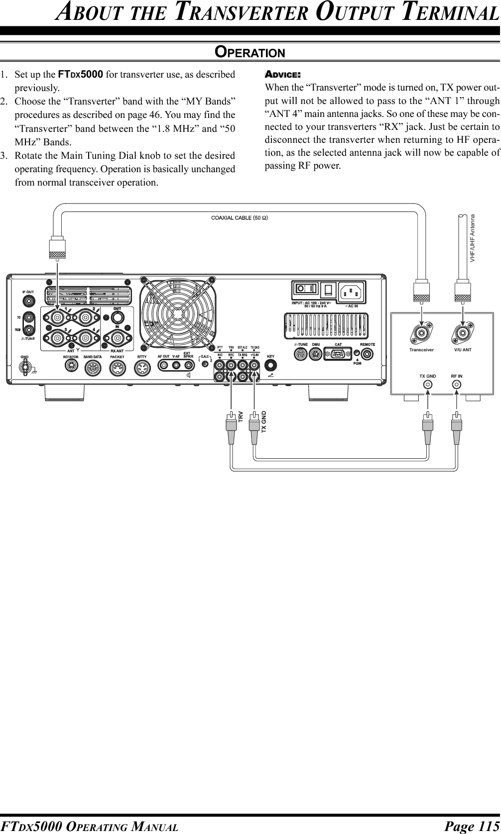
![Page 116 FTDX5000 OPERATING MANUALMENU MODEThe Menu system of the FTDX5000 provides extensive customization capability, so you can set up your transceiver just theway you want to operate it. The Menu items are grouped by general utilization category, and are numbered from “001 AGCFST DLY” to “176 TGEN EMRGNCY.”USING THE MENU1. Press the [MENU] button momentarily, to engage theMenu mode.The SUB DISPLAY-I window will show the MenuNumber and Menu Group name, while the SUB DIS-PLAY-II window will show the Menu item; the SUBDISPLAY-III window shows the current setting of thecurrently-selected Menu item.2. Rotate the (VFO-A)[SELECT] knob to select theMenu item you wish to work on.3. Rotate the (VFO-B)[SELECT] knob to change the cur-rent setting of the selected Menu item.ADVICE:Press the [CLEAR] button momentarily to reset theselected Menu item to the factory default value.4. When you have finished making your adjustments,press and hold in the [MENU] button for two secondsto save the new setting and exit to normal operation. Ifyou only momentarily press the [MENU] button, thenew settings will not be retained.Menu Mode ResetYou may reset all the Menu settings to their original factory defaults, if desired.1. Turn the front panel [POWER] switch off.2. Press and hold in the [MENU] button, and while holding it in, press the [POWER] switch to turn the transceiverback on. Now release the [MENU] button.(VFO-B)[SELECT] Knob[MENU] Button(VFO-A)[SELECT] Knob[CLEAR] Button](https://usermanual.wiki/Yaesu-Musen/20361X61.Users-Manual-2/User-Guide-1234777-Page-43.png)
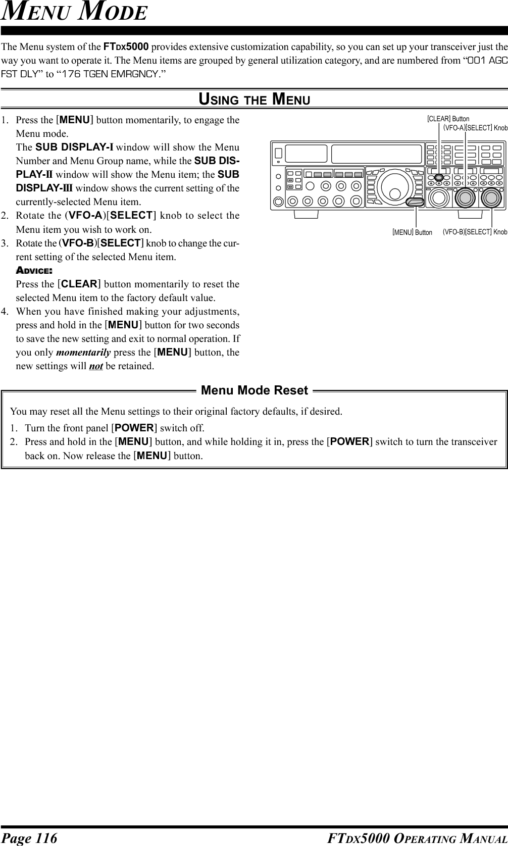
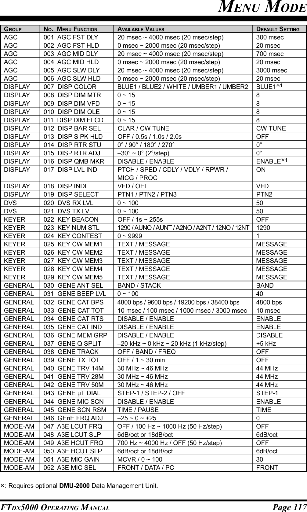
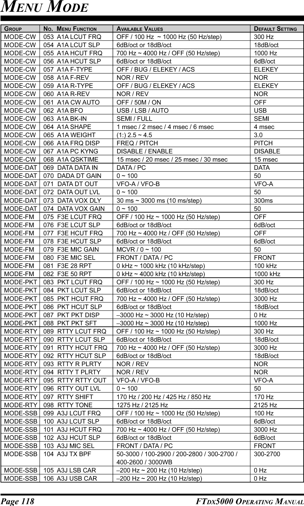
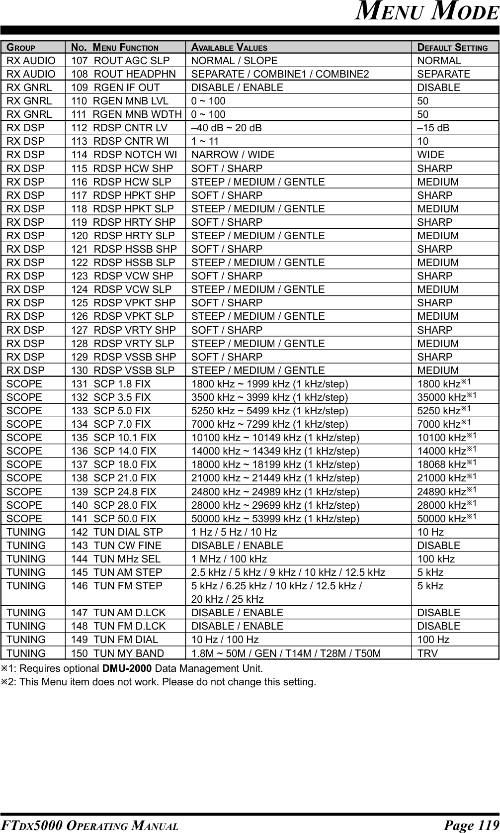
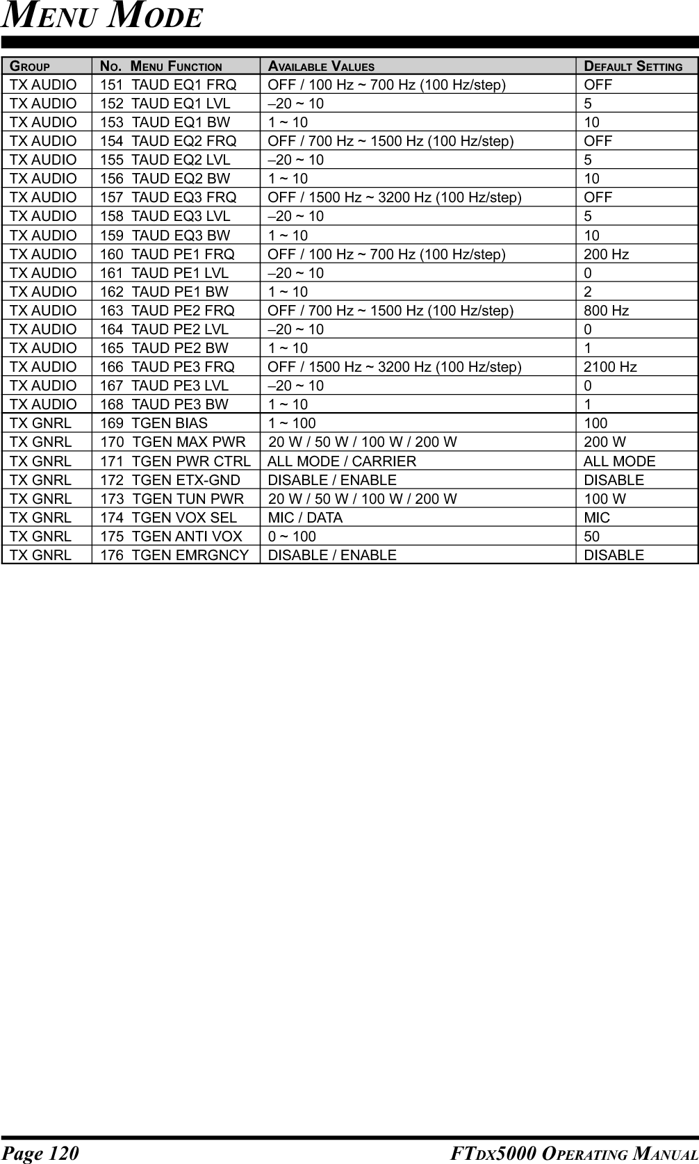
![Page 122 FTDX5000 OPERATING MANUAL014 DISP RTR STUFunction: Selects the starting point of your rotatorcontroller’s indicator needle.Available Values: 0° / 90° / 180° / 270°Default Setting: 0°015 DISP RTR ADJFunction: Adjusts the indicator needle precisely to thestarting point set in menu item “014 DISP RTR STU”.Available Values: –30° ~ 0° (2°/step)Default Setting: 0°016 DISP QMB MKRFunction: Enables/Disables the QMB Marker (White ar-row “”) to display on the Spectrum Band Scope whenthe optional DMU-2000 Data Management Unit is con-nected.Available Values: DISABLE / ENABLEDefault Setting: ENABLEADVICE:If the optional DMU-2000 Data Management Unit is notconnected, this adjustment has no effect.017 DISP LVL INDFunction: Enables/Disables the Main Display to show thefrequency or value while each enabled knob is turned.Available Values: PTCH (PITCH) / SPED (SPEED) /CDLY (CW DELAY) / VDLY (VOX DEALAY) / RPWR(RF POWER) / MICG (MIC GAIN) / PROC (PROCES-SOR GAIN)To disable the “function,” rotate the (VFO-B)[SELECT]knob to recall the “function” to be disabled, then press the[ENT] key (one of the [BAND] buttons) to change thissetting to “OFF”. Repeat the same procedures to enable afunction (setting it to “ON”).018 DISP INDIFunction: Select the indicator location of the current valuewhen adjusting the following knobs.Available Values: VFD / OELDefault Setting: VFDVFD: The current value will show for 3-seconds in thelower right corner of the Main Display when-ever the following knob is turned.OEL: The current value will show for 3-seconds in theSUB DISPLAY-III window whenever the fol-lowing knob is turned.:MIC, RF PWR, SPEED, PITCH, DELAY, andPITCH knobDISPLAY GROUP019 DISP SELECTFunction: Selects the display pattern of the SUB DIS-PLAY-II and SUB DISPLAY-III windows.Available Values: PTN1 / PTN2 / PTN3Default Setting: PTN2PTN1: Generally, the current value is not indicated inthe window, only the graphic is depicted. Whenthe [SELECT] knob is rotated, the currentvalue will appear under the graphical display.Three seconds after the turning of the [SE-LECT] knob is stopped, the current value in-dication disappears.PTN2: Generally, the current value is indicated withthe small characters and graphical display.When the [SELECT] knob is rotated, the cur-rent value indication becomes large characters.Three seconds after the turning of the [SE-LECT] knob is stopped, the current value in-dication returns to small characters.PTN3: The current value always indicated with thelarge characters and graphical display.MENU MODEDVS GROUP020 DVS RX LVLFunction: Sets the audio output level from the voicememory.Available Values: 0 ~ 100Default: 50021 DVS TX LVLFunction: Sets the microphone input level to the voicememoryAvailable Values: 0 ~ 100Default: 50PTN1PTN2PTN3GENERAL WHILE ADJUSTINGSUB DISPLAY EXAMPLES (CONTOUR OPERATION)](https://usermanual.wiki/Yaesu-Musen/20361X61.Users-Manual-2/User-Guide-1234777-Page-49.png)
![Page 123FTDX5000 OPERATING MANUALKEYER GROUP026 KEY CW MEM2Function: Permits entry of the CW message for messageregister 2.Available Values: TEXT / MESSAGEDefault Setting: MESSAGETEXT: You may enter the CW message from theFH-2’s keypad.MESSAGE: You may enter the CW message from theCW keyer.027 KEY CW MEM3Function: Permits entry of the CW message for messageregister 3.Available Values: TEXT / MESSAGEDefault Setting: MESSAGETEXT: You may enter the CW message from theFH-2’s keypad.MESSAGE: You may enter the CW message from theCW keyer.028 KEY CW MEM4Function: Permits entry of the CW message for messageregister 4.Available Values: TEXT / MESSAGEDefault Setting: MESSAGETEXT: You may enter the CW message from theFH-2’s keypad.MESSAGE: You may enter the CW message from theCW keyer.029 KEY CW MEM5Function: Permits entry of the CW message for messageregister 5.Available Values: TEXT / MESSAGEDefault Setting: MESSAGETEXT: You may enter the CW message from theFH-2’s keypad.MESSAGE: You may enter the CW message from theCW keyer.MENU MODE022 KEY BEACONFunction: Sets the interval time between repeats of thebeacon message.Available Values: OFF / 1s ~ 255 secDefault Setting: OFF023 KEY NUM STLFunction: Selects the Contest Number “Cut” format foran imbedded contest number.Available Values: 1290 / AUNO / AUNT / A2NO / A2NT/12NO / 12NTDefault Setting: 12901290: Does not abbreviate the Contest NumberAUNO: Abbreviates to “A” for “One,” “U” for “Two,”“N” for “Nine,” and “O” for “Zero.”AUNT: Abbreviates to “A” for “One,” “U” for “Two,”“N” for “Nine,” and “T” for “Zero.”A2NO: Abbreviates to “A” for “One,” “N” for “Nine,”and “O” for “Zero.”A2NT: Abbreviates to “A” for “One,” “N” for “Nine,”and “T” for “Zero.”12NO: Abbreviates to “N” for “Nine,” and “O” for“Zero.”12NT: Abbreviates to “N” for “Nine,” and “T” for“Zero.”024 KEY CONTESTFunction: Enters the initial contest number that will in-crement/decrement after sending during contest QSOs.Available Values: 0 ~ 9999Default Setting: 1ADVICE:Press the [CLEAR] button to reset the contest number to“1.”025 KEY CW MEM1Function: Permits entry of the CW message for messageregister 1.Available Values: TEXT / MESSAGEDefault Setting: MESSAGETEXT: You may enter the CW message from theFH-2’s keypad.MESSAGE: You may enter the CW message from theCW keyer.](https://usermanual.wiki/Yaesu-Musen/20361X61.Users-Manual-2/User-Guide-1234777-Page-50.png)
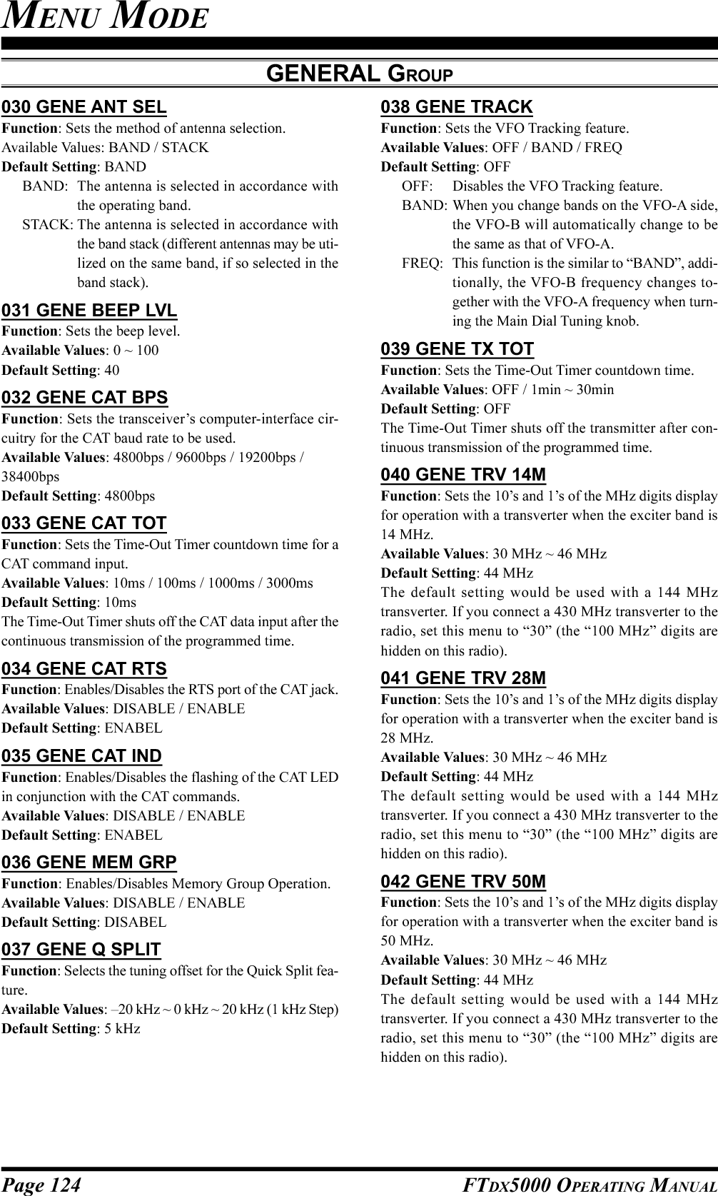
![Page 125FTDX5000 OPERATING MANUAL043 GENE µT DIALFunction: Selects the µ-TUNE mode.Available Values: STEP-1 / STEP-2 / OFFDefault Setting: STEP-1STEP-1: Activates the µ-TUNE system using“COARSE” steps of the [SELECT] knob (2steps/click) on the 7 MHz and lower amateurbands. On the 10/14 MHz bands, “FINE”steps of [SELECT] knob (1 step/click) willbe used.STEP-2: Activates the µ-TUNE system using “FINE”steps of the [SELECT] knob (1 step/click)on the 14 MHz and lower amateur bands onthe Main band (VFO-A).OFF: Disables the µ-TUNE system. Activates theVRF feature on the 14 MHz and lower ama-teur bands on the main band (VFO-A).ADVICE:If the optional RF µTuning Kit is not connected, this ad-justment has no effect.044 GENE MIC SCNFunction: Enables/disables scanning access via themicrophone’s [UP]/[DWN] keys.Available Values: DISABLE / ENABLEDefault Setting: ENABLE045 GENE SCN RSMFunction: Selects the Scan Resume mode.Available Values: TIME / PAUSEDefault Setting: TIMETIME: The scanner will hold for five seconds, thenresume whether or not the other station is stilltransmitting.PAUSE: The scanner will hold until the signal disap-pears, then will resume after one second.046 GENE FRQ ADJFunction: Adjusts the reference oscillator.Available Values: –25 ~ 0 ~ 25Default Setting: 0Connect a 50-Ohm dummy load and frequency counter tothe antenna jack; adjust the (VFO-B)[SELECT] knob sothat the frequency counter reading is same as the VFOfrequency while pressing the PTT switch.ADVICE:Do not perform this Menu item unless you have a high-performance frequency counter. Perform this Menu itemafter aging the transceiver and frequency counter suffi-ciently (at least 30 minutes).MODE-AM GROUP047 A3E LCUT FRQFunction: Selects the cutoff frequency of the lower sideof the RX audio filter in the AM mode.Available Values: OFF / 100 Hz ~ 1000Hz (50 Hz/step)Default Setting: OFF048 A3E LCUT SLPFunction: Selects the filter slope of the lower side of theRX audio filter in the AM mode.Available Values: 6dB/oct or 18dB/octDefault Setting: 6dB/oct049 A3E HCUT FRQFunction: Selects the cutoff frequency of the upper sideof the RX audio filter in the AM mode.Available Values: OFF / 700Hz ~ 4000Hz (50 Hz/step)Default Setting: OFF050 A3E HCUT SLPFunction: Selects the filter slope of the upper side of theRX audio filter in the AM mode.Available Values: 6dB/oct or 18dB/octDefault Setting: 6dB/oct051 A3E MIC GAINFunction: Sets the microphone gain for the AM mode.Available Values: MCVR / 0 ~ 100Default Setting: 30When this menu is set to “MCVR”, you may adjust themicrophone gain using the front panel’s [MIC] knob.052 A3E MIC SELFunction: Selects the microphone to be used in the AMmode.Available Values: FRONT / DATA / PCDefault Setting: FRONTFRONT: Selects the microphone connected to the frontpanel’s MIC jack while using the AM mode.DATA: Selects the microphone connected to pin 1 ofthe PACKET Jack while using the AM mode.PC: This parameter is for future expansion of thistransceiver’s capabilities, but at this time isnot supported.MENU MODEGENERAL GROUP](https://usermanual.wiki/Yaesu-Musen/20361X61.Users-Manual-2/User-Guide-1234777-Page-52.png)
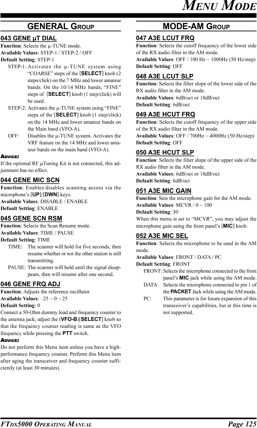
![Page 127FTDX5000 OPERATING MANUAL063 A1A BK-INFunction: Sets the CW “break-in” mode.Available Values: SEMI / FULLDefault Setting: SEMISEMI: The transceiver will operate in the semi break-in mode. The delay (receiver recovery) time isset by the front panel [DELAY] knob.FULL: The transceiver will operate in the full break-in (QSK) mode.064 A1A SHAPEFunction: Selects the CW carrier wave-form shape (rise/fall times).Available Values: 1ms / 2ms / 4ms / 6msDefault Setting: 4 ms065 A1A WEIGHTFunction: Sets the Dot:Dash ratio for the built-in elec-tronic keyer.Available Values: (1:) 2.5 ~ 4.5Default Setting: 3.0066 A1A FRQ DISPFunction: Selects the frequency Display Format for theCW mode.Available Values: FREQ / PITCHDefault Setting: PITCHFREQ: Displays the receiver carrier frequency, with-out any offset added. When changing modesbetween SSB and CW, the frequency displayremains constant.PITCH: This frequency display reflects the addedBFO offset.067 A1A PC KYNGFunction: Enables/disables CW keying from the“PACKET PTT” terminal (pin 3) on the rear panel’sPACKET jack while operating in the CW mode.Available Values: DISABLE / ENABLEDefault Setting: DISABLE068 A1A QSK TIMEFunction: Selects the time delay between when the PTTis keyed and the carrier is transmitted during QSK opera-tion when using the internal keyer.Available Values: 15ms / 20ms / 25ms / 30 msDefault Setting: 15msMODE-DAT GROUP069 DATA DATA INFunction: Selects the data input path to be used in thePKT mode.Available Values: DATA / PCDefault Setting: DATADATA: Uses the data input line connected to pin 1 ofthe PACKET jack while using the PKT mode.PC: This parameter is for future expansion of thistransceiver’s capabilities, but at this time isnot supported.070 DATA DT GAINFunction: Sets the data input level from the TNC to theAFSK modulator.Available Values: 0 ~ 100Default Setting: 50071 DATA DT OUTFunction: Selects the receiver to be connected to the dataoutput port (pin 4) of the PACKET jack.Available Values: VFO-A / VFO-BDefault Setting: VFO-A072 DATA OUT LVLFunction: Sets the AFSK data output level at the outputport (pin 4) of the PACKET jack.Available Values: 0 ~ 100Default Setting: 50073 DATA VOX DLYFunction: Adjusts the “VOX” delay (receiver recovery)time in the PKT mode.Available Values: 30ms ~ 3000ms (10 ms/step)Default Setting: 300ms074 DATA VOX GAINFunction: Adjusts the “VOX” gain in the PKT mode.Available Values: 0 ~ 100Default Setting: 50MODE-CW GROUPMENU MODE](https://usermanual.wiki/Yaesu-Musen/20361X61.Users-Manual-2/User-Guide-1234777-Page-54.png)
![Page 128 FTDX5000 OPERATING MANUALMODE-PKT GROUP083 PKT LCUT FRQFunction: Selects the cutoff frequency of the lower sideof the RX audio filter in the Packet mode.Available Values: OFF / 100Hz ~ 1000Hz (50 Hz/step)Default Setting: 300Hz084 PKT LCUT SLPFunction: Selects the filter slope of the lower side of theRX audio filter in the Packet mode.Available Values: 6dB/oct or 18dB/octDefault Setting: 18dB/oct085 PKT HCUT FRQFunction: Selects the cutoff frequency of the upper sideof the RX audio filter in the Packet mode.Available Values: OFF / 700Hz ~ 4000Hz (50 Hz/step)Default Setting: 3000Hz086 PKT HCUT SLPFunction: Selects the filter slope of the upper side of theRX audio filter in the Packet mode.Available Values: 6dB/oct or 18dB/octDefault Setting: 18dB/oct087 PKT PKTDISPFunction: Sets the packet frequency display offset.Available: –3000Hz ~ 3000Hz (10 Hz/step)Default: 0Hz088 DATA PKT SFTFunction: Sets the carrier point during the SSB packetoperation.Available: –3000Hz ~ 3000Hz (10 Hz/step)Default: 1000Hz (typical center frequency for PSK31, etc.)MENU MODEMODE-FM GROUP075 F3E LCUT FRQFunction: Selects the cutoff frequency of the lower sideof the RX audio filter in the FM mode.Available Values: OFF / 100Hz ~ 1000Hz (50 Hz/step)Default Setting: OFF076 F3E LCUT SLPFunction: Selects the filter slope of the lower side of theRX audio filter in the FM mode.Available Values: 6dB/oct or 18dB/octDefault Setting: 6dB/oct077 F3E HCUT FRQFunction: Selects the cutoff frequency of the upper sideof the RX audio filter in the FM mode.Available Values: OFF / 700Hz ~ 4000Hz (50 Hz/step)Default Setting: OFF078 F3E HCUT SLPFunction: Selects the filter slope of the upper side of theRX audio filter in the FM mode.Available Values: 6dB/oct or 18dB/octDefault Setting: 6dB/oct079 F3E MIC GAINFunction: Sets the microphone gain for the FM mode.Available Values: MCVR / 0 ~ 100Default Setting: 50When this menu is set to “MCVR”, you may adjust themicrophone gain using the front panel [MIC] knob.080 F3E MIC SELFunction: Selects the microphone to be used on the FMmode.Available Values: FRONT / DATA / PCDefault Setting: FRONTFRONT: Selects the microphone connected to the frontpanel MIC jack while using the FM mode.DATA: Selects the microphone connected to pin 1 ofthe PACKET Jack while using the FM mode.PC: This parameter is for future expansion of thistransceiver’s capabilities, but at this time isnot supported.081 F3E 28 RPTFunction: Sets the magnitude of the repeater shift on the28 MHz band.Available Values: 0kHz ~ 1000kHz (10 kHz/step)Default Setting: 100kHz082 F3E 50 RPTFunction: Sets the magnitude of the repeater shift on the50 MHz band.Available Values: 0kHz ~ 4000kHz (10 kHz/step)Default Setting: 1000kHz](https://usermanual.wiki/Yaesu-Musen/20361X61.Users-Manual-2/User-Guide-1234777-Page-55.png)
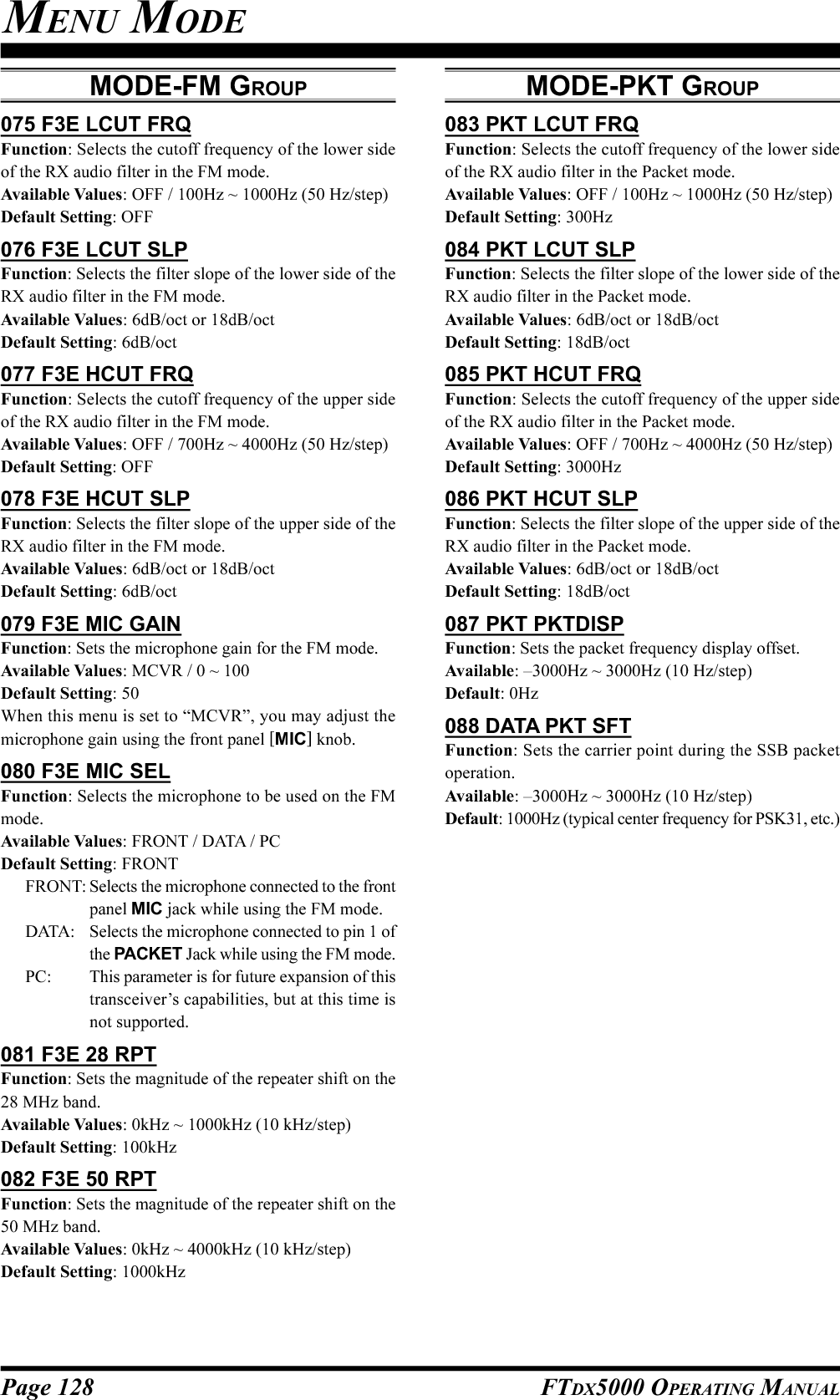
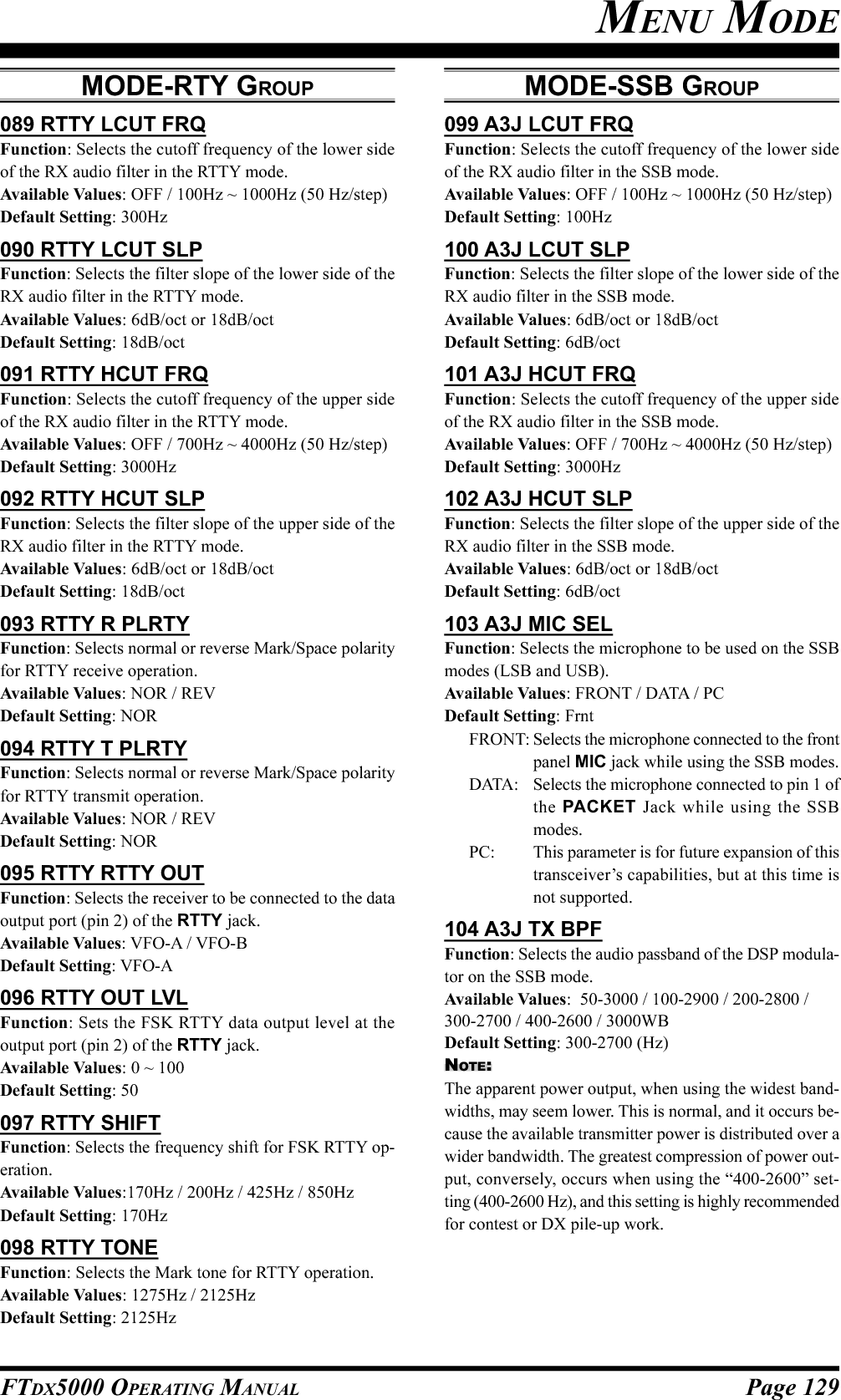
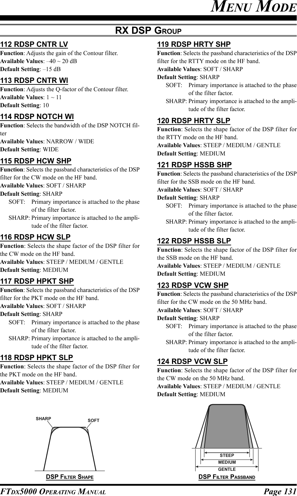

![Page 133FTDX5000 OPERATING MANUALMENU MODE136 SCP 14.0 FIXFunction: Selects the scan start frequency of the FIX modeSpectrum Scope while monitoring on the 20 m amateurband.Available Values: 14000kHz ~ 14349kHz (1 kHz/step)Default Setting: 14000kHz137 SCP 18.0 FIXFunction: Selects the scan start frequency of the FIX modeSpectrum Scope while monitoring on the 17 m amateurband.Available Values: 18000kHz ~ 18199kHz (1 kHz/step)Default Setting: 18068kHz138 SCP 21.0 FIXFunction: Selects the scan start frequency of the FIX modeSpectrum Scope while monitoring on the 15 m amateurband.Available Values: 21000kHz ~ 21449kHz (1 kHz/step)Default Setting: 21000kHz139 SCP 24.8 FIXFunction: Selects the scan start frequency of the FIX modeSpectrum Scope while monitoring on the 12 m amateurband.Available Values: 24800kHz ~ 24989kHz (1 kHz/step)Default Setting: 24890kHz140 SCP 28.0 FIXFunction: Selects the scan start frequency of the FIX modeSpectrum Scope while monitoring on the 10 m amateurband.Available Values: 28000kHz ~ 29699kHz (1 kHz/step)Default Setting: 28000kHz141 SCP 50.0 FIXFunction: Selects the scan start frequency of the FIX modeSpectrum Scope while monitoring on the 6 m amateur band.Available Values: 50000kHz ~ 53999kHz (1 kHz/step)Default Setting: 50000kHzTUNING GROUP142 TUN DIAL STPFunction: Setting of the Tuning Dial knob’s tuning speedexcept the FM and FM-PKT modes.Available Values: 1Hz / 5Hz / 10HzDefault Setting: 10Hz143 TUN CW FINEFunction: Enabling/disabling of the “Fine” tuning speedin the CW, RTTY, and PKT-SSB modes.Available Values: DISABLE / ENABLEDefault Setting: DISABLEENABLE: Tuning in 1 Hz steps on the CW, RTTY,and PKT-SSB modes.DISABLE: Tuning according to the steps determinedvia menu item “142 TUN DIAL STP”.144 TUN MHz SELFunction: Selects the tuning steps of the [(DOWN)] /[(UP)] key.Available Values: 1MHz / 100kHzDefault Setting: 100kHz145 TUN AM STEPFunction: Selects the tuning steps for the microphone’s[UP]/[DWN] keys in the AM mode.Available Values: 2.5kHz / 5kHz / 9kHz / 10kHz / 12.5 kHzDefault Setting: 5kHz146 TUN FM STEPFunction: Selects the tuning steps for the microphone’s[UP]/[DWN] keys in the FM and FM-PKT modes.Available Values: 5kHz / 6.25kHz / 10kHz / 12.5kHz /20kHz / 25kHzDefault Setting: 5kHz147 TUN AM D.LCKFunction: Select whether the Main Tuning Dial knob and[CLAR(VFO-B)] knob shall be “Enabled” or “Disabled”on the AM mode.Available Values: DISABLE / ENABLEDefault Setting: DISABLE148 TUN FM D.LCKFunction: Select whether the Main Tuning Dial knob and[CLAR(VFO-B)] knob shall be “Enabled” or “Disabled”on the FM mode.Available Values: DISABLE / ENABLEDefault Setting: DISABLE149 TUN FM DIALFunction: Setting of the Tuning Dial knob’s tuning speedin the FM mode.Available Values: 10Hz / 100HzDefault Setting: 100HzSCOPE GROUP](https://usermanual.wiki/Yaesu-Musen/20361X61.Users-Manual-2/User-Guide-1234777-Page-60.png)
![Page 134 FTDX5000 OPERATING MANUALMENU MODETX AUDIO GROUP151 TAUD EQ1 FRQFunction: Selects the center frequency of the lower rangefor the parametric microphone equalizer.Available Values: OFF / 100Hz ~ 700Hz (100 Hz/step)Default Setting: OFFOFF: The equalizer gain and Q-factor areset to factory defaults (flat).100Hz ~ 700Hz: Center frequencies of 100 Hz ~ 700Hz. You may adjust the equalizergain and Q-factor at this selectedaudio frequency via menu items“152 TAUD EQ1 LVL” and “153TAUD EQ1 BW”.152 TAUD EQ1 LVLFunction: Adjusts the equalizer gain of the low range ofthe parametric microphone equalizer.Available Values: –20 ~ 10Default Setting: 5153 TAUD EQ1 BWFunction: Adjusts the Q-factor of the low range of theparametric microphone equalizer.Available Values: 1 ~ 10Default Setting: 10154 TAUD EQ2 FRQFunction: Selects the center frequency of the middlerange for the parametric microphone equalizer.Available Values: OFF / 700Hz ~ 1500Hz (100 Hz/step)Default Setting: OFFOFF: The equalizer gain and Q-factor areset to factory defaults (flat).700Hz ~ 1500Hz: Center frequencies of 700 Hz ~1500 Hz. You may adjust the equal-izer gain and Q-factor at this se-lected audio frequency via menuitems “155 TAUD EQ2 LVL” and“156 TAUD EQ2 BW”.155 TAUD EQ2 LVLFunction: Adjusts the equalizer gain of the middle rangeof the parametric microphone equalizer.Available Values: –20 ~ 10Default Setting: 5156 TAUD EQ2 BWFunction: Adjusts the Q-factor of the middle range ofthe parametric microphone equalizer.Available Values: 1 ~ 10Default Setting: 10150 TUN MY BANDFunction: Programs a band to be skipped while selectingbands using the [CLAR(VFO-B)] knob.Available Values: 1.8M ~ 50M / GEN / T14M / T28M /T50MDefault Setting: 1.8M ~ 50M / GEN: ON, T14M / T28M / T50M: OFFTo program the band to be skipped, rotate the (VFO-B)[SELECT] knob to recall the band to be skipped whileselecting bands via the [CLAR(VFO-B)] knob, then pressthe [ENT] key (one of the [BAND] buttons) to change thissetting to “OFF”. Repeat the same procedures to cancel thesetting (change the “OFF” notation to “ON”).TUNING GROUP](https://usermanual.wiki/Yaesu-Musen/20361X61.Users-Manual-2/User-Guide-1234777-Page-61.png)
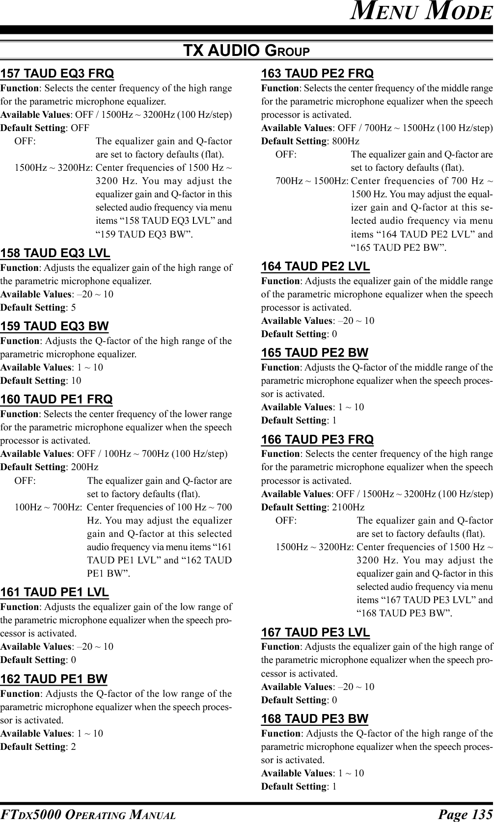
![Page 136 FTDX5000 OPERATING MANUALTX GNRL GROUP169 TGEN BIASFunction: Adjusts the Bias level of the Final Amplifierwhile in “Class-A” operation.Available Values: 1 ~ 100Default Setting: 100170 TGEN MAX PWRFunction: Selects a maximum output power limit.Available Values: 20W / 50W / 100W / 200WDefault Setting: 200W171 TGEN PWR CTRLFunction: Configures the [RF PWR] knob.Available Values: ALL MODE / CARRIERDefault Setting: ALL MODEALL MODE: The [RF PWR] knob is enabled on allmodes.CARRIER: The [RF PWR] knob is enabled in allmodes except SSB. In this configuration,the SSB output power will be set tomaximum, regardless of the [RF PWR]knob’s position.172 TGEN ETX-GNDFunction: Enables/Disables the TX GND jack on the rearpanel.Available Values: DISABLE / ENABLEDefault Setting: DISABLE173 TGEN TUN PWRFunction: Selects a maximum output power limit for driv-ing the input circuit of an external linear RF amplifier whiletuning (while using the Remote Control function of thelinear RF amplifier).Available Values: 20W / 50W / 100W / 200WDefault Setting: 100W174 TGEN VOX SELFunction: Selects the audio input source for triggering TXduring VOX operation.Available Values: MIC / DATADefault Setting: MICMIC: The VOX function will be activated by micro-phone audio input.DATA: The VOX function will be activated by dataaudio input.175 TGEN ANTI VOXFunction: Adjusts the Anti-VOX Trip Gain, which is thelevel of negative AF feedback of receiver audio to themicrophone, to prevent receiver audio from activating thetransmitter (via the microphone) during VOX operation.Available Values: 1 ~ 100Default Setting: 100176 TGEN EMRGNCYFunction: Enables Tx/Rx operation on the Alaska Emer-gency Channel, 5167.5 kHz.Available Values: DISABLE / ENABLEDefault Setting: DISABLEWhen this Menu Item is set to “ENABLE”, the spot fre-quency of 5167.5 kHz will be enabled. The Alaska Emer-gency Channel will be found between the Memory chan-nels “P-1” and “01 (or 1-01)”.IMPORTANT:The use of this frequency is restricted to stations operat-ing in or near Alaska, and only for emergency purposes(never for routine operations). See §97.401(c) of the FCC’sregulations for details.MENU MODE](https://usermanual.wiki/Yaesu-Musen/20361X61.Users-Manual-2/User-Guide-1234777-Page-63.png)
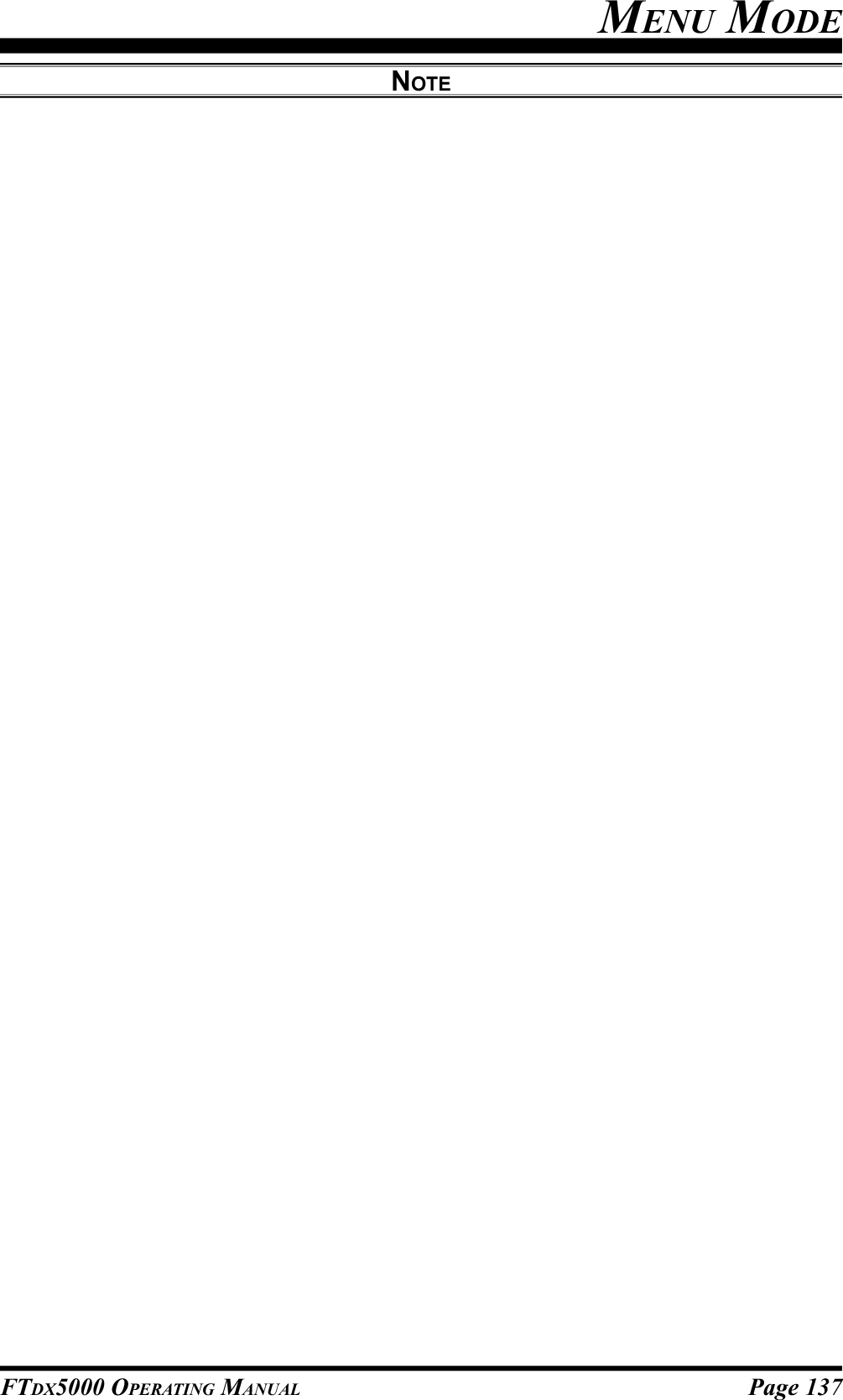
![Page 138 FTDX5000 OPERATING MANUALSPECIFICATIONSGENERALRx Frequency Range: 30 kHz - 60 MHz (operating)1.8 - 29.7 MHz, 50 - 54 MHz (specified performance, Amateur bands only)Tx Frequency Ranges: 1.8 - 29.7 MHz, 50 - 54 MHz (Amateur bands only)5.16750MHz, 5.33200MHz, 5.34800MHz,5.36800MHz, 5.37300MHz, 5.40500MHz (USA version only)Frequency Stability: ±0.05 ppm (MP version, after 1 minute @+14 °F ~ +140 °F [–10 °C ~ +60 °C])±0.5 ppm (after 1 minute @+14 °F ~ +140 °F [–10 °C ~ +60 °C])Operating Temperature Range: +14 °F ~ +140 °F (–10 °C ~ +60 °C)Emission Modes: A1A (CW), A3E (AM), J3E (LSB, USB), F3E (FM),F1B (RTTY), F1D (PACKET), F2D (PACKET)Frequency Steps: 1/5/10 Hz (SSB,CW, & AM), 100 Hz (FM)Antenna Impedance: 50 Ohms, unbalanced16.7 - 150 Ohms, unbalanced (Tuner ON, 1.8 - 29.7 MHz Amateur bands)25 - 100 Ohms, unbalanced (Tuner ON, 50 MHz Amateur band)Power Consumption: Rx (no signal) 70 VA(@117 VAC) Rx (signal present) 80 VATx (200 W) 720 VASupply Voltage: AC 90 V - AC 264 VDimensions (WxHxD): 18.2” x 5.3” x 15.3” (462 x 135 x 389 mm) w/o knob and connectorWeight (approx.): 46.3 lbs (21 kg)TRANSMITTERPower Output: 10 - 200 watts (CW, LSB, USB, FM, RTTY, PKT)5 - 50 watts (AM carrier)10 - 75 watts (Class A: LSB, USB)Modulation Types: J3E (SSB): Balanced,A3E (AM): Low-Level (Early Stage)F3E (FM): Variable ReactanceMaximum FM Deviation: ±5.0 kHz/±2.5 kHzHarmonic Radiation: Better than –60 dB (1.8 - 50 MHz Amateur bands)SSB Carrier Suppression: At least 60 dB below peak outputUndesired Sideband Suppression: At least 60 dB below peak outputAudio Response (SSB): Not more than –6 dB from 300 to 2700 Hz3rd-order IMD: –31 dB @14 MHz, 100 watts PEP–40 dB @14 MHz, Class A: 75 watts PEPBandwidth: 500 Hz (CW)3.0 kHz (LSB, USB)6.0 kHz (AM)16 kHz (FM)Microphone Impedance: 600 Ohms (200 to 10 k Ohms)](https://usermanual.wiki/Yaesu-Musen/20361X61.Users-Manual-2/User-Guide-1234777-Page-65.png)
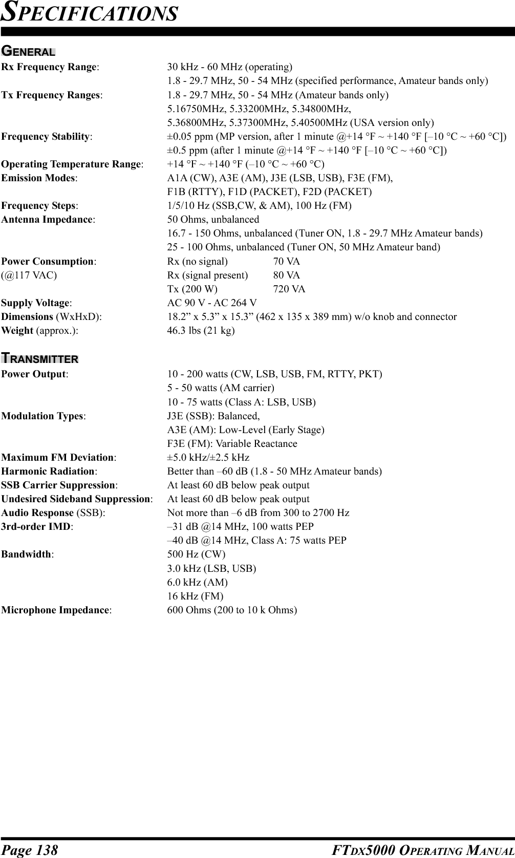
![Page 140 FTDX5000 OPERATING MANUALINSTALLATION OF THE OPTIONAL ROOFING FILTER (XF-126CN)1. Turn the front panel [POWER] switch “off,” then turnthe rear panel’s [POWER] switch “off.”2. Disconnect all the cables from the transceiver.3. Referring to Figure 1, remove the three screws fromeach side of the transceiver and four screws from thetop of the transceiver, then remove the top cover.4. Refer to Figure 2, there is the metal plate on the rightside of the transceiver. A mounting position of the op-tional filter is inside of this. Remove the three screwsaffixing the metal plate, then remove the metal plate.5. Refer to Figure 3, position the filter so that its connec-tors are aligned with the mounting pins on the board,and push it into place.6. Replace the metal plate and its three screws.7. Replace the top cover and its ten screws.8. Filter installation is now complete.9. Connect the all cables to the transceiver.FIGURE 1FIGURE 2FIGURE 3](https://usermanual.wiki/Yaesu-Musen/20361X61.Users-Manual-2/User-Guide-1234777-Page-67.png)