Yaesu Musen 20361X61 HF Transceiver with Scanning Receiver User Manual P65
Yaesu Musen Co., Ltd. HF Transceiver with Scanning Receiver P65
Contents
- 1. Users Manual 1
- 2. Users Manual 2
Users Manual 2
Page 74 FTDX5000 OPERATING MANUAL
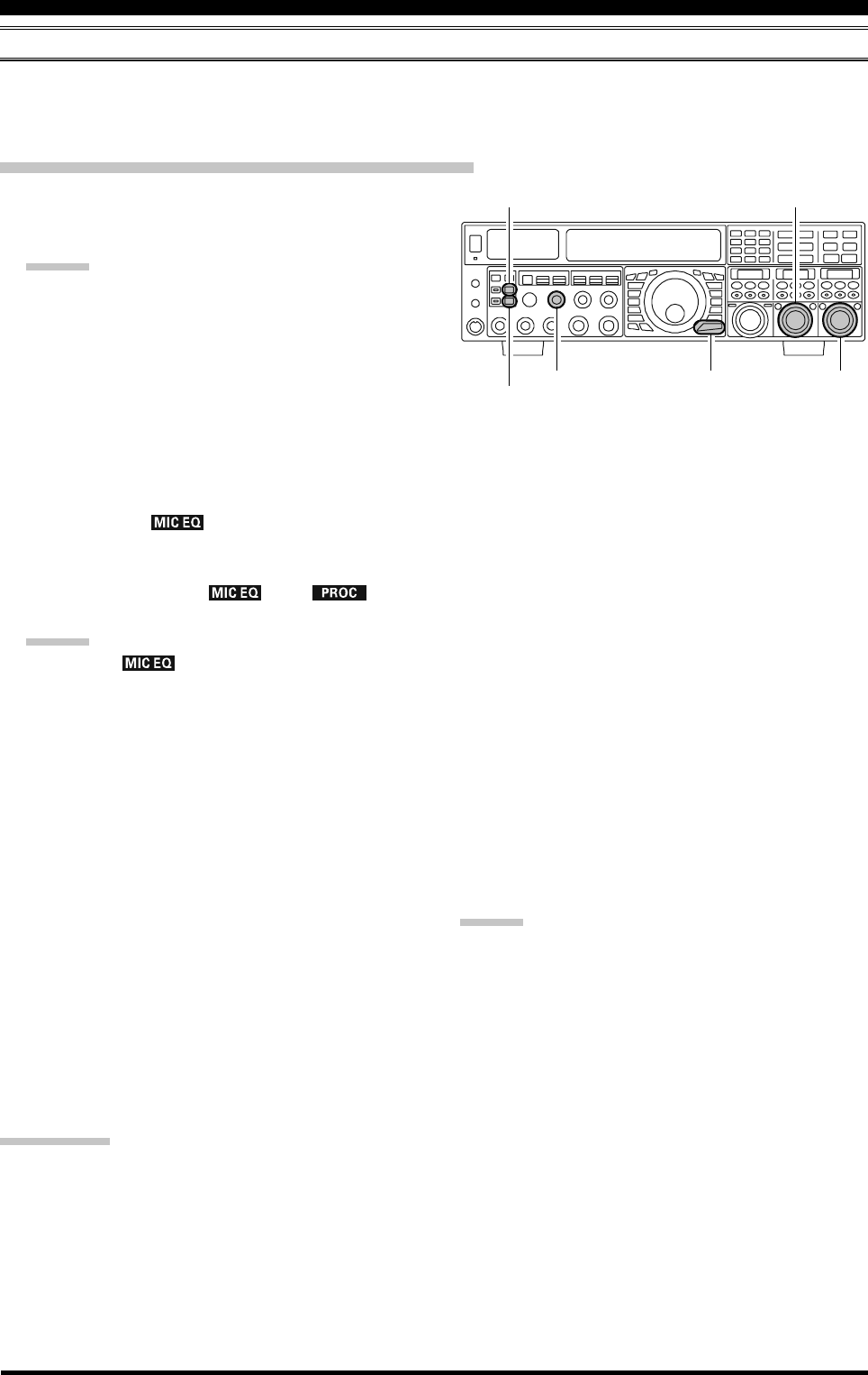
PARAMETRIC MICROPHONE EQUALIZER (SSB/AM/FM MODES)
The FTDX5000 includes a unique Three-Band Parametric Microphone Equalizer, that provides precise, independent con-
trol over the low-, mid-, and treble-ranges in your voice waveform. You may utilize one group of settings when the speech
processor is off, and an another independent group of settings when the speech processor is on.
Setup of the Parametric Microphone Equalizer
1. Connect the microphone to the MIC jack.
2. Set the [RF PWR] knob to its minimum value, to re-
duce interference to other users during adjustment.
ADVICE:
We recommend you consider connecting a dummy
load to one of the Antenna jacks, and monitor your
signal on a separate receiver, to prevent interfer-
ence to other users.
You will have the best chance of hearing the ef-
fects of adjustments if you wear headphones (con-
nected to the monitor receiver) while monitoring
your transmitted signal.
3. To adjust the Parametric Microphone Equalizer while
the speech processor is disabled, press the [PROC]
button until the “ ” icon appears (or blinks) in
the display. To adjust the Parametric Microphone
Equalizer with the speech processor engaged, press the
[PROC] button until the “ ” and “ ” icon
appears in the display.
ADVICE:
A blinking “ ” icon indicates the Parametric
Microphone Equalizer menu settings have all been set
to “OFF”, as described later.
4. Press the [MONI] button, if you want to listen on the
FTDX5000’s internal monitor. Adjust the monitor level
using the [MONI] knob.
5. Press the [MENU] button briefly. The Menu list will
appear in the display.
6. Rotate the (VFO-A)[SELECT] knob to find the
“TAUD” Menu area, which contains Menu items “151”
through “159”; these parameters apply to the adjust-
ment of the Parametric Microphone Equalizer when
the speech processor is disabled. Menu items “160”
through “168” apply to the adjustment of the Paramet-
ric Microphone Equalizer when the speech processor
is engaged.
7. Rotate the (VFO-B)[SELECT] knob to perform ad-
justments to a particular Menu item.
8. Press the PTT switch, and speak into the microphone
while listening to the effects of the changes you are
making (in step 6). Because the overall effect on the
sound will change with each adjustment you make, you
should make several passes through each adjustment
area, to be sure that you are achieving the optimum
setting.
9. When you have completed all adjustments, press and
hold in the [MENU] button for two seconds to save
the new settings and exit to normal operation. If you
only press the [MENU] button momentarily to exit,
any changes you performed will not be stored.
ADVICE:
To roll off excessive bass response in a wide-range studio
microphone, try putting a 10 dB null at 100 Hz with a
bandwidth of “1” or “2,” do about a 3 dB null centered on
800 Hz with a bandwidth of “3,” and then put an 8 dB
peak centered on 2100 Hz with a bandwidth of “1.” These
are starting recommendations; each microphone and user’s
voice will be different, often requiring different settings.
(VFO-B)[SELECT] Knob
[MENU] Button
(VFO-A)[SELECT] Knob
[MONI] Button
[MONI] Knob
[PROC] Button
ENHANCING TRANSMIT SIGNAL QUALITY
QUICK POINT:
The Parametric Equalizer is a unique system for adjusting the signal quality. Because the high, mid, and low audio ranges
may be adjusted so precisely, it is possible to craft a response that provides a more natural and pleasant sound than you have
ever experienced before. Or, the effective “talk power” can be significantly enhanced.
The aspects of configuration that you may adjust with the Parametric Equalizer are:
Center Frequency: The center frequency of each of the three bands may be adjusted.
Gain: The amount of enhancement (or suppression) within each band may be adjusted.
Q: The bandwidth over which the equalization is applied may be adjusted.
Page 75FTDX5000 OPERATING MANUAL
PARAMETRIC MICROPHONE EQUALIZER (SSB/AM/FM MODES)
QQ
QQQ
f3f2f1
100 700Hz
~
700 1500Hz
~
1500 3200Hz
~
Q
+10dB
-10dB
-20dB
Parametric Gain
0 dB
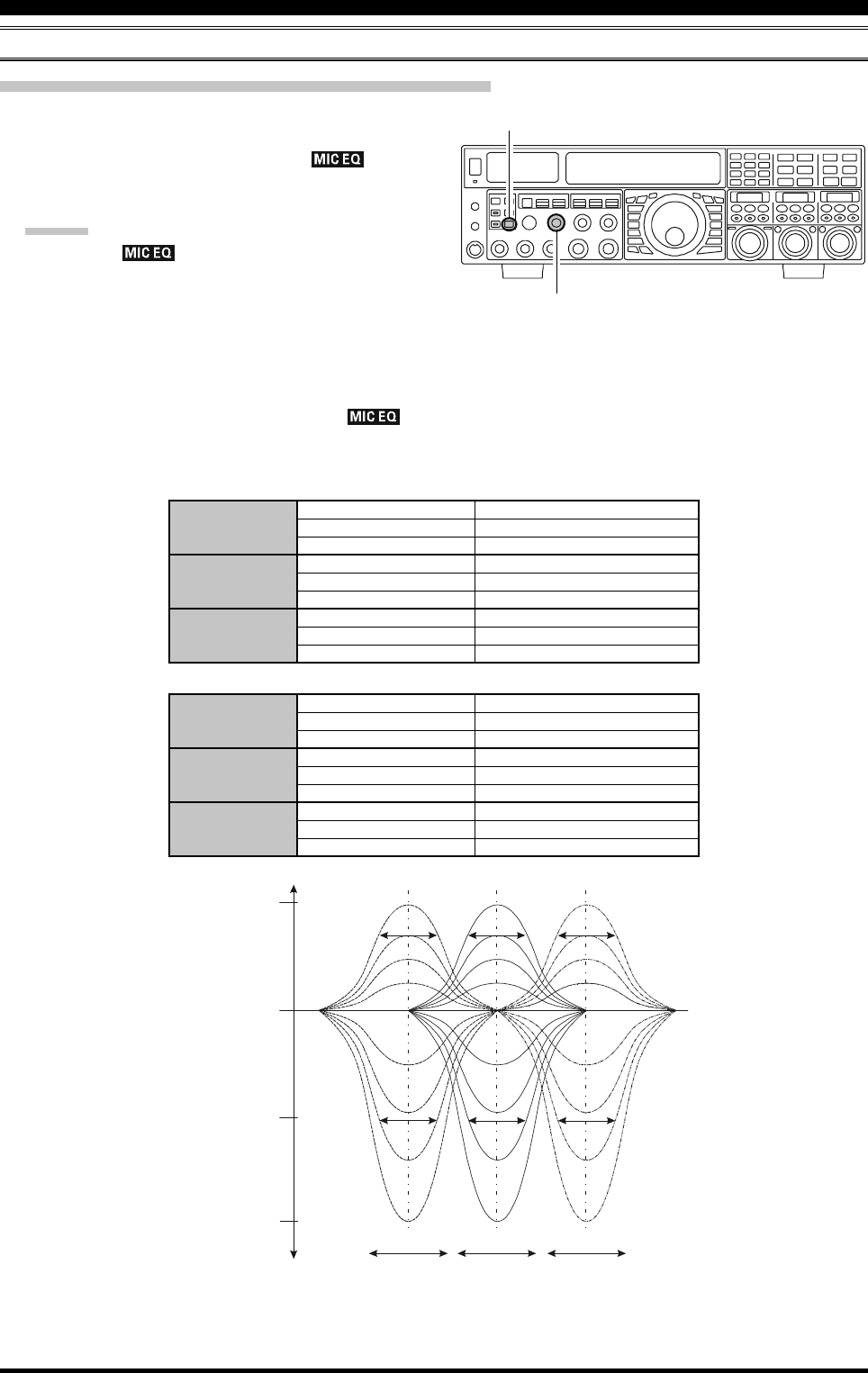
Activating the Parametric Microphone Equalizer
1. Adjust the [MIC] (gain) knob for SSB use, as described
on page 70.
2. Press the [PROC] button briefly. The “ ” icon
will appear in the display, confirming that the Para-
metric Microphone Equalizer is engaged.
ADVICE:
A blinking “ ” icon indicates the Parametric
Microphone Equalizer menu settings have all been set
to “OFF” (“151 TAUD EQ1 FRQ”, “154 TAUD EQ2
FRQ”, and “157 TAUD EQ3 FRQ”).
3. Press the PTT switch on the microphone, and speak
into the microphone in a normal voice level.
4. To switch the Parametric Microphone Equalizer off,
press the [PROC] button repeatedly until the “ ”
icon disappears.
[PROC] Button
[MIC] Knob
3-STAGE PARAMETRIC EQUALIZER ADJUSTMENTS (SPEECH PROCESSOR: “OFF”)
Center Frequency “151 TAUD EQ1 FRQ” (Low)“100” (Hz) ~ “700” (Hz)
“154 TAUD EQ2 FRQ” (Mid)“700” (Hz) ~ “1500” (Hz)
“157 TAUD EQ3 FRQ” (High)“1500” (Hz) ~ “3200” (Hz)
Parametric Gain “152 TAUD EQ1 LVL” (Low)“–20” (dB) ~ “+10” (dB)
“155 TAUD EQ2 LVL” (Mid)“–20” (dB) ~ “+10” (dB)
“158 TAUD EQ3 LVL” (High)“–20” (dB) ~ “+10” (dB)
Q (Bandwidth)“153 TAUD EQ1 BW” (Low)“1” ~ “10”
“156 TAUD EQ2 BW” (Mid)“1” ~ “10”
“159 TAUD EQ3 BW” (High)“1” ~ “10”
3-STAGE PARAMETRIC EQUALIZER ADJUSTMENTS (SPEECH PROCESSOR: “ON”)
Center Frequency “160 TAUD PE1 FRQ” (Low)“100” (Hz) ~ “700” (Hz)
“163 TAUD PE2 FRQ” (Mid)“700” (Hz) ~ “1500” (Hz)
“166 TAUD PE3 FRQ” (High)“1500” (Hz) ~ “3200” (Hz)
Parametric Gain “161 TAUD PE1 LVL” (Low)“–20” (dB) ~ “+10” (dB)
“164 TAUD PE2 LVL” (Mid)“–20” (dB) ~ “+10” (dB)
“167 TAUD PE3 LVL” (High)“–20” (dB) ~ “+10” (dB)
Q (Bandwidth)“162 TAUD PE1 BW” (Low)“1” ~ “10”
“165 TAUD PE2 BW” (Mid)“1” ~ “10”
“168 TAUD PE3 BW” (High)“1” ~ “10”
ENHANCING TRANSMIT SIGNAL QUALITY
Page 76 FTDX5000 OPERATING MANUAL
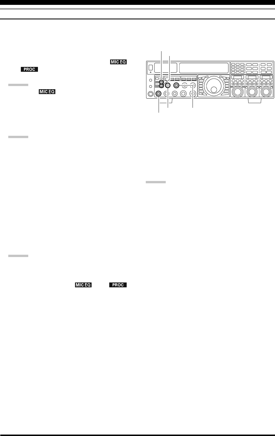
ENHANCING TRANSMIT SIGNAL QUALITY
USING THE SPEECH PROCESSOR (SSB MODE)
The Speech Processor is designed to increase “talk power” by increasing the average power output via a sophisticated
compression technique. The result is improved intelligibility when conditions are difficult.
1. Adjust the [MIC] (gain) knob for SSB use, as described
on page 70.
2. Press the [PROC] button repeatedly until the “ ”
and “ ” icons appear in the display, confirming
that the Speech Processor is engaged.
ADVICE:
A blinking “ ” icon indicates the Parametric
Microphone Equalizer menu settings have all been set
to “OFF” (“160 TAUD PE1 FRQ”, “163 TAUD PE2
FRQ”, and “166 TAUD PE3 FRQ”).
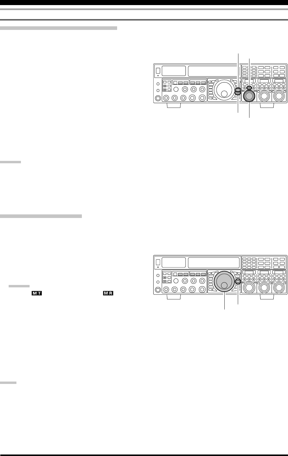
3. Set the [PROC] knob between the 9:00 to 12:00
o’clock position.
ADVICE:
The relative compression level of the Speech Proces-
sor will show for 3 seconds in the lower right corner of
the Main Display whenever the outer [PROC] knob is
turned.
Alternately, the 3-second display feature may be
changed to show in the SUB DISPLAY-
III
window
via Menu item “018 DISP INDI”. Additionally, you
may disable the 3-second display feature via Menu item
“017 DISP LVL IND” See page 122 for details.
4. Rotate the [METER] switch fully to the left, to select
“COMP” (Compression).
5. Press the PTT switch on the microphone, and speak
into the microphone in a normal voice level. Confirm
that the compression level is within the 5 dB to 10 dB
range.
ADVICE:
We recommend that you set the [PROC] knob between
9:00 to 12:00 o’clock position as described previously.
5. To switch the Speech Processor off, press the [PROC]
button repeatedly until the “ ” and “ ”
icons disappear.
[METER] Switch
[MONI] Button
[MONI] Knob
[PROC] Knob
[MIC] Button
[PROC] Button
ADVICE:
Excessive advancement of the [PROC] knob will re-
sult in a degradation of the transmitted signal-to-noise
ratio, thereby reducing intelligibility at the other end
of the circuit.
The Transmit Monitor provides a helpful way of veri-
fying proper adjustment of the compression level.
Pressing the [MONI] button then adjusting the [MONI]
knob for a comfortable listening level while you are
transmitting, allows you to hear the difference in sound
quality as you make adjustments.
The [RF PWR] knob still controls the RF power out-
put, whether or not the Speech Processor is engaged.
When the optional DMU-2000 Data Management Unit
is connected, you may observe the effect of your com-
pression level adjustments by viewing the wave-form
on the “Oscilloscope” page.
Page 77FTDX5000 OPERATING MANUAL
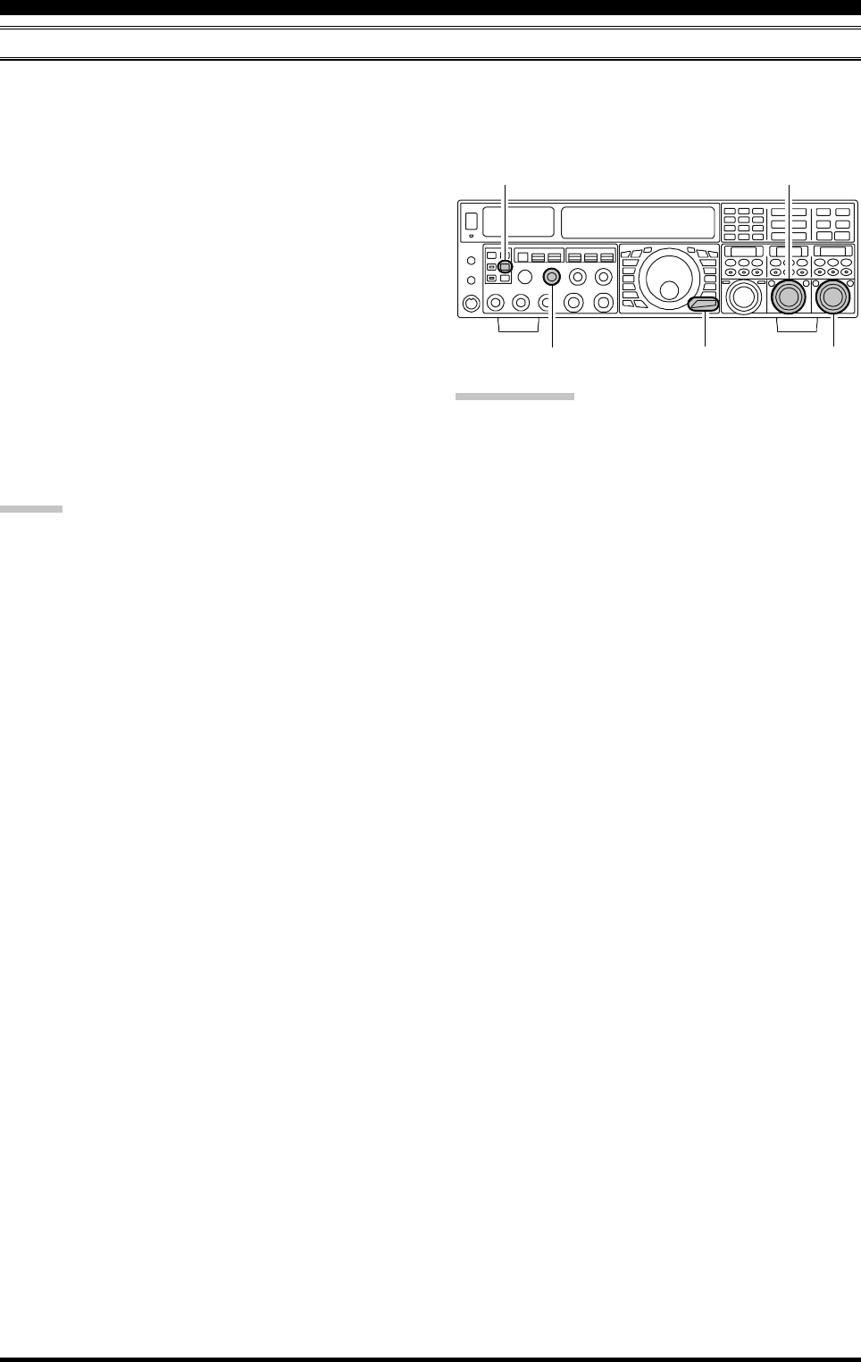
ADJUSTING THE SSB TRANSMITTED BANDWIDTH (SSB MODE)
For SSB transmission, a default bandwidth of 2.4 kHz is provided. This bandwidth provides reasonable fidelity along with
good talk power, and is typical of the bandwidth used for decades during SSB transmission. However, the bandwidth may
be varied by the operator, when preferred, to provide different levels of fidelity or increased talk power.
ENHANCING TRANSMIT SIGNAL QUALITY
Here’s how to adjust the transmitted bandwidth on SSB:
1. Press the [MENU] button briefly, to engage the Menu.
2. Rotate the (VFO-A)[SELECT] knob, and select Menu
item “104 A3J TX BPF”.
3. Rotate the (VFO-B)[SELECT] knob to select the de-
sired bandwidth. The available selections are 50-3000,
100-2900, 200-2800, 300-2700, 400-2600, and
3000WB. The default is 300-2700 Hz. A wider band-
width will provide greater fidelity, while a narrow band-
width will compress the available transmitter power
into less spectrum, resulting in more “talk power” for
DX pile-ups.
4. Press and hold in the [MENU] button for two seconds
to save the new setting and exit to normal operation.
ADVICE:
The Transmit Monitor is very helpful way of verifying
the effects on fidelity of changing the bandwidth. Press-
ing the [MONI] button then adjusting the [MONI] knob
for a comfortable listening level while you are trans-
mitting, you will be able to hear the difference in sound
quality as you make changes.
When the optional DMU-2000 Data Management Unit
is connected, you may verify the effect of your adjust-
ments of the transmitted bandwidth by observing the
Audio Scope on the “Oscilloscope” page.
QUICK POINTS:
The higher fidelity associated with wide bandwidth will
be particularly enjoyable on the low bands, during lo-
cal rag-chew QSOs.
The “3000WB” setting is a special hi-fidelity setting,
whereby the transmitted bandwidth is in excess of 3
kHz. This selection, in conjunction with judicious ad-
justment of the Parametric Microphone Equalizer (see
next chapter) can provide truly outstanding fidelity and
very natural-sounding audio.
When using the wider bandwidth selections (especially
“3000WB”), the apparent power output from the trans-
mitter may seem lower. This is because the available
power from the transmitter is being distributed over a
wider bandwidth, and the power detection circuitry
does not compensate for the effect of the bandwidth
selection (it is calibrated in the default 2.4 kHz band-
width).
(VFO-B)[SELECT] Knob
[MENU] Button
(VFO-A)[SELECT] Knob
[MONI] Button
[MONI] Knob
Page 78 FTDX5000 OPERATING MANUAL
ENHANCING TRANSMIT SIGNAL QUALITY
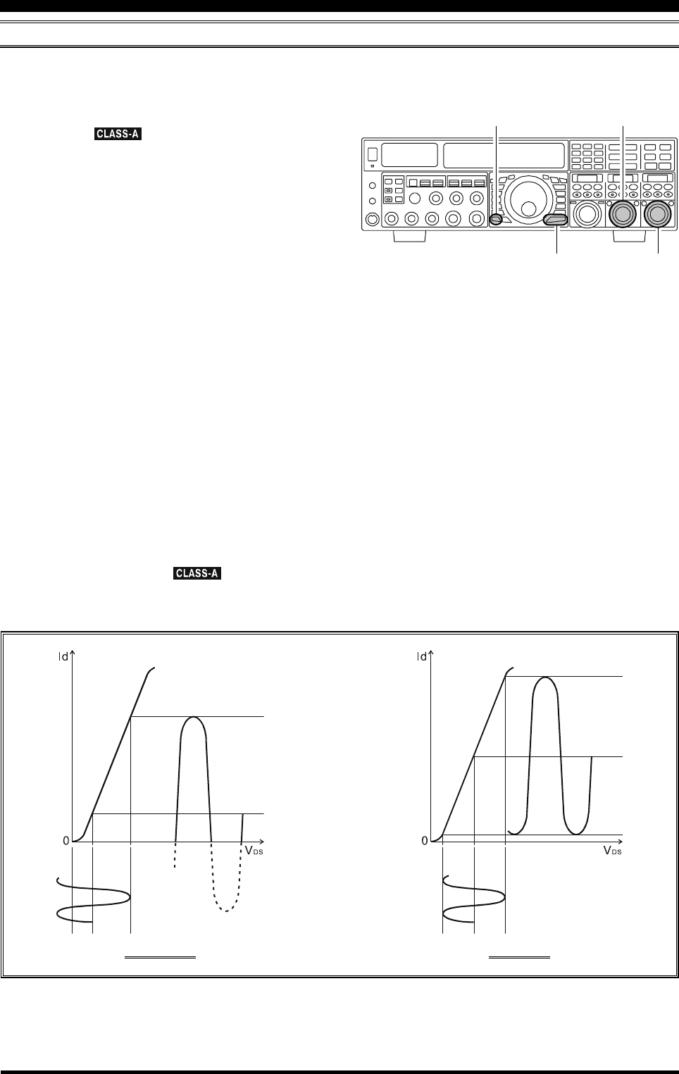
LOW- DISTORTION CLASS-A OPERATION (SSB MODE)
Class-A operation of the FTDX5000 transmitter is provided, yielding ultra-low distortion products during SSB operation.
Power output during Class-A operation is 75 Watts.
1. To engage Class-A operation, press the [CLASS-A]
button. The “ ” icon will appear in the display,
confirming that Class-A operation has been selected.
2. Engaging the “Class-A” mode actually places the trans-
ceiver in a condition whereby the Bias level may be
adjusted, via the Menu mode.
1)Press the [MENU] button briefly, to engage the
Menu.
2)Rotate the (VFO-A)[SELECT] knob, and select
Menu item “169 TGEN BIAS”.
3)Rotate the (VFO-B)[SELECT] knob to select the
desired BIAS level “1 - 100” to set the transceiver
for operation anywhere between Class-A and Class-
AB (Class-AB has lower heat dissipation but higher
distortion products).
A menu setting of “100” will place the transmitter
fully in Class-A operation. Counter-clockwise ro-
tation of the (VFO-B)[SELECT] knob will move
the transmitter toward Class-AB operation. The
menu setting “1” will place the transmitter fully in
Class-AB operation.
4)Press and hold in the [MENU] button for two sec-
onds to save the new setting and exit to normal
operation.
3. To exit from the CLASS-A mode, press the [CLASS-
A] switch once more. The “ ” icon disappears,
confirming that the CLASS-A mode has been disen-
gaged.
CLASS-AB CLASS-A
Id: Drain Current
VDS: Drain Voltage
(VFO-B)[SELECT] Knob
[MENU] Button
(VFO-A)[SELECT] Knob
[CLASS-A] Button
Page 79FTDX5000 OPERATING MANUAL
ENHANCING TRANSMIT SIGNAL QUALITY
ADVICE
During Class-A operation, 10-Amps of Bias current will be flowing, regardless of the modulation level that leads to
actual power output. Therefore, if the ambient temperature in your operation location is high, the transceiver tempera-
ture may rise as well, due to the high bias level (which must be dissipated as heat). Depending on the temperature, you
may wish to reduce the BIAS level using menu item “169 TGEN BIAS”, to reduce the amount of heat being generated.
When the optional DMU-2000 Data Management Unit and a video monitor are connected, you can monitor the heat
sink temperature on the video monitor; thus, you can always be aware of a rise in temperature during Class-A operation.
Normally, the temperature is below 80 °C. If the temperature rises to near or above this value, however, we recommend
you adjust the BIAS level toward Class-AB via menu item “169 TGEN BIAS” (decrease the numerical value to reduce
the heat being dissipated).
An innovative aspect of the “Class-A” mode is that the actual power output is always limited to 75 Watts. So even
though you might adjust the BIAS in the direction of Class-AB operation, the power output will not rise; this eliminates
the need to re-tune your linear amplifier, if used.
QUICK POINT
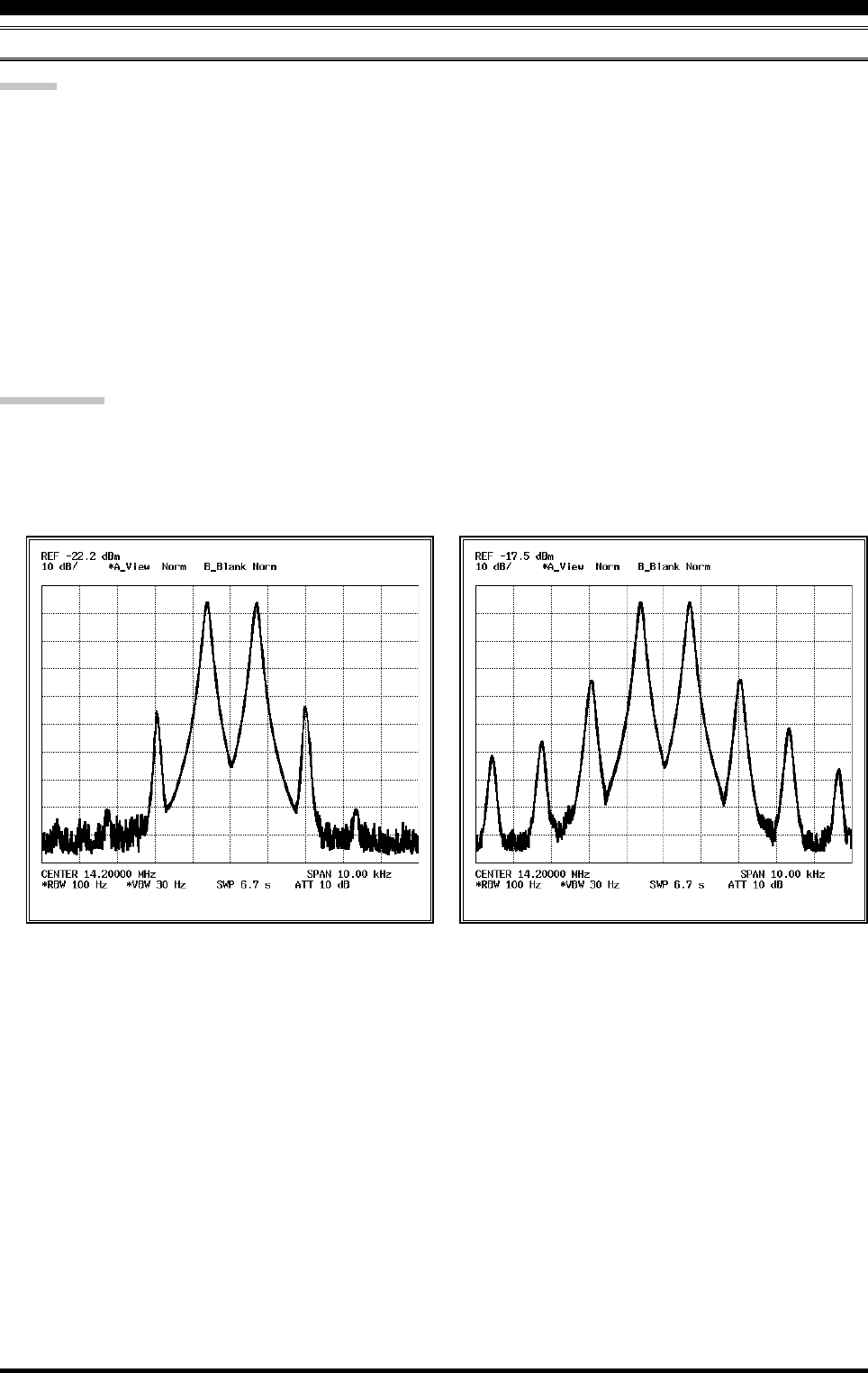
Class-A operation provides a significant improvement in transmitter distortion suppression. During Class-A operation,
the 3rd-order IMD products are typically suppressed 45 dB. The 5th- and higher-order IMD products that can cause
“splatter” and interfere with others, will typically be suppressed 70 dB or more.
If you are using a linear amplifier such as the VL-1000, the low distortion produced by the FTDX5000’s transmitter
means these intermodulation distortion products will not exist to be amplified by your linear.
LOW- DISTORTION CLASS-A OPERATION (SSB MODE)
The High-Power 200-Watt Final Amplifier Stage of the FTDX5000 utilizes a pair of ST Micro Electronics Corp. SD2931
MOSFET devices operating at 50 Volts. The push-pull configuration provides low distortion along with high power
output. The 92 mm thermostatically-controlled cooling fan directs forced air across the heat sink, when triggered by a
rise in heat sink temperature.
Class-AB 200W PEP IMDClass-A 75W PEP IMD
Page 80 FTDX5000 OPERATING MANUAL
Checking Your Recording
1. Be sure that the front panel [MOX] and [VOX] but-
tons are both “Off” (the LED imbedded in the button
must be off).
2. Press the FH-2’s [1] ~ [5] key (whichever one you just
recorded in), and you will hear the contents of the voice
memory you just recorded.
ADVICE:
You may adjust the playback level of the recording via
Menu item “020 DVS RX LVL”.
Transmitting the Recorded Message
1. Select the LSB, USB, AM, or FM mode using the front
panel [MODE] buttons.
2. Press the front panel [BK-IN] button briefly.
3. Press the FH-2’s [1] ~ [5] key, depending on which
memory register message you wish to transmit. If you
hit the key again during playback, the message will be
terminated.
ADVICE:
You may adjust the transmit (audio) level of the recording
via Menu item “021 DVS TX LVL”.
LOCK
OFFON
LOCK
OFFON
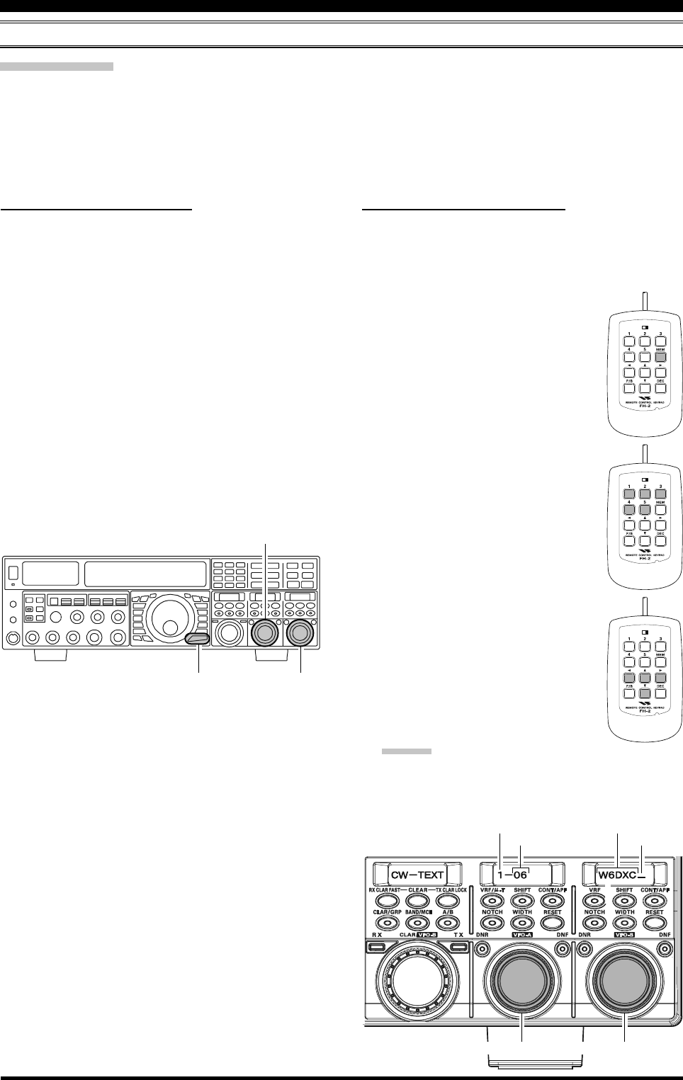
VOICE MEMORY (SSB/AM/FM MODES)
You may utilize the Voice Memory capability of the FTDX5000 by plugging in the supplied FH-2 Remote Control Keypad
into the rear panel REMOTE jack.
The Voice Memory system includes five memories capable of storing up to 20 seconds of voice audio each. The maximum
that any memory can hold is 20 seconds.
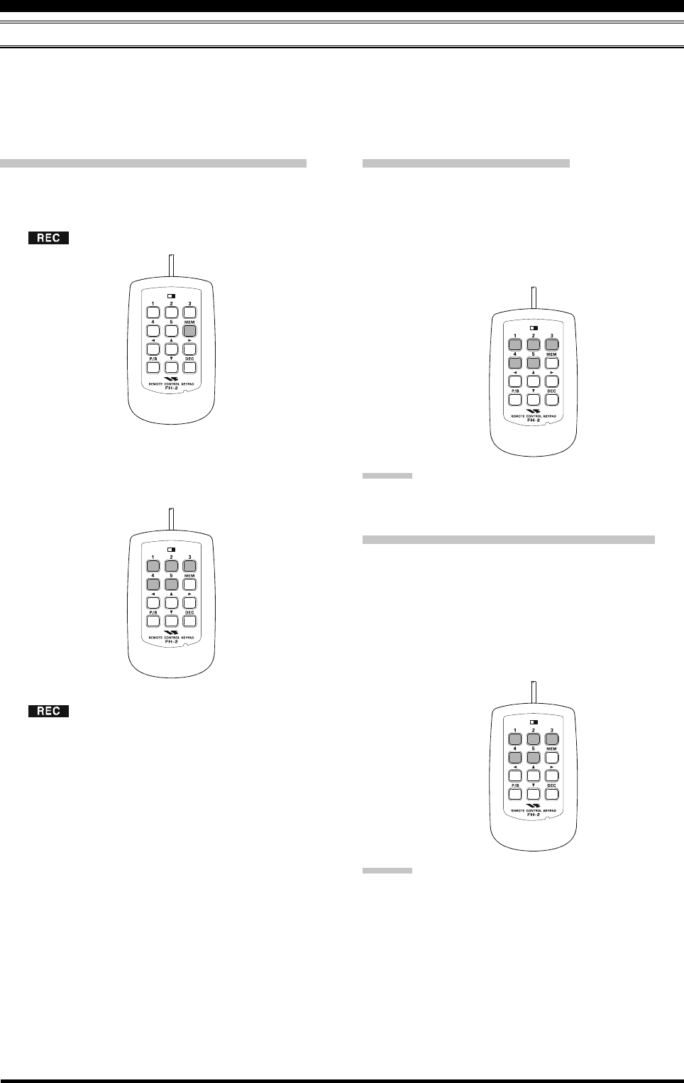
Recording Your Own Voice in Memory
1. Select the LSB, USB, AM, or FM mode using the front
panel [MODE] buttons.
2. Press the [MEM] key on the FH-2 briefly. A blinking
“” icon will appear in the display
3. Press any of the FH-2’s keys numbered [1] through
[5] to select that memory storage register. If you do
not press the PTT key (see next step) within five sec-
onds, the memory storage process will be cancelled.
4. Press the microphone’s PTT switch briefly, the
“” icon will glow steadily, and recording will
begin.
5. Speak into the microphone in a normal voice level to
record the message (such as “CQ DX, CQ DX, this is
W 6 Delta X-Ray Charlie, W 6 Delta X-Ray Charlie,
Over”). Remember that the time limit for recording
any message is 20 seconds.
6. Press the FH-2’s [MEM] key to terminate the message
storage process.
TRANSMITTER CONVENIENCE FEATURES
LOCK
OFFON
LOCK
OFFON
Page 81FTDX5000 OPERATING MANUAL
VOX (AUTOMATIC TX/RX SWITCHING USING VOICE CONTROL: SSB/AM/FM MODES)
Instead of using the microphone’s PTT switch or the front panel [MOX] switch to activate the transmitter, the VOX (Voice
Operated TX/RX Control) system provides hands-free, automatic activation of the transmitter, based on voice input into
the microphone. Setup of the VOX system takes only a few seconds.
1. Adjust the [MIC] (gain) knob for SSB use, as described
on page 70.
2. Set the [VOX] and [DELAY] knobs fully counter-clock-
wise (to the left).
3. Press the [VOX] button briefly, to engage VOX opera-
tion. The [VOX] button will glow red.
4. Speak into the microphone in a normal voice level,
and rotate the [VOX] knob clockwise (to the right) until
the point where your voice input activates the trans-
mitter.
ADVICE:
Do not advance the setting of the [VOX] knob too far,
as this will make the transmitter respond to minor back-
ground noises in your station.
5. Now stop speaking, and note the amount of time it takes
for the receiver to recover. If the hang time is too long
or too short; rotate the [DELAY] knob, while speaking
briefly into the microphone, and then pausing, to set
the desired hang time. Clockwise rotation of the [DE-
LAY] knob will increase the hang time.
ADVICE:
The hang time of the VOX circuit will show for 3 sec-
onds in the lower right corner of the Main Display
whenever the outer [DELAY] knob is turned.
Alternately, the 3-second display feature may be
changed to show in the SUB DISPLAY-
III
window
via Menu item “018 DISP INDI”. Additionally, you
may disable the 3-second display feature via Menu item
“017 DISP LVL IND” See page 122 for details.
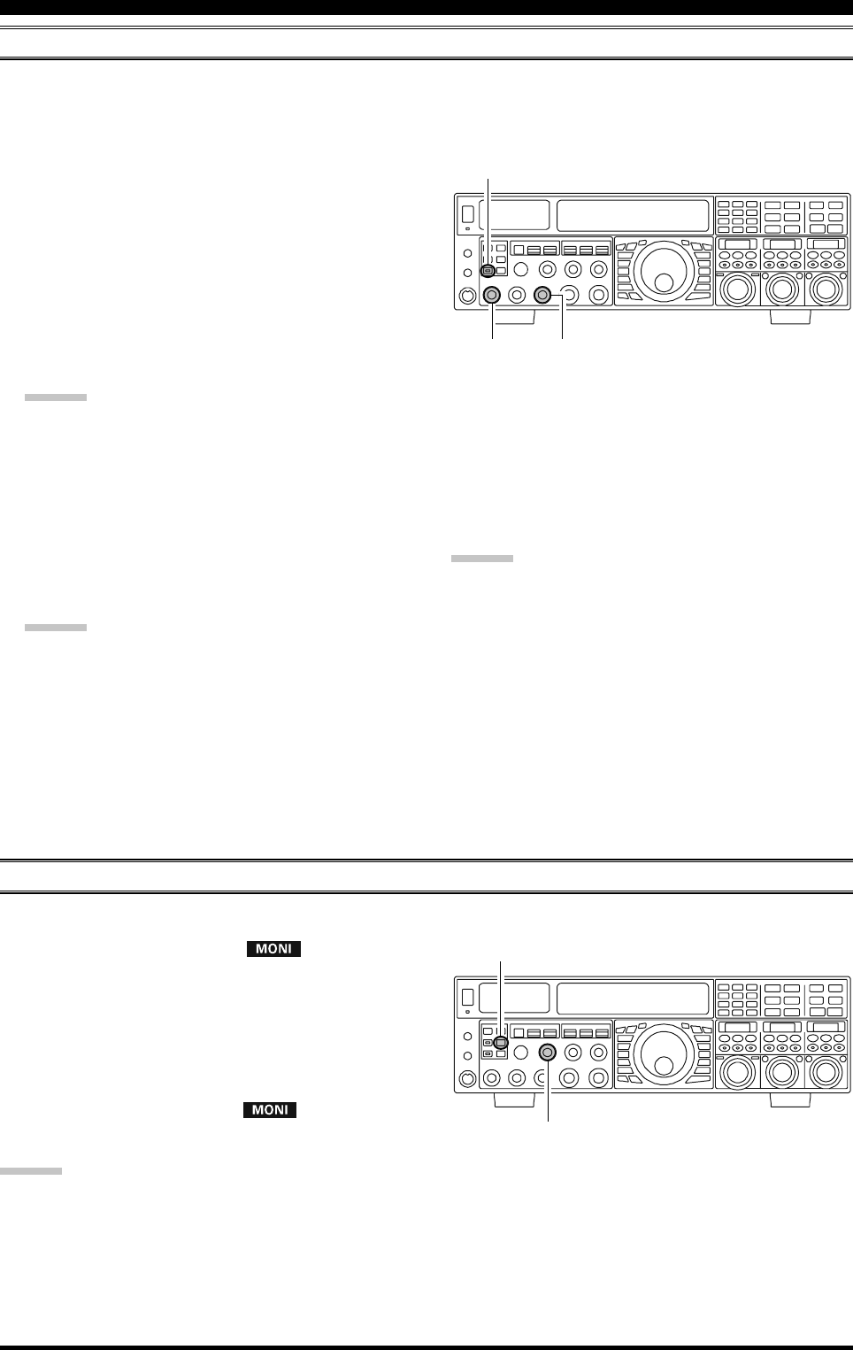
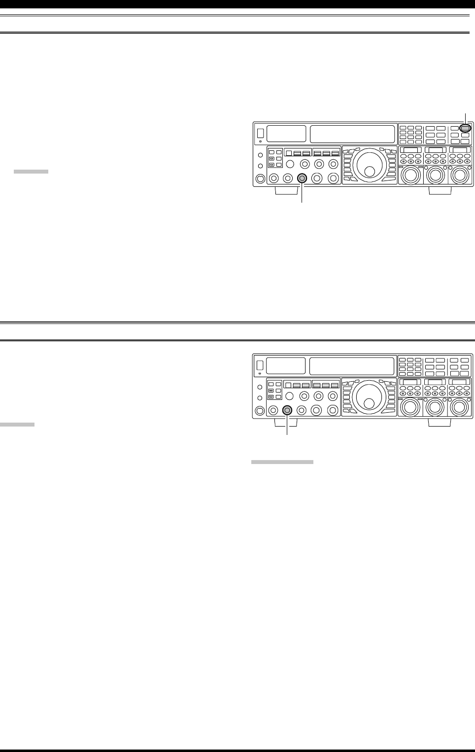
MONITOR (SSB/AM/FM MODES)
You may listen to the quality of your transmitted signal using the Monitor feature.
1. Press the [MONI] button. The “ ” icon will ap-
pear in the display, indicating that the Monitor is turned
on.
2. During transmission, rotate the [MONI] knob to ad-
just the audio level from the Monitor. Clockwise rota-
tion of this knob will increase the volume level.
3. To switch the Monitor off again, press the [MONI]
button briefly once more. The “ ” icon will turn
off, confirming that the Monitor is now disengaged.
TRANSMITTER CONVENIENCE FEATURES
6. To exit from VOX operation, press the [VOX] button
once more. We recommend doing this if you are going
to leave your station, to prevent inadvertent activation
of the VOX system by a ringing nearby telephone,
speaker audio from a TV, etc.
ADVICE:
The Anti-Trip setting sets the negative feedback of re-
ceiver audio to the microphone, to prevent receiver
audio from activating the transmitter (via the micro-
phone) can be adjusts via Menu item “175 TGEN
ANTI VOX”.
VOX operation may be engaged on voice modes (SSB/
AM/FM) and on AFSK-based data modes. Use Menu
item “174 TGEN VOX SEL” (the selections are
“MIC” and “DATA”).
ADVICE:
If you are using the speaker for monitoring, instead of headphones, excessive advancement of the [MONI] knob can
cause feedback to occur. Additionally, this feedback can cause the VOX system to hang up in a loop, making it impos-
sible to return to receive. Therefore, we recommend the use of headphones, if at all possible, or the minimum usable
setting of the [MONI] knob, if the speaker must be used.
Because the monitor feature utilizes a sampling of the transmitter’s IF signal, it can be very useful for checking the
adjustment of the Speech Processor or Parametric Equalizer on SSB, and for checking the general signal quality on AM
and FM.
[VOX] Button
[VOX] Knob
[DELAY] Knob
[MIC] Knob
[MONI] Button
[MONI] Knob
Page 82 FTDX5000 OPERATING MANUAL
TRANSMITTER CONVENIENCE FEATURES
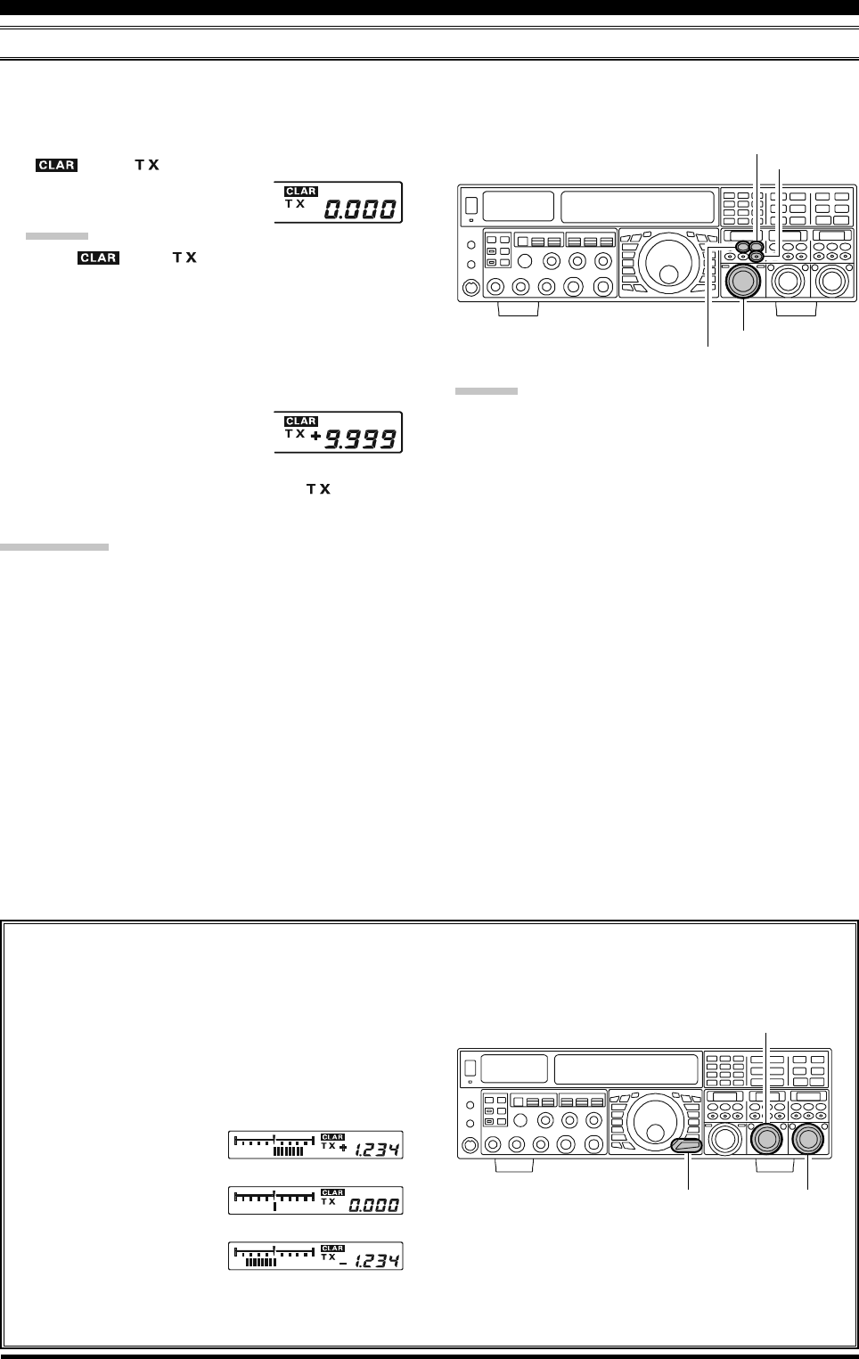
SPLIT OPERATION USING THE TX CLARIFIER (VFO-A OPERATION)
For split TX/RX operation in “casual” pile-ups, where the split is less than 10 kHz, the TX Clarifier (Offset Tuning) feature
may be utilized.
1. Press the [TX CLAR/LOCK] button briefly. The
“” and “ ” icon will appear in the display,
and the programmed offset will be
applied to the receive frequency.
ADVICE:
If the “ ” and “ ” icon does not appear, check
to see if the LED imbedded in the [A/B] button glows
orange. If so, pressing the [A/B] button briefly, will
cause the [A/B] button to go out. Now, press the [TX
CLAR/LOCK] button briefly, to begin clarifier op-
eration.
2. Rotate the [CLAR(VFO-B)] knob to set the desired
transmitter offset. A maximum
split of ±9.999 kHz may be set.
3. To exit from TX Clarifier operation, press the [TX
CLAR/LOCK] button once more. The “ ” icon will
disappear from the display.
QUICK POINT:
When attempting to work a DX station on CW, in a split-
frequency pile-up, remember that a large number of other
stations may also be using Yaesu transceivers with capa-
bilities similar to your FTDX5000. On the DX side of the
pile-up, everyone calling precisely on the same CW fre-
quency will sound like a single tone! So you may have
more success if you use the RX Clarifier to find a hole in
the pile-up, instead of trying to zero-beat the last station
worked by the DX station.
Clarifier Offset Bar Indicator
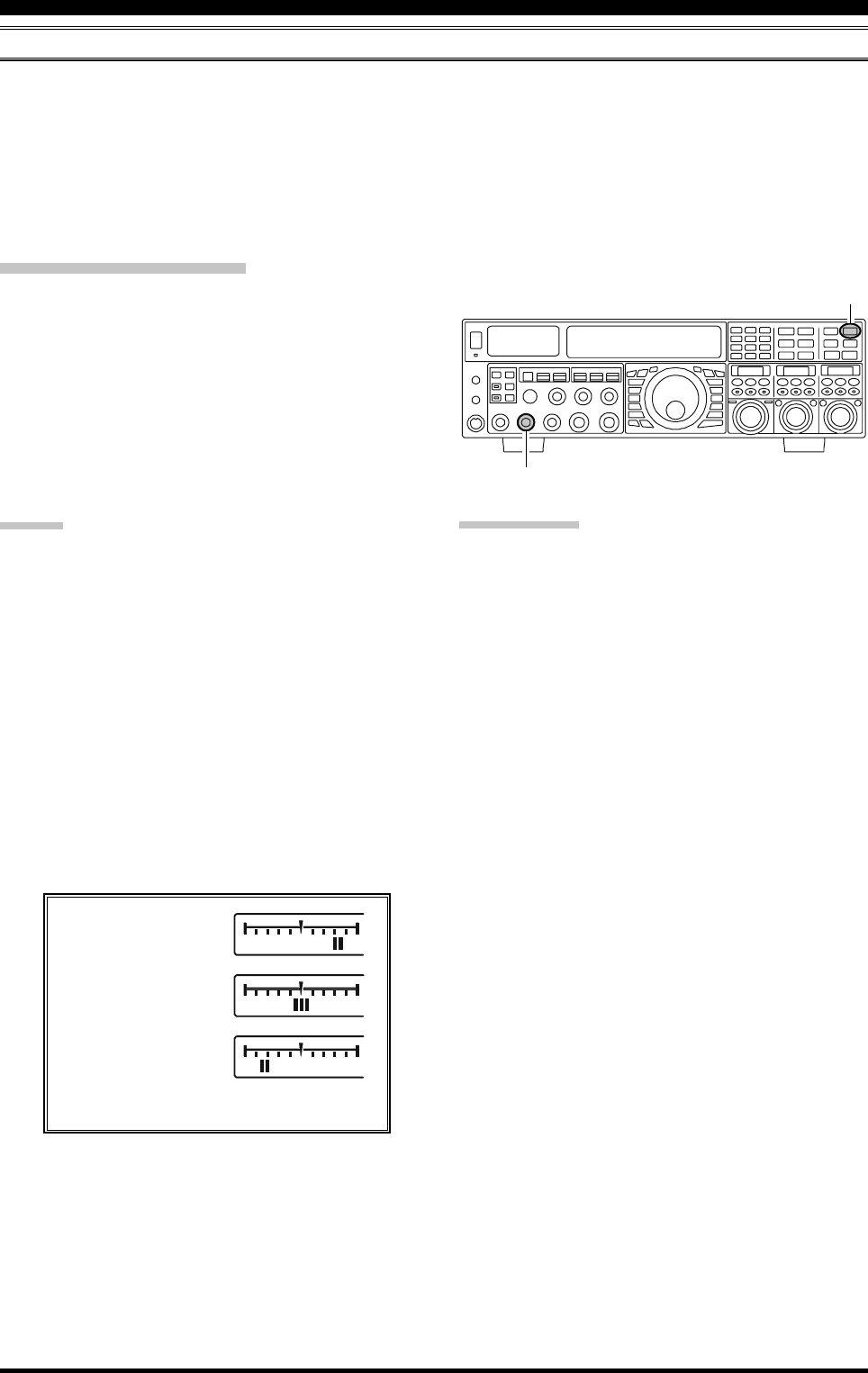
A visual depiction of the relative offset of the Clarifier may be displayed, using the Bar Indicator.
1. Press the [MENU] button briefly, to enter the Menu
mode.
2. Rotate the (VFO-A)[SELECT] knob to select
Menu item “012 DISP BAR SEL”.
3. Rotate the (VFO-B)[SELECT] knob to select
“CLAR (Clarifier)” (re-
placing the default “CW
TUNE (CW TUNING)”
selection).
4. Press and hold in the
[MENU] button for two
seconds to save the new
setting and exit to nor-
mal operation.
ADVICE:
The frequency step of the TX clarifier depends on the
Main Tuning Dial knob.
To listen to the pile-up calling the DX station, to find
the station currently being worked, you may press the
[RX CLAR/FAST] button. Once you have zeroed in
on the station calling the DX (use the SPOT function
on CW for precise alignment of your frequency), you
may then briefly press the [RX CLAR/FAST] button
again to cancel the RX Clarifier, and return to recep-
tion on the DX station’s frequency.
Just as with receiver clarifier operation, the amount of
offset from the original VFO frequency will appear in
the small display window.
As with receiver clarifier operation, when you turn the
TX clarifier off the last-used offset is not lost, and will
be available if you turn the TX Clarifier back on. To
clear the Clarifier offset, briefly press the [CLEAR]
button.
[CLAR(VFO-B)] Knob
[CLEAR] Button
[TX CLAR/LOCK] Button
[A/B] Button
[Plus (+) Offset]
[Zero Offset]
(Minus (–) Offset)
(VFO-B)[SELECT] Knob
[MENU] Button
(VFO-A)[SELECT] Knob
Page 83FTDX5000 OPERATING MANUAL
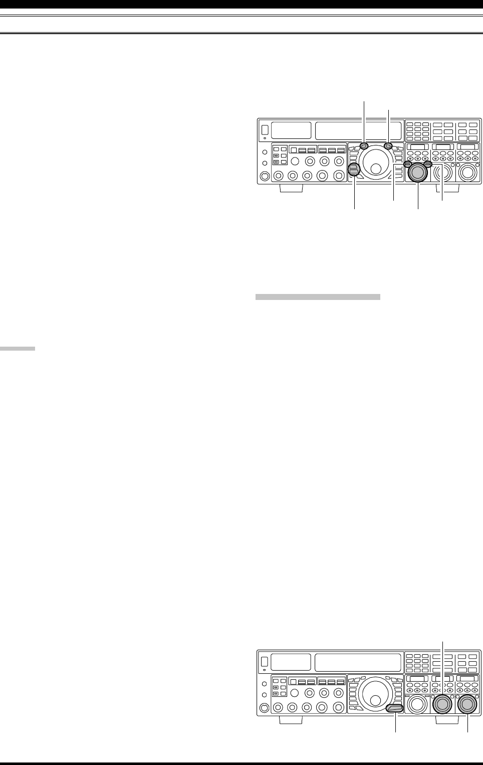
SPLIT-FREQUENCY OPERATION
A powerful capability of the FTDX5000 is its flexibility in Split Frequency operation, using the Main (VFO-A) and Sub
(VFO-B) frequency registers. This makes the FTDX5000 especially useful for high-level DX-pedition use, as the Split
operation capability is very advanced and easy to use.
TRANSMITTER CONVENIENCE FEATURES
1. Set the VFO-A frequency as desired.
2. Set the VFO-B frequency.
3. Now press the [SPLIT] button briefly. The front panel
switch/LEDs will look like this:
(VFO-A)[RX] button: LED glows green
(VFO-A)[TX] button: LED off
(VFO-B)[RX] button: LED off
(VFO-B)[TX] button: LED glows red
3. During Split operation, the VFO-A register will be used
for reception, while the VFO-B register will be used
for transmission. If you press the [SPLIT] button once
more, Split operation will be cancelled.
(VFO-A)[RX] button: LED glows green
(VFO-A)[TX] button: LED glows red
(VFO-B)[RX] button: LED off
(VFO-B)[TX] button: LED off
4. You may also press the (VFO-A)[TX] button to return
transmit frequency control to the VFO-A side, thereby
canceling split operation.
ADVICE:
During normal (non-split) VFO-A operation, you may
simply press the (VFO-B)[TX] button (located above
and to the right of the [CLAR(VFO-B)] knob) to en-
gage Split operation. The (VFO-B)[TX] button will
glow red when you press the button.
During Split operation, pressing the [A
B] button will
reverse the contents of VFO-A and VFO-B. Press the
[A
B] button once more, to return to the original fre-
quency alignment.
During Split operation, if you press the (VFO-B)[RX]
button above and to the right of the [CLAR(VFO-B)]
knob, you will engage Dual Receive operation. Now
you can listen to both sides of the DX pile-up, and
transmit on the VFO-B frequency. This is very useful
to determine the timing of your calls, while also moni-
toring both sides of the pile-up.
During Split operation, you may also listen to the TX
frequency temporarily, by pressing the [TXW] button
(just below the [SPLIT] button).
It is possible to set different operating modes (for ex-
ample, LSB and USB) on the two VFOs used during
Split operation.
During Split operation, it is also possible to set VFO-
A and VFO-B to different amateur bands. But, remem-
ber that Dual Reception must be within the same band.
VFO Tracking Feature
In the default setting, the VFO-A frequency and VFO-B
frequency are changed individually using the Main Tun-
ing Dial knob and the [CLAR(VFO-B)] knob.
If you want to tune the VFO-A frequency and VFO-B fre-
quency together, the VFO Tracking feature is very useful.
Here is the procedure for activating the VFO Tracking fea-
ture:
1. Press the [MENU] button briefly, to engage the Menu
mode.
2. Rotate the (VFO-A)[SELECT] knob to select Menu
item “038 GENE TRACK”.
3. Rotate the (VFO-B)[SELECT] knob to select the de-
sired Tracking mode.
OFF: Disables the VFO Tracking feature.
BAND: When you change the band on the VFO-A side,
the VFO-B band will automatically change to
be the same band as VFO-A.
FREQ: This function is similar to the “BAND” setting,
and will additionally “lock” VFO-A and VFO-
B together. Turning the Main Dial will tune both
VFO-A and VFO-B simultaneously.
4. Press and hold in the [MENU] button for two seconds
to lock in the new configuration and exit to normal
operation.
(VFO-B)[SELECT] Knob
[MENU] Button
(VFO-A)[SELECT] Knob
[CLAR(VFO-B)] Knob
(VFO-B)[TX] Button
(VFO-B)[RX] Button
[SPLIT] Button
[TXW] Button
(VFO-A)[TX] Button
(VFO-A)[RX] Button
Page 84 FTDX5000 OPERATING MANUAL
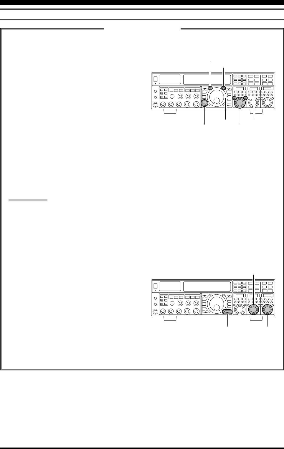
TRANSMITTER CONVENIENCE FEATURES
SPLIT-FREQUENCY OPERATION
1. Start with regular transceiver operation on the VFO-
A.
(VFO-A)[RX] button: LED glows green
(VFO-A)[TX] button: LED glows red
(VFO-B)[RX] button: LED off
(VFO-B)[TX] button: LED off
2. Press and hold in the [SPLIT] button for two sec-
onds to engage the Quick Split feature, and apply a
frequency 5 kHz above the VFO-A frequency to
the VFO-B frequency register.
The VFO configuration will then be:
(VFO-A)[RX] button: LED glows green
(VFO-A)[TX] button: LED off
(VFO-B)[RX] button: LED off
(VFO-B)[TX] button: LED glows red
3. Press and hold in the [SPLIT] switch for two sec-
onds to increment the VFO-B frequency another
+5 kHz.
QUICK POINTS:
The operating mode applied to the VFO-B register
will be the same as that in use on the VFO-A regis-
ter.
The offset of the VFO-B from the VFO-A is pro-
grammed via the Menu, and is set to +5 kHz at the
factory. Other offsets may be selected using the fol-
lowing procedure:
1. Press the [MENU] button briefly, to enter the Menu
mode.
2. Rotate the (VFO-A)[SELECT] knob to select
Menu item “037 GENE Q SPLIT”.
3. Rotate the (VFO-B)[SELECT] knob to select the
desired offset.
The available selections are –20kHz ~ +20kHz (fac-
tory default: +5 kHz).
4. When you have completed all adjustments, press
and hold in the [MENU] button for two seconds to
save the new setting and exit to normal operation.
If you only press the [MENU] button briefly to exit,
any changes you performed will not be stored.
Quick Split Operation
The Quick Split feature allows you to set a one-touch offset of +5 kHz, to be applied to the transmit frequency on
VFO-B, as compared to the VFO-A frequency.
[CLAR(VFO-B)] Knob
(VFO-B)[TX] Button
(VFO-B)[RX] Button
[SPLIT] Button
[TXW] Button
(VFO-A)[TX] Button
(VFO-A)[RX] Button
(VFO-B)[SELECT] Knob
[MENU] Button
(VFO-A)[SELECT] Knob

Page 85FTDX5000 OPERATING MANUAL
NOTE
Page 86 FTDX5000 OPERATING MANUAL
The powerful CW operating capabilities of the FTDX5000 include operation using both an electronic keyer paddle and a
“straight key” or emulation thereof, as is provided by a computer-based keying device.
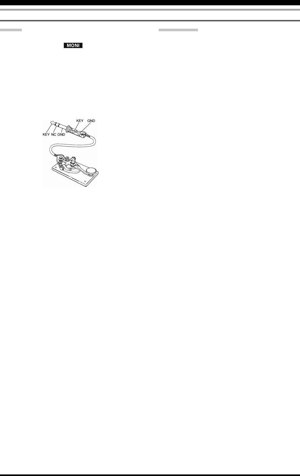
SETUP FOR STRAIGHT KEY (AND STRAIGHT KEY EMULATION) OPERATION
Before starting, connect your key line(s) to the front and/or rear panel KEY jack(s). Be sure the [KEYER] button on the
front panel is turned off for now.
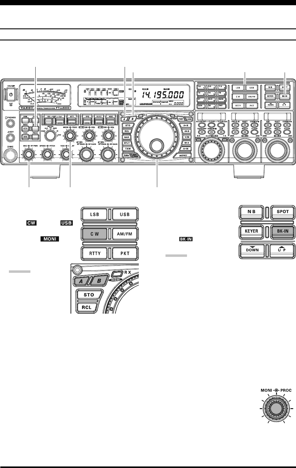
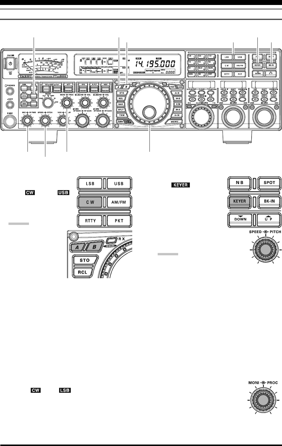
CW MODE OPERATION
1. Press the [CW] mode button
to engage CW operation.
The “ ” and “ ”
icons will appear in the dis-
play. The “ ” icon
will also appear in the dis-
play; and the CW monitor is
activated.
ADVICE:
The operating mode
is selected using the
[MODE] button.
The VFO, to which
the selection is ap-
plied, is selected by the [A] or [B] button (located
to the upper left of the Main Tuning Dial knob).
Usually, the [A] button glows red, signifying VFO-
A is being adjusted. Alternately, pressing the [B]
button will cause its indicator to glows orange, sig-
nifying VFO-B adjustment. Therefore, press the [A]
or [B] button to select the desired VFO, then press
the [CW] button to select the CW mode.
After initially selecting CW, if you press the [CW]
button once more, you will engage the “CW Re-
verse” mode (see page 92). Normally, the upper
sideband (USB) is used in conjunction with CW.
In reverse CW the lower sideband (LSB) is used.
2. Rotate the Main Tuning Dial knob to select the desired
operating frequency.
3. Press the [BK-IN] button
briefly, to engage automatic
activation of the transmitter
when you close the CW key.
The “ ” icon will appear
in the display.
ADVICE:
When you close your CW
key, the transmitter will automatically be activated,
and the CW carrier will be transmitted. When you
release the key, transmission will cease after a brief
delay; the delay time is user-programmable, per the
discussion on page 93.
As shipped from the factory, the FTDX5000 TX/
RX system for CW is configured for “Semi-break-
in” operation. However, using Menu item “063 A1A
BK-IN”, you may change this setup for full break-
in (QSK) operation, whereby the switching is quick
enough to hear incoming signals in the spaces be-
tween the dots and dashes of your transmission. This
may prove very useful during contest and traffic-
handling operations.
4. Operation using your CW key may now proceed.
A CW sidetone sounds from a speaker
in accordance with your keying. Ad-
just the [MONI] knob for a comfort-
able listening level of the CW
sidetone.
Main Tuning Dial knob
[BK-IN] Button
[B] Button
[MONI] Button
[MODE] Buttons
[A] Button
[RF PWR] Knob [MONI] Knob
Page 87FTDX5000 OPERATING MANUAL
ADVICE:
You may disable the CW sidetone by pressing the
[MONI] button. The “ ” icon will turn off, con-
firming that the Monitor is now disengaged.
If you set the [BK-IN] button to off, you may practice
your sending without having the signal go out over the
air (sidetone only).
If you reduce power using the [RF PWR] knob, the
ALC meter reading will increase. This is normal and
does not indicate any problem whatsoever (because in-
creased ALC voltage is being used to lower the power).
SETUP FOR STRAIGHT KEY (AND STRAIGHT KEY EMULATION) OPERATION
TERMINOLOGY:
Semi-break-in
This is a pseudo- “VOX” mode used on CW, where
the closure of the CW key will engage the transmitter.
Releasing the key, will allow the receiver to recover
after a short delay. No signals will be heard between
the spaces between dots and dashes (unless the send-
ing speed is extremely slow).
Full break-in
Full break-in (Also known as “Full QSK”) involves
very fast switching between transmit and receive, such
that incoming signals may be heard between the dots
and dashes as you send them. This allows you to hear a
station that suddenly starts transmitting on your fre-
quency, while you are in the midst of sending a mes-
sage.
Page 88 FTDX5000 OPERATING MANUAL
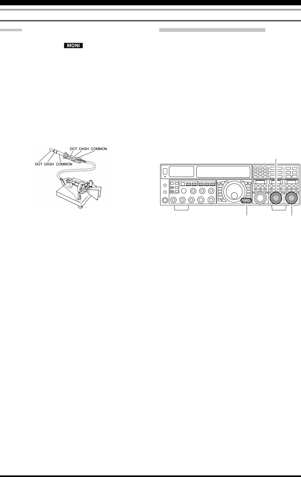
USING THE BUILT-IN ELECTRONIC KEYER
Connect the cable from your keyer paddle to the front or rear panel KEY jack.
1. Press the [CW] mode button
to engage CW operation.
The “ ” and “ ”
icons will appear in the dis-
play, and the CW monitor
will be activated.
ADVICE:
The operating mode
is selected using the
[MODE] button.
The (A or B) VFO to
which the selection
is applied, is se-
lected by the [A] or
[B] button, located to the upper left of the Main
Tuning Dial knob. Usually, the [A] button glows
red, signifying VFO-A is being adjusted. Alter-
nately, pressing the [B] button will cause its indi-
cator to glow orange, signifying VFO-B adjustment.
Therefore, press the [A] or [B] button to select the
desired VFO, then press the [CW] button to select
the CW mode.
After initially selecting CW, If you press the [CW]
button once more you will engage the “CW Re-
verse” mode (see page 92), whereby the “oppo-
site” sideband injection is used. Normally, the up-
per sideband (USB) is used in conjunction with CW.
In reverse CW the lower sideband (LSB) is used.
The “ ” and “ ” icons will appear if you
select CW Reverse.
2. Rotate the Main Tuning Dial knob to select the desired
operating frequency.
3. Press the [KEYER] button.
The “ ” icon will ap-
pear in the display, confirm-
ing that the built-in Elec-
tronic Keyer is now active.
4. Rotate the [SPEED] knob to
set the desired sending speed
(4 ~ 60 wpm). Clockwise ro-
tation of the [SPEED] knob will in-
crease the keying speed.
ADVICE:
The keying speed will show for 3
seconds in the lower right corner of the Main Dis-
play whenever the outer [SPEED] knob is turned.
Alternately, the 3-second display feature may be
changed to show in the SUB DISPLAY-
III
win-
dow via Menu item “018 DISP INDI”. Addition-
ally, you may disable the 3-second display feature
via Menu item “017 DISP LVL IND” See page
122 for details.
When you press either the “Dot” or “Dash” side of
your paddle, the transmitter will automatically be
activated.
5. If you press the [BK-IN] button briefly, “semi-break-
in” operation (discussed previously) will be engaged.
6. CW operation utilizing your paddle may now com-
mence.
A CW sidetone sounds from a speaker
in accordance with your keying. Ad-
just the [MONI] knob for a comfort-
able listening level of the CW
sidetone.
Main Tuning Dial knob
[BK-IN] Button
[B] Button
[MONI] Button
[MODE] Buttons
[MONI] Knob
[A] Button
[RF PWR] Knob
[KEYER] Button
[SPEED] Knob
CW MODE OPERATION
Page 89FTDX5000 OPERATING MANUAL
ADVICE:
You may disable the CW sidetone by pressing the
[MONI] button. The “ ” icon will turn off, con-
firming that the Monitor is now disengaged.
When you utilize your keyer paddle, the transmitter
will automatically be activated, and the CW charac-
ters (or a string of dots and dashes) will be transmit-
ted. When you release the keyer paddle contacts, trans-
mission will cease after a brief delay. The delay time is
user-programmable, per the discussion on page 93.
If you reduce power using the [RF PWR] knob, the
ALC meter reading will increase. This is normal and
does not indicate any problem whatsoever (because in-
creased ALC voltage is being used to lower the power).
USING THE BUILT-IN ELECTRONIC KEYER
CW MODE OPERATION
Full Break-in (QSK) Operation
As shipped from the factory, the FTDX5000 TX/RX sys-
tem for CW is configured for “Semi-break-in” operation.
However, using Menu item “063 A1A BK-IN”, you may
change this setup for full break-in (QSK) operation,
whereby the switching is quick enough to hear incoming
signals in the spaces between the dots and dashes of your
transmission.
1. Press the [MENU] button to enter the Menu mode.
2. Rotate the (VFO-A)[SELECT] knob to select Menu
item “063 A1A BK-IN”.
3. Rotate the (VFO-B)[SELECT] knob to set this Menu
item to “FULL”.
4. Press and hold in the [MENU] button for two seconds
to save the new setting and exit.
(VFO-B)[SELECT] Knob
[MENU] Button
(VFO-A)[SELECT] Knob
Page 90 FTDX5000 OPERATING MANUAL
A number of interesting and useful features are available during Electronic Keyer operation.
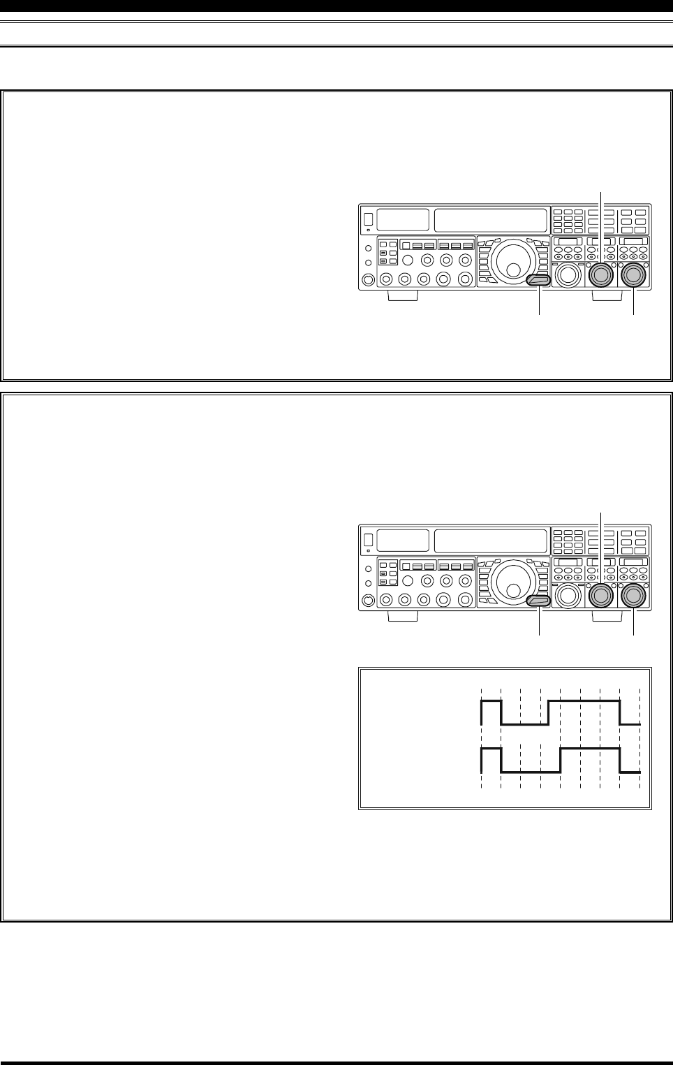
SETTING THE KEYER WEIGHT (DOT/SPACE:DASH) RATIO
The Menu may be used to adjust the Weight for the built-in Electronic Keyer. The default weighting is 3:1 (a dash is
three times longer than a dot or space).
USING THE BUILT-IN ELECTRONIC KEYER
CW MODE OPERATION
1. Press the [MENU] button briefly, to enter the Menu
mode.
2. Rotate the (VFO-A)[SELECT] knob to select
Menu item “065 A1A WEIGHT”.
3. Rotate the (VFO-B)[SELECT] knob to set the
weight to the desired value. The available adjust-
ment range is for a Dot/Space:Dash ratio of “2.5”
~ “4.5” (default value: “3.0”).
4. When you are finished, press and hold in the
[MENU] button for two seconds to save the new
setting and exit to normal operation.
SELECTING THE KEYER OPERATING MODE
The configuration of the Electronic Keyer may be customized independently for the front and rear KEY jacks of the
FTDX5000. This permits utilization of Automatic Character Spacing (ACS), if desired, as well as the use of the
electronic keyer via the front jack and a straight key or computer-driven keying line via the rear panel.
1. Press the [MENU] button briefly, to enter the Menu
mode.
2. Rotate the (VFO-A)[SELECT] knob to select
Menu item “057 A1A F-TYPE” (for the front KEY
jack) or “059 A1A R-TYPE” (for the rear-panel
KEY jack).
3. Rotate the (VFO-B)[SELECT] knob to set the
keyer to the desired mode. The available selections
are:
OFF: The built-in Electronic Keyer is turned off
(“straight key” mode).
BUG: Dots will be generated automatically by
the keyer, but dashes must be sent manu-
ally.
ELEKEY: Both dots and dashes will be generated
automatically when you use your paddle.
ACS: Same as “ELEKEY” except that the spac-
ing between characters is precisely set by
the keyer to be the same length as a dash
(three dots in length)
4. When you are finished, press and hold in the
[MENU] button for two seconds to save the new
setting and exit to normal operation.
Inter-character
spacing to short
Morse
“E” & “T”
Morse
“E” & “T”
ACS “ON”
ACS “OFF”
(VFO-B)[SELECT] Knob
[MENU] Button
(VFO-A)[SELECT] Knob
(VFO-B)[SELECT] Knob
[MENU] Button
(VFO-A)[SELECT] Knob
Page 91FTDX5000 OPERATING MANUAL
CW CONVENIENCE FEATURES
CW SPOTTING (ZERO-BEATING)
“Spotting” (zeroing in on another CW station) is a handy technique for ensuring that you and the other station are precisely
on the same frequency.
For everyday operation, the (CW) [PITCH] knob allows you to set the center of the receiver passband, as well as the offset
pitch of your CW carrier signal, to the tone pitch you prefer to listen to.
The Tuning Offset Indicator in the display may also be moved so you can adjust your receiver frequency to center the
incoming station on the pitch corresponding to that of your transmitted signal.
Using the SPOT System
While pressing the front panel [SPOT] button, the spot
tone will be heard in the speaker, and the spot tone fre-
quency will show in the lower right corner of the Main
Display. This tone corresponds to the pitch of your trans-
mitted signal, and if you adjust the receiver frequency to
match the pitch of the received CW signal to that of the
spot tone, your transmitted signal will be precisely matched
to that of the other station.
Release the [SPOT] button to turn the spot tone off.
ADVICE:
In a tough DX pile-up, you may actually want to use
the SPOT system to find a “gap” in the spread of call-
ing stations, instead of zeroing in precisely on the last
station being worked by the DX station. From the DX
side, if a dozen or more operators (also using Yaesu’s
SPOT system) all call precisely on the same frequency,
their dots and dashes merge into a single, long tone
that the DX station cannot decipher. In such situations,
calling slightly higher or lower may get your call
through.
The Tuning Offset Indicator in the display may be uti-
lized for CW frequency adjustment, as well. Its con-
figuration is set via Menu item “012 DISP BAR SEL”
at the factory, and the Tuning Offset Indicator is al-
ready set to the “CW TUNE” selection.
QUICK POINTS:
The CW spotting process utilizes the spot tone or the
Tuning Offset Indicator, with the actual offset pitch
being set by the [PITCH] knob on the front panel. The
offset pitch may be set to any frequency between 300
Hz and 1050 Hz, in 50 Hz steps, and you can either
match tones audibly (using the [SPOT] button) or align
the receiver frequency so that the central red bar on
the Tuning Offset Indicator lights up. Note that there
are 21 “dots” on the Tuning Offset Indicator, and de-
pending on the resolution selected, the incoming CW
signal may fall outside the visible range of the bar in-
dicator, if you are not reasonably close to the proper
alignment of tones.
The displayed frequency on CW, normally reflects the
“zero beat” frequency of your offset carrier. That is, if
you were to listen on USB on 14.100.70 MHz to a
signal with a 700 Hz offset, the “zero beat” frequency
of that CW carrier would be 14.000.70 MHz. The lat-
ter frequency is what the FTDX5000 displays, by de-
fault. However, you can change the display to be iden-
tical to what you would see on SSB by using Menu
item “066 A1A FRQ DISP” and setting it to “FREQ”
instead of its default “PITCH” setting.
[SPOT] Button
[PICTH] Knob
Retune:
Shift to Higher Frequency
: When the CW reversefeature is activated, the indica-
tor of the Tuning Offset Indicator will also be reversed.
Zero-In
Retune:
Shift to Lower Frequency
Page 92 FTDX5000 OPERATING MANUAL
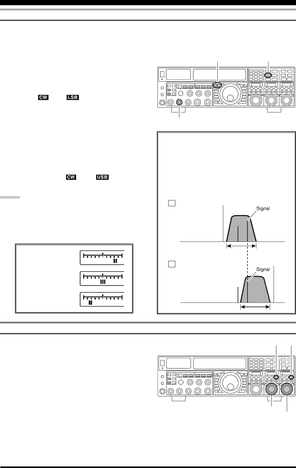
USING CW REVERSE
If you experience a difficult interference situation, where an interfering station cannot readily be eliminated, you may wish
to try receiving using the opposite sideband. This may move the interfering station’s frequency in a direction that may lend
itself more readily to rejection.
1. To start, let’s use a typical example where you have set
the CW mode (using the default “USB” injection) on
the VFO-A receiver.
2. Now be sure your mode selection is still set for the
VFO-A register, and press the [CW] mode button once
more. The “ ” and “ ” icons will appear in the
display, indicating that the “LSB” injection side has
now been selected.
3. When using Dual Receive, press the [B] button, which
is located to the upper left of the Main Tuning Dial
knob. Then press the [CW] button to engage CW Re-
verse on the VFO-B receiver, in exactly the same way
as for the VFO-A receiver.
4. Press the [CW] mode button once more to return to
the normal (USB) injection side and cancel CW Re-
verse operation (the “ ” and “ ” icons will
appear in the display).
NOTES:
When CW Reverse is engaged, the Tuning Offset In-
dicator action will concurrently be reversed.
When the incoming signal pitch tone is properly
aligned, the central red marker lights up whether or
not CW Reverse is engaged.
CW CONVENIENCE FEATURES
In the illustration, Figure “A” demonstrates the nor-
mal CW injection setup, using the USB side. In
Figure “B”, CW Reverse has been engaged. LSB-
side injection is being used to eliminate interfer-
ence.
The beneficial effect of switching sidebands can
be clearly seen in this example.
RX Passband
RX Passband
Carrier
Carrier
QRM
QRM
Normal CW
( )
CW Reverse
( )
USB
LSB
A
B
[CW] Button
[PICTH] Knob
[A], [B] Button
AUDIO PEAK FILTER
1. Where you have set the CW mode on the VFO-A re-
ceiver, press the (VFO-A)[CONT/APF] button briefly,
to activate the APF (Audio Peak Filter) which provides
a very narrow audio bandwidth. The peak position of
the APF will appear in the SUB DISPLAY-II win-
dow, and the (VFO-A)[SELECT] knob will now func-
tion as the APF knob.
2. Rotate the (VFO-A)[SELECT] knob to the left or right
to reduce any interference.
3. To disable the APF, press the (VFO-A)[CONT/APF]
button briefly, again.
4. To activate the APF (Audio Peak Filter) on VFO-B,
press the (VFO-B)[CONT/APF] button briefly, and
adjust the (VFO-B)[SELECT] knob to reduce any in-
terference. The peak position of the APF will be indi-
cated in the SUB DISPLAY-III window.
(VFO-B)[SELECT] Knob
(VFO-A)[CONT/APF] Button
(VFO-B)[CONT/APF] Button
(VFO-A)[SELECT] Knob
Retune:
Shift to Lower Frequency
Zero-In
Retune:
Shift to Higher Frequency
Page 93FTDX5000 OPERATING MANUAL
CW DELAY TIME SETTING
During semi-break-in (not QSK) operation, the hang time of the transmitter, after you have finished sending, may be
adjusted to a comfortable value consistent with your sending speed. This is the functional equivalent to the “VOX Delay”
adjustment used on voice modes, and the delay may be varied anywhere between 20 milli-seconds with the ([DELAY]
knob set fully counter-clockwise) and 5 seconds (fully clockwise).
1. Press the [BK-IN] button to enable CW transmission
(Menu item “059 A1A BK-IN” must be set to “SEMI”).
2. Start sending, and adjust the [DELAY] knob so that
the hang time is as you prefer for comfortable opera-
tion.
ADVICE:
The delay time will show for 3 seconds in the lower
right corner of the Main Display whenever the outer
[DELAY] knob is turned.
Alternately, the 3-second display feature may be
changed to show in the SUB DISPLAY-
III
window
via Menu item “018 DISP INDI”. Additionally, you
may disable the 3-second display feature via Menu item
“017 DISP LVL IND” See page 122 for details.
[BK-IN] Button
[DELAY] Knob
CW PITCH ADJUSTMENT
Rotation of the front panel’s [PITCH] knob will allow
adjustment of the center frequency of the receiver pass-
band, as well as the pitch of your offset CW carrier, to the
tone you prefer. The tone may be varied between 300 Hz
and 1050 Hz, in 50 Hz steps.
ADVICE:
The spot tone frequency will show for 3 seconds in the
lower right corner of the Main Display whenever the outer
[PROC] knob is turned.
Alternately, the 3-second display feature may be changed
to show in the SUB DISPLAY-
III
window via Menu item
“018 DISP INDI”. Additionally, you may disable the 3-
second display feature via Menu item “017 DISP LVL
IND” See page 122 for details.
TERMINOLOGY:
CW Pitch: If you tuned to an exact “zero beat” on an
incoming CW signal, you could not copy it (“Zero beat”
implies a 0 Hz tone). Therefore, the receiver is offset sev-
eral hundred Hz (typically), to produce an audio tone your
ear can detect. The BFO offset associated with this tuning
(that produces the comfortable audio tone) is called the
CW Pitch.
[PICTH] Knob
CW CONVENIENCE FEATURES
Page 94 FTDX5000 OPERATING MANUAL
M
ESSAGE
M
EMORY
P
ROGRAMMING
(U
SING
YOUR
P
ADDLE
)
1. Set the operating mode to CW.
2. Set the [BK-IN] button to Off.
3. Turn the internal Electronic Keyer “on” by pressing
the [KEYER] button briefly, if necessary.
4. Press the FH-2’s [MEM] key.
5. Press the [1] ~ [5] key on the FH-2 to
begin the memory storage process.
6. Send the desired message using your keyer paddle.
7. Press the [MEM] key on the FH-2 once
more at the end of your message. Up to
50 characters may be stored among the
five memories.
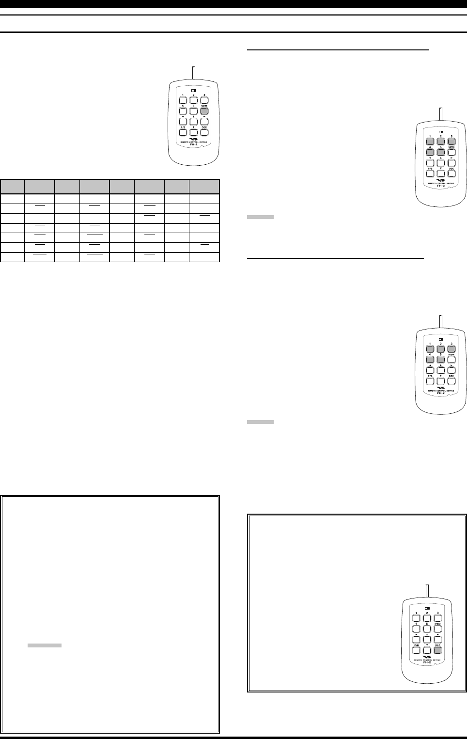
CONTEST MEMORY KEYER
The FTDX5000 in capable of the automatic sending of CW messages (as you might do in a contest) by plugging the
supplied FH-2 Remote Control Keypad into the rear panel REMOTE jack. Two techniques for message storage are avail-
able: you may either send the desired message contents using your keyer paddle (“Message Memory”), or you may input
the text characters using the (VFO-A)[SELECT] knob and (VFO-B)[SELECT] knobs (“Text Memory”).
MESSAGE Memory
Five memory channels capable of retaining 50 characters total are provided (using the PARIS standard for character and
word length).
Example: CQ CQ CQ DE W6DXC K (19 characters)
-- •-- •-- -- •-- -- •-- •-- -- •-- -- •-- •-- -- •-- -- •• • •-- -- -- •••• -- •• -- ••-- -- •-- •-- •--
(C)(Q)(C)(Q)(C)(Q)(D)(E)(W)(6)(D)(X)(C)(K)
CW CONVENIENCE FEATURES
S
TORING
A
M
ESSAGE
INTO
M
EMORY
1. Press the [MENU] button briefly, to enter the Menu
mode.
2. Rotate the (VFO-A)[SELECT] knob to select the CW
Memory Register you wish to store the message into.
For now we are just selecting the message entry tech-
nique (Keyer entry).
025 KEY CW MEM1
026 KEY CW MEM2
027 KEY CW MEM3
028 KEY CW MEM4
029 KEY CW MEM5
3. Rotate the (VFO-B)[SELECT] knob to set the selected
Memory Register to “MESSAGE”. If you want to use
your keyer paddle for message entry on all memories,
set all five Menu items (#025 ~ 029) to “MESSAGE”.
4. Press and hold in the [MENU] button for two seconds
to save the new settings and exit.
TERMINOLOGY:
PARIS Word Length: By convention in the Amateur
industry (utilized by ARRL and others), the length of one
“word” of CW is defined as the length of the Morse Code
characters spelling the word “PARIS.” This character (dot/
dash/space) length is used for the rigorous definition of
code speed in “words per minute.”
(VFO-B)[SELECT] Knob
[MENU] Button
(VFO-A)[SELECT] Knob
LOCK
OFFON
LOCK
OFFON
LOCK
OFFON
NOTE:
You must exercise care in sending to ensure that the
spaces between letters and words are accurately done.
If your timing is off, the spacing may not come out
right in the stored message.
For ease in setting up the keyer memories, we recom-
mend you set Menu item “057 A1A F-TYPE” and/or
“059 A1A R-TYPE” to “ACS” (Automatic Character
Spacing) while you are programming the keyer memo-
ries.
Page 95FTDX5000 OPERATING MANUAL
CW CONVENIENCE FEATURES
CONTEST MEMORY KEYER
C
HECKING
THE
CW M
EMORY
C
ONTENTS
1. Be sure that Break-in is still turned “off” by the [BK-
IN] button.
2. Press the [MONI] button to enable the CW monitor.
3. Press the FH-2’s [1] ~ [5] key to check
your work. You will hear the results in
the sidetone, but no RF energy will be
transmitted.
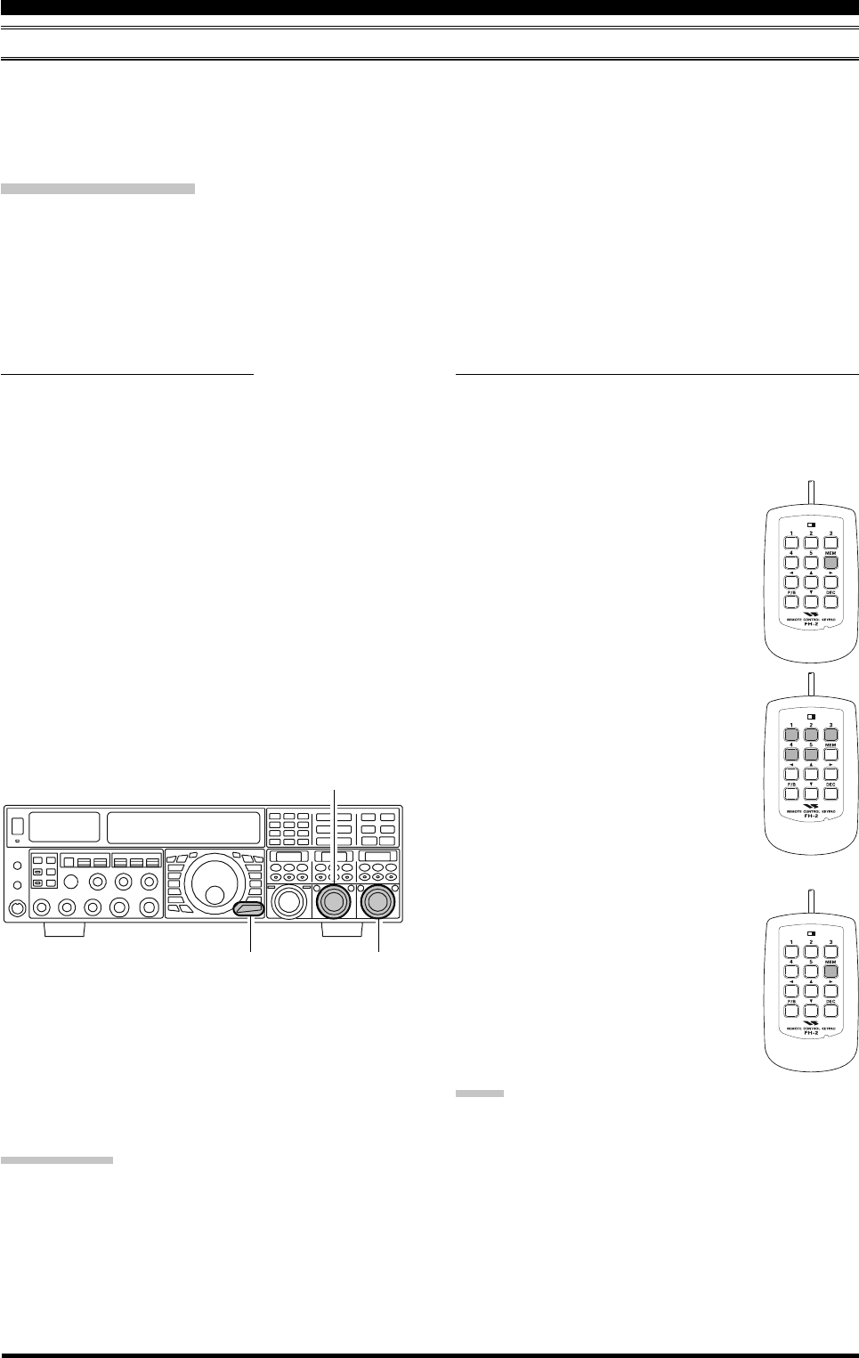
Transmitting in the Beacon Mode
It is possible to automatically transmit a “Beacon” message repetitively. The message may be input either with the
keyer paddle, or programmed using the MENU “TEXT” input method. The time delay between message repeats
may be set anywhere between 1 ~ 255 seconds via Menu item “022 KEY BEACON”. If you do not wish the
“Beacon” message to repeat, then, set this Menu item to “OFF”. Press a [1] ~ [5] key on the FH-2 Remote Control
Keypad, to select the register into which the Beacon message was stored. Repetitive transmissions of the Beacon
message will begin. Press one of these keys once more to halt the Beacon transmissions.
NOTE:
Adjust the monitor level using the [MONI] knob.
O
N
-T
HE
-A
IR
CW M
ESSAGE
P
LAYBACK
1. Press the [BK-IN] button to enable transmission. Ei-
ther Full- or Semi-break-in will be engaged, depend-
ing on the setting of Menu item “063 A1A BK-IN”.
2. Press an FH-2’s [1] ~ [5] key to trans-
mit the programmed message.
LOCK
OFFON
NOTE:
If you subsequently decide to use the “Text Memory” tech-
nique for message storage, on a particular memory regis-
ter, the contents of a message stored using the keyer paddle
input will not be transferred over when the Menu Mode
Setting is changed to “TEXT”).
LOCK
OFFON
Page 96 FTDX5000 OPERATING MANUAL
TEXT Memory
The four channels of CW message memory (up to 50 characters total) may also be programmed using the text-entry
technique. This is somewhat slower than sending the message directly from your keyer paddle, but accuracy of character
spacing is ensured. Example 1: CQ CQ CQ DE W6DXC K} (20 characters)
You may also utilize another powerful feature of the CW Memory Keyer, the sequential Contest Number (“Countup”)
feature. Example 2: 599 10 200 # K} (15 characters)
CONTEST MEMORY KEYER
STORING TEXT INTO MEMORY
1. Press the [MENU] button briefly, to enter the Menu
mode.
2. Rotate the (VFO-A)[SELECT] knob to select the CW
Memory Register you wish to store the message in.
For now, you are just selecting the message entry tech-
nique (Text entry).
025 KEY CW MEM1
026 KEY CW MEM2
027 KEY CW MEM3
028 KEY CW MEM4
029 KEY CW MEM5
3. Rotate the (VFO-B)[SELECT] knob to set the selected
Memory Register to “TEXT”. If you want to use the
Text method for message entry on all memories, set all
five Menu items (#025 ~ 029) to “TEXT”.
4. Press and hold in the [MENU] button for two seconds
to save the new settings and exit.
CW CONVENIENCE FEATURES
TEXT MESSAGE PROGRAMMING
1. Set the operating mode to CW.
2. Set the [BK-IN] button to “off”.
3. Turn the internal Electronic Keyer “on” by briefly
pressing the [KEYER] button.
4. Press the FH-2’s [MEM] key.
5. Press the [1] ~ [5] key on the FH-2 to
begin the memory storage process.
6. Use the FH-2’s [] and [] keys to
set the cursor position and use the []
and [] keys to choose the letter/num-
ber to be programmed in each slot of
the memory. In the case of the second
example above, the “#” character des-
ignates the slot where the Contest Num-
ber will appear.
ADVICE:
You may set the cursor position with the (VFO-
A)[SELECT] knob, and then choose the letter/num-
ber with the (VFO-B)[SELECT] knob.
LOCK
OFFON
LOCK
OFFON
LOCK
OFFON
CursorCurrent Cursor Position
CW Memory Register Number Message
Select the cursor position Choose the letter/number
(VFO-B)[SELECT] Knob
[MENU] Button
(VFO-A)[SELECT] Knob
Page 97FTDX5000 OPERATING MANUAL
CONTEST MEMORY KEYER
7. When the message is complete, add the “}” character
at the end to signify the termination of the message.
8. Press and hold in the FH-2 [MEM] key
for 2 seconds to exit, once all charac-
ters (including “}”) have been pro-
grammed.
CHECKING THE CW MEMORY CONTENTS
1. Be sure that Break-in is still turned “off” by the [BK-
IN] button.
2. Press the [MONI] button briefly, to enable the CW
monitor.
3. Press an FH-2 [1] ~ [5] key to check
your work. You will hear the stored
message with the CW monitor sidetone,
but no RF energy will be transmitted.
NOTE:
Adjust the monitor level using the [MONI] knob.
ON-THE-AIR CW MESSAGE PLAYBACK
1. Press the [BK-IN] button briefly to enable transmis-
sion. Either Full- or Semi-break-in will be engaged de-
pending on the setting of Menu item “063 A1A BK-
IN.”
2. Press the FH-2’s [1] ~ [5] key to trans-
mit the programmed message.
NOTE:
If you subsequently decide to use the “Message Memory”
technique for message storage, on a particular memory
register, the contents of the message stored using text in-
put will not be transferred over when you select the “Mes-
sage Memory” technique (the Menu Mode Setting is set
to “MESSAGE”).
Contest Number Programming
Use this process if you are starting a contest, or if
you somehow get out of sync with the proper num-
ber in the middle of a contest.
1. Press the [MENU] button briefly, to enter the
Menu mode.
2. Rotate the (VFO-A)[SELECT] knob to select
Menu item “024 KEY CONTEST”.
3. Rotate the (VFO-B)[SELECT] knob to set the
Contest Number to the desired value.
ADVICE:
Press the [CLEAR] button briefly (located
above the [CLAR(VFO-B)] knob), to reset the
Contest Number to “1”.
4. Press and hold in the [MENU] button for two
seconds to store the new number and exit to
normal operation.
CW CONVENIENCE FEATURES
LOCK
OFFON
LOCK
OFFON
LOCK
OFFON
LOCK
OFFON
Decrementing the Contest Number
Use this process if the current contest number gets
ahead of the actual number you want to send (in
case of a duplicate QSO, for example).
Press the FH-2 control’s [DEC] key.
The current Contest Number will be
reduced by one. Press the [DEC]
button briefly, as many times as nec-
essary, to reach the desired number.
If you go too far, use the “Contest
Number Programming” technique
desireded at the left.
TEXT
!
“””
#
$
%
&
‘’’
CW CODE
SN
AF
---
SX
KA
AS
WG
TEXT
(
“)”
*
+
,
---
.
CW CODE
KN
KK
---
AR
MIM
DU
AAA
TEXT
/
“:”
;
<
=
>
?
CW CODE
DN
OS
KR
---
BT
---
IMI
TEXT
@
“[”
\
]
^
_
‘}’
CW CODE
@
---
AL
---
---
IQ
---
Page 98 FTDX5000 OPERATING MANUAL
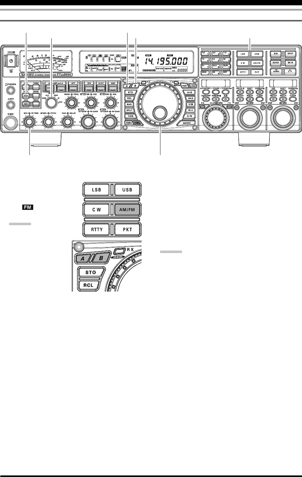
FM MODE OPERATION
BASIC OPERATION
1. To select the FM operating
mode, press the [AM/FM]
button several times, until
the “ ” icon appears in
the display, .
ADVICE:
The operating mode is
selected using the
[MODE] button,
and then pressing the
[A] or [B] button
(located to the upper
left of the Main Tun-
ing Dial knob), to
choose VFO-A or VFO-B, to which the selection is
applied. Usually, the [A] button glows red, signify-
ing VFO-A is being adjusted. Similarly, pressing
the [B] button will cause its indicator to glow or-
ange, signifying VFO-B adjustment. Therefore,
press the [A] or [B] button to select the desired
VFO, then press the [AM/FM] button to select the
FM mode.
2. Rotate the Main Tuning Dial knob (in the case of VFO-
A operation) to tune the desired operating frequency.
Pressing the microphone [UP] or [DWN] button will
cause the frequency to change in 5 kHz steps.
3. Press the microphone PTT switch (or press the front
panel [MOX] button) to transmit. Speak into the mi-
crophone in a normal voice level. Release the PTT or
[MOX] switch to return to receive.
Main Tuning Dial knob
[METER] Switch [B] Button
[MOX] Button
[MODE] Buttons
[MIC] Knob
[RF PWR] Knob
[A] Button
4. There are two methods of adjusting the microphone
gain for FM operation. At the factory, a default level
has been programmed that should be satisfactory for
most situations. However, using Menu item “079 F3E
MICGAIN”, you may set a different fixed value, or
you may choose the “MCVR” option which then lets
you use the front panel [MIC] knob to set the micro-
phone gain in the FM mode.
ADVICE:
The Transmit Monitor is another helpful way of veri-
fying proper adjustment of the FM MIC Gain. By press-
ing the [MONI] button, and then adjusting the [MONI]
knob for a comfortable listening level while you are
transmitting, you will be able to hear the difference in
deviation as you make adjustments.
FM is only used in the 28 MHz and 50 MHz Amateur
bands covered in the FTDX5000. Please do not use
FM on any other bands.
Page 99FTDX5000 OPERATING MANUAL
FM MODE OPERATION
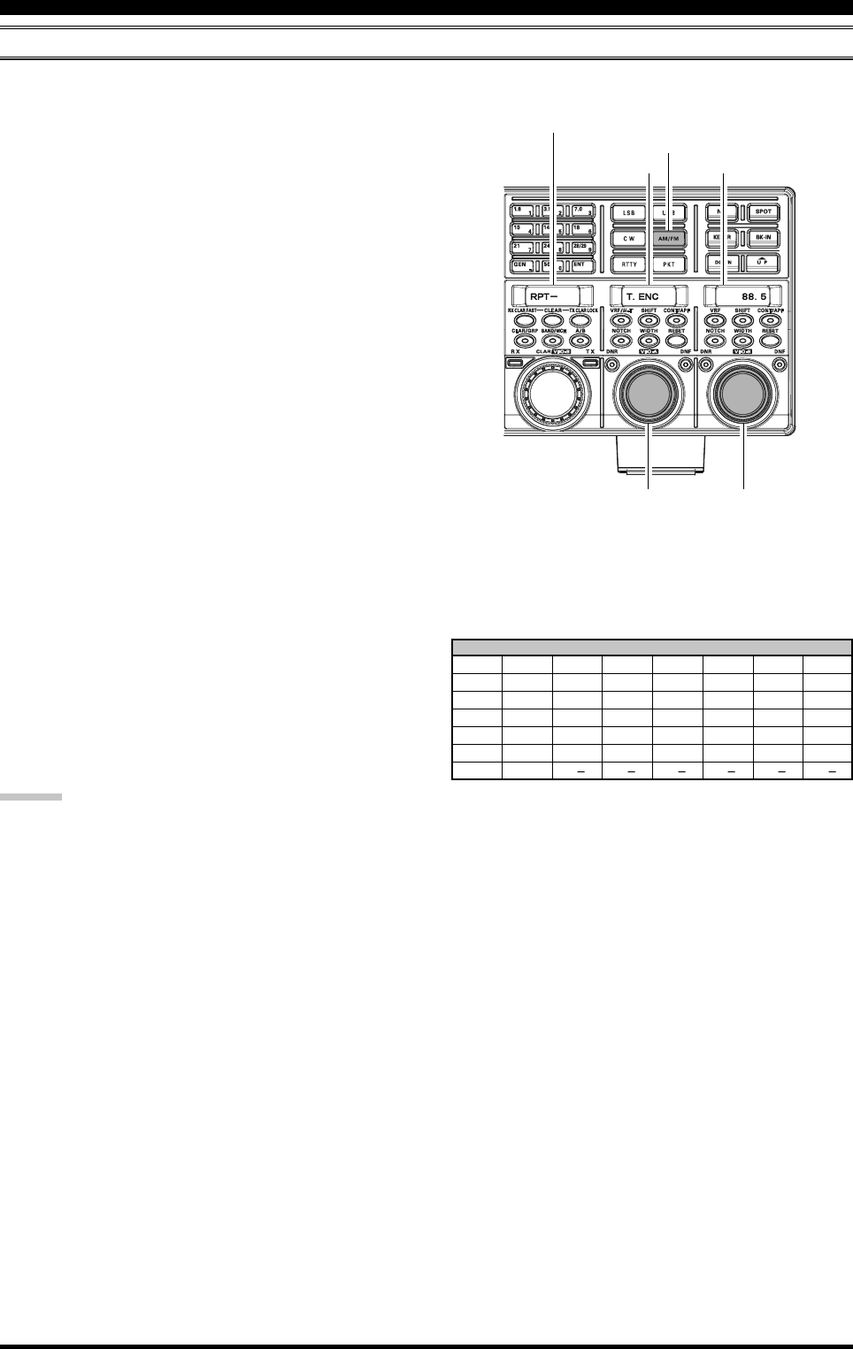
REPEATER OPERATION
CTCSS TONE FREQUENCY (Hz)
67.0 69.3 71.9 74.4 77.0 79.7 82.5 85.4
88.5 91.5 94.8 97.4 100.0 103.5 107.2 110.9
114.8 118.8 123.0 127.3 131.8 136.5 141.3 146.2
151.4 156.7 159.8 162.2 165.5 167.9 171.3 173.8
177.3 179.9 183.5 186.2 189.9 192.8 196.6 199.5
203.5 206.5 210.7 218.1 225.7 229.1 233.6 241.8
250.3 251.4
ADVICE:
The conventional repeater shift used on 29 MHz is 100 kHz, while on the 50 MHz band the shift may vary between 500 kHz
and 1.7 MHz (or more). To program the proper repeater shift, use Menu items “081 F3E 28 RPT” (28 MHz) and “082 F3E
50 RPT” (50 MHz), as appropriate.
The FTDX5000 may be utilized on 29 MHz and 50 MHz repeaters.
1. Rotate the Main Tuning Dial knob to the output fre-
quency (downlink) from the repeater.
2. If CTCSS Tone operation is desired/needed, press and
hold in the [AM/FM] button for two seconds to en-
gage the CTCSS mode.
3. Within 5 seconds of pressing of the [AM/FM] button:
Rotate the (VFO-A)[SELECT] knob to select the
desired CTCSS mode. If you just need to send the
uplink encoding tone, select “T.ENC”. For encode/
decode operation, choose “T.SQL” instead. The
available choices are
“OFF” “T.ENC” “T.SQL” “OFF”.
Rotate the (VFO-B)[SELECT] knob to select the
desired CTCSS Tone to be used. A total of 50 stan-
dard CTCSS tones are provided (see the CTCSS
Tone Chart).
Press the [AM/FM] button briefly, to select the de-
sired repeater shift direction. The selections are
“RPT SIMP
(not used on a repeater)
” “RPT +”
“RPT –” “RPT SIMP
(not used on a repeater)
”.
4. Press and hold in the [AM/FM] button for two seconds
to exit from the repeater setup mode.
5. Close the microphone PTT switch (or press the [MOX]
button) to begin transmission. You will observe that
the frequency has shifted to correspond with the pro-
gramming you set up in the previous steps. Speak into
the microphone in a normal voice level, and then re-
lease the PTT switch or [MOX] button to return to the
receive mode.
CTCSS Tone
Select the Repeater Shift Direction
Repeater Shift Direction
Select the CTCSS Mode Select the CTCSS Tone
CTCSS Mode

Page 100 FTDX5000 OPERATING MANUAL
CONVENIENT MEMORY FUNCTIONS
The FTDX5000 contains ninety-nine regular memories, labeled “01” through “99”; nine specialy programmed limit memory
pairs, labeled “P1L/P1U” through “P9L/P9U”; and five QMB (Quick Memory Bank) memories, labeled “C-1” through
“C-5”. Each memory location not only stores the VFO-A frequency and mode, but also stores the various settings shown
below. By default the 99 regular memories are contained in one group. However, they can be arranged in up to six separate
groups, if desired.
QUICK POINT:
The FTDX5000’s memory channels store the following data (in addition to the operating frequency):
Frequency
Mode
Clarifier status and its Offset Frequency
ANT status
ATT status
IPO status
VRF status
Roofing filter status and its Bandwidth
Noise Blanker status
CONTOUR status and its Peak Frequency
DSP Noise Reduction (DNR) status and its Reduction algorithm selection.
DSP Notch filter (NOTCH) status
NAR bandwidth status
DSP Auto Notch filter (DNF) status
Repeater Shift Direction and CTCSS Tone Frequency
MEMORY OPERATION
IMPOTANT NOTE
On rare occasions the stored data may become cor-
rupted by miss operation, or static electricity. When
repairs are made, the memory data may be lost.
Please write down or record the memory informa-
tion so you will be able to restore it if needed.
Page 101FTDX5000 OPERATING MANUAL
MEMORY OPERATION
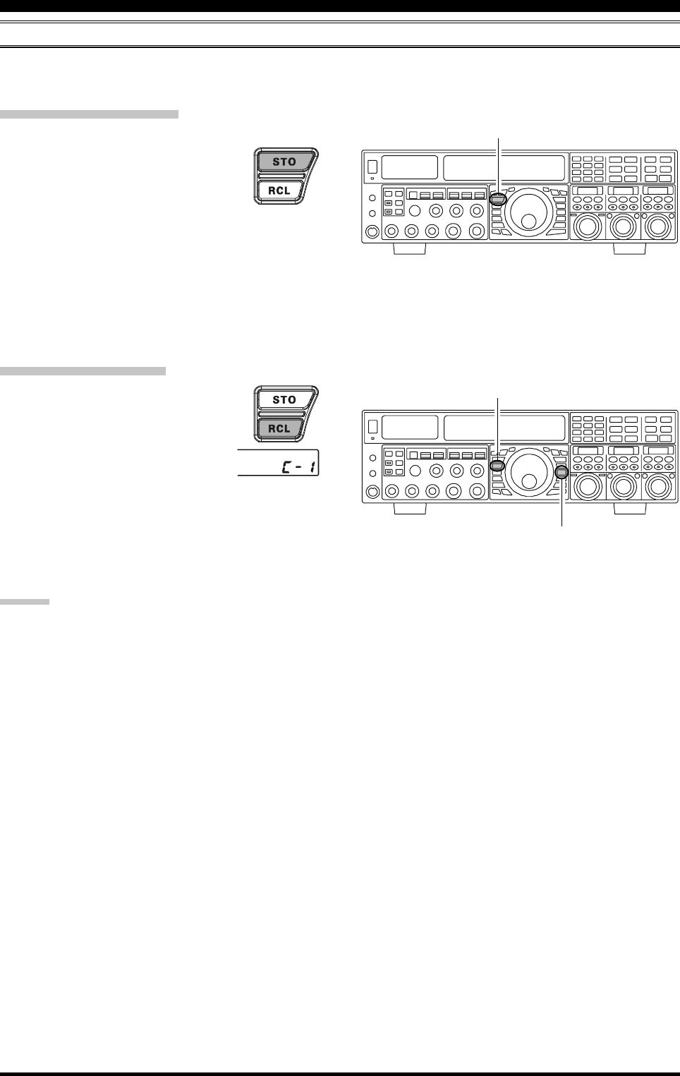
QMB (QUICK MEMORY BANK)
The Quick Memory Bank consists of five memories (labeled “C-1” through “C-5.”) independent from the regular and PMS
memories. These can quickly store operating parameters for later recall.
QMB Channel Storage
1. Tune to the desired frequency on VFO-A.
2. Press the blue [STO] button briefly. The
“beep” will confirm that the contents of
VFO-A have been written to the currently
available QMB memory.
3 If you repeatedly press the [STO] button, the QMB
memories will be written in the following order:
C-2 C-3 C-4 C-5 C-1 ......
Once all five QMB memories have data in them, previous
data (starting with channel “C-1”) will be over-written, on
a first-in, first-out basis.
QMB Channel Recall
1. Press the blue [RCL] button briefly. The
current QMB channel data will be shown
on the VFO-A frequency display field,
and the QMB memory channel num-
ber will appear in the small window at
the lower right corner of the display.
2. Repeatedly pressing the [RCL] button will rotate
through the QMB channels:
C-2 C-3 C-4 C-5 C-1 ......
3. Press the [V/M] button briefly, to return to the VFO or
Memory mode.
ADVICE:
Rotating the Main Tuning Dial knob, or changing the op-
erating mode will place the transceiver in the “Memory
Tune” mode. This is a temporary “pseudo-VFO” method
of tuning off of a stored memory channel. If you do not
over-write the contents of the current memory channel,
the original contents will not be disturbed by the initiation
of Memory Tune operation.
[STO] Button
[RCL] Button
[V/M] Button
Page 102 FTDX5000 OPERATING MANUAL
MEMORY OPERATION
REGULAR MEMORY OPERATION
The Regular Memory of the FTDX5000 allows storage and recall of up to 99 memories, each storing frequency, mode, and
a wide variety of status information detailed previously. Memories may be grouped into as many as six Memory Groups.
Additionally, you get nine pairs of band-limit (PMS) memories, and five QMB (Quick Memory Bank) memories.
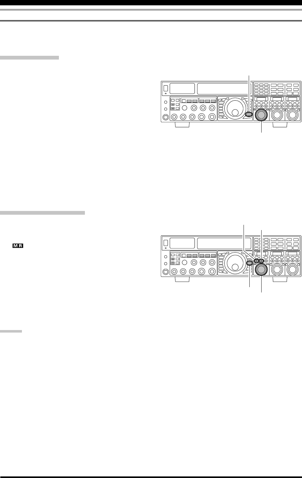
Memory Storage
1. Set VFO-A up with frequency, mode, and status infor-
mation, the way you want to have it stored.
2. Press the [A
M] button briefly (the current channel
number will start blinking in the small window at the
lower right corner of the display), and the contents of
the current memory channel will be shown on the SUB
DISPLAY-I.
3. Rotate the [CLAR(VFO-B)] knob to select the memory
channel onto which you wish to store the data. If you
have selected a channel in which data is already stored,
that frequency will appear on the SUB DISPLAY-I
window.
4. Press and hold in the [A
M] button for two seconds
to store the frequency and other data into the selected
memory channel. A double beep will confirm that you
have held the [A
M] button in long enough.
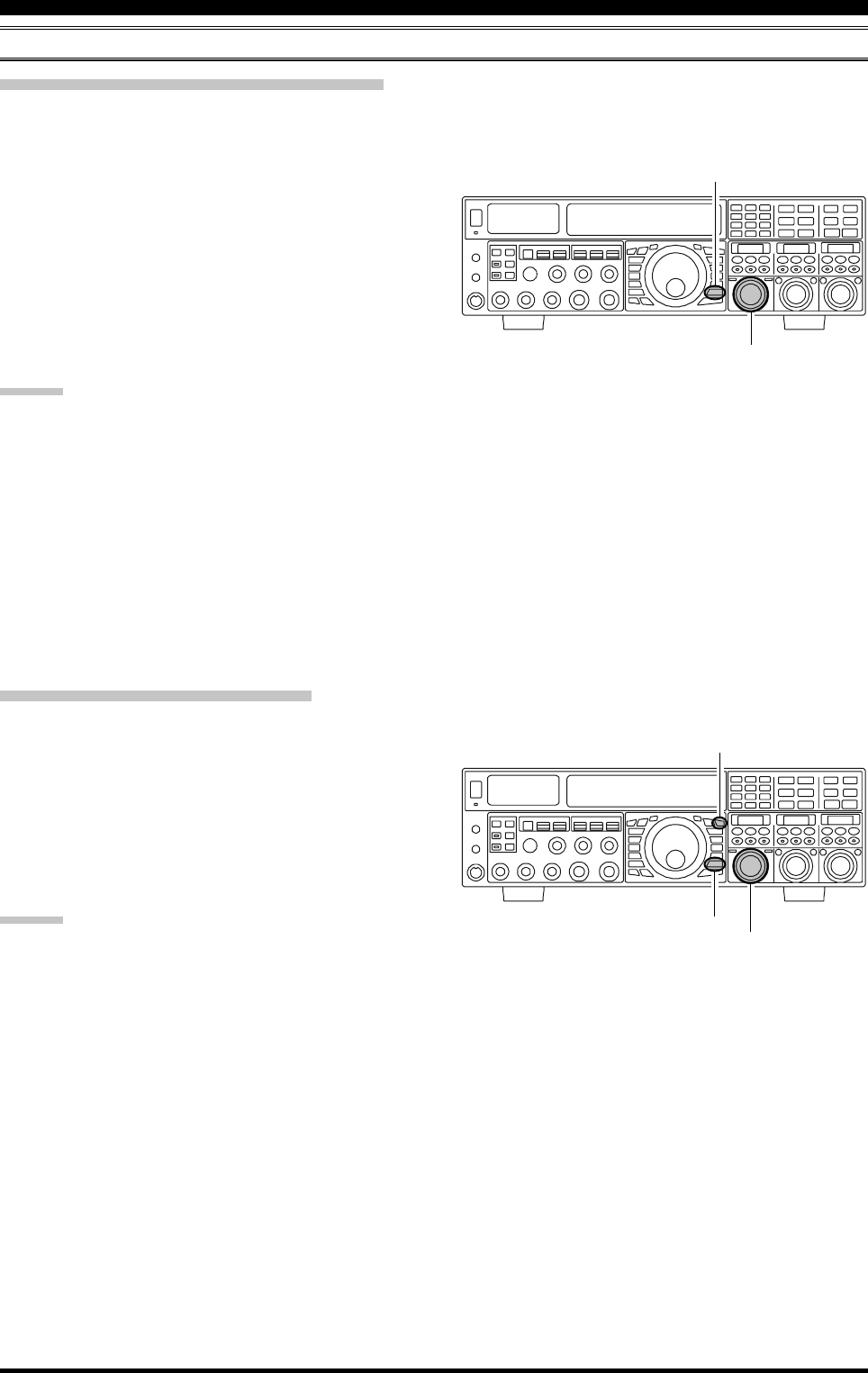
Memory Channel Recall
1. Press the [V/M] button briefly, if necessary, to enter
the Memory mode. The memory channel data will be
shown on the VFO-A frequency display field, and the
“” icon and memory channel number will appear
in the small window at the lower right corner of the
display.
2. Press and hold the [BAND/MCH] button for two sec-
onds. The [BAND/MCH] button glows yellow, indi-
cating that you are ready to select a memory channel
using the [CLAR(VFO-B)] knob.
3. After pressing the [BAND/MCH] button, you may ro-
tate the [CLAR(VFO-B)] knob to select the desired
memory channel.
ADVICE:
To work within a particular Memory Group (described on
page 105), press and hold the [CLAR/GRP] button for
two seconds (the button will glow yellow), then rotate the
[CLAR(VFO-B)] knob to select the desired Memory
Group. Now press and hold the [BAND/MCH] button for
two seconds (the [BAND/MCH] button will glow yellow).
You may now choose the memory channel within the se-
lected Memory Group.
[CLAR(VFO-B)] Knob
[A
M] Button
[CLAR(VFO-B)] Knob
[V/M] Button
[BAND/MCH] Button
[CLAR/GRP] Button
Page 103FTDX5000 OPERATING MANUAL
Checking a Memory Channel’s Status
Before programming a channel into memory, you can check the current contents of that channel without the danger of
overwriting the channel accidentally.
MEMORY OPERATION
REGULAR MEMORY OPERATION
1. Press the [A
M] button briefly.
The data stored in the currently-selected memory chan-
nel will be displayed in the SUB DISPLAY-I win-
dow. However, since you are only checking the con-
tents of the memory channel, your radio will not have
moved to the memory channel’s frequency.
2. Rotate the [CLAR(VFO-B)] knob to select a different
memory channel. To exit from the Memory Check
mode, press the [A
M] button briefly, once more.
ADVICE:
While the Memory Check function is engaged, the
memory channel number will blink in the multi-panel
window.
While operating in the VFO mode, using Memory
Check, you may store the current contents of the VFO-
A register into the selected memory by pressing and
holding in the [A
M] button for two seconds (listen
for the double beep). Conversely, if you wish to write
the contents of the current memory into the VFO-A
register, press and hold in the [M
A] button for two
seconds.
Erasing Memory Channel Data
1. Press the [A
M] button briefly.
The data stored in the currently-selected memory chan-
nel will be displayed in the SUB DISPLAY-I win-
dow.
2. Rotate the [CLAR(VFO-B)] knob to select the memory
channel that you would like to erase.
3. Press the [LOCK] button briefly, to erase the contents
of the selected memory channel.
ADVICE:
After erasure, only the memory channel number will
remain. The frequency data will disappear from the
display.
If you make a mistake and wish to restore the memory
contents, just repeat steps (1) through (3) above.
[CLAR(VFO-B)] Knob
[A
M] Button
[CLAR(VFO-B)] Knob
[A
M] Button
[LOCK] Button
Page 104 FTDX5000 OPERATING MANUAL
MEMORY OPERATION
REGULAR MEMORY OPERATION
Moving Memory Data to the VFO-A
You may transfer the contents of the currently selected memory channel into the Main band (VFO-A) register, if you like.
1. Press the [V/M] button briefly, as necessary, to enter
the Memory mode. The memory channel number will
appear in the small window at the lower right corner of
the display.
2. Press and hold the [BAND/MCH] button for two sec-
ond. The [BAND/MCH] button will glow yellow, in-
dicating that you are ready to select a memory channel
using the [CLAR(VFO-B)] knob.
3. Rotate the [CLAR(VFO-B)] knob to select the memory
channel you wish to transfer to VFO-A.
4. Press and hold in the [M
A] button for two seconds,
until you hear the double beep. The data in the selected
memory channel will now be transferred to the VFO-
A.
ADVICE:
The transfer of data to the VFO-A does not affect the origi-
nal contents of the memory channel. This is a “copy” func-
tion that leaves the memory contents unchanged.
1. Press the [V/M] button briefly, to recall any memory
channel.
2. Rotate the Main Tuning Dial knob and you will see
that the memory channel frequency is changing.
ADVICE:
The “ ” icon will replace the “ ” icon in
the small window at the lower right corner of the
display, indicating you are in the “Memory Tune”
mode.
During Memory Tune operation, you may change
operating modes, and engage the Clarifier, if de-
sired.
3. Press the [V/M] button briefly to return to the origi-
nally-memorized frequency of the current memory
channel. One more brief press of the [V/M] button will
return you to VFO operation.
NOTE:
Computer software programs utilizing the CAT system
interface port may presume that the transceiver is operat-
ing in the VFO mode for certain features like “band map-
ping” and/or frequency logging. Because the “Memory
Tune” mode so closely resembles the VFO mode, be sure
that you have the FTDX5000 operating in a control mode
compatible with your software requirements. Use the VFO
mode if you’re not sure.
Memory Tune Operation
You may freely tune the frequency off of any memory channel in a “Memory Tune” mode. This is similar to VFO operation.
So long as you do not over-write the contents of the current memory, Memory Tune operation will not alter the contents of
the memory channel.
[CLAR(VFO-B)] Knob
[M
A] Button
[BAND/MCH] Button
[V/M] Button
[V/M] Button
Main Tuning Dial Knob
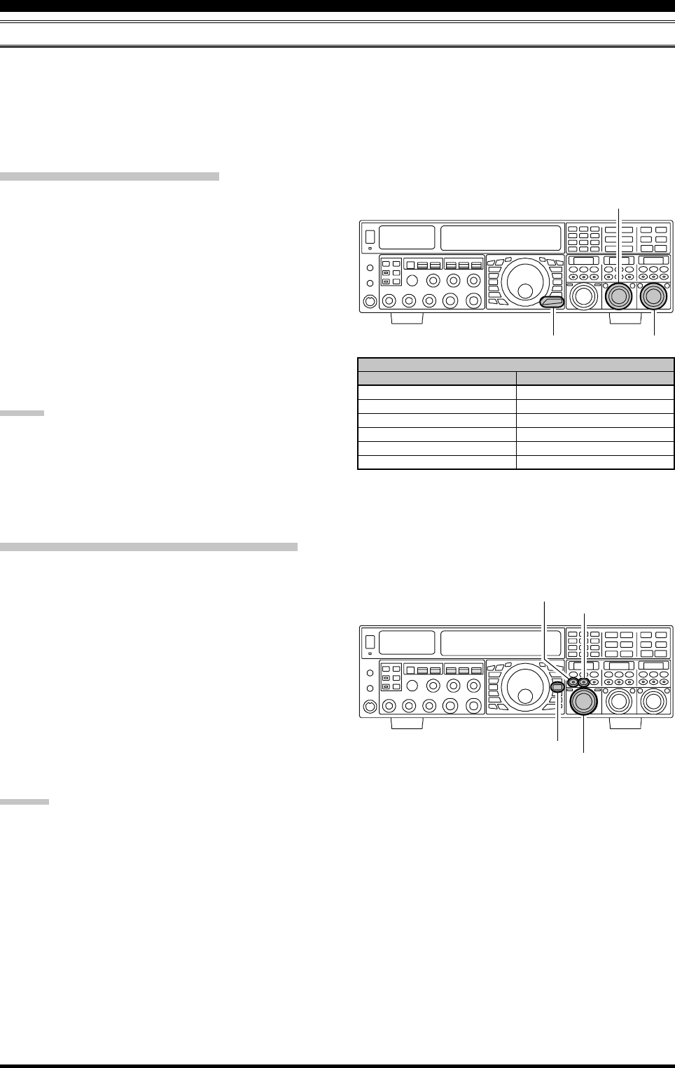
Page 105FTDX5000 OPERATING MANUAL
MEMORY GROUPS
Memory channels may be grouped into as many as six convenient batches, for easy identification and selection. For ex-
ample, you might want to set aside memory groups for AM BC stations, shortwave broadcast stations, contest frequencies,
repeater frequencies, and PMS limits, or any other groupings you like.
Each memory group is capable of holding up to 19 or 20 memory channels (the Group size is fixed). When a memory
channel is grouped, the channel numbers change to correspond to the chart below:
Memory Group Assignment
1. Press the [MENU] button briefly, to enter the Menu
mode.
2. Rotate the (VFO-A)[SELECT] knob to select Menu
item “032 GENE MEM GRP”.
3. Rotate the (VFO-B)[SELECT] knob to set this Menu
item to “ENABLE” (the default setting is “DISABLE”).
4. Press and hold in the [MENU] button for two seconds
to save the new setting and exit. Operation will now be
restricted to the six Memory Groups.
To cancel Memory Group operation, repeat steps (1)
through (4) above, choosing “DISABLE” in step (3).
ADVICE
Note that for the PMS memory group, the PMS memories
“P1L” through “P9U” will be so designated, to avoid con-
fusion.
Choosing the Desired Memory Group
You may recall memories just within a particular Memory
Group, if desired.
1. Press the [V/M] button briefly, if necessary to enter the
Memory mode.
2. Press and hold the [CLAR/GRP] button for two sec-
onds. The [CLAR/GRP] button will glow yellow.
3. Rotate the [CLAR(VFO-B)] knob to select the desired
Memory Group.
4. Press and hold the [BAND/MCH] button. The [BAND/
MCH] button will glow yellow.
5. Rotate the [CLAR(VFO-B)] knob to select the desired
Memory Channel within the Selected Memory Group.
ADVICE:
If no channels have been assigned to a particular Memory
Group, you will not have access to that Group.
MEMORY OPERATION
(VFO-B)[SELECT] Knob
[MENU] Button
(VFO-A)[SELECT] Knob
GROUP MEMORY “OFF”
01 ~ 19
20 ~ 39
40 ~ 59
60 ~ 79
80 ~ 99
P-1L/1U ~ P-9L/9U
MEMORY CHANNEL NUMBER
GROUP MEMORY “ON”
1-01 ~ 1-19
2-01 ~ 2-20
3-01 ~ 3-20
4-01 ~ 4-20
5-01 ~ 5-20
P-1L/1U ~ P-9L/9U
[CLAR(VFO-B)] Knob
[V/M] Button
[BAND/MCH] Button
[CLAR/GRP] Button
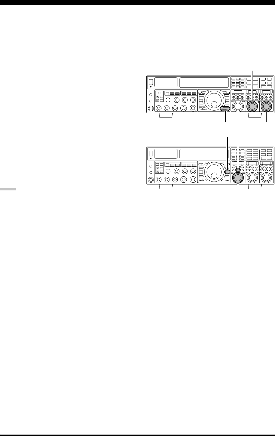
Page 106 FTDX5000 OPERATING MANUAL
Section 97.401(d) of the regulations governing amateur radio in the United States permits emergency amateur communica-
tions on the spot frequency of 5167.5 kHz by stations in (or within 92.6 km of) the state of Alaska. This frequency is only
to be used when the immediate safety of human life and/or property are threatened. It is never to be used for routine
communications.
The FTDX5000 includes the capability for transmission and reception on 5167.5 kHz under such emergency conditions via
the Menu system. To activate this feature:
1. Press the [MENU] button to briefly, enter the Menu
mode.
2. Rotate the (VFO-A)[SELECT] knob to select “176
TGEN EMRGNCY”.
3. Rotate the (VFO-B)[SELECT] knob to select “EN-
ABLE”.
4. Press and hold in the [MENU] button for 2 seconds to
save the new setting and exit to normal operation. Emer-
gency communication on this spot frequency is now
possible.
5. Press the [V/M] button, as necessary, to enter the
Memory mode. Press and hold the [BAND/MCH] but-
ton (the imbedded LED glows yellow), then rotate the
[CLAR(VFO-B)] knob to select the emergency chan-
nel (“E-US”), which is found between channels “P-9U”
and “01.”
NOTE:
The receive-mode CLARIFIER functions normally
while using this frequency, but variation of the trans-
mit frequency is not possible. Activation of “176 TGEN
EMRGNCY” does not enable any other out-of-ama-
teur-band capability on the transceiver. The full speci-
fications of the FTDX5000 are not necessarily guaran-
teed on this frequency. However, power output and re-
ceiver sensitivity should be fully satisfactory for the
purpose of emergency communication.
If you wish to disable operation capability on the Alaska
Emergency Frequency, repeat the above procedures,
but set “176 TGEN EMRGNCY” to “DISABLE” in
step 3.
In an emergency, note that a half-wave dipole cut for
this frequency should be approximately 45’3” on each
leg (90’6” total length). Emergency operation on
5167.5 kHz is shared with the Alaska-Fixed Service.
This transceiver is not authorized for operation under
the FCC’s Part 87 rules for aeronautical communica-
tions.
O
PERATION
ON
A
LASKA
E
MERGENCY
F
REQUENCY
:
5167.5
KH
Z
(U.S. V
ERSION
O
NLY
)
(VFO-B)[SELECT] Knob
[MENU] Button
(VFO-A)[SELECT] Knob
[CLAR(VFO-B)] Knob
[BAND/MCH] Button
[V/M] Button
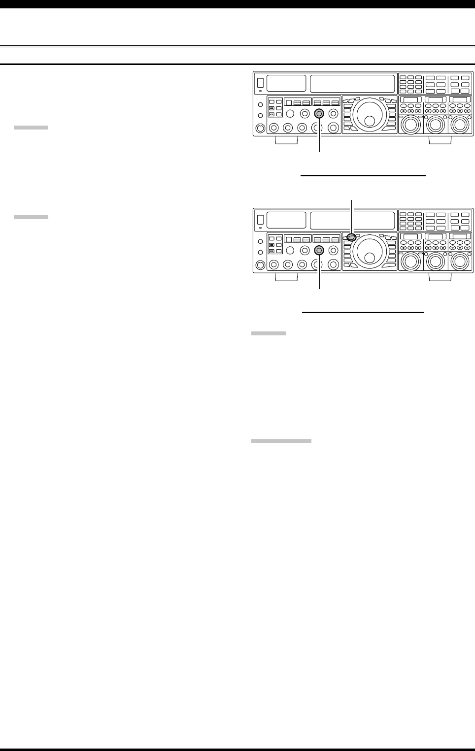
Page 107FTDX5000 OPERATING MANUAL
You may scan either the VFO or the memories of the FTDX5000. The radio will halt scanning on any station with a signal
strong enough to open the receiver squelch.
VFO SCANNING
VFO AND MEMORY SCANNING
1. Set the VFO to the frequency on which you would like
to begin scanning.
2. Rotate the (VFO-A)[SQL] knob so that the background
noise is just silenced.
ADVICE:
If you would like to scan on VFO-B, rotate the (VFO-
B)[SQL] knob so that the background noise is just si-
lenced.
3. Press and hold in the microphone [UP] or [DWN] key
for 1/2 second to start scanning in the specified direc-
tion on the VFO-A.
ADVICE:
If you would like to begin scanning on the VFO-B,
press the [B] button briefly, first (located to the upper
left of the Main Tuning Dial knob), then press and hold
in the microphone [UP] or [DWN] key for 1/2 second.
4. The scanner will now increment the frequency in the
chosen direction until a signal is detected. When a sig-
nal is encountered which opens the squelch, receiver
will respond differently, depending on the operating
mode:
In the SSB/CW modes, the decimal points in the
frequency display area will blink and the scanner
will slow down (but does not stop).
In the FM/AM modes, the transceiver pauses on
the signal and stays locked on its frequency for five
seconds. Thereafter, scanning will resume whether
or not the other station’s transmission has ended.
While the transceiver is in the “pause” condition,
the decimal points in the frequency display area
will blink. If the incoming signal disappears, scan-
ning will resume.
5. To cancel scanning, press the microphone [UP] or
[DWN] key briefly.
MAIN BAND (VFO-A) SCANNING
SUB BAND (VFO-B) SCANNING
(VFO-B)[PICTH] Knob
[B] Button
(VFO-B)[PICTH] Knob
ADVICE:
You may select the manner in which the scanner resumes
while it has paused on a signal in the FM/AM modes, us-
ing Menu item “045 GENE SCN RSM”. The default
“TIME” setting will cause the scanner to resume scanning
after five seconds; you may change it, however, to resume
only after the carrier has dropped out, if you like See page
125.
QUICK POINT:
If you have no interest in scanning, and wish to prohibit
the microphone’s [UP]/[DWN] keys from initiating scan-
ning, you may disable scanning control from the micro-
phone using Menu item “044 GENE MIC SCN” (set it to
“DISABLE”).
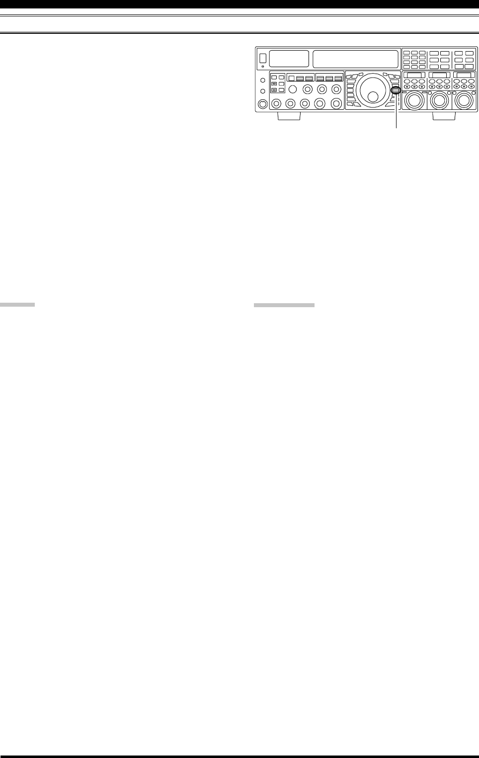
Page 108 FTDX5000 OPERATING MANUAL
MEMORY SCAN
VFO AND MEMORY SCANNING
1. Set the transceiver up in the memory mode by pressing
the [V/M] button briefly, if necessary.
2. Rotate the (VFO-A)[SQL] knob so that the background
noise is just silenced.
3. Press and hold in the microphone’s [UP] or [DWN]
key for 1/2 second to start scanning in the specified
direction.
4. The scanner will now cause the transceiver to incre-
ment in the chosen direction until a signal is detected.
When a signal is encountered which opens the squelch,
the transceiver pauses on the signal and stays locked
on its frequency for five seconds. Thereafter, scanning
will resume whether or not the other station’s trans-
mission has ended. While the transceiver is in the
“pause” condition, the decimal points in the frequency
display area will blink.
5. If the incoming signal disappears, scanning will resume.
6. To cancel the scanning, press the microphone’s [UP]
or [DWN] key briefly.
ADVICE:
During Memory Group operation, only the channels
within the current Memory Group will be scanned.
If the scan has paused on a signal, pressing the
microphone’s [UP] or [DWN] key will cause scanning
to resume instantly.
If you press the microphone’s PTT switch during scan-
ning, the scanner will halt at once. Pressing the PTT
switch during scanning will not cause transmission,
however.
You may select the manner in which the scanner re-
sumes while it has paused on a signal, using Menu item
“045 GENE SCN RSM”. The default “TIME” setting
will cause the scanner to resume scanning after five
seconds; you may change it, however, to resume only
after the carrier has dropped out, if you like See page
125.
QUICK POINT:
If you have no interest in scanning, and wish to prohibit
the microphone’s [UP]/[DWN] keys from initiating scan-
ning, you may disable scanning control from the micro-
phone using Menu item “044 GENE MIC SCN” (set it to
“DISABLE”).
[V/M] Button

Page 109FTDX5000 OPERATING MANUAL
To limit scanning (and manual tuning) within a particular frequency range, you can use the Programmable Memory Scan-
ning (PMS) feature, which utilizes nine special-purpose memory pairs (“P1L/P1U” through “P9L/P9U”). The PMS fea-
ture is especially useful in helping you to observe any operating sub-band limits which apply to your Amateur license class.
1. Store the Lower and Upper tuning/scanning limit fre-
quencies into the memory pair “P1L” and “P1U,” re-
spectively, or any other “L/U” pair of memories in the
special PMS memory area. See page 102 for details
regarding memory storage.
2. Press the [V/M] button briefly, to enter the Memory
mode.
3. Press and hold the [BAND/MCH] button for two sec-
onds. The [BAND/MCH] button will glow yellow, in-
dicating that you may select a memory channel using
the [CLAR(VFO-B)] knob.
4. Rotate the [CLAR(VFO-B)] knob to select memory
channel “P1L” or “P1U.”
5. Rotate the (VFO-A)[SQL] knob so that the background
noise is just silenced.
6. Turn the Main Tuning Dial knob slightly (to activate
memory tuning). Tuning and scanning are now limited
to the range within the P1L/P1U limits until you press
the [V/M] button briefly, to return to memory channel
or VFO-A operation.
7. Press and hold in the microphone’s [UP] or [DWN]
key for 1/2 second to start scanning in the specified
direction.
8. The scanner will now cause the transceiver to incre-
ment in the chosen direction until a signal is detected.
When a signal is encountered which opens the squelch,
it will do different things, depending on the operating
mode:
In the SSB/CW modes, the decimal points in the
frequency display area will blink and the scanner
will slow down (but does not stop).
In the FM/AM modes, the transceiver pauses on
the signal and stays locked on its frequency for five
seconds. Thereafter, scanning will resume whether
or not the other station’s transmission has ended.
While the transceiver is in the “pause” condition,
the decimal points in the frequency display area
will blink. If the incoming signal disappears, scan-
ning will resume.
9. If you rotate the Main Tuning Dial knob in the oppo-
site direction from the current scanning direction (in
other words, you rotate the dial to the left when scan-
ning toward a higher frequency), the direction of the
scan will reverse.
10. If you press the microphone PTT switch during scan-
ning, the scanner will halt at once. Pressing the PTT
switch during scanning will not cause transmission,
however.
PMS (PROGRAMMABLE MEMORY SCANNING)
[CLAR(VFO-B)] Knob
[V/M] Button
[BAND/MCH] Button
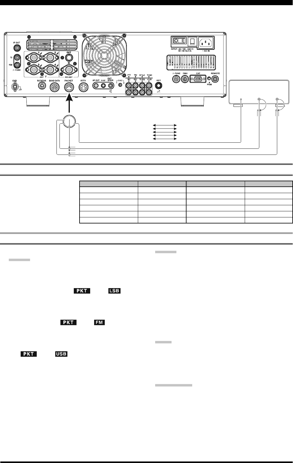
Page 110 FTDX5000 OPERATING MANUAL
Packet operation is easily accomplished on the FTDX5000 by connecting your TNC (Terminal Node Controller) to the
transceiver, as in the illustration. “Packet” operation also applies to SSB-based AFSK data modes, such as PSK31, etc.
PACKET OPERATION
PACKET SETUP (INCLUDING SUBCARRIER FREQUENCY)
Before operation can com-
mence, some basic setup proce-
dures must be performed, using
the Menu, to configure your ra-
dio for the desired data mode.
BASIC SETUP
1. Press the [PKT] button.
ADVICE:
For HF operation, SSB-based data operation is gen-
erally used. One brief press of the [PKT] button
will engage packet operation in the “LSB” mode
(by default). Both the “ ” and “ ” icons
will appear in the display.
To operate FM-based 1200-baud packet on the 29/
50 MHz bands, press the [PKT] button repeatedly
to illuminate the “ ” and “ ” icons, to en-
gage the “PKT-FM” mode.
To engaged Packet operation in the “USB” mode,
repeat pressing the [PKT] button until both the
“” and “ ” icons are appear.
2. When the “transmit” command is received from the
TNC, the FTDX5000 transmitter will automatically be
engaged. Likewise, the command to return to receive
will cause the radio to revert to the receive mode.
ADVICE:
If you need to adjust the output level from the “DATA
OUT” pin of the PACKET jack (pin 4) on the radio,
use Menu item “072 DATA OUT LVL”. For the input
level from the TNC, as applied to the DATA IN pin of
the PACKET jack (pin 1), use Menu item “070 DATA
DT GAIN”.
During Packet operation via the rear panel PACKET
jack, the front panel MIC jack is cut off, so you won’t
have a “live microphone” problem during data opera-
tion.
NOTE:
If you anticipate making data transmissions of longer than
a few minutes, we recommend that you use the [RF PWR]
knob to reduce the transmitter power to 1/3 ~ 1/2 of its
normal maximum.
QUICK POINT:
PACKET Jack Specifications
DATA IN (Pin 1)
Input Level: 50 mVp-p
Input Impedance: 10 k-Ohms
DATA OUT (Pin 4)
Output Level: 100 mVp-p max.
Output Impedance: 10 k-Ohms
DATA
OUT
PTT
DATA
IN
①
⑤④
③
②
PACKET
PACKET JACK TNC
Pin 1 (DATA IN)
Pin 2
Pin 3
Pin 4
Pin 5
(GND)
(PACKET PTT)
(DATA OUT)
(BUSY)
DATA OUT
GND
PTT
DATA IN
(SQL Control)
MENU ITEM
069 DATA DATA IN
070 DATA DT GAIN
071 DATA DT OUT
072 DATA OUT LVL
073 DATA VOX DLY
074 DATA VOX GAIN
MENU ITEM
083 PKT LCUT FRQ
084 PKT LCUT SLP
085 PKT HCUT FRQ
086 PKT HCUT SLP
087 PKT PKT DISP
088 PKT PKT SFT
AVAILABLE VALUES
DATA or PC
0 ~ 100
VFO-A or VFO-B
0 ~ 100
30 ~ 3000 ms
0 ~ 100
AVAILABLE VALUES
OFF/100 ~ 1000 Hz
18dB/oct or 6dB/oct
OFF/700 ~ 4000 Hz
18dB/oct or 6dB/oct
–3000 ~ +3000 Hz
–3000 ~ +3000 Hz
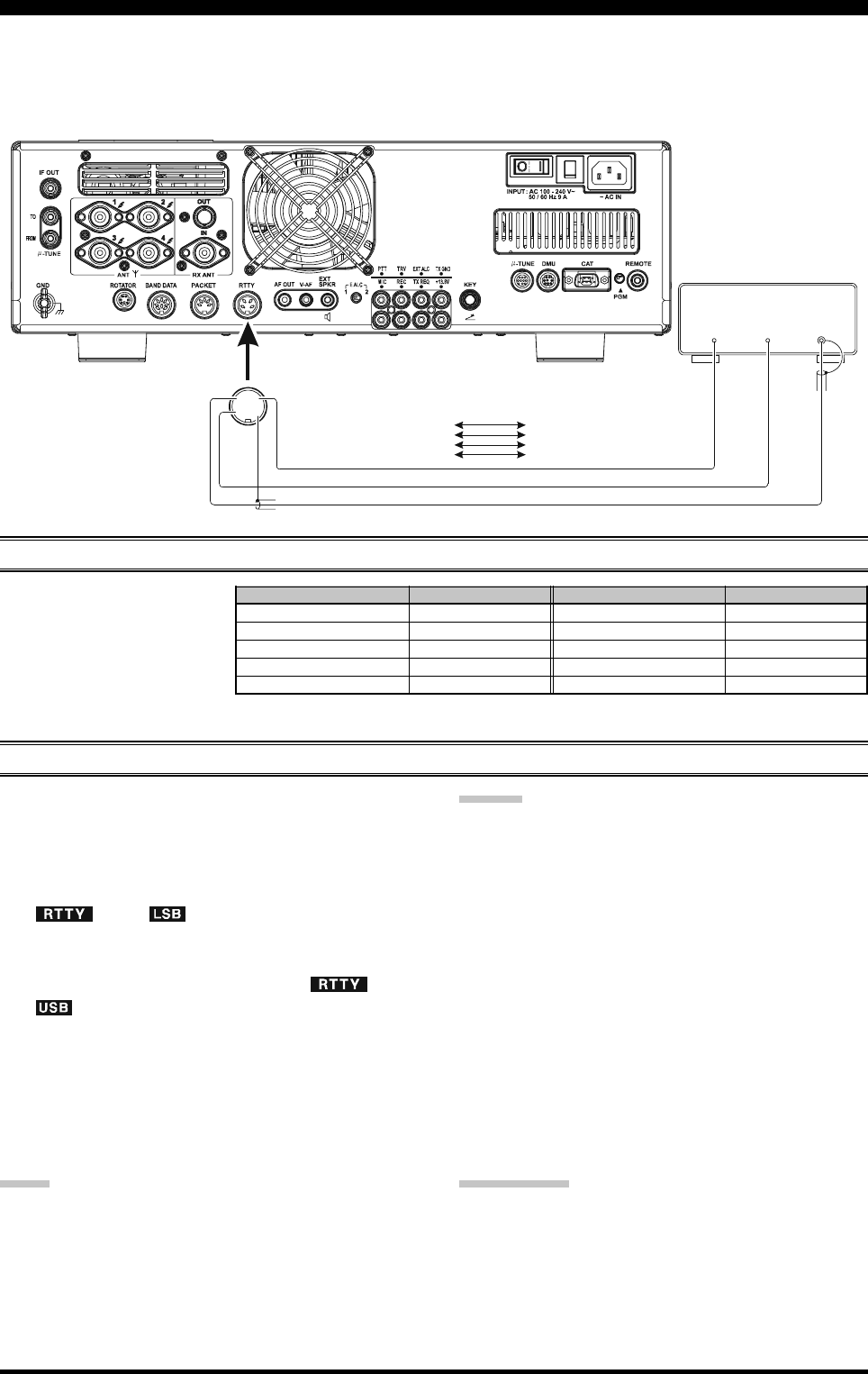
Page 111FTDX5000 OPERATING MANUAL
Most RTTY operation today is accomplished using a TNC or other computer-based system that utilizes AFSK tones. As
such, the previous discussion on LSB-mode “Packet” operation will also apply for Baudot operation. RTTY operation
using a Terminal Unit (TU), or the “FSK” output from a TNC is discussed below. Also, see the illustration for details
regarding connection to your TU.
SETTING UP FOR RTTY OPERATION
Before commencing RTTY op-
eration, please direct your atten-
tion to the setup steps shown in
the chart to the right.
BASIC SETUP
1. Press the [RTTY] button briefly, to enter the RTTY
mode.
One press of the [RTTY] button will engage RTTY
operation using “LSB” injection, which is generally
used in the Amateur service. In this mode, both the
“” and “ ” icons will appear in the dis-
play.
To switch to USB-side injection in RTTY, press the
[RTTY] button once more. Both the “ ” and
“” icons appear. Repeatedly pressing the [RTTY]
button will toggle between LSB and USB injection on
RTTY.
2. When you begin typing on your TU or computer key-
board, the command to transmit should automatically
be sent to the transceiver, causing it to enter the trans-
mit mode.
NOTE:
If you anticipate making data transmissions of longer than
a few minutes, we recommend that you use the [RF PWR]
knob to reduce the transmitter power to 1/2 ~ 1/3 of its
normal maximum.
RTTY (RADIO TELETYPE) OPERATION
FSK
OUT
PTT
FSK
IN
①④
③②
RTTY
RTTY JACK RTTY Machine
Pin 1 (SHIFT)
Pin 2
Pin 3
Pin 4
(RX OUT)
(PTT)
(GND)
FSK OUT
AF IN
PTT
GND
ADVICE:
The Mark/Space Shift utilized in most Amateur RTTY
operation is 170 Hz. Other shifts may be configured
using Menu item “097 RTTY SHIFT”.
The FTDX5000 is set up for “high tone” operation (cen-
tered on 2125 Hz) by default, but you may configure it
for low tone (1275 Hz) operation using Menu item “074
RTTY TONE”.
You may find that you are unable to decode some RTTY
stations, even if they are of sufficient signal strength.
If this is observed, there may be a Mark/Space polarity
problem between your station and the other station. If
so, try setting Menu item “093 RTTY R PLRTY” to
“REV” (“Reverse”) to see if that permits copy. A sepa-
rate Menu item permits reversal of your transmitter
Mark/Space polarity: “094 RTTY T PLRTY”.
QUICK POINT:
In the FTDX5000, “RTTY” is defined as an “FSK” mode,
whereby the closing and opening of a keying line (to
ground) causes the Mark/Space tones to alternate. The
RTTY mode is not an AFSK based mode in this trans-
ceiver and the AFSK output tones from a TNC will not
cause Mark/Space shifting to occur. Use the “Packet” mode
for AFSK-based Baudot and other data modes.
MENU ITEM
089 RTTY LCUT FRQ
090 RTTY LCUT SLP
091 RTTY HCUT FRQ
092 RTTY HCUT SLP
093 RTTY R PLRTY
AVAILABLE VALUES
OFF/100 ~ 1000 Hz
18dB/oct or 6dB/oct
OFF/700 ~ 4000 Hz
18dB/oct or 6dB/oct
NOR or REV
MENU ITEM
094 RTTY T PLRTY
095 RTTY RTTY OUT
096 RTTY OUT LEVEL
097 RTTY SHIFT
098 RTTY TONE
AVAILABLE VALUES
NOR or REV
VFO-A or VFO-B
0 ~ 100
170/200/425/850 Hz
1275/2125 Hz
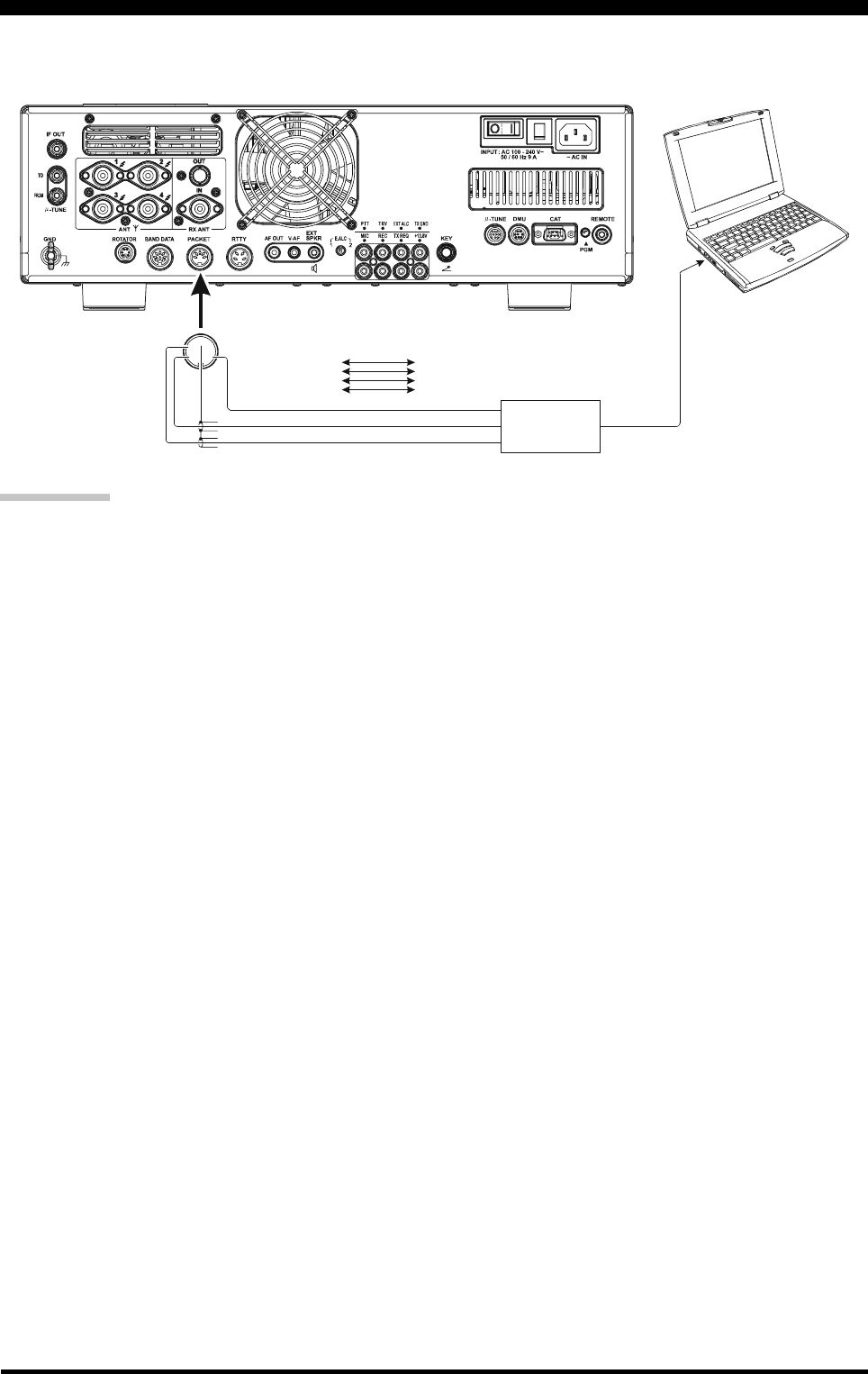
Page 112 FTDX5000 OPERATING MANUAL
MISCELLANEOUS AFSK-BASED DATA MODES
The FTDX5000 may also be used for a host of other SSB-based Data modes. Please set up your system using the illustration
as a guideline.
QUICK POINT:
When you have configured Menu item “174 TGEN VOX
SEL” to “DATA”, the transceiver will operate in a “VOX”
mode, and it is not necessary to connect a PTT line. This
makes very convenient to interface your transceiver to com-
puter Sound Cards, etc.
①
⑤④
③
②
PACKE T
Interface
DATA OUT
GND
PACKET PTT
DATA IN
LINE IN or MIC IN
LINE OUT or MIC OUT
COM PORT
Interface
PACK ET JACK
Pin 1 (DATA IN)
Pin 2
Pin 3
Pin 4
Pin 5
(GND)
(PACKET PTT)
(DATA OUT)
(BUSY)

Page 113FTDX5000 OPERATING MANUAL
NOTE
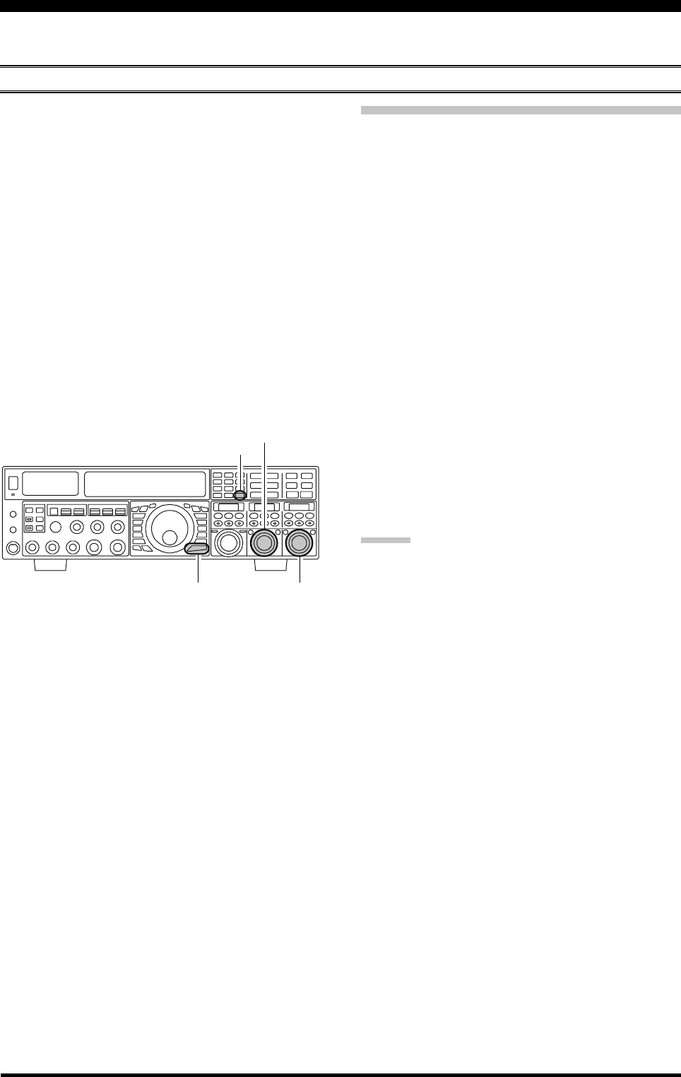
Page 114 FTDX5000 OPERATING MANUAL
You may connect an after-market transverter to the rear panel TRV jack. The output frequency is selectable from 14, 28,
and 50 MHz, and the output level is approximately –10 dBm (0.1 mW) at 50 Ohms.
SETUP
A
BOUT
THE
T
RANSVERTER
O
UTPUT
T
ERMINAL
1. Press the [MENU] button briefly to enter the Menu
mode.
2. Rotate the (VFO-A)[SELECT] knob to select Menu
item “150 TUNE MY BAND”.
3. Rotate the (VFO-B)[SELECT] knob to select the de-
sired input frequency band of the transverter in menu
item (T14M OFF, T28M OFF, or T50M OFF ).
4. Press the [ENT] button (one of the [BAND] buttons)
to change the parameter to “ON” (the “OFF” notation
will change to “ON”).
5. Rotate the (VFO-A)[SELECT] knob to select Menu
item “172 TGEN ETX-GND”.
6. Rotate the (VFO-B)[SELECT] knob to set this Menu
item to “ENABLE” to enable the internal relay con-
nected to the rear panel TX GND jack.
7. Press and hold the [MENU] button for at least two sec-
onds to save the new setting, and exit to normal opera-
tion.
Setting the Transverter Frequency Offset
You may set up the frequency display so that it shows the
frequencies of the transverter operating band (instead of
the 28 MHz band frequencies used as the “IF” on your
FTDX5000).
Example: Setting up the FTDX5000 display for use with a
144 MHz Transverter
1. Connect the 144 MHz transverter to the FTDX5000.
2. Press the [MENU] button briefly, to enter the Menu
mode.
3. Rotate the (VFO-A)[SELECT] knob to select the
Menu item which designates the input frequency band
from the transverter (040 GENE TRV 14M, 041
GENE TRV 28M, or 042 GENE TRV 50M).
4. Rotate the (VFO-B)[SELECT] knob to select
“44MHz” on the display.
5. Press and hold the [MENU] button in for at least two
seconds to save the new setting and exit.
The “100 MHz” digit of the frequency is not displayed,
so when you are operating on 2 meters and see “45
MHz” on the frequency readout, this indicates “145
MHz” instead.
ADVICE:
With the setup described above, tuning the actual operat-
ing range of the FTDX5000 will correspond to transverter
operating frequency of 144-145 MHz, with “44-45” being
displayed on the front panel of the transceiver.
(VFO-B)[SELECT] Knob
[MENU] Button
(VFO-A)[SELECT] Knob
[ENT] Button
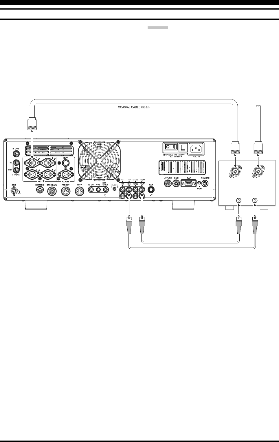
Page 115FTDX5000 OPERATING MANUAL
OPERATION
Transceiver V/U ANT
TX GND RF IN
T
X
G
N
D
T
R
V
V
H
F
/
U
H
F
A
n
t
e
n
n
a
A
BOUT
THE
T
RANSVERTER
O
UTPUT
T
ERMINAL
1. Set up the FTDX5000 for transverter use, as described
previously.
2. Choose the “Transverter” band with the “MY Bands”
procedures as described on page 46. You may find the
“Transverter” band between the “1.8 MHz” and “50
MHz” Bands.
3. Rotate the Main Tuning Dial knob to set the desired
operating frequency. Operation is basically unchanged
from normal transceiver operation.
ADVICE:
When the “Transverter” mode is turned on, TX power out-
put will not be allowed to pass to the “ANT 1” through
“ANT 4” main antenna jacks. So one of these may be con-
nected to your transverters “RX” jack. Just be certain to
disconnect the transverter when returning to HF opera-
tion, as the selected antenna jack will now be capable of
passing RF power.
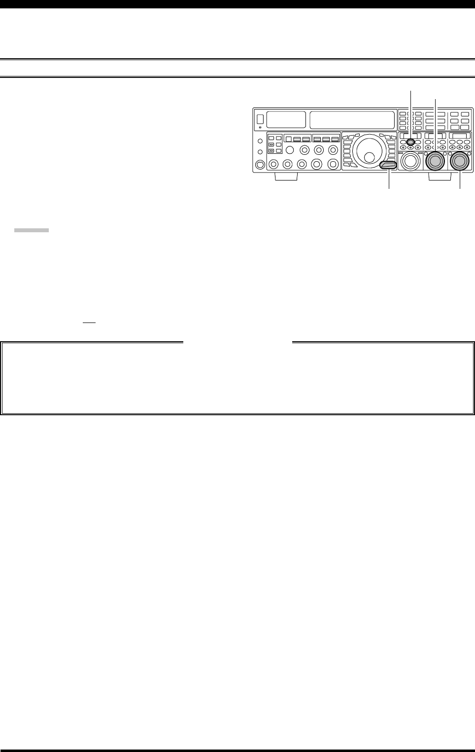
Page 116 FTDX5000 OPERATING MANUAL
MENU MODE
The Menu system of the FTDX5000 provides extensive customization capability, so you can set up your transceiver just the
way you want to operate it. The Menu items are grouped by general utilization category, and are numbered from “001 AGC
FST DLY” to “176 TGEN EMRGNCY.”
USING THE MENU
1. Press the [MENU] button momentarily, to engage the
Menu mode.
The SUB DISPLAY-I window will show the Menu
Number and Menu Group name, while the SUB DIS-
PLAY-II window will show the Menu item; the SUB
DISPLAY-III window shows the current setting of the
currently-selected Menu item.
2. Rotate the (VFO-A)[SELECT] knob to select the
Menu item you wish to work on.
3. Rotate the (VFO-B)[SELECT] knob to change the cur-
rent setting of the selected Menu item.
ADVICE:
Press the [CLEAR] button momentarily to reset the
selected Menu item to the factory default value.
4. When you have finished making your adjustments,
press and hold in the [MENU] button for two seconds
to save the new setting and exit to normal operation. If
you only momentarily press the [MENU] button, the
new settings will not be retained.
Menu Mode Reset
You may reset all the Menu settings to their original factory defaults, if desired.
1. Turn the front panel [POWER] switch off.
2. Press and hold in the [MENU] button, and while holding it in, press the [POWER] switch to turn the transceiver
back on. Now release the [MENU] button.
(VFO-B)[SELECT] Knob
[MENU] Button
(VFO-A)[SELECT] Knob
[CLEAR] Button

Page 117FTDX5000 OPERATING MANUAL
MENU MODE
GROUP NO. MENU FUNCTION AVAILABLE VALUES DEFAULT SETTING
AGC 001 AGC FST DLY 20 msec ~ 4000 msec (20 msec/step) 300 msec
AGC 002 AGC FST HLD 0 msec ~ 2000 msec (20 msec/step) 20 msec
AGC 003 AGC MID DLY 20 msec ~ 4000 msec (20 msec/step) 700 msec
AGC 004 AGC MID HLD 0 msec ~ 2000 msec (20 msec/step) 20 msec
AGC 005 AGC SLW DLY 20 msec ~ 4000 msec (20 msec/step) 3000 msec
AGC 006 AGC SLW HLD 0 msec ~ 2000 msec (20 msec/step) 20 msec
DISPLAY 007 DISP COLOR BLUE1 / BLUE2 / WHITE / UMBER1 / UMBER2 BLUE11
DISPLAY 008 DISP DIM MTR 0 ~ 15 8
DISPLAY 009 DISP DIM VFD 0 ~ 15 8
DISPLAY 010 DISP DIM OLE 0 ~ 15 8
DISPLAY 011 DISP DIM ELCD 0 ~ 15 8
DISPLAY 012 DISP BAR SEL CLAR / CW TUNE CW TUNE
DISPLAY 013 DISP S PK HLD OFF / 0.5s / 1.0s / 2.0s OFF
DISPLAY 014 DISP RTR STU 0° / 90° / 180° / 270° 0°
DISPLAY 015 DISP RTR ADJ –30° ~ 0° (2°/step) 0°
DISPLAY 016 DISP QMB MKR DISABLE / ENABLE ENABLE1
DISPLAY 017 DISP LVL IND PTCH / SPED / CDLY / VDLY / RPWR / ON
MICG / PROC
DISPLAY 018 DISP INDI VFD / OEL VFD
DISPLAY 019 DISP SELECT PTN1 / PTN2 / PTN3 PTN2
DVS 020 DVS RX LVL 0 ~ 100 50
DVS 021 DVS TX LVL 0 ~ 100 50
KEYER 022 KEY BEACON OFF / 1s ~ 255s OFF
KEYER 023 KEY NUM STL 1290 / AUNO / AUNT / A2NO / A2NT / 12NO / 12NT 1290
KEYER 024 KEY CONTEST 0 ~ 9999 1
KEYER 025 KEY CW MEM1 TEXT / MESSAGE MESSAGE
KEYER 026 KEY CW MEM2 TEXT / MESSAGE MESSAGE
KEYER 027 KEY CW MEM3 TEXT / MESSAGE MESSAGE
KEYER 028 KEY CW MEM4 TEXT / MESSAGE MESSAGE
KEYER 029 KEY CW MEM5 TEXT / MESSAGE MESSAGE
GENERAL 030 GENE ANT SEL BAND / STACK BAND
GENERAL 031 GENE BEEP LVL 0 ~ 100 40
GENERAL 032 GENE CAT BPS 4800 bps / 9600 bps / 19200 bps / 38400 bps 4800 bps
GENERAL 033 GENE CAT TOT 10 msec / 100 msec / 1000 msec / 3000 msec 10 msec
GENERAL 034 GENE CAT RTS DISABLE / ENABLE ENABLE
GENERAL 035 GENE CAT IND DISABLE / ENABLE ENABLE
GENERAL 036 GENE MEM GRP DISABLE / ENABLE DISABLE
GENERAL 037 GENE Q SPLIT –20 kHz ~ 0 kHz ~ 20 kHz (1 kHz/step) +5 kHz
GENERAL 038 GENE TRACK OFF / BAND / FREQ OFF
GENERAL 039 GENE TX TOT OFF / 1 ~ 30 min OFF
GENERAL 040 GENE TRV 14M 30 MHz ~ 46 MHz 44 MHz
GENERAL 041 GENE TRV 28M 30 MHz ~ 46 MHz 44 MHz
GENERAL 042 GENE TRV 50M 30 MHz ~ 46 MHz 44 MHz
GENERAL 043 GENE µT DIAL STEP-1 / STEP-2 / OFF STEP-1
GENERAL 044 GENE MIC SCN DISABLE / ENABLE ENABLE
GENERAL 045 GENE SCN RSM TIME / PAUSE TIME
GENERAL 046 GEnE FRQ ADJ –25 ~ 0 ~ +25 0
MODE-AM 047 A3E LCUT FRQ OFF / 100 Hz ~ 1000 Hz (50 Hz/step) OFF
MODE-AM 048 A3E LCUT SLP 6dB/oct or 18dB/oct 6dB/oct
MODE-AM 049 A3E HCUT FRQ 700 Hz ~ 4000 Hz / OFF (50 Hz/step) OFF
MODE-AM 050 A3E HCUT SLP 6dB/oct or 18dB/oct 6dB/oct
MODE-AM 051 A3E MIC GAIN MCVR / 0 ~ 100 30
MODE-AM 052 A3E MIC SEL FRONT / DATA / PC FRONT
: Requires optional DMU-2000 Data Management Unit.

Page 118 FTDX5000 OPERATING MANUAL
GROUP NO. MENU FUNCTION AVAILABLE VALUES DEFAULT SETTING
MODE-CW 053 A1A LCUT FRQ OFF / 100 Hz ~ 1000 Hz (50 Hz/step) 300 Hz
MODE-CW 054 A1A LCUT SLP 6dB/oct or 18dB/oct 18dB/oct
MODE-CW 055 A1A HCUT FRQ 700 Hz ~ 4000 Hz / OFF (50 Hz/step) 1000 Hz
MODE-CW 056 A1A HCUT SLP 6dB/oct or 18dB/oct 6dB/oct
MODE-CW 057 A1A F-TYPE OFF / BUG / ELEKEY / ACS ELEKEY
MODE-CW 058 A1A F-REV NOR / REV NOR
MODE-CW 059 A1A R-TYPE OFF / BUG / ELEKEY / ACS ELEKEY
MODE-CW 060 A1A R-REV NOR / REV NOR
MODE-CW 061 A1A CW AUTO OFF / 50M / ON OFF
MODE-CW 062 A1A BFO USB / LSB / AUTO USB
MODE-CW 063 A1A BK-IN SEMI / FULL SEMI
MODE-CW 064 A1A SHAPE 1 msec / 2 msec / 4 msec / 6 msec 4 msec
MODE-CW 065 A1A WEIGHT (1:) 2.5 ~ 4.5 3.0
MODE-CW 066 A1A FRQ DISP FREQ / PITCH PITCH
MODE-CW 067 A1A PC KYNG DISABLE / ENABLE DISABLE
MODE-CW 068 A1A QSKTIME 15 msec / 20 msec / 25 msec / 30 msec 15 msec
MODE-DAT 069 DATA DATA IN DATA / PC DATA
MODE-DAT 070 DADA DT GAIN 0 ~ 100 50
MODE-DAT 071 DATA DT OUT VFO-A / VFO-B VFO-A
MODE-DAT 072 DATA OUT LVL 0 ~ 100 50
MODE-DAT 073 DATA VOX DLY 30 ms ~ 3000 ms (10 ms/step) 300ms
MODE-DAT 074 DATA VOX GAIN 0 ~ 100 50
MODE-FM 075 F3E LCUT FRQ OFF / 100 Hz ~ 1000 Hz (50 Hz/step) OFF
MODE-FM 076 F3E LCUT SLP 6dB/oct or 18dB/oct 6dB/oct
MODE-FM 077 F3E HCUT FRQ 700 Hz ~ 4000 Hz / OFF (50 Hz/step) OFF
MODE-FM 078 F3E HCUT SLP 6dB/oct or 18dB/oct 6dB/oct
MODE-FM 079 F3E MIC GAIN MCVR / 0 ~ 100 50
MODE-FM 080 F3E MIC SEL FRONT / DATA / PC FRONT
MODE-FM 081 F3E 28 RPT 0 kHz ~ 1000 kHz (10 kHz/step) 100 kHz
MODE-FM 082 F3E 50 RPT 0 kHz ~ 4000 kHz (10 kHz/step) 1000 kHz
MODE-PKT 083 PKT LCUT FRQ OFF / 100 Hz ~ 1000 Hz (50 Hz/step) 300 Hz
MODE-PKT 084 PKT LCUT SLP 6dB/oct or 18dB/oct 18dB/oct
MODE-PKT 085 PKT HCUT FRQ 700 Hz ~ 4000 Hz / OFF (50 Hz/step) 3000 Hz
MODE-PKT 086 PKT HCUT SLP 6dB/oct or 18dB/oct 18dB/oct
MODE-PKT 087 PKT PKT DISP –3000 Hz ~ 3000 Hz (10 Hz/step) 0 Hz
MODE-PKT 088 PKT PKT SFT –3000 Hz ~ 3000 Hz (10 Hz/step) 1000 Hz
MODE-RTY 089 RTTY LCUT FRQ OFF / 100 Hz ~ 1000 Hz (50 Hz/step) 300 Hz
MODE-RTY 090 RTTY LCUT SLP 6dB/oct or 18dB/oct 18dB/oct
MODE-RTY 091 RTTY HCUT FRQ 700 Hz ~ 4000 Hz / OFF (50 Hz/step) 3000 Hz
MODE-RTY 092 RTTY HCUT SLP 6dB/oct or 18dB/oct 18dB/oct
MODE-RTY 093 RTTY R PLRTY NOR / REV NOR
MODE-RTY 094 RTTY T PLRTY NOR / REV NOR
MODE-RTY 095 RTTY RTTY OUT VFO-A / VFO-B VFO-A
MODE-RTY 096 RTTY OUT LVL 0 ~ 100 50
MODE-RTY 097 RTTY SHIFT 170 Hz / 200 Hz / 425 Hz / 850 Hz 170 Hz
MODE-RTY 098 RTTY TONE 1275 Hz / 2125 Hz 2125 Hz
MODE-SSB 099 A3J LCUT FRQ OFF / 100 Hz ~ 1000 Hz (50 Hz/step) 100 Hz
MODE-SSB 100 A3J LCUT SLP 6dB/oct or 18dB/oct 6dB/oct
MODE-SSB 101 A3J HCUT FRQ 700 Hz ~ 4000 Hz / OFF (50 Hz/step) 3000 Hz
MODE-SSB 102 A3J HCUT SLP 6dB/oct or 18dB/oct 6dB/oct
MODE-SSB 103 A3J MIC SEL FRONT / DATA / PC FRONT
MODE-SSB 104 A3J TX BPF 50-3000 / 100-2900 / 200-2800 / 300-2700 / 300-2700
400-2600 / 3000WB
MODE-SSB 105 A3J LSB CAR –200 Hz ~ 200 Hz (10 Hz/step) 0 Hz
MODE-SSB 106 A3J USB CAR –200 Hz ~ 200 Hz (10 Hz/step) 0 Hz
MENU MODE

Page 119FTDX5000 OPERATING MANUAL
GROUP NO. MENU FUNCTION AVAILABLE VALUES DEFAULT SETTING
RX AUDIO 107 ROUT AGC SLP NORMAL / SLOPE NORMAL
RX AUDIO 108 ROUT HEADPHN SEPARATE / COMBINE1 / COMBINE2 SEPARATE
RX GNRL 109 RGEN IF OUT DISABLE / ENABLE DISABLE
RX GNRL 110 RGEN MNB LVL 0 ~ 100 50
RX GNRL 111 RGEN MNB WDTH 0 ~ 100 50
RX DSP 112 RDSP CNTR LV –40 dB ~ 20 dB –15 dB
RX DSP 113 RDSP CNTR WI 1 ~ 11 10
RX DSP 114 RDSP NOTCH WI NARROW / WIDE WIDE
RX DSP 115 RDSP HCW SHP SOFT / SHARP SHARP
RX DSP 116 RDSP HCW SLP STEEP / MEDIUM / GENTLE MEDIUM
RX DSP 117 RDSP HPKT SHP SOFT / SHARP SHARP
RX DSP 118 RDSP HPKT SLP STEEP / MEDIUM / GENTLE MEDIUM
RX DSP 119 RDSP HRTY SHP SOFT / SHARP SHARP
RX DSP 120 RDSP HRTY SLP STEEP / MEDIUM / GENTLE MEDIUM
RX DSP 121 RDSP HSSB SHP SOFT / SHARP SHARP
RX DSP 122 RDSP HSSB SLP STEEP / MEDIUM / GENTLE MEDIUM
RX DSP 123 RDSP VCW SHP SOFT / SHARP SHARP
RX DSP 124 RDSP VCW SLP STEEP / MEDIUM / GENTLE MEDIUM
RX DSP 125 RDSP VPKT SHP SOFT / SHARP SHARP
RX DSP 126 RDSP VPKT SLP STEEP / MEDIUM / GENTLE MEDIUM
RX DSP 127 RDSP VRTY SHP SOFT / SHARP SHARP
RX DSP 128 RDSP VRTY SLP STEEP / MEDIUM / GENTLE MEDIUM
RX DSP 129 RDSP VSSB SHP SOFT / SHARP SHARP
RX DSP 130 RDSP VSSB SLP STEEP / MEDIUM / GENTLE MEDIUM
SCOPE 131 SCP 1.8 FIX 1800 kHz ~ 1999 kHz (1 kHz/step) 1800 kHz1
SCOPE 132 SCP 3.5 FIX 3500 kHz ~ 3999 kHz (1 kHz/step) 35000 kHz1
SCOPE 133 SCP 5.0 FIX 5250 kHz ~ 5499 kHz (1 kHz/step) 5250 kHz1
SCOPE 134 SCP 7.0 FIX 7000 kHz ~ 7299 kHz (1 kHz/step) 7000 kHz1
SCOPE 135 SCP 10.1 FIX 10100 kHz ~ 10149 kHz (1 kHz/step) 10100 kHz1
SCOPE 136 SCP 14.0 FIX 14000 kHz ~ 14349 kHz (1 kHz/step) 14000 kHz1
SCOPE 137 SCP 18.0 FIX 18000 kHz ~ 18199 kHz (1 kHz/step) 18068 kHz1
SCOPE 138 SCP 21.0 FIX 21000 kHz ~ 21449 kHz (1 kHz/step) 21000 kHz1
SCOPE 139 SCP 24.8 FIX 24800 kHz ~ 24989 kHz (1 kHz/step) 24890 kHz1
SCOPE 140 SCP 28.0 FIX 28000 kHz ~ 29699 kHz (1 kHz/step) 28000 kHz1
SCOPE 141 SCP 50.0 FIX 50000 kHz ~ 53999 kHz (1 kHz/step) 50000 kHz1
TUNING 142 TUN DIAL STP 1 Hz / 5 Hz / 10 Hz 10 Hz
TUNING 143 TUN CW FINE DISABLE / ENABLE DISABLE
TUNING 144 TUN MHz SEL 1 MHz / 100 kHz 100 kHz
TUNING 145 TUN AM STEP 2.5 kHz / 5 kHz / 9 kHz / 10 kHz / 12.5 kHz 5 kHz
TUNING 146 TUN FM STEP 5 kHz / 6.25 kHz / 10 kHz / 12.5 kHz / 5 kHz
20 kHz / 25 kHz
TUNING 147 TUN AM D.LCK DISABLE / ENABLE DISABLE
TUNING 148 TUN FM D.LCK DISABLE / ENABLE DISABLE
TUNING 149 TUN FM DIAL 10 Hz / 100 Hz 100 Hz
TUNING 150 TUN MY BAND 1.8M ~ 50M / GEN / T14M / T28M / T50M TRV
1: Requires optional DMU-2000 Data Management Unit.
2: This Menu item does not work. Please do not change this setting.
MENU MODE

Page 120 FTDX5000 OPERATING MANUAL
GROUP NO. MENU FUNCTION AVAILABLE VALUES DEFAULT SETTING
TX AUDIO 151 TAUD EQ1 FRQ OFF / 100 Hz ~ 700 Hz (100 Hz/step) OFF
TX AUDIO 152 TAUD EQ1 LVL –20 ~ 10 5
TX AUDIO 153 TAUD EQ1 BW 1 ~ 10 10
TX AUDIO 154 TAUD EQ2 FRQ OFF / 700 Hz ~ 1500 Hz (100 Hz/step) OFF
TX AUDIO 155 TAUD EQ2 LVL –20 ~ 10 5
TX AUDIO 156 TAUD EQ2 BW 1 ~ 10 10
TX AUDIO 157 TAUD EQ3 FRQ OFF / 1500 Hz ~ 3200 Hz (100 Hz/step) OFF
TX AUDIO 158 TAUD EQ3 LVL –20 ~ 10 5
TX AUDIO 159 TAUD EQ3 BW 1 ~ 10 10
TX AUDIO 160 TAUD PE1 FRQ OFF / 100 Hz ~ 700 Hz (100 Hz/step) 200 Hz
TX AUDIO 161 TAUD PE1 LVL –20 ~ 10 0
TX AUDIO 162 TAUD PE1 BW 1 ~ 10 2
TX AUDIO 163 TAUD PE2 FRQ OFF / 700 Hz ~ 1500 Hz (100 Hz/step) 800 Hz
TX AUDIO 164 TAUD PE2 LVL –20 ~ 10 0
TX AUDIO 165 TAUD PE2 BW 1 ~ 10 1
TX AUDIO 166 TAUD PE3 FRQ OFF / 1500 Hz ~ 3200 Hz (100 Hz/step) 2100 Hz
TX AUDIO 167 TAUD PE3 LVL –20 ~ 10 0
TX AUDIO 168 TAUD PE3 BW 1 ~ 10 1
TX GNRL 169 TGEN BIAS 1 ~ 100 100
TX GNRL 170 TGEN MAX PWR 20 W / 50 W / 100 W / 200 W 200 W
TX GNRL 171 TGEN PWR CTRL ALL MODE / CARRIER ALL MODE
TX GNRL 172 TGEN ETX-GND DISABLE / ENABLE DISABLE
TX GNRL 173 TGEN TUN PWR 20 W / 50 W / 100 W / 200 W 100 W
TX GNRL 174 TGEN VOX SEL MIC / DATA MIC
TX GNRL 175 TGEN ANTI VOX 0 ~ 100 50
TX GNRL 176 TGEN EMRGNCY DISABLE / ENABLE DISABLE
MENU MODE

Page 121FTDX5000 OPERATING MANUAL
AGC GROUP
001 AGC FST DLY
Function: Sets the delay time for the AGC FAST mode.
Available Values: 20 msec ~ 4000 msec (20 msec/step)
Default Setting: 300 msec
002 AGC FST HLD
Function: Sets the hang time of the AGC peak voltage for
the AGC FAST mode.
Available Values: 0 msec ~ 2000 msec (20 msec/step)
Default Setting: 20 msec
003 AGC MID DLY
Function: Sets the delay time for the AGC MID mode.
Available Values: 20 msec ~ 4000 msec (20 msec/step)
Default Setting: 700 msec
004 AGC MID HLD
Function: Sets the hang time of the AGC peak voltage for
the AGC MID mode.
Available Values: 0 msec ~ 2000 msec (20 msec/step)
Default Setting: 20 msec
005 AG SLW DLY
Function: Sets the delay time for the AGC SLOW mode.
Available Values: 20 msec ~ 4000 msec (20 msec/step)
Default Setting: 3000 msec
006 AGC SLW HLD
Function: Sets the hang time of the AGC peak voltage for
the AGC SLOW mode.
Available Values: 0 msec ~ 2000 msec (20 msec/step)
Default Setting: 20 msec
DISPLAY GROUP
007 DISP COLOR
Function: Selects the Display color when the optional Data
Management Unit (DMU-2000) is connected.
Available Values: BLUE1 / BLUE2 / WHITE /
UMBER1 / UMBER2
Default Setting: BLUE1
ADVICE:
If the optional DMU-2000 Data Management Unit is not
connected, this adjustment has no effect.
008 DISP DIM MTR
Function: Setting of the meter brightness level when
“DIM” is selected.
Available Values: 0 ~ 15
Default Setting: 8
009 DISP DIM VFD
Function: Setting of the frequency display brightness level
when “DIM” is selected.
Available Values: 0 ~ 15
Default Setting: 8
010 DISP DIM OEL
Function: Setting of three Sub Displays brightness level
when “DIM” is selected.
Available Values: 0 ~ 15
Default Setting: 8
011 DISP DIM ELCD
Function: Setting of the Spectrum Scope display bright-
ness level of the optional SM-5000 Station Monitor when
“DIM” is selected.
Available Values: 0 ~ 15
Default Setting: 8
ADVICE:
If the optional SM-5000 Station Monitor is not connected,
this adjustment has no effect.
012 DISP BAR SEL
Function: Selects one of three parameters to be viewed
on the Tuning Offset Indicator.
Available Values: CLAR / CW TUNE
Default Setting: CW TUNE
CLAR: Displays relative clarifier offset.
CW-TUNE: Displays relative CW tuning offset be-
tween the incoming signal and transmit-
ted frequency.
013 DISP PK HLD
Function: Selects the peak hold time of the VFO-B
receiver’s S-meter.
Available Values: OFF / 0.5s / 1.0s / 2.0s
Default Setting: OFF
MENU MODE
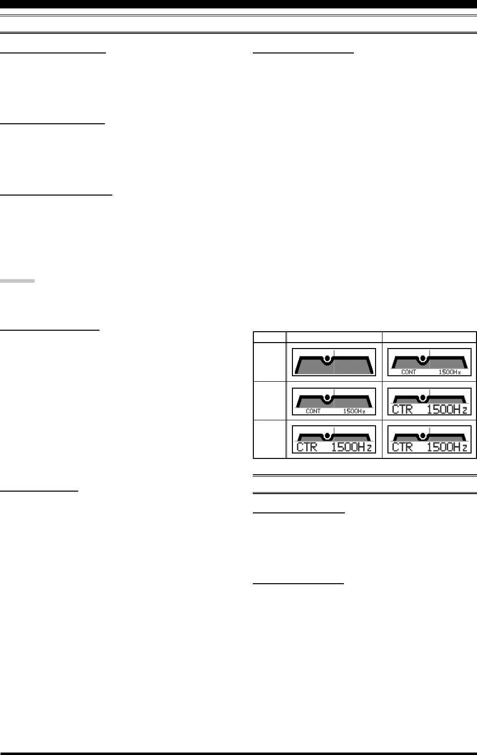
Page 122 FTDX5000 OPERATING MANUAL
014 DISP RTR STU
Function: Selects the starting point of your rotator
controller’s indicator needle.
Available Values: 0° / 90° / 180° / 270°
Default Setting: 0°
015 DISP RTR ADJ
Function: Adjusts the indicator needle precisely to the
starting point set in menu item “014 DISP RTR STU”.
Available Values: –30° ~ 0° (2°/step)
Default Setting: 0°
016 DISP QMB MKR
Function: Enables/Disables the QMB Marker (White ar-
row “”) to display on the Spectrum Band Scope when
the optional DMU-2000 Data Management Unit is con-
nected.
Available Values: DISABLE / ENABLE
Default Setting: ENABLE
ADVICE:
If the optional DMU-2000 Data Management Unit is not
connected, this adjustment has no effect.
017 DISP LVL IND
Function: Enables/Disables the Main Display to show the
frequency or value while each enabled knob is turned.
Available Values: PTCH (PITCH) / SPED (SPEED) /
CDLY (CW DELAY) / VDLY (VOX DEALAY) / RPWR
(RF POWER) / MICG (MIC GAIN) / PROC (PROCES-
SOR GAIN)
To disable the “function,” rotate the (VFO-B)[SELECT]
knob to recall the “function” to be disabled, then press the
[ENT] key (one of the [BAND] buttons) to change this
setting to “OFF”. Repeat the same procedures to enable a
function (setting it to “ON”).
018 DISP INDI
Function: Select the indicator location of the current value
when adjusting the following knobs.
Available Values: VFD / OEL
Default Setting: VFD
VFD: The current value will show for 3-seconds in the
lower right corner of the Main Display when-
ever the following knob is turned.
OEL: The current value will show for 3-seconds in the
SUB DISPLAY-III window whenever the fol-
lowing knob is turned.
:MIC, RF PWR, SPEED, PITCH, DELAY, and
PITCH knob
DISPLAY GROUP
019 DISP SELECT
Function: Selects the display pattern of the SUB DIS-
PLAY-II and SUB DISPLAY-III windows.
Available Values: PTN1 / PTN2 / PTN3
Default Setting: PTN2
PTN1: Generally, the current value is not indicated in
the window, only the graphic is depicted. When
the [SELECT] knob is rotated, the current
value will appear under the graphical display.
Three seconds after the turning of the [SE-
LECT] knob is stopped, the current value in-
dication disappears.
PTN2: Generally, the current value is indicated with
the small characters and graphical display.
When the [SELECT] knob is rotated, the cur-
rent value indication becomes large characters.
Three seconds after the turning of the [SE-
LECT] knob is stopped, the current value in-
dication returns to small characters.
PTN3: The current value always indicated with the
large characters and graphical display.
MENU MODE
DVS GROUP
020 DVS RX LVL
Function: Sets the audio output level from the voice
memory.
Available Values: 0 ~ 100
Default: 50
021 DVS TX LVL
Function: Sets the microphone input level to the voice
memory
Available Values: 0 ~ 100
Default: 50
PTN1
PTN2
PTN3
GENERAL WHILE ADJUSTING
SUB DISPLAY EXAMPLES (CONTOUR OPERATION)

Page 123FTDX5000 OPERATING MANUAL
KEYER GROUP
026 KEY CW MEM2
Function: Permits entry of the CW message for message
register 2.
Available Values: TEXT / MESSAGE
Default Setting: MESSAGE
TEXT: You may enter the CW message from the
FH-2’s keypad.
MESSAGE: You may enter the CW message from the
CW keyer.
027 KEY CW MEM3
Function: Permits entry of the CW message for message
register 3.
Available Values: TEXT / MESSAGE
Default Setting: MESSAGE
TEXT: You may enter the CW message from the
FH-2’s keypad.
MESSAGE: You may enter the CW message from the
CW keyer.
028 KEY CW MEM4
Function: Permits entry of the CW message for message
register 4.
Available Values: TEXT / MESSAGE
Default Setting: MESSAGE
TEXT: You may enter the CW message from the
FH-2’s keypad.
MESSAGE: You may enter the CW message from the
CW keyer.
029 KEY CW MEM5
Function: Permits entry of the CW message for message
register 5.
Available Values: TEXT / MESSAGE
Default Setting: MESSAGE
TEXT: You may enter the CW message from the
FH-2’s keypad.
MESSAGE: You may enter the CW message from the
CW keyer.
MENU MODE
022 KEY BEACON
Function: Sets the interval time between repeats of the
beacon message.
Available Values: OFF / 1s ~ 255 sec
Default Setting: OFF
023 KEY NUM STL
Function: Selects the Contest Number “Cut” format for
an imbedded contest number.
Available Values: 1290 / AUNO / AUNT / A2NO / A2NT
/12NO / 12NT
Default Setting: 1290
1290: Does not abbreviate the Contest Number
AUNO: Abbreviates to “A” for “One,” “U” for “Two,”
“N” for “Nine,” and “O” for “Zero.”
AUNT: Abbreviates to “A” for “One,” “U” for “Two,”
“N” for “Nine,” and “T” for “Zero.”
A2NO: Abbreviates to “A” for “One,” “N” for “Nine,”
and “O” for “Zero.”
A2NT: Abbreviates to “A” for “One,” “N” for “Nine,”
and “T” for “Zero.”
12NO: Abbreviates to “N” for “Nine,” and “O” for
“Zero.”
12NT: Abbreviates to “N” for “Nine,” and “T” for
“Zero.”
024 KEY CONTEST
Function: Enters the initial contest number that will in-
crement/decrement after sending during contest QSOs.
Available Values: 0 ~ 9999
Default Setting: 1
ADVICE:
Press the [CLEAR] button to reset the contest number to
“1.”
025 KEY CW MEM1
Function: Permits entry of the CW message for message
register 1.
Available Values: TEXT / MESSAGE
Default Setting: MESSAGE
TEXT: You may enter the CW message from the
FH-2’s keypad.
MESSAGE: You may enter the CW message from the
CW keyer.

Page 124 FTDX5000 OPERATING MANUAL
GENERAL GROUP
038 GENE TRACK
Function: Sets the VFO Tracking feature.
Available Values: OFF / BAND / FREQ
Default Setting: OFF
OFF: Disables the VFO Tracking feature.
BAND: When you change bands on the VFO-A side,
the VFO-B will automatically change to be
the same as that of VFO-A.
FREQ: This function is the similar to “BAND”, addi-
tionally, the VFO-B frequency changes to-
gether with the VFO-A frequency when turn-
ing the Main Dial Tuning knob.
039 GENE TX TOT
Function: Sets the Time-Out Timer countdown time.
Available Values: OFF / 1min ~ 30min
Default Setting: OFF
The Time-Out Timer shuts off the transmitter after con-
tinuous transmission of the programmed time.
040 GENE TRV 14M
Function: Sets the 10’s and 1’s of the MHz digits display
for operation with a transverter when the exciter band is
14 MHz.
Available Values: 30 MHz ~ 46 MHz
Default Setting: 44 MHz
The default setting would be used with a 144 MHz
transverter. If you connect a 430 MHz transverter to the
radio, set this menu to “30” (the “100 MHz” digits are
hidden on this radio).
041 GENE TRV 28M
Function: Sets the 10’s and 1’s of the MHz digits display
for operation with a transverter when the exciter band is
28 MHz.
Available Values: 30 MHz ~ 46 MHz
Default Setting: 44 MHz
The default setting would be used with a 144 MHz
transverter. If you connect a 430 MHz transverter to the
radio, set this menu to “30” (the “100 MHz” digits are
hidden on this radio).
042 GENE TRV 50M
Function: Sets the 10’s and 1’s of the MHz digits display
for operation with a transverter when the exciter band is
50 MHz.
Available Values: 30 MHz ~ 46 MHz
Default Setting: 44 MHz
The default setting would be used with a 144 MHz
transverter. If you connect a 430 MHz transverter to the
radio, set this menu to “30” (the “100 MHz” digits are
hidden on this radio).
MENU MODE
030 GENE ANT SEL
Function: Sets the method of antenna selection.
Available Values: BAND / STACK
Default Setting: BAND
BAND: The antenna is selected in accordance with
the operating band.
STACK: The antenna is selected in accordance with
the band stack (different antennas may be uti-
lized on the same band, if so selected in the
band stack).
031 GENE BEEP LVL
Function: Sets the beep level.
Available Values: 0 ~ 100
Default Setting: 40
032 GENE CAT BPS
Function: Sets the transceiver’s computer-interface cir-
cuitry for the CAT baud rate to be used.
Available Values: 4800bps / 9600bps / 19200bps /
38400bps
Default Setting: 4800bps
033 GENE CAT TOT
Function: Sets the Time-Out Timer countdown time for a
CAT command input.
Available Values: 10ms / 100ms / 1000ms / 3000ms
Default Setting: 10ms
The Time-Out Timer shuts off the CAT data input after the
continuous transmission of the programmed time.
034 GENE CAT RTS
Function: Enables/Disables the RTS port of the CAT jack.
Available Values: DISABLE / ENABLE
Default Setting: ENABEL
035 GENE CAT IND
Function: Enables/Disables the flashing of the CAT LED
in conjunction with the CAT commands.
Available Values: DISABLE / ENABLE
Default Setting: ENABEL
036 GENE MEM GRP
Function: Enables/Disables Memory Group Operation.
Available Values: DISABLE / ENABLE
Default Setting: DISABEL
037 GENE Q SPLIT
Function: Selects the tuning offset for the Quick Split fea-
ture.
Available Values: –20 kHz ~ 0 kHz ~ 20 kHz (1 kHz Step)
Default Setting: 5 kHz

Page 125FTDX5000 OPERATING MANUAL
043 GENE µT DIAL
Function: Selects the µ-TUNE mode.
Available Values: STEP-1 / STEP-2 / OFF
Default Setting: STEP-1
STEP-1: Activates the µ-TUNE system using
“COARSE” steps of the [SELECT] knob (2
steps/click) on the 7 MHz and lower amateur
bands. On the 10/14 MHz bands, “FINE”
steps of [SELECT] knob (1 step/click) will
be used.
STEP-2: Activates the µ-TUNE system using “FINE”
steps of the [SELECT] knob (1 step/click)
on the 14 MHz and lower amateur bands on
the Main band (VFO-A).
OFF: Disables the µ-TUNE system. Activates the
VRF feature on the 14 MHz and lower ama-
teur bands on the main band (VFO-A).
ADVICE:
If the optional RF µTuning Kit is not connected, this ad-
justment has no effect.
044 GENE MIC SCN
Function: Enables/disables scanning access via the
microphone’s [UP]/[DWN] keys.
Available Values: DISABLE / ENABLE
Default Setting: ENABLE
045 GENE SCN RSM
Function: Selects the Scan Resume mode.
Available Values: TIME / PAUSE
Default Setting: TIME
TIME: The scanner will hold for five seconds, then
resume whether or not the other station is still
transmitting.
PAUSE: The scanner will hold until the signal disap-
pears, then will resume after one second.
046 GENE FRQ ADJ
Function: Adjusts the reference oscillator.
Available Values: –25 ~ 0 ~ 25
Default Setting: 0
Connect a 50-Ohm dummy load and frequency counter to
the antenna jack; adjust the (VFO-B)[SELECT] knob so
that the frequency counter reading is same as the VFO
frequency while pressing the PTT switch.
ADVICE:
Do not perform this Menu item unless you have a high-
performance frequency counter. Perform this Menu item
after aging the transceiver and frequency counter suffi-
ciently (at least 30 minutes).
MODE-AM GROUP
047 A3E LCUT FRQ
Function: Selects the cutoff frequency of the lower side
of the RX audio filter in the AM mode.
Available Values: OFF / 100 Hz ~ 1000Hz (50 Hz/step)
Default Setting: OFF
048 A3E LCUT SLP
Function: Selects the filter slope of the lower side of the
RX audio filter in the AM mode.
Available Values: 6dB/oct or 18dB/oct
Default Setting: 6dB/oct
049 A3E HCUT FRQ
Function: Selects the cutoff frequency of the upper side
of the RX audio filter in the AM mode.
Available Values: OFF / 700Hz ~ 4000Hz (50 Hz/step)
Default Setting: OFF
050 A3E HCUT SLP
Function: Selects the filter slope of the upper side of the
RX audio filter in the AM mode.
Available Values: 6dB/oct or 18dB/oct
Default Setting: 6dB/oct
051 A3E MIC GAIN
Function: Sets the microphone gain for the AM mode.
Available Values: MCVR / 0 ~ 100
Default Setting: 30
When this menu is set to “MCVR”, you may adjust the
microphone gain using the front panel’s [MIC] knob.
052 A3E MIC SEL
Function: Selects the microphone to be used in the AM
mode.
Available Values: FRONT / DATA / PC
Default Setting: FRONT
FRONT: Selects the microphone connected to the front
panel’s MIC jack while using the AM mode.
DATA: Selects the microphone connected to pin 1 of
the PACKET Jack while using the AM mode.
PC: This parameter is for future expansion of this
transceiver’s capabilities, but at this time is
not supported.
MENU MODE
GENERAL GROUP

Page 126 FTDX5000 OPERATING MANUAL
MODE-CW GROUP
059 A1A R-TYPE
Function: Selects the desired keyer operation mode for
the device connected to the rear panel KEY jack.
Available Values: OFF / BUG / ELEKEY / ACS
Default Setting: ELEKEY
OFF: Disables the rear panel keyer (use this mode
with a straight key, an external keyer, or a
computer-driven keying interface).
BUG: Mechanical “bug” keyer emulation. One
paddle produces “dits” automatically, while
the other paddle manually produces “dahs.”
ELEKEY: Iambic keyer with ACS (Automatic Char-
acter Spacing) disabled.
ACS: Iambic keyer with ACS (Automatic Char-
acter Spacing) enabled.
060 A1A R-REV
Function: Selects the keyer paddle wiring configuration
for the KEY jack on the rear panel.
Available Values: NOR / REV
Default Setting: nor
NOR: Tip = Dot, Ring = Dash, Shaft = Ground
REV: Tip = Dash, Ring = Dot, Shaft = Ground
061 A1A CW AUTO
Function: Enables/disables CW keying while operating
on SSB.
Available Values: OFF / 50M / ON
Default Setting: OFF
OFF: Disables CW keying while operating on SSB.
50M: Enables CW keying only while operating SSB
on 50 MHz (but not HF).
ON: Enables CW keying while operating on SSB (all
TX bands).
NOTE:
This feature allows you to move someone from SSB to
CW without having to change modes on the front panel.
062 A1A BFO
Function: Sets the CW carrier oscillator injection side for
the CW mode.
Available Values: USB / LSB / AUTO
Default Setting: USB
USB: Injects the CW carrier oscillator on the USB
side.
LSB: Injects the CW carrier oscillator on the LSB
side.
AUTO: Injects the CW carrier oscillator on the LSB
side while operating on the 7 MHz band and
below, and the USB side while operating on
the 10 MHz band and up.
MENU MODE
053 A1A LCUT FRQ
Function: Selects the cutoff frequency of the lower side
of the RX audio filter in the CW mode.
Available Values: OFF / 100 Hz ~ 1000Hz (50 Hz/step)
Default Setting: 300Hz
054 A1A LCUT SLP
Function: Selects the filter slope of the lower side of the
RX audio filter in the CW mode.
Available Values: 6dB/oct or 18dB/oct
Default Setting: 18dB/oct
055 A1A HCUT FRQ
Function: Selects the cutoff frequency of the upper side
of the RX audio filter in the CW mode.
Available Values: OFF / 700Hz ~ 4000Hz (50 Hz/step)
Default Setting: 1000Hz
056 A1A HCUT SLP
Function: Selects the filter slope of the upper side of the
RX audio filter in the CW mode.
Available Values: 6dB/oct or 18dB/oct
Default Setting: 6dB/oct
057 A1A F-TYPE
Function: Selects the desired keyer operation mode for
the device connected to the front panel KEY jack.
Available Values: OFF / BUG / ELEKEY / ACS
Default Setting: ELEKEY
OFF: Disables the front panel keyer (use this
mode with a straight key, an external keyer,
or a computer-driven keying interface).
BUG: Mechanical “bug” keyer emulation. One
paddle produces “dits” automatically, while
the other paddle manually produces “dahs.”
ELEKEY: Iambic keyer with ACS (Automatic Char-
acter Spacing) disabled.
ACS: Iambic keyer with ACS (Automatic Char-
acter Spacing) enabled.
058 A1A F-REV
Function: Selects the keyer paddle’s wiring configuration
for the KEY jack on the front panel.
Available Values: NOR / REV
Default Setting: nor
NOR: Tip = Dot, Ring = Dash, Shaft = Ground
REV: Tip = Dash, Ring = Dot, Shaft = Ground

Page 127FTDX5000 OPERATING MANUAL
063 A1A BK-IN
Function: Sets the CW “break-in” mode.
Available Values: SEMI / FULL
Default Setting: SEMI
SEMI: The transceiver will operate in the semi break-
in mode. The delay (receiver recovery) time is
set by the front panel [DELAY] knob.
FULL: The transceiver will operate in the full break-
in (QSK) mode.
064 A1A SHAPE
Function: Selects the CW carrier wave-form shape (rise/
fall times).
Available Values: 1ms / 2ms / 4ms / 6ms
Default Setting: 4 ms
065 A1A WEIGHT
Function: Sets the Dot:Dash ratio for the built-in elec-
tronic keyer.
Available Values: (1:) 2.5 ~ 4.5
Default Setting: 3.0
066 A1A FRQ DISP
Function: Selects the frequency Display Format for the
CW mode.
Available Values: FREQ / PITCH
Default Setting: PITCH
FREQ: Displays the receiver carrier frequency, with-
out any offset added. When changing modes
between SSB and CW, the frequency display
remains constant.
PITCH: This frequency display reflects the added
BFO offset.
067 A1A PC KYNG
Function: Enables/disables CW keying from the
“PACKET PTT” terminal (pin 3) on the rear panel’s
PACKET jack while operating in the CW mode.
Available Values: DISABLE / ENABLE
Default Setting: DISABLE
068 A1A QSK TIME
Function: Selects the time delay between when the PTT
is keyed and the carrier is transmitted during QSK opera-
tion when using the internal keyer.
Available Values: 15ms / 20ms / 25ms / 30 ms
Default Setting: 15ms
MODE-DAT GROUP
069 DATA DATA IN
Function: Selects the data input path to be used in the
PKT mode.
Available Values: DATA / PC
Default Setting: DATA
DATA: Uses the data input line connected to pin 1 of
the PACKET jack while using the PKT mode.
PC: This parameter is for future expansion of this
transceiver’s capabilities, but at this time is
not supported.
070 DATA DT GAIN
Function: Sets the data input level from the TNC to the
AFSK modulator.
Available Values: 0 ~ 100
Default Setting: 50
071 DATA DT OUT
Function: Selects the receiver to be connected to the data
output port (pin 4) of the PACKET jack.
Available Values: VFO-A / VFO-B
Default Setting: VFO-A
072 DATA OUT LVL
Function: Sets the AFSK data output level at the output
port (pin 4) of the PACKET jack.
Available Values: 0 ~ 100
Default Setting: 50
073 DATA VOX DLY
Function: Adjusts the “VOX” delay (receiver recovery)
time in the PKT mode.
Available Values: 30ms ~ 3000ms (10 ms/step)
Default Setting: 300ms
074 DATA VOX GAIN
Function: Adjusts the “VOX” gain in the PKT mode.
Available Values: 0 ~ 100
Default Setting: 50
MODE-CW GROUP
MENU MODE

Page 128 FTDX5000 OPERATING MANUAL
MODE-PKT GROUP
083 PKT LCUT FRQ
Function: Selects the cutoff frequency of the lower side
of the RX audio filter in the Packet mode.
Available Values: OFF / 100Hz ~ 1000Hz (50 Hz/step)
Default Setting: 300Hz
084 PKT LCUT SLP
Function: Selects the filter slope of the lower side of the
RX audio filter in the Packet mode.
Available Values: 6dB/oct or 18dB/oct
Default Setting: 18dB/oct
085 PKT HCUT FRQ
Function: Selects the cutoff frequency of the upper side
of the RX audio filter in the Packet mode.
Available Values: OFF / 700Hz ~ 4000Hz (50 Hz/step)
Default Setting: 3000Hz
086 PKT HCUT SLP
Function: Selects the filter slope of the upper side of the
RX audio filter in the Packet mode.
Available Values: 6dB/oct or 18dB/oct
Default Setting: 18dB/oct
087 PKT PKTDISP
Function: Sets the packet frequency display offset.
Available: –3000Hz ~ 3000Hz (10 Hz/step)
Default: 0Hz
088 DATA PKT SFT
Function: Sets the carrier point during the SSB packet
operation.
Available: –3000Hz ~ 3000Hz (10 Hz/step)
Default: 1000Hz (typical center frequency for PSK31, etc.)
MENU MODE
MODE-FM GROUP
075 F3E LCUT FRQ
Function: Selects the cutoff frequency of the lower side
of the RX audio filter in the FM mode.
Available Values: OFF / 100Hz ~ 1000Hz (50 Hz/step)
Default Setting: OFF
076 F3E LCUT SLP
Function: Selects the filter slope of the lower side of the
RX audio filter in the FM mode.
Available Values: 6dB/oct or 18dB/oct
Default Setting: 6dB/oct
077 F3E HCUT FRQ
Function: Selects the cutoff frequency of the upper side
of the RX audio filter in the FM mode.
Available Values: OFF / 700Hz ~ 4000Hz (50 Hz/step)
Default Setting: OFF
078 F3E HCUT SLP
Function: Selects the filter slope of the upper side of the
RX audio filter in the FM mode.
Available Values: 6dB/oct or 18dB/oct
Default Setting: 6dB/oct
079 F3E MIC GAIN
Function: Sets the microphone gain for the FM mode.
Available Values: MCVR / 0 ~ 100
Default Setting: 50
When this menu is set to “MCVR”, you may adjust the
microphone gain using the front panel [MIC] knob.
080 F3E MIC SEL
Function: Selects the microphone to be used on the FM
mode.
Available Values: FRONT / DATA / PC
Default Setting: FRONT
FRONT: Selects the microphone connected to the front
panel MIC jack while using the FM mode.
DATA: Selects the microphone connected to pin 1 of
the PACKET Jack while using the FM mode.
PC: This parameter is for future expansion of this
transceiver’s capabilities, but at this time is
not supported.
081 F3E 28 RPT
Function: Sets the magnitude of the repeater shift on the
28 MHz band.
Available Values: 0kHz ~ 1000kHz (10 kHz/step)
Default Setting: 100kHz
082 F3E 50 RPT
Function: Sets the magnitude of the repeater shift on the
50 MHz band.
Available Values: 0kHz ~ 4000kHz (10 kHz/step)
Default Setting: 1000kHz

Page 129FTDX5000 OPERATING MANUAL
MODE-RTY GROUP
089 RTTY LCUT FRQ
Function: Selects the cutoff frequency of the lower side
of the RX audio filter in the RTTY mode.
Available Values: OFF / 100Hz ~ 1000Hz (50 Hz/step)
Default Setting: 300Hz
090 RTTY LCUT SLP
Function: Selects the filter slope of the lower side of the
RX audio filter in the RTTY mode.
Available Values: 6dB/oct or 18dB/oct
Default Setting: 18dB/oct
091 RTTY HCUT FRQ
Function: Selects the cutoff frequency of the upper side
of the RX audio filter in the RTTY mode.
Available Values: OFF / 700Hz ~ 4000Hz (50 Hz/step)
Default Setting: 3000Hz
092 RTTY HCUT SLP
Function: Selects the filter slope of the upper side of the
RX audio filter in the RTTY mode.
Available Values: 6dB/oct or 18dB/oct
Default Setting: 18dB/oct
093 RTTY R PLRTY
Function: Selects normal or reverse Mark/Space polarity
for RTTY receive operation.
Available Values: NOR / REV
Default Setting: NOR
094 RTTY T PLRTY
Function: Selects normal or reverse Mark/Space polarity
for RTTY transmit operation.
Available Values: NOR / REV
Default Setting: NOR
095 RTTY RTTY OUT
Function: Selects the receiver to be connected to the data
output port (pin 2) of the RTTY jack.
Available Values: VFO-A / VFO-B
Default Setting: VFO-A
096 RTTY OUT LVL
Function: Sets the FSK RTTY data output level at the
output port (pin 2) of the RTTY jack.
Available Values: 0 ~ 100
Default Setting: 50
097 RTTY SHIFT
Function: Selects the frequency shift for FSK RTTY op-
eration.
Available Values:170Hz / 200Hz / 425Hz / 850Hz
Default Setting: 170Hz
098 RTTY TONE
Function: Selects the Mark tone for RTTY operation.
Available Values: 1275Hz / 2125Hz
Default Setting: 2125Hz
MENU MODE
MODE-SSB GROUP
099 A3J LCUT FRQ
Function: Selects the cutoff frequency of the lower side
of the RX audio filter in the SSB mode.
Available Values: OFF / 100Hz ~ 1000Hz (50 Hz/step)
Default Setting: 100Hz
100 A3J LCUT SLP
Function: Selects the filter slope of the lower side of the
RX audio filter in the SSB mode.
Available Values: 6dB/oct or 18dB/oct
Default Setting: 6dB/oct
101 A3J HCUT FRQ
Function: Selects the cutoff frequency of the upper side
of the RX audio filter in the SSB mode.
Available Values: OFF / 700Hz ~ 4000Hz (50 Hz/step)
Default Setting: 3000Hz
102 A3J HCUT SLP
Function: Selects the filter slope of the upper side of the
RX audio filter in the SSB mode.
Available Values: 6dB/oct or 18dB/oct
Default Setting: 6dB/oct
103 A3J MIC SEL
Function: Selects the microphone to be used on the SSB
modes (LSB and USB).
Available Values: FRONT / DATA / PC
Default Setting: Frnt
FRONT: Selects the microphone connected to the front
panel MIC jack while using the SSB modes.
DATA: Selects the microphone connected to pin 1 of
the PACKET Jack while using the SSB
modes.
PC: This parameter is for future expansion of this
transceiver’s capabilities, but at this time is
not supported.
104 A3J TX BPF
Function: Selects the audio passband of the DSP modula-
tor on the SSB mode.
Available Values: 50-3000 / 100-2900 / 200-2800 /
300-2700 / 400-2600 / 3000WB
Default Setting: 300-2700 (Hz)
NOTE:
The apparent power output, when using the widest band-
widths, may seem lower. This is normal, and it occurs be-
cause the available transmitter power is distributed over a
wider bandwidth. The greatest compression of power out-
put, conversely, occurs when using the “400-2600” set-
ting (400-2600 Hz), and this setting is highly recommended
for contest or DX pile-up work.
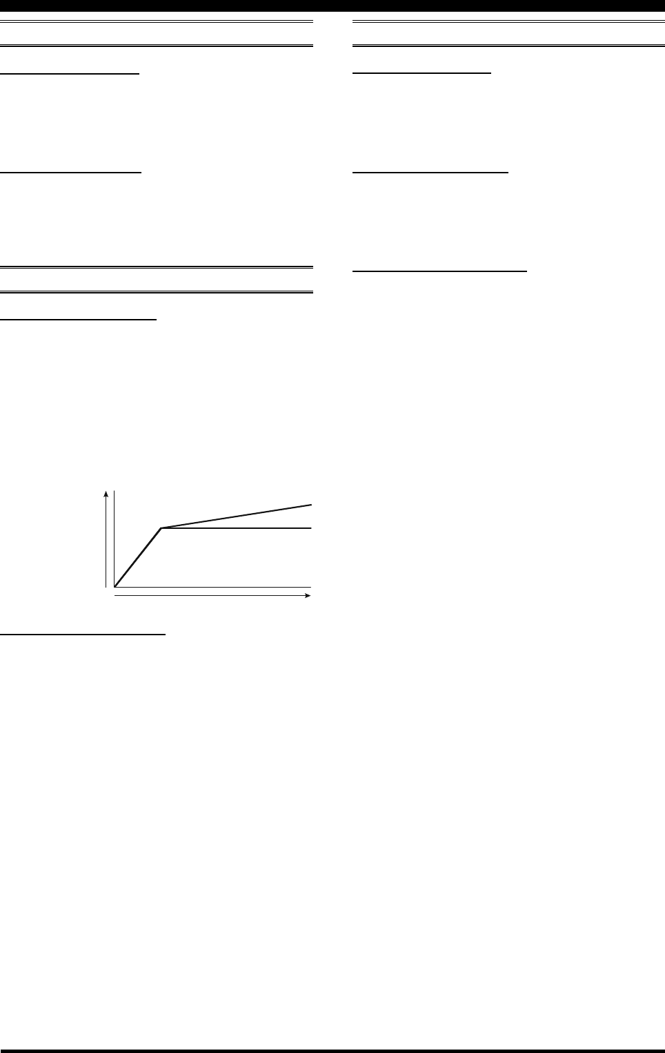
Page 130 FTDX5000 OPERATING MANUAL
MENU MODE
108 ROUT HEADPHN
Function: Selects one of three audio mixing modes when
using headphones during Dual Receive operation.
Available Values: SEPARATE / COMBINE1 /
COMBINE2
Default Setting: SEPARATE
SEPARATE: Audio from the VFO-A receiver
is heard only in the left ear, and
VFO-B receiver audio solely in
the right ear.
COMBINE1: Audio from both VFO-A and
VFO-B receivers can be heard
in both ears, but VFO-B audio
is attenuated in the left ear and
VFO-A audio is attenuated in
the right ear.
COMBINE2: Audio from both VFO-A and
VFO-B receivers is combined
and heard equally in both ears.
105 A3J LSB CAR
Function: Adjusts the receiver carrier point for the LSB
mode.
Available Values: –200 Hz ~ 200 Hz (10 Hz/steps)
Default Setting: 0 Hz
106 A3J USB CAR
Function: Adjusts the receiver carrier point for the USB
mode.
Available Values: –200 Hz ~ 200 Hz (10 Hz/step)
Default Setting: 0 Hz
RX AUDIO GROUP
107 ROUT AGC SLP
Function: Selects the gain curve of the AGC amplifier.
Available Values: NORMAL / SLOPE
Default Setting: nor
NORMAL: The AGC output level will follow a lin-
ear response to the antenna input level,
while AGC is activated.
SLOPE: The AGC output level will increase at 1/
10 the rate of the antenna input level,
while AGC is activated.
NORMAL
Input Signal
A
u
d
i
o
O
u
t
p
u
t
SLOPE
MODE-SSB GROUP RX GNRL GROUP
109 RGEN IF OUT
Function: Enables/Disables the 9 MHz RX IF signal from
the rear panel IF OUT jack.
Available Values: DISABLE / ENABLE
Default Setting: DISABLE
110 RGEN MNB LVL
Function: Adjusts the noise blanking level of the VFO-A
IF noise Blanker.
Available Values: 0 ~ 100
Default Setting: 50
111 RGEN MNB WDTH
Function: Adjusts the bandwidth for the longer-duration
pulse noise of the VFO-A IF noise Blanker.
Available Values: 0 ~ 100
Default Setting: 50
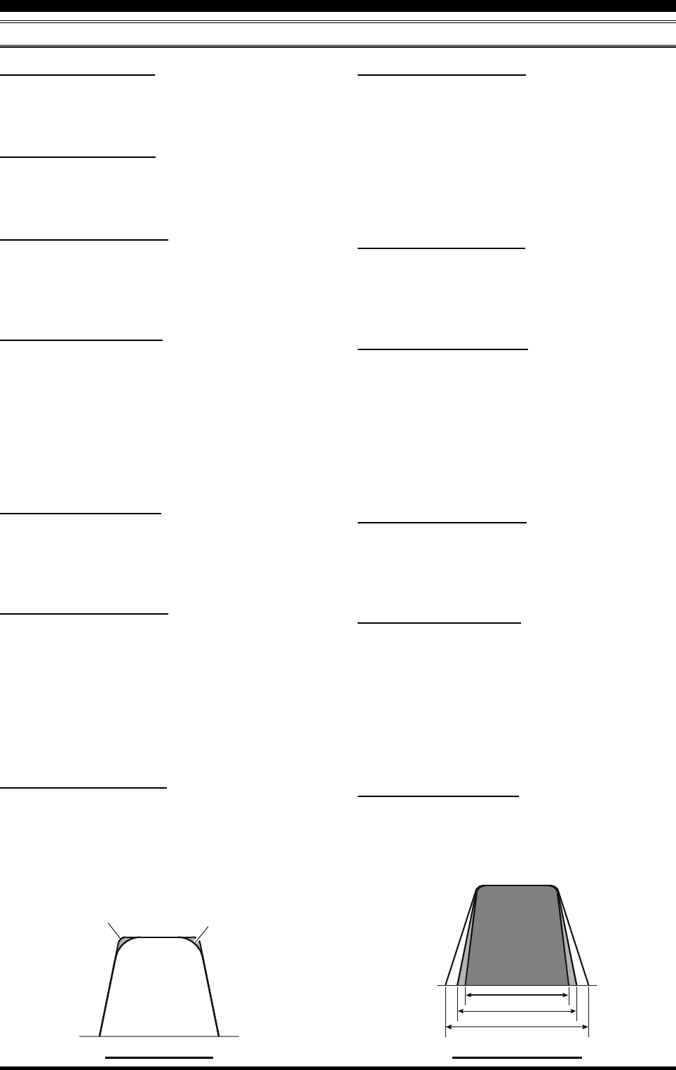
Page 131FTDX5000 OPERATING MANUAL
RX DSP GROUP
119 RDSP HRTY SHP
Function: Selects the passband characteristics of the DSP
filter for the RTTY mode on the HF band.
Available Values: SOFT / SHARP
Default Setting: SHARP
SOFT: Primary importance is attached to the phase
of the filter factor.
SHARP: Primary importance is attached to the ampli-
tude of the filter factor.
120 RDSP HRTY SLP
Function: Selects the shape factor of the DSP filter for
the RTTY mode on the HF band.
Available Values: STEEP / MEDIUM / GENTLE
Default Setting: MEDIUM
121 RDSP HSSB SHP
Function: Selects the passband characteristics of the DSP
filter for the SSB mode on the HF band.
Available Values: SOFT / SHARP
Default Setting: SHARP
SOFT: Primary importance is attached to the phase
of the filter factor.
SHARP: Primary importance is attached to the ampli-
tude of the filter factor.
122 RDSP HSSB SLP
Function: Selects the shape factor of the DSP filter for
the SSB mode on the HF band.
Available Values: STEEP / MEDIUM / GENTLE
Default Setting: MEDIUM
123 RDSP VCW SHP
Function: Selects the passband characteristics of the DSP
filter for the CW mode on the 50 MHz band.
Available Values: SOFT / SHARP
Default Setting: SHARP
SOFT: Primary importance is attached to the phase
of the filter factor.
SHARP: Primary importance is attached to the ampli-
tude of the filter factor.
124 RDSP VCW SLP
Function: Selects the shape factor of the DSP filter for
the CW mode on the 50 MHz band.
Available Values: STEEP / MEDIUM / GENTLE
Default Setting: MEDIUM
MENU MODE
DSP FILTER PASSBANDDSP FILTER SHAPE
SOFT
SHARP
STEEP
GENTLE
MEDIUM
112 RDSP CNTR LV
Function: Adjusts the gain of the Contour filter.
Available Values: –40 ~ 20 dB
Default Setting: –15 dB
113 RDSP CNTR WI
Function: Adjusts the Q-factor of the Contour filter.
Available Values: 1 ~ 11
Default Setting: 10
114 RDSP NOTCH WI
Function: Selects the bandwidth of the DSP NOTCH fil-
ter
Available Values: NARROW / WIDE
Default Setting: WIDE
115 RDSP HCW SHP
Function: Selects the passband characteristics of the DSP
filter for the CW mode on the HF band.
Available Values: SOFT / SHARP
Default Setting: SHARP
SOFT: Primary importance is attached to the phase
of the filter factor.
SHARP: Primary importance is attached to the ampli-
tude of the filter factor.
116 RDSP HCW SLP
Function: Selects the shape factor of the DSP filter for
the CW mode on the HF band.
Available Values: STEEP / MEDIUM / GENTLE
Default Setting: MEDIUM
117 RDSP HPKT SHP
Function: Selects the passband characteristics of the DSP
filter for the PKT mode on the HF band.
Available Values: SOFT / SHARP
Default Setting: SHARP
SOFT: Primary importance is attached to the phase
of the filter factor.
SHARP: Primary importance is attached to the ampli-
tude of the filter factor.
118 RDSP HPKT SLP
Function: Selects the shape factor of the DSP filter for
the PKT mode on the HF band.
Available Values: STEEP / MEDIUM / GENTLE
Default Setting: MEDIUM

Page 132 FTDX5000 OPERATING MANUAL
MENU MODE
SCOPE GROUP
ADVICE:
This group’s adjustment has no effect, if the optional DMU-
2000 Data Management Unit is not connected.
131 SCP 1.8 FIX
Function: Selects the scan start frequency of the FIX mode
Spectrum Scope while monitoring on the 160 m amateur
band.
Available Values: 1800kHz ~ 1999kHz (1 kHz/step)
Default Setting: 1800kHz
132 SCP 3.5 FIX
Function: Selects the scan start frequency of the FIX mode
Spectrum Scope while monitoring on the 80 m amateur
band.
Available Values: 3500kHz ~ 3999kHz (1 kHz/step)
Default Setting: 3500kHz
133 SCP 5.0 FIX
Function: Selects the scan start frequency of the FIX mode
Spectrum Scope while monitoring on the 60 m amateur
band.
Available Values: 5250kHz ~ 5499kHz (1 kHz/step)
Default Setting: 5250kHz
134 SCP 7.0 FIX
Function: Selects the scan start frequency of the FIX mode
Spectrum Scope while monitoring on the 40 m amateur
band.
Available Values: 7000kHz ~ 7299kHz (1 kHz/step)
Default Setting: 7000kHz
135 SCP 10.1 FIX
Function: Selects the scan start frequency of the FIX mode
Spectrum Scope while monitoring on the 30 m amateur
band.
Available Values: 10100kHz ~ 10149 kHz (1 kHz steps)
Default Setting: 10100kHz
125 RDSP VPKT SHP
Function: Selects the passband characteristics of the DSP
filter for the PKT mode on the 50 MHz band.
Available Values: SOFT / SHARP
Default Setting: SHARP
SOFT: Primary importance is attached to the phase
of the filter factor.
SHARP: Primary importance is attached to the ampli-
tude of the filter factor.
126 RDSP VPKT SLP
Function: Selects the shape factor of the DSP filter for
the PKT mode on the 50 MHz band.
Available Values: STEEP / MEDIUM / GENTLE
Default Setting: MEDIUM
127 RDSP VRTY SHP
Function: Selects the passband characteristics of the DSP
filter for the RTTY mode on the 50 MHz band.
Available Values: SOFT / SHARP
Default Setting: SHARP
SOFT: Primary importance is attached to the phase
of the filter factor.
SHARP: Primary importance is attached to the ampli-
tude of the filter factor.
128 RDSP VRTY SLP
Function: Selects the shape factor of the DSP filter for
the RTTY mode on the 50 MHz band.
Available Values: STEEP / MEDIUM / GENTLE
Default Setting: MEDIUM
129 RDSP VSSB SHP
Function: Selects the passband characteristics of the DSP
filter for the SSB mode on the 50 MHz band.
Available Values: SOFT / SHARP
Default Setting: SHARP
SOFT: Primary importance is attached to the phase
of the filter factor.
SHARP: Primary importance is attached to the ampli-
tude of the filter factor.
130 RDSP VSSB SLP
Function: Selects the shape factor of the DSP filter for
the SSB mode on the 50 MHz band.
Available Values: STEEP / MEDIUM / GENTLE
Default Setting: MEDIUM
RX DSP GROUP

Page 133FTDX5000 OPERATING MANUAL
MENU MODE
136 SCP 14.0 FIX
Function: Selects the scan start frequency of the FIX mode
Spectrum Scope while monitoring on the 20 m amateur
band.
Available Values: 14000kHz ~ 14349kHz (1 kHz/step)
Default Setting: 14000kHz
137 SCP 18.0 FIX
Function: Selects the scan start frequency of the FIX mode
Spectrum Scope while monitoring on the 17 m amateur
band.
Available Values: 18000kHz ~ 18199kHz (1 kHz/step)
Default Setting: 18068kHz
138 SCP 21.0 FIX
Function: Selects the scan start frequency of the FIX mode
Spectrum Scope while monitoring on the 15 m amateur
band.
Available Values: 21000kHz ~ 21449kHz (1 kHz/step)
Default Setting: 21000kHz
139 SCP 24.8 FIX
Function: Selects the scan start frequency of the FIX mode
Spectrum Scope while monitoring on the 12 m amateur
band.
Available Values: 24800kHz ~ 24989kHz (1 kHz/step)
Default Setting: 24890kHz
140 SCP 28.0 FIX
Function: Selects the scan start frequency of the FIX mode
Spectrum Scope while monitoring on the 10 m amateur
band.
Available Values: 28000kHz ~ 29699kHz (1 kHz/step)
Default Setting: 28000kHz
141 SCP 50.0 FIX
Function: Selects the scan start frequency of the FIX mode
Spectrum Scope while monitoring on the 6 m amateur band.
Available Values: 50000kHz ~ 53999kHz (1 kHz/step)
Default Setting: 50000kHz
TUNING GROUP
142 TUN DIAL STP
Function: Setting of the Tuning Dial knob’s tuning speed
except the FM and FM-PKT modes.
Available Values: 1Hz / 5Hz / 10Hz
Default Setting: 10Hz
143 TUN CW FINE
Function: Enabling/disabling of the “Fine” tuning speed
in the CW, RTTY, and PKT-SSB modes.
Available Values: DISABLE / ENABLE
Default Setting: DISABLE
ENABLE: Tuning in 1 Hz steps on the CW, RTTY,
and PKT-SSB modes.
DISABLE: Tuning according to the steps determined
via menu item “142 TUN DIAL STP”.
144 TUN MHz SEL
Function: Selects the tuning steps of the [(DOWN)] /
[(UP)] key.
Available Values: 1MHz / 100kHz
Default Setting: 100kHz
145 TUN AM STEP
Function: Selects the tuning steps for the microphone’s
[UP]/[DWN] keys in the AM mode.
Available Values: 2.5kHz / 5kHz / 9kHz / 10kHz / 12.5 kHz
Default Setting: 5kHz
146 TUN FM STEP
Function: Selects the tuning steps for the microphone’s
[UP]/[DWN] keys in the FM and FM-PKT modes.
Available Values: 5kHz / 6.25kHz / 10kHz / 12.5kHz /
20kHz / 25kHz
Default Setting: 5kHz
147 TUN AM D.LCK
Function: Select whether the Main Tuning Dial knob and
[CLAR(VFO-B)] knob shall be “Enabled” or “Disabled”
on the AM mode.
Available Values: DISABLE / ENABLE
Default Setting: DISABLE
148 TUN FM D.LCK
Function: Select whether the Main Tuning Dial knob and
[CLAR(VFO-B)] knob shall be “Enabled” or “Disabled”
on the FM mode.
Available Values: DISABLE / ENABLE
Default Setting: DISABLE
149 TUN FM DIAL
Function: Setting of the Tuning Dial knob’s tuning speed
in the FM mode.
Available Values: 10Hz / 100Hz
Default Setting: 100Hz
SCOPE GROUP

Page 134 FTDX5000 OPERATING MANUAL
MENU MODE
TX AUDIO GROUP
151 TAUD EQ1 FRQ
Function: Selects the center frequency of the lower range
for the parametric microphone equalizer.
Available Values: OFF / 100Hz ~ 700Hz (100 Hz/step)
Default Setting: OFF
OFF: The equalizer gain and Q-factor are
set to factory defaults (flat).
100Hz ~ 700Hz: Center frequencies of 100 Hz ~ 700
Hz. You may adjust the equalizer
gain and Q-factor at this selected
audio frequency via menu items
“152 TAUD EQ1 LVL” and “153
TAUD EQ1 BW”.
152 TAUD EQ1 LVL
Function: Adjusts the equalizer gain of the low range of
the parametric microphone equalizer.
Available Values: –20 ~ 10
Default Setting: 5
153 TAUD EQ1 BW
Function: Adjusts the Q-factor of the low range of the
parametric microphone equalizer.
Available Values: 1 ~ 10
Default Setting: 10
154 TAUD EQ2 FRQ
Function: Selects the center frequency of the middle
range for the parametric microphone equalizer.
Available Values: OFF / 700Hz ~ 1500Hz (100 Hz/step)
Default Setting: OFF
OFF: The equalizer gain and Q-factor are
set to factory defaults (flat).
700Hz ~ 1500Hz: Center frequencies of 700 Hz ~
1500 Hz. You may adjust the equal-
izer gain and Q-factor at this se-
lected audio frequency via menu
items “155 TAUD EQ2 LVL” and
“156 TAUD EQ2 BW”.
155 TAUD EQ2 LVL
Function: Adjusts the equalizer gain of the middle range
of the parametric microphone equalizer.
Available Values: –20 ~ 10
Default Setting: 5
156 TAUD EQ2 BW
Function: Adjusts the Q-factor of the middle range of
the parametric microphone equalizer.
Available Values: 1 ~ 10
Default Setting: 10
150 TUN MY BAND
Function: Programs a band to be skipped while selecting
bands using the [CLAR(VFO-B)] knob.
Available Values: 1.8M ~ 50M / GEN / T14M / T28M /
T50M
Default Setting: 1.8M ~ 50M / GEN: ON,
T14M / T28M / T50M: OFF
To program the band to be skipped, rotate the (VFO-
B)[SELECT] knob to recall the band to be skipped while
selecting bands via the [CLAR(VFO-B)] knob, then press
the [ENT] key (one of the [BAND] buttons) to change this
setting to “OFF”. Repeat the same procedures to cancel the
setting (change the “OFF” notation to “ON”).
TUNING GROUP

Page 135FTDX5000 OPERATING MANUAL
TX AUDIO GROUP
157 TAUD EQ3 FRQ
Function: Selects the center frequency of the high range
for the parametric microphone equalizer.
Available Values: OFF / 1500Hz ~ 3200Hz (100 Hz/step)
Default Setting: OFF
OFF: The equalizer gain and Q-factor
are set to factory defaults (flat).
1500Hz ~ 3200Hz: Center frequencies of 1500 Hz ~
3200 Hz. You may adjust the
equalizer gain and Q-factor in this
selected audio frequency via menu
items “158 TAUD EQ3 LVL” and
“159 TAUD EQ3 BW”.
158 TAUD EQ3 LVL
Function: Adjusts the equalizer gain of the high range of
the parametric microphone equalizer.
Available Values: –20 ~ 10
Default Setting: 5
159 TAUD EQ3 BW
Function: Adjusts the Q-factor of the high range of the
parametric microphone equalizer.
Available Values: 1 ~ 10
Default Setting: 10
160 TAUD PE1 FRQ
Function: Selects the center frequency of the lower range
for the parametric microphone equalizer when the speech
processor is activated.
Available Values: OFF / 100Hz ~ 700Hz (100 Hz/step)
Default Setting: 200Hz
OFF: The equalizer gain and Q-factor are
set to factory defaults (flat).
100Hz ~ 700Hz: Center frequencies of 100 Hz ~ 700
Hz. You may adjust the equalizer
gain and Q-factor at this selected
audio frequency via menu items “161
TAUD PE1 LVL” and “162 TAUD
PE1 BW”.
161 TAUD PE1 LVL
Function: Adjusts the equalizer gain of the low range of
the parametric microphone equalizer when the speech pro-
cessor is activated.
Available Values: –20 ~ 10
Default Setting: 0
162 TAUD PE1 BW
Function: Adjusts the Q-factor of the low range of the
parametric microphone equalizer when the speech proces-
sor is activated.
Available Values: 1 ~ 10
Default Setting: 2
163 TAUD PE2 FRQ
Function: Selects the center frequency of the middle range
for the parametric microphone equalizer when the speech
processor is activated.
Available Values: OFF / 700Hz ~ 1500Hz (100 Hz/step)
Default Setting: 800Hz
OFF: The equalizer gain and Q-factor are
set to factory defaults (flat).
700Hz ~ 1500Hz: Center frequencies of 700 Hz ~
1500 Hz. You may adjust the equal-
izer gain and Q-factor at this se-
lected audio frequency via menu
items “164 TAUD PE2 LVL” and
“165 TAUD PE2 BW”.
164 TAUD PE2 LVL
Function: Adjusts the equalizer gain of the middle range
of the parametric microphone equalizer when the speech
processor is activated.
Available Values: –20 ~ 10
Default Setting: 0
165 TAUD PE2 BW
Function: Adjusts the Q-factor of the middle range of the
parametric microphone equalizer when the speech proces-
sor is activated.
Available Values: 1 ~ 10
Default Setting: 1
166 TAUD PE3 FRQ
Function: Selects the center frequency of the high range
for the parametric microphone equalizer when the speech
processor is activated.
Available Values: OFF / 1500Hz ~ 3200Hz (100 Hz/step)
Default Setting: 2100Hz
OFF: The equalizer gain and Q-factor
are set to factory defaults (flat).
1500Hz ~ 3200Hz: Center frequencies of 1500 Hz ~
3200 Hz. You may adjust the
equalizer gain and Q-factor in this
selected audio frequency via menu
items “167 TAUD PE3 LVL” and
“168 TAUD PE3 BW”.
167 TAUD PE3 LVL
Function: Adjusts the equalizer gain of the high range of
the parametric microphone equalizer when the speech pro-
cessor is activated.
Available Values: –20 ~ 10
Default Setting: 0
168 TAUD PE3 BW
Function: Adjusts the Q-factor of the high range of the
parametric microphone equalizer when the speech proces-
sor is activated.
Available Values: 1 ~ 10
Default Setting: 1
MENU MODE

Page 136 FTDX5000 OPERATING MANUAL
TX GNRL GROUP
169 TGEN BIAS
Function: Adjusts the Bias level of the Final Amplifier
while in “Class-A” operation.
Available Values: 1 ~ 100
Default Setting: 100
170 TGEN MAX PWR
Function: Selects a maximum output power limit.
Available Values: 20W / 50W / 100W / 200W
Default Setting: 200W
171 TGEN PWR CTRL
Function: Configures the [RF PWR] knob.
Available Values: ALL MODE / CARRIER
Default Setting: ALL MODE
ALL MODE: The [RF PWR] knob is enabled on all
modes.
CARRIER: The [RF PWR] knob is enabled in all
modes except SSB. In this configuration,
the SSB output power will be set to
maximum, regardless of the [RF PWR]
knob’s position.
172 TGEN ETX-GND
Function: Enables/Disables the TX GND jack on the rear
panel.
Available Values: DISABLE / ENABLE
Default Setting: DISABLE
173 TGEN TUN PWR
Function: Selects a maximum output power limit for driv-
ing the input circuit of an external linear RF amplifier while
tuning (while using the Remote Control function of the
linear RF amplifier).
Available Values: 20W / 50W / 100W / 200W
Default Setting: 100W
174 TGEN VOX SEL
Function: Selects the audio input source for triggering TX
during VOX operation.
Available Values: MIC / DATA
Default Setting: MIC
MIC: The VOX function will be activated by micro-
phone audio input.
DATA: The VOX function will be activated by data
audio input.
175 TGEN ANTI VOX
Function: Adjusts the Anti-VOX Trip Gain, which is the
level of negative AF feedback of receiver audio to the
microphone, to prevent receiver audio from activating the
transmitter (via the microphone) during VOX operation.
Available Values: 1 ~ 100
Default Setting: 100
176 TGEN EMRGNCY
Function: Enables Tx/Rx operation on the Alaska Emer-
gency Channel, 5167.5 kHz.
Available Values: DISABLE / ENABLE
Default Setting: DISABLE
When this Menu Item is set to “ENABLE”, the spot fre-
quency of 5167.5 kHz will be enabled. The Alaska Emer-
gency Channel will be found between the Memory chan-
nels “P-1” and “01 (or 1-01)”.
IMPORTANT:
The use of this frequency is restricted to stations operat-
ing in or near Alaska, and only for emergency purposes
(never for routine operations). See §97.401(c) of the FCC’s
regulations for details.
MENU MODE

Page 137FTDX5000 OPERATING MANUAL
MENU MODE
NOTE

Page 138 FTDX5000 OPERATING MANUAL
SPECIFICATIONS
GENERAL
Rx Frequency Range: 30 kHz - 60 MHz (operating)
1.8 - 29.7 MHz, 50 - 54 MHz (specified performance, Amateur bands only)
Tx Frequency Ranges: 1.8 - 29.7 MHz, 50 - 54 MHz (Amateur bands only)
5.16750MHz, 5.33200MHz, 5.34800MHz,
5.36800MHz, 5.37300MHz, 5.40500MHz (USA version only)
Frequency Stability: ±0.05 ppm (MP version, after 1 minute @+14 °F ~ +140 °F [–10 °C ~ +60 °C])
±0.5 ppm (after 1 minute @+14 °F ~ +140 °F [–10 °C ~ +60 °C])
Operating Temperature Range: +14 °F ~ +140 °F (–10 °C ~ +60 °C)
Emission Modes: A1A (CW), A3E (AM), J3E (LSB, USB), F3E (FM),
F1B (RTTY), F1D (PACKET), F2D (PACKET)
Frequency Steps: 1/5/10 Hz (SSB,CW, & AM), 100 Hz (FM)
Antenna Impedance: 50 Ohms, unbalanced
16.7 - 150 Ohms, unbalanced (Tuner ON, 1.8 - 29.7 MHz Amateur bands)
25 - 100 Ohms, unbalanced (Tuner ON, 50 MHz Amateur band)
Power Consumption: Rx (no signal) 70 VA
(@117 VAC) Rx (signal present) 80 VA
Tx (200 W) 720 VA
Supply Voltage: AC 90 V - AC 264 V
Dimensions (WxHxD): 18.2” x 5.3” x 15.3” (462 x 135 x 389 mm) w/o knob and connector
Weight (approx.): 46.3 lbs (21 kg)
TRANSMITTER
Power Output: 10 - 200 watts (CW, LSB, USB, FM, RTTY, PKT)
5 - 50 watts (AM carrier)
10 - 75 watts (Class A: LSB, USB)
Modulation Types: J3E (SSB): Balanced,
A3E (AM): Low-Level (Early Stage)
F3E (FM): Variable Reactance
Maximum FM Deviation: ±5.0 kHz/±2.5 kHz
Harmonic Radiation: Better than –60 dB (1.8 - 50 MHz Amateur bands)
SSB Carrier Suppression: At least 60 dB below peak output
Undesired Sideband Suppression: At least 60 dB below peak output
Audio Response (SSB): Not more than –6 dB from 300 to 2700 Hz
3rd-order IMD: –31 dB @14 MHz, 100 watts PEP
–40 dB @14 MHz, Class A: 75 watts PEP
Bandwidth: 500 Hz (CW)
3.0 kHz (LSB, USB)
6.0 kHz (AM)
16 kHz (FM)
Microphone Impedance: 600 Ohms (200 to 10 k Ohms)

Page 139FTDX5000 OPERATING MANUAL
RECEIVER
Circuit Type: VFO-A; Double-conversion superheterodyne
VFO-B; Triple-conversion superheterodyne
Intermediate Frequencies: VFO-A; 9 MHz /30 kHz (24 kHz for AM/FM)
VFO-B; 40.455 MHz/455 kHz /30 kHz (24 kHz for AM/FM)
Sensitivity: SSB (2.4 kHz, 10 dB S+N/N)
2 µV (0.5 - 1.8 MHz, IPO1)
0.2 µV (1.8 - 30 MHz, AMP2)
0.125 µV (50 - 54 MHz, AMP2)
AM (6 kHz, 10 dB S+N/N, 30 % modulation @400 Hz)
6 µV (0.5 - 1.8 MHz, IPO1)
2 µV (1.8 - 30 MHz, AMP2)
1 µV (50 - 54 MHz, AMP2)
FM (BW: 15 kHz, 12 dB SINAD)
0.5 µV (28 - 30 MHz, AMP2)
0.35 µV (50 - 54 MHz, AMP2)
There is no specification in frequency ranges not listed.
Squelch Sensitivity (AMP2): SSB/CW/AM
2 µV (0.1 - 30 MHz)
2 µV (50 - 54 MHz)
FM
1 µV (28 - 30 MHz)
1 µV (50 - 54 MHz)
There is no specification in frequency ranges not listed.
Selectivity (–6/–60 dB): Mode –6 dB –60 dB
CW 0.5 kHz or better 750 Hz or less
LSB, USB 2.4 kHz or better 3.6 kHz or less
AM 6 kHz or better 15 kHz or less
FM 12 kHz or better 30 kHz or less
Image Rejection: 70 dB or better (1.8 - 29.7 MHz Amateur bands, VRF: ON)
60 dB or better (50 MHz Amateur band)
Maximum Audio Output: 2.5 W into 4 Ohms with 10% THD
Audio Output Impedance: 4 to 8 Ohms (4 Ohms: nominal)
Conducted Radiation: Less than 4000 µµW
Specifications are subject to change, in the interest of technical improvement, without notice or obligation, and are
guaranteed only within the amateur bands.
SPECIFICATIONS
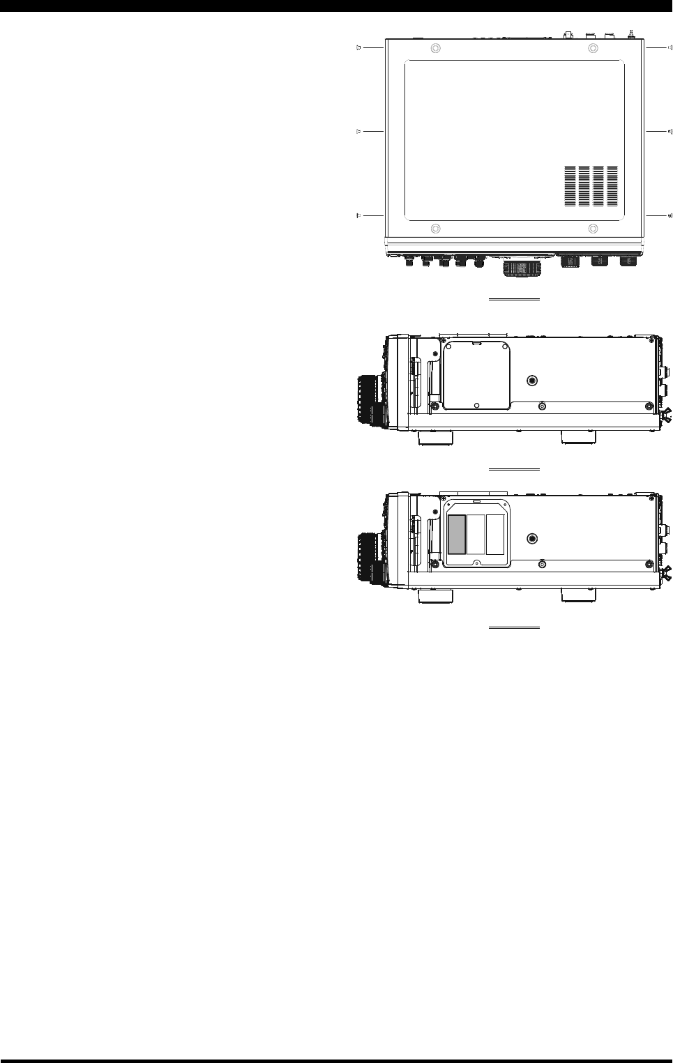
Page 140 FTDX5000 OPERATING MANUAL
I
NSTALLATION
OF
THE
O
PTIONAL
R
OOFING
F
ILTER (XF-126CN)
1. Turn the front panel [POWER] switch “off,” then turn
the rear panel’s [POWER] switch “off.”
2. Disconnect all the cables from the transceiver.
3. Referring to Figure 1, remove the three screws from
each side of the transceiver and four screws from the
top of the transceiver, then remove the top cover.
4. Refer to Figure 2, there is the metal plate on the right
side of the transceiver. A mounting position of the op-
tional filter is inside of this. Remove the three screws
affixing the metal plate, then remove the metal plate.
5. Refer to Figure 3, position the filter so that its connec-
tors are aligned with the mounting pins on the board,
and push it into place.
6. Replace the metal plate and its three screws.
7. Replace the top cover and its ten screws.
8. Filter installation is now complete.
9. Connect the all cables to the transceiver.
FIGURE 1
FIGURE 2
FIGURE 3

Page 141FTDX5000 OPERATING MANUAL
NOTE

Page 142 FTDX5000 OPERATING MANUAL
A
A Switch ....................................................................... 22
A
B Switch ........................................................... 24, 83
A
B Switch ............................................................... 24,
A
M Switch ....................................................... 24, 102
Accessory ....................................................................... 4
AF GAIN Knob ..................................................... 21, 38
AFSK Operation ........................................................ 112
AGC Switch ........................................................... 19, 67
Alaska Emergency Frequency ................................... 106
All Reset ........................................................................ 7
AM Operation .............................................................. 70
APF .................................................................. 27, 29, 92
ATT Switch ............................................................ 18, 52
ATU ............................................................................. 72
Audio Peak Filter ............................................. 27, 29, 92
Audio Playback ............................................................ 45
Automatic Antenna Tuner ............................................ 72
B
B Switch ...................................................................... 22
Band Stack ................................................................... 47
Basic Operation ........................................................... 37
Beacon ......................................................................... 95
BK-IN Switch .................................................. 25, 86, 88
C
Clarifier ........................................................................ 40
Class-A Operation ........................................................ 78
Connector Pinout ......................................................... 15
CONT Switch .................................................. 27, 29, 58
Contest Memory Keyer ................................................ 94
Contest Number ........................................................... 97
CONTOUR .................................................................. 58
Custom Switch ............................................................. 47
CW Delay Time ........................................................... 93
CW Operation .............................................................. 86
CW Pitch ...................................................................... 93
CW Reverse ................................................................. 92
CW Spotting ................................................................ 91
D
Digital Noise Reduction .............................................. 64
Digital Notch Filter ...................................................... 64
DIM Switch ............................................................. 6, 41
DNF Switch ..................................................... 28, 29, 64
DNR Switch ..................................................... 28, 29, 64
Dual Receive ................................................................ 42
E
Electronic Keyer .......................................................... 88
Erasing Memory ........................................................ 103
F
FM Operation .............................................................. 98
Full Break-in .......................................................... 87, 89
Full Reset ....................................................................... 7
I
IF SHIFT ......................................................... 27, 28, 60
Installation ..................................................................... 8
Installation of Option ................................................. 140
Intercept Point Optimization ................................. 18, 51
IPO Switch ............................................................. 18, 51
K
KEYER Switch ...................................................... 25, 88
Keyer Weight Ratio ..................................................... 90
L
LOCK Switch ........................................................ 23, 41
M
M
A Switch ........................................................ 24, 104
Memory Check .......................................................... 103
Memory Group .......................................................... 105
Memory Recall .......................................................... 102
Memory Reset ................................................................ 7
Memory Scan ............................................................. 108
Memory Storage ........................................................ 102
Memory Tune ............................................................ 104
Menu Mode ............................................................... 116
Menu Reset .................................................................... 7
Message Memory......................................................... 94
METER Knob .............................................................. 19
MIC ........................................................................ 20, 70
MONI Knob........................................................... 19, 81
MONI Switch......................................................... 17, 81
Moving Memory ........................................................ 104
MOX Switch ................................................................ 17
Mute ............................................................................. 69
My Band ...................................................................... 46
INDEX

Page 143FTDX5000 OPERATING MANUAL
N
NAR Switch ........................................................... 29, 65
NARROW ................................................................... 65
NB Knob ................................................................ 19, 66
NB Switch .............................................................. 25, 66
Noise Blanker ........................................................ 25, 66
NOTCH Filter .................................................. 28, 29, 63
O
Option ............................................................................ 4
P
P.BACK ....................................................................... 45
Packet Operation ....................................................... 110
Parametric Microphone Equalizer ............................... 74
Plug Pinout .................................................................. 15
PMS ........................................................................... 109
POWER Switch ..................................................... 16, 38
PROC Knob ........................................................... 19, 76
PROC Switch ......................................................... 17, 76
Programmable Memory Scan .................................... 109
Q
QMB .................................................................... 22, 101
Quick Memory Bank ................................................. 101
Quick Split ................................................................... 84
R
RCL Switch .......................................................... 22, 101
Repeater Operation ...................................................... 99
Reset .............................................................................. 7
RF GAIN Knob ..................................................... 21, 53
RF PWR Knob ....................................................... 20, 71
Roofing Filter ........................................................ 18, 56
Rotator Control ............................................................ 48
RTTY Operation ........................................................ 111
RX ANT ................................................................. 17, 39
S
Scan ........................................................................... 107
Semi Break-in .............................................................. 87
SHIFT Switch .................................................. 27, 28, 60
Sloped AGC ................................................................. 68
Specification .............................................................. 138
Speech Processor ......................................................... 76
Split Operation ............................................................. 82
SQL........................................................................ 19, 39
SSB Operation ............................................................. 70
SSB Transmit Bandwidth ............................................ 77
STO Switch .......................................................... 22, 101
SUB DISPLAY ................................................ 25, 26, 28
T
Text Memory ............................................................... 96
TUNE Switch ........................................................ 17, 72
TX Clarifier ................................................................. 82
TXW Switch .......................................................... 23, 83
V
V/M Switch .......................................................... 24, 101
VFO Scan .................................................................. 107
VFO Tracking Feature ................................................. 83
Voice Memory ............................................................. 80
VOX Switch ........................................................... 17, 81
VRF Switch ..................................................... 27, 28, 54
W
WIDTH Switch ................................................ 28, 29, 61
INDEX

Page 144 FTDX5000 OPERATING MANUAL
NOTE

1. Changes or modifications to this device not expressly approved by VERTEX STANDARD could
void the user’s authorization to operate this device.
2. This device complies with part 15 of the FCC Rules. Operation is subject to the following two
conditions; (1) this device may not cause harmful interference, and (2) this device must accept any
interference including interference that may cause undesired operation.
3. The scanning receiver in this equipment is incapable of tuning, or readily being altered, by the
User to operate within the frequency bands allocated to the Domestic public Cellular
Telecommunications Service in Part 22.
DECLARATION BY MANUFACTURER
The scanner receiver is not a digital scanner and is incapable of being converted or modified a digital
scanner receiver by any user.
WARNING: MODIFICATION OF THIS DEVICE TO RECEIVE CELLULAR RADIOTELEPHONE SERVICE
SIGNALS IS PROHIBITED UNDER FCC RULES AND FEDERAL LAW.
This equipment has been tested and found to comply with the limits for a Class B digital device,
pursuant to Part 15 of the FCC Rules. These limits are designed to provide reasonable protection
against harmful interference in a residential installation. This equipment generates, uses and can
radiate radio frequency energy and, if not installed and used in accordance with the instructions, may
cause harmful interference to radio communications. However, there is no guarantee that interference
will not occur in a particular installation.
If this equipment does cause harmful interference to radio or television reception, which can be
determined by turning the equipment off and on, the user is encouraged to try to correct the interference
by one or more of the following measures:
-- Reorient or relocate the receiving antenna.
-- Increase the separation between the equipment and receiver.
-- Connect the equipment into an outlet on a circuit different from that to which the receiver is
connected.
-- Consult the dealer or an experienced radio/TV technician for help.

Copyright 2010
VERTEX STANDARD CO., LTD.
All rights reserved
No portion of this manual
may be reproduced without
the permission of
VERTEX STANDARD CO., LTD.
Printed in Japan
1001X-0Y
EH036H100