Yaesu Musen 20361X61 HF Transceiver with Scanning Receiver User Manual P65
Yaesu Musen Co., Ltd. HF Transceiver with Scanning Receiver P65
Contents
- 1. Users Manual 1
- 2. Users Manual 2
Users Manual 1
HF/50 MH
Z
T
RANSCEIVER
FTDX5000 S
ERIES
O
PERATING
M
ANUAL
VERTEX STANDARD CO., LTD.
4-8-8 Nakameguro, Meguro-Ku, Tokyo 153-8644, Japan
VERTEX STANDARD
US Headquarters
10900 Walker Street, Cypress, CA 90630, U.S.A.
YAESU UK LTD.
Unit 12, Sun Valley Business Park, Winnall Close
Winchester, Hampshire, SO23 0LB, U.K.
VERTEX STANDARD HK LTD.
Unit 5, 20/F., Seaview Centre, 139-141 Hoi Bun Road,
Kwun Tong, Kowloon, Hong Kong
VERTEX STANDARD (AUSTRALIA) PTY., LTD.
Normanby Business Park, Unit 14/45 Normanby Road
Notting Hill 3168, Victoria, Australia

ABOUT THIS MANUAL . . .
The FTDX5000 is a leading-edge transceiver with a number of new and exciting features, some of which may be unfamiliar
to you. In order to gain the most enjoyment and operating efficiency from your FTDX5000, we recommend that you read
this manual in its entirety, and keep it handy for reference as you explore the many capabilities of your new transceiver.
Before using your FTDX5000, be sure to read and follow the instructions in the “Before You Begin” section of this manual.

Page 1FTDX5000 OPERATING MANUAL
GENERAL DESCRIPTION
Congratulations on your purchase of the FTDX5000 Yaesu
amateur transceiver!
Whether this is your first rig, or Yaesu equipment is already
the backbone of your station, rest assured this transceiver
will provide many hours of operating pleasure for years to
come.
The FTDX5000 is an elite-class HF transceiver and will pro-
vide exceptional transmit and receive performance. The
FTDX5000 is designed for the most competitive operating
situations, whether you operate in contests, DX, or digital-
mode environments.
Built on the foundation of the popular FTDX9000 transceiver,
and carrying on the proud tradition of the FT-1000 series,
the FTDX5000 provides up to 200 Watts of power output on
SSB, CW, and FM (50 Watts AM carrier). Digital Signal Pro-
cessing (DSP) is utilized throughout the design, providing
leading edge performance on both transmit and receive.
Available as an option, the DMU-2000 Data Management
Unit will provide extensive display capabilities via a user-
supplied computer monitor: Band Scope, Audio Scope, X-Y
Oscilloscope, World Clock, Rotator Control, extensive trans-
ceiver status displays, and station logging capability.
The Yaesu-exclusive VRF (Variable RF Front-End Filter)
provides exceptional protection from strong nearby signals,
and serves as a high-performance Preselector, ideal for multi-
operator contest environments. The filter is manually tuned,
allowing the operator to optimize sensitivity or signal rejec-
tion with the turn of a knob. For the ultimate in receiver RF
selectivity, the optional RF µ-Tuning Kits may be connected
via the rear panel, providing extraordinarily sharp selectivity
and receiver protection from close-in interference on a
crowded band.
Superb receiver performance is a direct legacy from the leg-
endary FTDX9000, FT-1000D, and FT-1000MP transceiv-
ers. In the VFO-A receive front end, you may select one of
two RF preamplifiers, or one of two IPO (Intercept Point
Optimization) settings, and/or three levels of RF attenuation
in 6-dB steps. The IPO settings provide direct feed to the
first mixer (VFO-B has one IPO setting), Dual Receives are
built into every FTDX5000. Both VFO-A and VFO-B receiv-
ers utilizes DSP filtering, and incorporate many of the fea-
tures of the FTDX9000, such as Variable Bandwidth, IF Shift,
and Passband Contour tuning. Digital Noise Reduction and
Digital Auto-Notch Filtering are also provided, along with a
manually-tuned IF Notch filter. The Sub receiver, used for
monitoring within the same band as the Main receiver, is
ideal for watching both sides of a pile-up, or keeping an ear
on a DX station that is working stations by call area, etc.
On the transmit side, the Yaesu-exclusive Three-Band Para-
metric Microphone Equalizer allows precise and flexible
adjustment of the wave-form to complement your voice. The
microphone Amplitude, Center Frequency, and Bandwidth
may be adjusted independently for the low-frequency, mid-
range, and high-audio-frequency spectra. The transmitted
bandwidth may be adjusted, as well.
Advanced features include: Direct Keyboard Entry of fre-
quency and Band Change, Speech Processor, IF Monitor for
Voice modes, CW Pitch control, CW Spot switch, Full CW
QSK, adjustable IF Noise Blanker, and all-mode Squelch.
Four TX/ RX antenna ports, plus a receive-only antenna port,
are provided on the rear panel. The front and rear key jacks
may be configured independently, for paddle input, connec-
tion to a straight key, or computer-driven keying interface.
Both Digital Voice Recording and CW Message Memory are
provided.
Three unique windows on the right side of the front panel,
display the VFO-B frequency and graphically show the VFO-
A and VFO-B DSP settings. In Menu Mode operation, these
windows display the menu values, for easy setting.
Set up of frequency, band and mode is especially convenient
on the FTDX5000. Besides direct frequency entry for both
the Main and Sub VFOs, separate keys are provided for band
selection. Each band key accesses three independent VFO
frequency/mode/filter settings per band. You can establish
separate VFO settings for three different parts of each band.
The two (Main and Sub) VFOs allow simultaneous recep-
tion and display of two different frequencies, even in differ-
ent modes and with different IF bandwidths. The Dual Re-
ceiver audio can be combined, or partially mixed in each head-
phone, or monitored separately in each ear.
In addition, 99 memories are provided to store: frequency, IF
filter selection, clarifier offset, and scan-skip status. What’s
more, five quick-recall (“QMB”) memories can instantly store
operational settings at the push of a button.
The built-in automatic antenna tuner includes 100 memories
of its own, to automatically store antenna matching settings
for quick recall later.
Dedicated AFSK and FSK connection jacks on the rear panel
provide simple Interfacing for digital modes. Optimization
of the Passband filters, DSP settings, carrier insertion point,
and display offset are all possible via the Menu program-
ming system.
The Yaesu CAT system provides a direct link to the trans-
ceiver CPU for computer control and customization of tun-
ing, scanning, and other operating functions. The FTDX5000
includes a built-in data level converter for direct connection
to a personal computer serial port. Yaesu products are sup-
ported by most of the leading contest and DX logging pro-
grams. The extensive programming protocol is described in
the CAT System, if you wish to write your own software!
Advanced technology is only part of the FTDX5000 story.
Vertex Standard stands behind our products with a world-
wide network of dealers and service centers. We greatly ap-
preciate your investment in the FTDX5000, and we look for-
ward to helping you get the most enjoyment from your new
transceiver.
Please feel free to contact your nearest dealer, or one of Ver-
tex Standard's national headquarters offices, for technical
advice, interfacing assistance, or accessory recommendation.
Watch the Vertex Standard U.S.A. Home Page for late break-
ing information about Vertex, Standard Horizon, and Yaesu
products: http://www.vertexstandard.com.
Please read this manual thoroughly, to gain maximum under-
standing of the full capability of the FTDX5000. We thank
you again for your purchase!

Page 2 FTDX5000 OPERATING MANUAL
TABLE OF CONTENTS
General Description ..................................................... 1
Accessories & Options ................................................. 4
Supplied Accessories ............................................... 4
Available Options ..................................................... 4
Before You Begin ......................................................... 6
Connecting AC Power .............................................. 6
Extending the Front Feet .......................................... 6
Adjusting the Main Tuning Dial Torque .................. 6
Resetting the Microprocessor .................................. 7
Resetting Memories (Only) ................................ 7
Menu Resetting ................................................... 7
Full Reset ............................................................ 7
Installation and Interconnections ............................... 8
Antenna Considerations ........................................... 8
About Coaxial Cable ................................................ 8
Grounding ................................................................ 9
Connection of Antenna and Power Cables ............. 10
Connection of Microphone and Headphone .......... 11
Key, Keyer, and Computer-Driven Keying
Interconnections ..................................................... 12
VL-1000 Linear Amplifier Interconnections .......... 13
Interfacing to Other Linear Amplifiers ................... 14
Plug/Connector Pinout Diagrams ............................ 15
Front Panel Controls & Switches ............................. 16
Display Indications .................................................... 30
Rear Panel .................................................................. 33
FH-2 Switches ............................................................ 36
Basic Operation: Receiving on Amateur Bands ...... 37
CLAR (Clarifier) Operation on Main (VFO-A) ..... 40
LOCK ..................................................................... 41
DIM ........................................................................ 41
Operation on 60-Meter (5 MHz) Band
(U.S. version only) ................................................. 41
Convenience Features................................................ 42
Dual Receive .......................................................... 42
Using Headphones for Dual Receive ............... 43
Sideband Diversity Reception .......................... 43
Bandwidth Diversity Reception ....................... 44
P.BACK (Audio Playback) from
Main (VFO-A) Receiver ........................................ 45
“MY Bands” Operation .......................................... 46
Band Stack Operation ............................................ 47
C.S (Custom Switch) .............................................. 47
Rotator Control Functions ...................................... 48
More Frequency Navigation Techniques ............... 49
Keyboard Frequency Entry .............................. 49
Using the [(UP)]/[(DOWN)] Buttons ....... 49
Using the UP/DOWN switches of
the supplied MH-31B8 Hand Microphone ........ 49
Receiver Operation (Front End Block Diagram) ... 50
IPO (Intercept Point Optimization) ........................ 51
ATT ........................................................................ 52
RF Gain (SSB/CW/AM Modes) ............................ 53
Advanced Interference-Suppression Features:
RF Front End ............................................................. 54
Using the VRF (Variable RF Front-end Filter) ...... 54
Interference Rejection
(Signals Off Frequency by Just a Few kHz) ............ 56
R.FLT (Roofing Filters) ......................................... 56
Interference Rejection (Signals within 3 kHz) ........ 58
CONTOUR Control Operation .............................. 58
IF SHIFT Operation ............................................... 60
WIDTH (IF DSP Bandwidth) Tuning .................... 61
Using IF Shift and Width Together ........................ 62
IF Notch Filter Operation ....................................... 63
Digital Noise Reduction (DNR) Operation ............ 64
Digital Notch Filter (DNF) Operation ................... 64
NARROW (NAR) One-Touch IF Filter Selection . 65
IF Noise Blanker (NB) Operation .......................... 66
Tools for Comfortable and Effective Reception ...... 67
AGC (Automatic Gain Control) ............................. 67
SLOPED AGC Operation ................................. 68
Mute Feature (VFO-A Band) ................................. 69
Adjustable Receiver Audio Filter ........................... 69
SSB/AM Mode Transmission .................................... 70
Using the Automatic Antenna Tuner ........................ 72
ATU Operation ....................................................... 72
About ATU Operation ............................................ 73
Enhancing Transmit Signal Quality ......................... 74
Parametric Microphone Equalizer ......................... 74
Using the Speech Processor ................................... 76
Adjusting the SSB Transmitted Bandwidth ........... 77
Low- Distortion CLASS-A Operation .................... 78
Transmitter Convenience Features .......................... 80
Voice Memory ........................................................ 80
VOX (Automatic TX/RX Switching using Voice Control) ............. 81
MONITOR ............................................................. 81
Split Operation Using the TX Clarifier .................. 82
Split-Frequency Operation ..................................... 83
VFO Tracking Feature ...................................... 83
Quick Split Operation ....................................... 84

Page 3FTDX5000 OPERATING MANUAL
TABLE OF CONTENTS
CW Mode Operation ................................................. 86
Setup for Straight Key
(and Straight Key emulation) Operation ................ 86
Using the Built-in Electronic Keyer ....................... 88
Full Break-in (QSK) Operation ........................ 89
Setting the Keyer Weight
(Dot/Space:Dash) Ratio .................................... 90
Selecting the Keyer Operating Mode ............... 90
CW Convenience Features ........................................ 91
CW Spotting (Zero-Beating) .................................. 91
Using CW Reverse ................................................. 92
Audio Peak Filter ................................................... 92
CW Delay Time Setting ......................................... 93
CW Pitch Adjustment ............................................. 93
Contest Memory Keyer .......................................... 94
Message Memory ............................................. 94
Transmitting in the Beacon Mode .............. 95
TEXT Memory ................................................. 96
Contest Number Programming ................... 97
Decrementing the Contest Number ............. 97
FM Mode Operation ................................................. 98
Basic Operation ...................................................... 98
Repeater Operation ................................................ 99
Memory Operation .................................................. 100
Convenient Memory functions ............................. 100
QMB (Quick Memory Bank) ............................... 101
Regular Memory Operation ................................. 102
Memory Storage ............................................. 102
Memory Channel Recall ................................. 102
Checking a Memory Channel’s Status ............ 103
Erasing Memory Channel Data ...................... 103
Moving Memory Data to the VFO-A ............. 104
Memory Tune Operation ................................ 104
Memory Groups ................................................... 105
Memory Group Assignment ........................... 105
Choosing the Desired Memory Group ........... 105
Operation on Alaska Emergency Frequency:
5167.5 kHz (U.S. Version Only) .............................. 106
VFO and Memory Scanning ................................... 107
VFO Scanning ...................................................... 107
Memory Scan ....................................................... 108
PMS ........................................................................... 109
Packet Operation ..................................................... 110
Packet Setup (Including Subcarrier Frequency) .. 110
Basic Setup .......................................................... 110
RTTY (Radio Teletype) Operation ......................... 111
Setting Up for RTTY Operation........................... 111
Basic Setup .......................................................... 111
Miscellaneous AFSK-Based Data Modes .............. 112
About the Transverter Output Terminal ............... 114
Setup .................................................................... 114
Operation ............................................................. 115
Menu Mode .............................................................. 116
Using the Menu .................................................... 116
Menu Mode Reset ................................................ 116
AGC Group .......................................................... 121
DISPLAY Group .................................................. 121
DVS Group .......................................................... 122
KEYER Group ..................................................... 123
GENERAL Group ................................................ 124
MODE-AM Group ............................................... 125
MODE-CW Group ............................................... 126
MODE-DAT Group ............................................. 127
MODE-FM Group ............................................... 128
MODE-RTY Group .............................................. 128
MODE-SSB Group .............................................. 129
RX AUDIO Group ............................................... 130
RX GNRL Group ................................................. 130
RX DSP Group .................................................... 131
SCOPE Group ...................................................... 132
TUNING Group ................................................... 133
TX AUDIO Group ............................................... 134
TX GNRL Group ................................................. 136
Specifications ............................................................ 138
Installation of the Optional Roofing Filter ............ 140
Index ......................................................................... 142

Page 4 FTDX5000 OPERATING MANUAL
ACCESSORIES & OPTIONS
SUPPLIED ACCESSORIES
Hand Microphone (MH-31B8)1 pc A07890001
Remote Control Keypad (FH-2)1 pc A07890001
AC Power Cord 1 pc T9017882: USA
T9013285: Europe
T9013283A: Australia
4-pin DIN Plug 1 pc P0091004
5-pin DIN Plug 1 pc P0091006
1/4-inch 3-contact Plug 1 pcs P0091513
3.5 mm 3-contact Plug 1 pcs P0091046
3.5 mm 2-contact Plug 1 pcs P0090034
RCA Plug 2 pcs P0091365
Operating Manual 1 pc
Warranty Card 1 pc
SM-5000 Station Monitor 1 pc (FTDX5000MP and FTDX5000D version only)
AVAILABLE OPTIONS
MD-200A8X Ultra-High-Fidelity Desk-Top Microphone
YH-77STA Lightweight Stereo Headphone
SM-5000 Station Monitor (It is attached with FTDX5000MP and FTDX5000D)
SP-2000 External Speaker with Audio Filter
VL-1000/VP-1000 Linear Amplifier/AC Power Supply
DMU-2000 Data Management Unit
RF µTuning Kit A For 160 m Band
RF µTuning Kit B For 80/40 m Bands
RF µTuning Kit C For 30/20 m Bands
FH-2 Remote Control Keypad
YF-126CN CW Narrow Filter (C/F: 9 MHz, B/W: 300 Hz) (It is installed with FTDX5000MP)
T9101556 Antenna Rotator Connection Cable

Page 5FTDX5000 OPERATING MANUAL
NOTE
Page 6 FTDX5000 OPERATING MANUAL
CONNECTING AC POWER
The FTDX5000 is equipped with a universal power sup-
ply supporting 100 V to 264 V AC.
Therefore, the FTDX5000 will operate on a voltage range
from 100V to 264 V without changing a voltage select
switch. Just use the power plug that matches your wall
outlet.
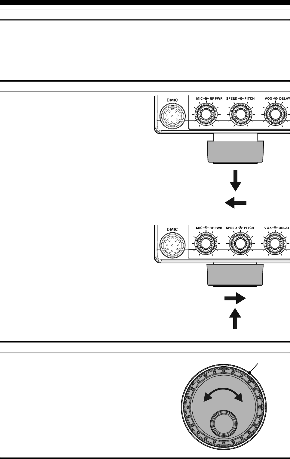
ADJUSTING THE MAIN TUNING DIAL TORQUE
The torque (drag) of the Main Tuning Dial knob may be
adjusted according to your preferences. Simply hold down
the rear skirt of the knob, and while holding it in place
rotate the knob itself to the right to reduce the drag or to
the left to increase the drag.
EXTENDING THE FRONT FEET
BEFORE YOU BEGIN
In order to elevate the front panel for easy viewing, the
front left and right feet of the bottom case may be extended.
Pull the front legs outward from the bottom panel.
Rotate the legs counter-clockwise to lock them in the
extended position. Be sure the legs have locked se-
curely in place, because the transceiver is quite heavy
and an unlocked leg could result in damage, should
the transceiver move suddenly.
Retracting the Front Feet
Rotate the legs clockwise, and push them inward while
rotating to the right.
The front feet should now be locked in the retracted
position.
TIGHTEN LOOSE
Hold the Skirt
Page 7FTDX5000 OPERATING MANUAL
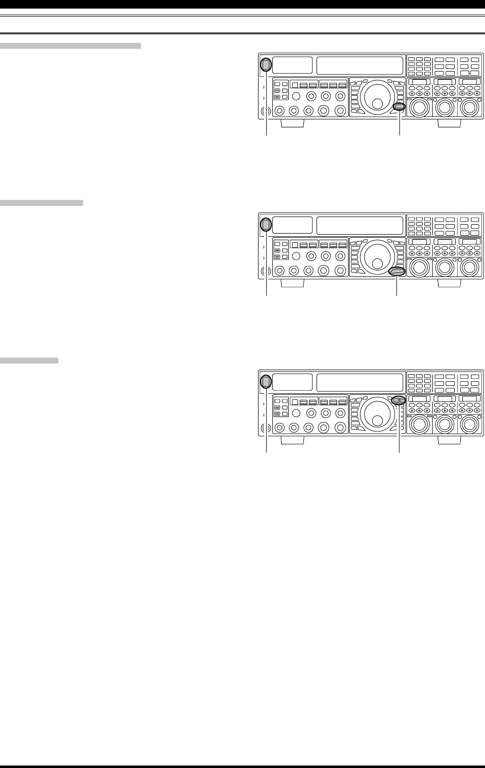
RESETTING THE MICROPROCESSOR
RESETTING MEMORIES (ONLY)
Use this procedure to reset (clear out) the previously stored
Memory channels, without affecting any configuration
changes you may have made to the Menu settings.
1. Press the front panel [POWER] switch to turn the trans-
ceiver off.
2. Press and hold in the [A
M] button; while holding it
in, press and hold in the front panel [POWER] switch
to turn the transceiver on. Once the transceiver comes
on, release the buttons.
MENU RESETTING
Use this procedure to restore the Menu settings to their
factory defaults, without affecting the memories you have
programmed.
1. Press the front panel [POWER] switch to turn the trans-
ceiver off.
2. Press and hold in the [MENU] button; while holding it
in, press and hold in the front panel [POWER] switch
to turn the transceiver on. Once the transceiver comes
on, release the buttons.
FULL RESET
Use this procedure to restore all Menu and Memory set-
tings to their original factory defaults. All Memories will
be cleared out by this procedure.
1. Press the front panel [POWER] switch to turn the trans-
ceiver off.
2. Press and hold in the [FAST] and [LOCK] buttons;
while holding them in, press and hold in the front panel
[POWER] switch to turn the transceiver on. Once the
transceiver comes on, release the switches.
BEFORE YOU BEGIN
[POWER] Switch [A
M] Button
[POWER] Switch [MENU] Button
[POWER] Switch [FAST] / [LOCK] Button
Page 8 FTDX5000 OPERATING MANUAL
ANTENNA CONSIDERATIONS
The FTDX5000 is designed for use with any antenna system providing a 50 Ohm resistive impedance at the desired operat-
ing frequency. While minor excursions from the 50-Ohm specification are of no consequence, if the Standing Wave Ratio
(SWR) present at the Antenna jack is greater than 3:1, the Antenna Tuner may not be able to reduce the impedance mis-
match to an acceptable value.
It is very important, therefore, to ensure that the impedance of the antenna system utilized with the FTDX5000 be as close
as possible to the specified 50-Ohm value.
Note that the “G5RV” type antenna does not provide a 50-Ohm impedance on all HF Amateur bands, and an external wide
range antenna coupler must be used with this antenna type.
Any antenna to be used with the FTDX5000 must, ultimately, be fed with 50 Ohm coaxial cable. Therefore, when using a
“balanced” antenna such as a dipole, remember that a balun or other matching/balancing device must be used to ensure
proper antenna performance.
The same precautions apply to any additional (receive-only) antennas connected to the RX ANT jack; if your receive-only
antennas do not have an impedance near 50 Ohms at the operating frequency, you may need to install an external antenna
tuner to obtain optimum performance.
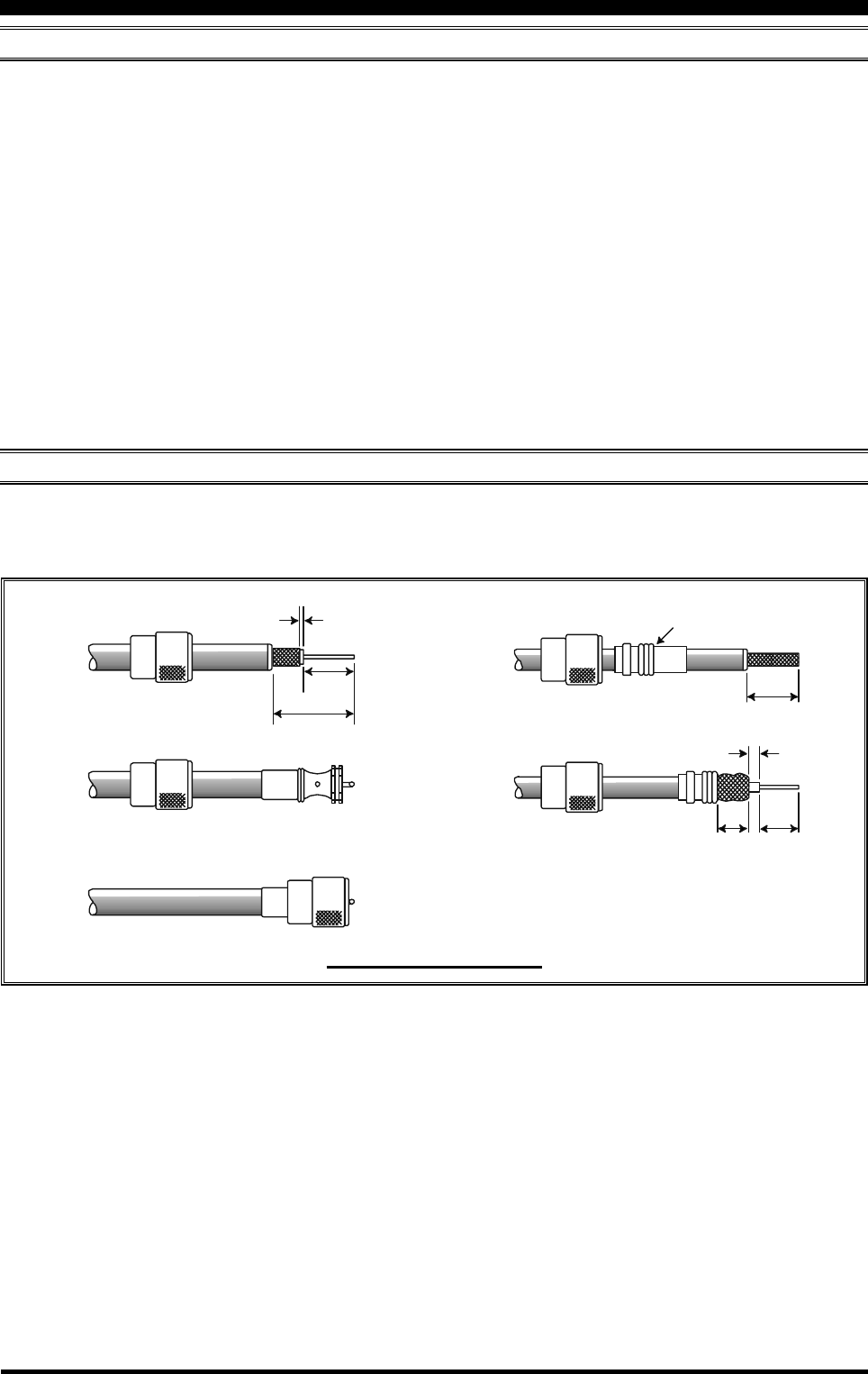
ABOUT COAXIAL CABLE
Use high-quality 50-Ohm coaxial cable for the lead-in to your FTDX5000 transceiver. All efforts at providing an efficient
antenna system will be wasted if poor quality, lossy coaxial cable is used. This transceiver utilizes standard “M” (“PL-259”)
type connectors, except for the “RX OUT” BNC connector.
INSTALLATION AND INTERCONNECTIONS
1/16''
3/4''
1 1/ 8 ''
3/4''
Adapter
1/8''
5/8''3/8''
TYPICAL PL-259 INSTALLATION
Page 9FTDX5000 OPERATING MANUAL
INSTALLATION AND INTERCONNECTIONS
GROUNDING
The FTDX5000 transceiver, like any other HF communications apparatus, requires an effective ground system for maxi-
mum electrical safety and best communications effectiveness. A good ground system can contribute to station efficiency in
a number of ways:
It can minimize the possibility of electrical shock to the operator.
It can minimize RF currents flowing on the shield of the coaxial cable and the chassis of the transceiver; such currents
may lead to radiation which can cause interference to home entertainment devices or laboratory test equipment.
It can minimize the possibility of erratic transceiver/accessory operation caused by RF feedback and/or improper cur-
rent flow through logic devices.
An effective earth ground system may take several forms; for a more complete discussion, see an appropriate RF engineer-
ing text. The information below is intended only as a guideline.
Typically, the ground connection consists of one or more copper-clad steel rods, driven into the ground. If multiple ground
rods are used, they should be positioned in a “V” configuration, and bonded together at the apex of the “V” which is nearest
the station location. Use a heavy, braided cable (such as the discarded shield from type RG-213 coaxial cable) and strong
cable clamps to secure the braided cable(s) to the ground rods. Be sure to weatherproof the connections to ensure many
years of reliable service. Use the same type of heavy, braided cable for the connections to the station ground bus (described
below).
Inside the station, a common ground bus consisting of a copper pipe of at least 25 mm (1”) diameter should be used. An
alternative station ground bus may consist of a wide copper plate (single-sided circuit board material is ideal) secured to the
bottom of the operating desk. Grounding connections from individual devices such as transceivers, power supplies, and
data communications devices (TNCs, etc.) should be made directly to the ground bus using a heavy, braided cable.
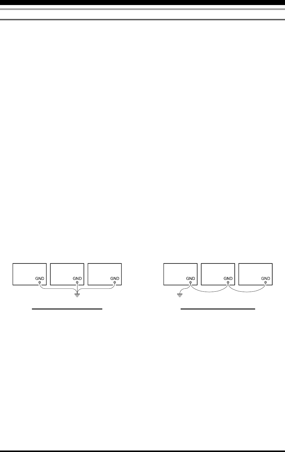
Do not make ground connections from one electrical device to another, and thence to the ground bus. This so-called “Daisy-
Chain” grounding technique may nullify any attempt at effective radio frequency grounding. See the drawing below for
examples of proper grounding techniques.
Inspect the ground system inside and outside of the station, on a regular basis to ensure maximum performance and safety.
Besides following the above guidelines carefully, note that household or industrial gas lines must never be used in an
attempt to establish an electrical ground. Cold water pipes may, in some instances, help in the grounding effort, but gas lines
represent a significant explosion hazard, and must never be used.
PROPER GROUND CONNECTION
Linear
Amplifier
TNC
Transceiver
"Daisy Chain"
Linear
Amplifier
TNC
Transceiver
IMPROPER GROUND CONNECTION
Page 10 FTDX5000 OPERATING MANUAL
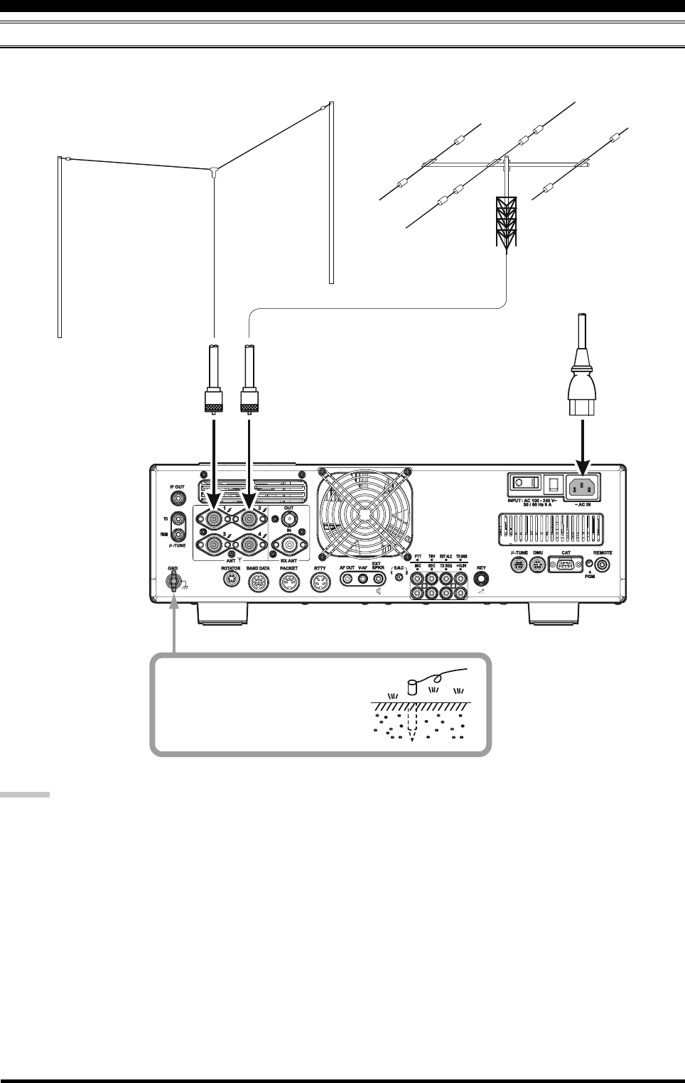
CONNECTION OF ANTENNA AND POWER CABLES
Follow the below illustration and advice regarding the proper connection of antenna coaxial cables, ground cable, and the
AC power cable.
ADVICE:
Do not place the transceiver in a location with direct exposure to sunshine.
Do not place the transceiver in a location exposed to dust and/or high humidity.
Ensure adequate ventilation around the transceiver, to prevent heat build-up and possible reduction of performance due
to high heat.
Do not install the transceiver in a mechanically-unstable location, or where objects may fall onto this product from
above.
To minimize the possibility of interference to home entertainment devices, take all precautionary steps including sepa-
ration of TV/FM antennas from Amateur transmitting antennas to the greatest extent possible. Keep transmitting coaxial
cables separated from cables connected to home entertainment devices.
Ensure that the AC power cord is not subject to undue stress or bending, which could damage the cable or cause it to be
accidentally unplugged from the rear panel AC input jack.
Be absolutely certain to install your transmitting antenna(s) such that they cannot possibly come in contact with TV/FM
radio or other antennas, nor with outside power or telephone lines.
Use a short, thick, braided cable
to connect your station equipment
to the buried ground rod (or alter-
native earth ground system).
INSTALLATION AND INTERCONNECTIONS
ANTENNA "1”
ANTENNA "2”
Page 11FTDX5000 OPERATING MANUAL
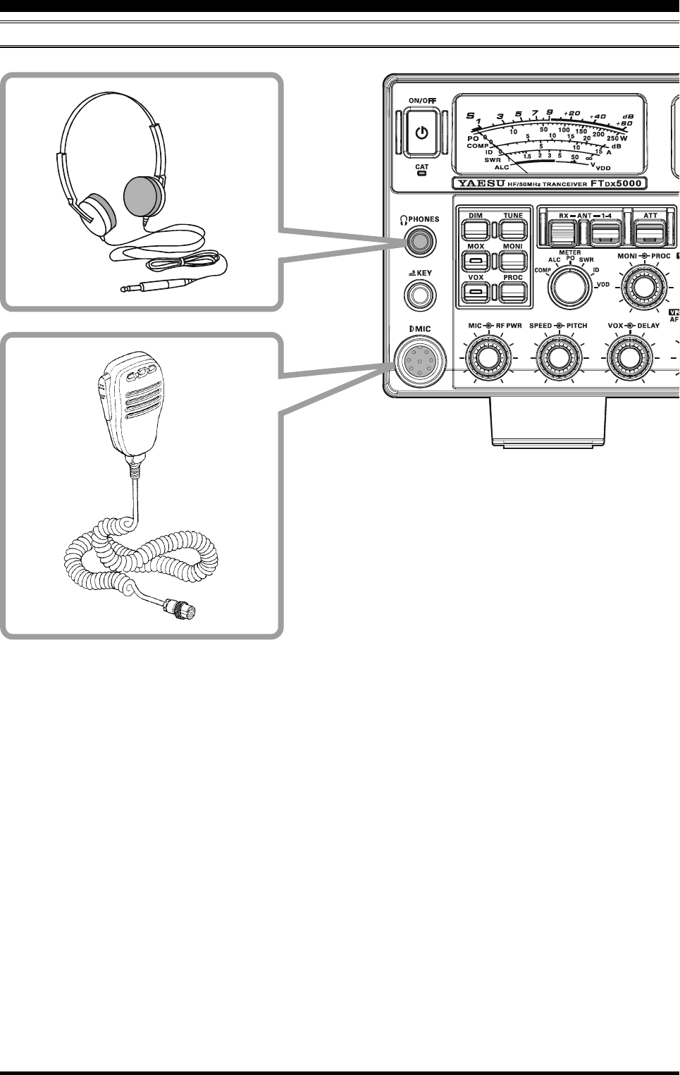
CONNECTION OF MICROPHONE AND HEADPHONE
INSTALLATION AND INTERCONNECTIONS
Page 12 FTDX5000 OPERATING MANUAL
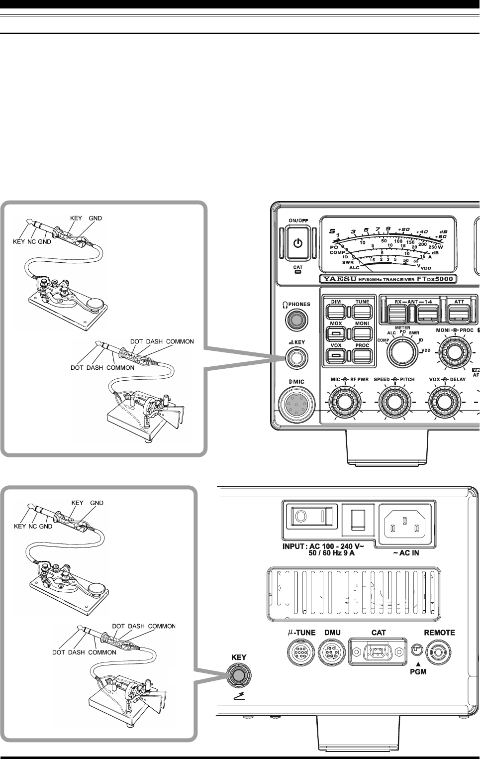
KEY, KEYER, AND COMPUTER-DRIVEN KEYING INTERCONNECTIONS
The FTDX5000 includes a host of features for the CW operator. These functions will be detailed in the “Operation” section
later. An Electronic Keyer is built-in, and two key jacks are provided, one on the front and one on the rear panel, for
convenient connection to keying devices.
The Menu system allows you to configure the front and rear panel KEY jacks according to the device you wish to connect.
For example, you may connect your keyer paddle to the front panel KEY jack, and use Menu item “054 A1A F-TYPE” for
paddle input, while connecting the rear panel KEY jack to the keying line from your personal computer (which emulates a
“straight key” for connection purposes), and configure the rear panel jack using Menu item “056 A1A R-TYPE”.
Both KEY jacks on the FTDX5000 utilize “Positive” keying voltage. Key-up voltage is approximately +5V DC, and key-
down current is approximately 1 mA. When connecting a key or other device to the KEY jacks, use only a 3-pin (“stereo”)
1/4” phone plug; a 2-pin plug will place a short between the ring and (grounded) shaft of the plug, resulting in a constant
“key-down” condition in some circumstances.
INSTALLATION AND INTERCONNECTIONS
Page 13FTDX5000 OPERATING MANUAL
ANT 1
ANT 2
ANT 3
ANT 4
REMOTE
ON
OFF
BAND DATA 1
BAND DATA 2
GND
ALC 2
ALC 1
PTT 2
PTT 1
INPUT 1
INPUT 2
CONTROL
DC48V IN
A
N
T
~
A
C
I
N
A
N
T
1
A
N
T
2
A
N
T
3
I
N
P
U
T
B
A
N
D
D
A
T
A
B
A
N
D
-
D
A
T
A
1
G
N
D
D
C
4
8
V
I
N
C
O
N
T
R
O
L
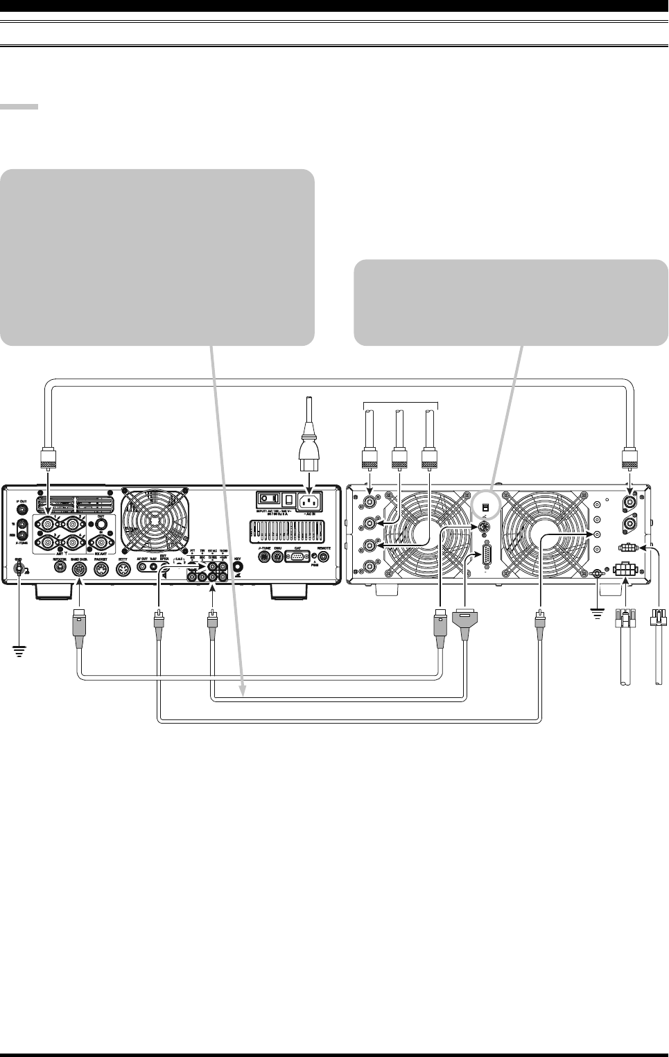
BAND DATA Cable VL-1000
(Supplied with )
V
P
-
1
0
0
0
V
P
-
1
0
0
0
T
X
R
E
Q
E
X
T
A
L
C
B
A
N
D
-
D
A
T
A
2
ALC 1
ALC Cable (Supplied with VL-1000)
CONTROL Cable (Supplied with VL-1000)
ANTENNA Cable To ANTE NN A
VL-1000 LINEAR AMPLIFIER INTERCONNECTIONS
Be sure both the FTDX5000 and VL-1000 are turned off, then follow the installation recommendations contained in the
illustration.
NOTE:
Refer to the VL-1000 Operating Manual for details regarding amplifier operation.
Do not attempt to connect or disconnect coaxial cables when your hands are wet.
INSTALLATION AND INTERCONNECTIONS
About the CONTROL Cable
The VL-1000 may be operated with the
FTDX5000 whether or not the CONTROL Cable
is connected; however, the CONTROL Cable
allows you to tune up the amplifier automatically
by just pressing the [F SET] or [TUNE] key on
the VL-1000, to transmit a carrier for tuning pur-
poses.
To link the FTDX5000 and VL-1000 Power
switches, set the VL-1000 REMOTE switch to
the “ON” position.
Page 14 FTDX5000 OPERATING MANUAL
INSTALLATION AND INTERCONNECTIONS
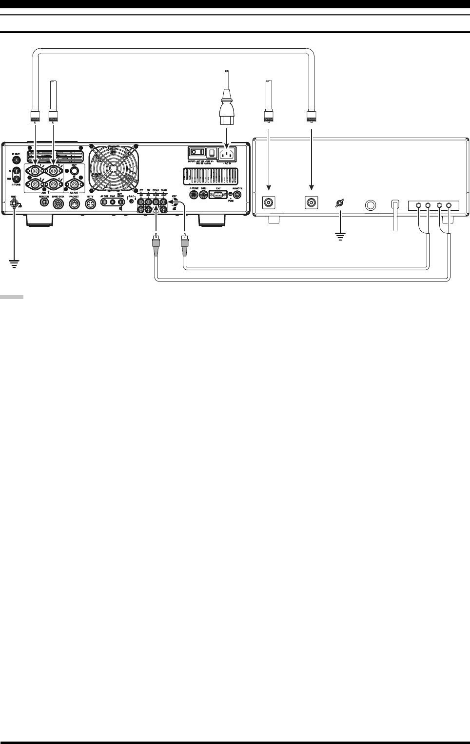
INTERFACING TO OTHER LINEAR AMPLIFIERS
NOTE
The TX/RX switching in the linear amplifier is con-
trolled by switching components in the transceiver. The
relay circuit of the FTDX5000 used for this switching
is capable of switching AC voltage of 100 Volts at up
to 300 mA, or DC voltages of 60 V at 200 mA or 30 V
at up to 1 Amp. To activate the amplifier switching
relay, set Menu item “172 TGEN ETX-GND” to “EN-
ABLE”.
The specified range for ALC voltage to be used with
the FTDX5000 is 0 to –4 Volts DC.
Amplifier systems utilizing different ALC voltages will
not work correctly with the FTDX5000, and their ALC
lines must not be connected if this is the case.
GND
GND
RELAY
ALC
ACFUSEGND
RF IN
RF OUT
ANT 1
~AC IN
ANT 1
ANT 2
INPUT 1
TX GND
GND
GND
EXT ALC
ANTENNA Cable
50 MHz Antenna
HF Antenna
Page 15FTDX5000 OPERATING MANUAL
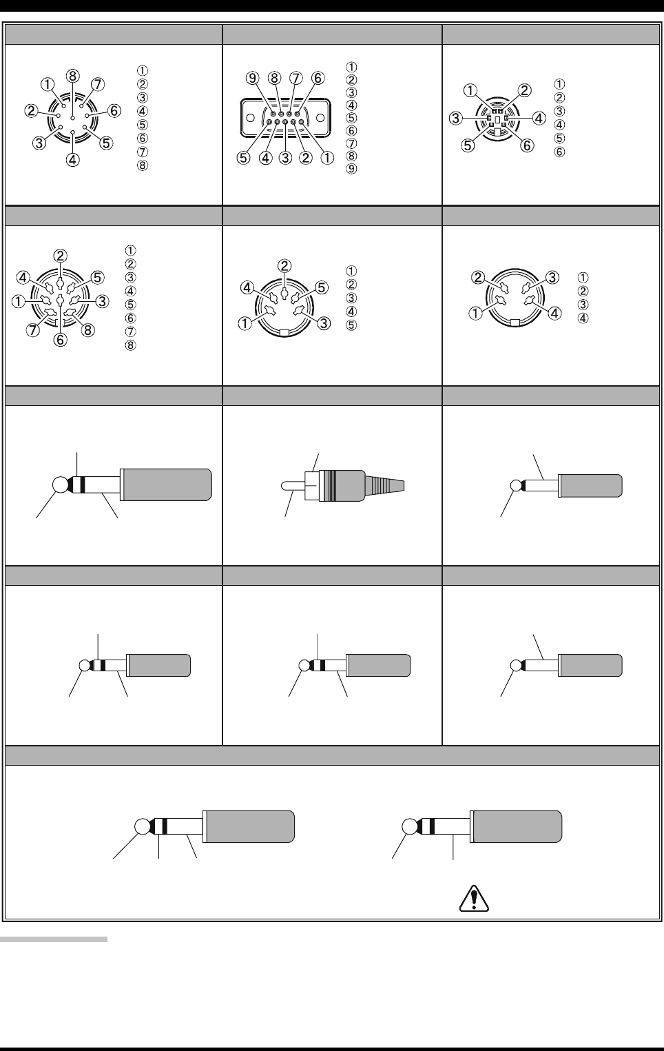
PLUG /CONNECTOR PINOUT DIAGRAMS
IMPORTANT NOTE:
The µ-TUNE and DMU use special connectors for this transceiver. Do not connect any accessory or other device not
specifically approved by Vertex Standard. Failure to observe this precaution may cause damage not covered by the Limited
Warranty on this apparatus.
Do not use
2-conductor type plug
UP
+5V
DOWN
FAST
GND
PTT
MIC GND
MIC
+13V
TX GND
GND
BAND DATA A
BAND DATA B
BAND DATA C
BAND DATA D
TX INH
RTTYBAND DATA
AF OUT
RCA PLUG
KEY
MIC CAT
SIGNAL or ()
+
GND or (-- )-
DATA IN
GND
PACKE T PTT
DATA OUT
BUSY
SHIFT
RX OUT
PTT
GND
EXT SPKR
ROTATOR
PAC K E T
V-AF
PHONE REMOTE
N/A
SERIAL OUT
SERIAL IN
N/A
GND
N/A
RTS
CTS
NC
CW ROTATION
SPEED
DIRECTION
GND
NC
CCW ROTATION
(as viewed from front panel)
(as viewed from rear panel)
DOT DASH COMMON
For Internal Keyer
KEY GND
For Straight Key
(as viewed from rear panel)
(as viewed from rear panel)
(as viewed from rear panel)
(as viewed from rear panel)
VFO-B AUDIO
VFO-A AUDIO GND
VFO-B AUDIO
VFO-A AUDIO GND
VFO-B AUDIO
VFO-A AUDIO GND
GND
SIGNAL
GND
SIGNAL
Page 16 FTDX5000 OPERATING MANUAL
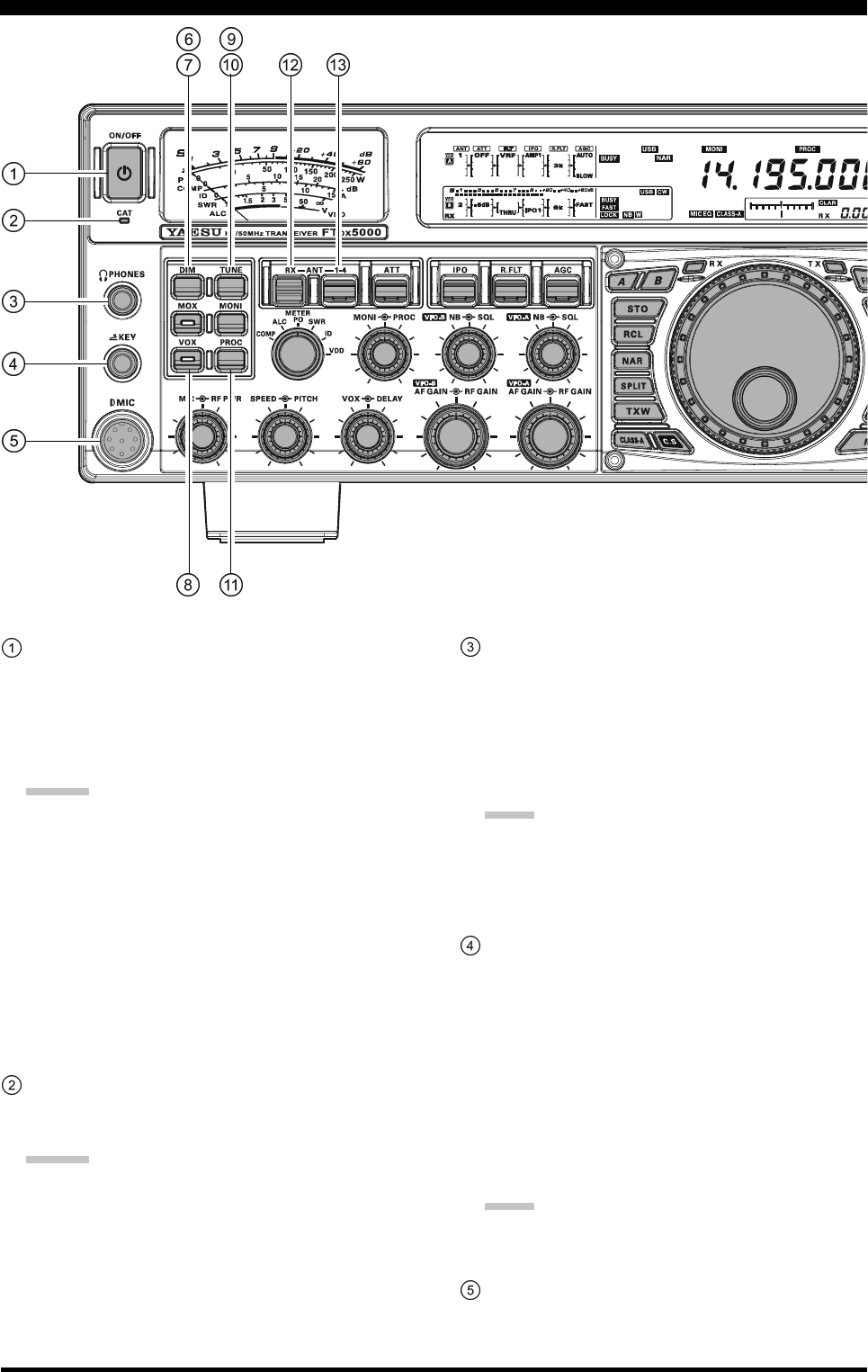
[POWER] Switch
Press this switch in for two seconds to turn the trans-
ceiver on. Alternately, press this switch for two sec-
onds to turn the transceiver off. If the rear panel [MAIN
POWER] switch is set to the “O” (OFF) position, the
front panel [POWER] switch will not function.
ADVICE:
If you press this switch briefly while the transceiver
is turned on, the transceiver audio will be muted
for three seconds.
This is the actual power On/Off switch for turning
the transceiver on. In the MP version, when the rear
panel [MAIN POWER] switch is set to the “I”
(ON) position, power is supplied to the OCXO to
stabilize the reference oscillator. The remainder of
the transceiver is set in a “stand-by” mode. For fur-
ther information on the rear panel [MAIN POWER]
switch, please see the discussion on page 35.
CAT Indicator
This LED indicator will flash red when serial CAT com-
mand signals are being exchanged.
ADVICE:
You may disable the LED CAT command signal flash-
ing function, via Menu item “035 GENE CAT IND.”
See page 124 for details.
PHONES Jack
A 1/4-inch, 3-contact jack accepts either monaural or
stereo headphones with 2- or 3-contact plugs. When a
plug is inserted, the loudspeaker is disabled. With ste-
reo headphones such as the optional YH-77STA, you
can monitor both VFO-A and VFO-B receiver chan-
nels at the same time during Dual Receive operation.
NOTE:
When wearing headphones, we recommend that you
turn the AF Gain levels down to their lowest settings
before turning power on, to minimize the impact of any
audio “pops” on your hearing during switch-on.
KEY Jack
This 1/4-inch, 3-contact jack accepts a CW key or keyer
paddles (for the built-in electronic keyer), or output
from an external electronic keyer. Pinout is shown on
page 15. Key up voltage is 5 V, and key down current
is 1 mA. This jack may be configured for keyer, “Bug,”
“straight key,” or computer interface keying operation
via Menu item “057 A1A F-TYPE” (see page 126).
There is another KEY jack on the rear panel, and it
may be configured independently for Internal Keyer
or pseudo-straight-key operation.
NOTE:
You cannot use a 2-contact plug in this jack (to do so
produces a constant “key down” condition).
Microphone Connector
This 8-pin jack accepts input from a microphone uti-
lizing a traditional YAESU HF-transceiver pinout.
FRONT PANEL CONTROLS & SWITCHES
Page 17FTDX5000 OPERATING MANUAL
[DIM] Switch
Press this button to lower the illumination intensity of
the analog meter and the frequency display. Press it
once more to restore full brightness.
ADVICE:
The following Menu items allow you to configure the
dimming levels of each display independently to cus-
tomize the brightness levels.
008 DISP DIM MTR: for analog meter
009 DISP DIM VFD: for frequency display
010 DISP DIM OLE:SUB DISPLAY windows
011 DISP DIM ELCD: for Spectrum Scope display
of the optional SM-5000 Sta-
tion Monitor
[MOX] Switch
Pressing this button engages the PTT (Push to Talk)
circuit, to activate the transmitter. The LED inside the
button will glow red during transmit. It must be turned
off (the red LED will be off) for reception. This button
replicates the action of the Push to Talk (PTT) switch
on the microphone. When engaging the [MOX] button
or otherwise starting a transmission, be certain you have
either an antenna or 50-Ohm dummy load connected
to the selected Antenna jack.
[VOX] Switch
This button enables automatic voice-actuated transmit-
ter switching in the SSB, AM, and FM modes. While
activated, the LED inside the button glows red. Proper
adjustment of the front panel [VOX] and [DELAY]
knobs will make hands-free voice-actuated operation
possible.
[TUNE] Switch
This is the on/off switch for the FTDX5000’s Auto-
matic Antenna Tuner.
Pressing this button briefly, places the antenna tuner in
line between the transmitter final amplifier and the an-
tenna jack (The “ ” icon will appear in the dis-
play). Reception is not affected.
Pressing this button for 1/2 second, while receiving in
an amateur band, activates the transmitter for a few
seconds while the automatic antenna tuner rematches
the antenna system impedance for minimum SWR. The
resulting setting is automatically stored in one of the
antenna tuner’s 100 memories, for instant automatic
recall later when the receiver is tuned near the same
frequency.
Pressing this button briefly, while the Tuner is engaged,
will take the Automatic Antenna tuner out of the trans-
mit line.
NOTE:
A signal is being transmitted while the tuner is match-
ing the antenna impedance. Therefore, be certain there
is a dummy load or antenna connected to the selected
antenna jack before initiating the tuning sequence.
[MONI] (Monitor) Switch
This button enables the transmit monitor in all modes.
While activated, the “ ” icon appears in the dis-
play. Use the [MONI] knob to adjust the Monitor level.
ADVICE:
The Monitor is highly useful for making adjustments
to the Parametric Equalizer, or other voice character-
istic adjustments, while listening with headphones. The
voice quality heard in the headphones is a “natural”
reproduction of the transmitted audio.
[PROC] (Processor) Switch
This button enables the Speech Processor for SSB
transmission. While activated, the “ ” icon appears
in the display. Adjustment of the Processor level is ac-
complished using the [PROC] knob.
ADVICE:
The Speech Processor uses a compression technique
to increase the average power output. However, if
the [PROC] knob is advanced too far, the increase
in compression becomes counter-productive, and
intelligibility will suffer. We recommend that you
monitor the sound of your signal using the Monitor
(with headphones).
When the optional DMU-2000 Data Management
Unit is connected, you may use the Audio Scope/
Oscilloscope function to help you adjust the set-
ting of the Speech Processor compression level for
optimum performance with your voice and micro-
phone.
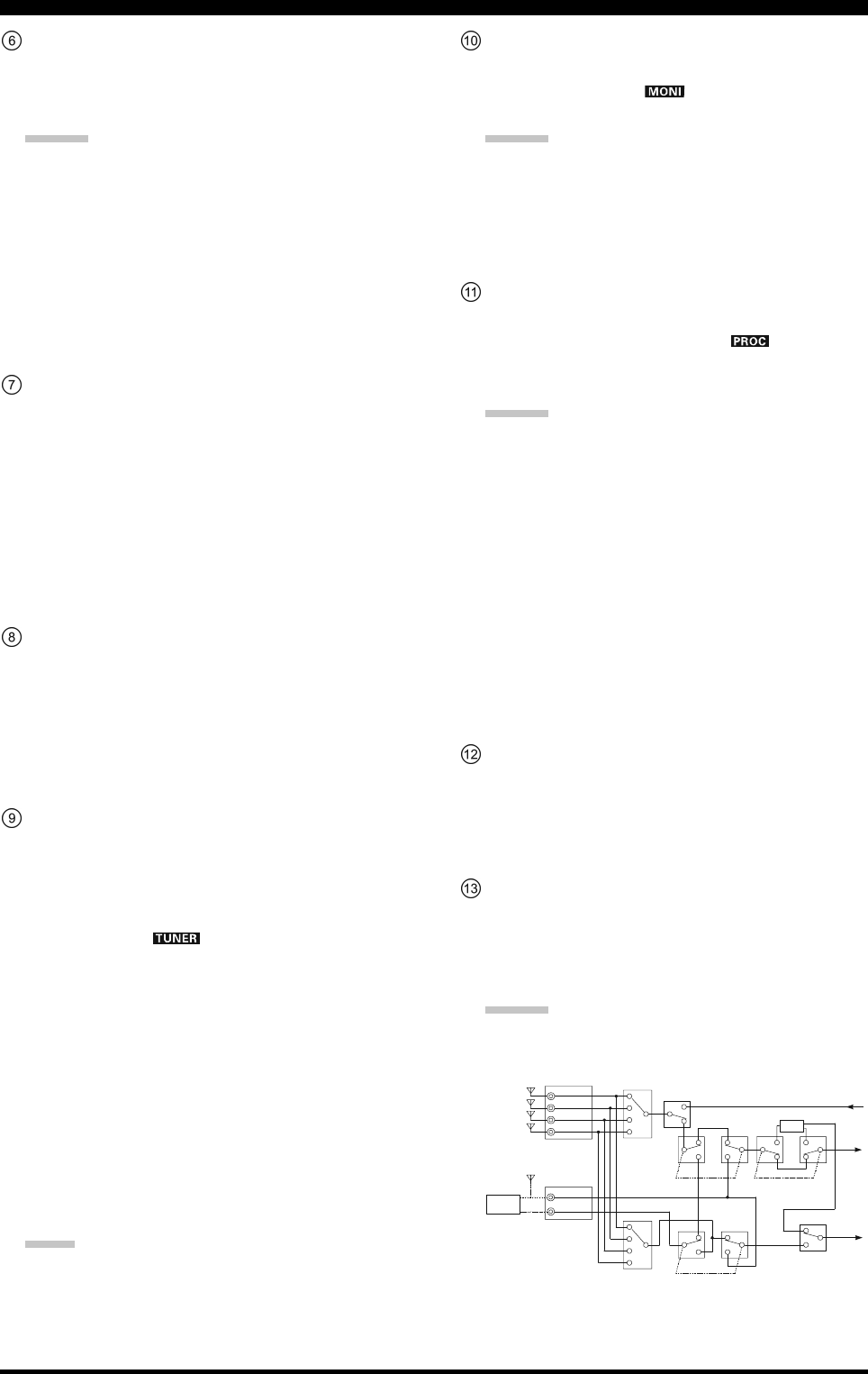
[RX ANT] Switch
Press this button to use an antenna connected to the
RX ANT jack on the rear panel for receive.
The “RX” icon appears in the display when the RX
ANT is used.
[ANT 1-4] Switch
Move this knob up or down to conveniently select one
of the four antenna jacks on the rear panel. The se-
lected antenna jack is indicated in the ANT column of
the Block Diagram Display.
ADVICE:
Press this knob in briefly to quickly select the ANT 1
jack.
FRONT PANEL CONTROLS & SWITCHES
ANTENNA SWITCH
(VFO-A)
ANTENNA SWITCH
(VFO-B)RX ANTENNA SWITCH
(VFO-B)
RX ANTENNA SWITCH
(VFO-A)
TX/RX RELAY Transmitter
Section
VFO-A
Receiver
VFO-B
Receiver
BPF
ANT “1”
ANT “3”
ANT “2”
ANT “4”
RX ANT
RX OUT
Divider
SEPARATE
SEPARATE
Page 18 FTDX5000 OPERATING MANUAL
FRONT PANEL CONTROLS & SWITCHES
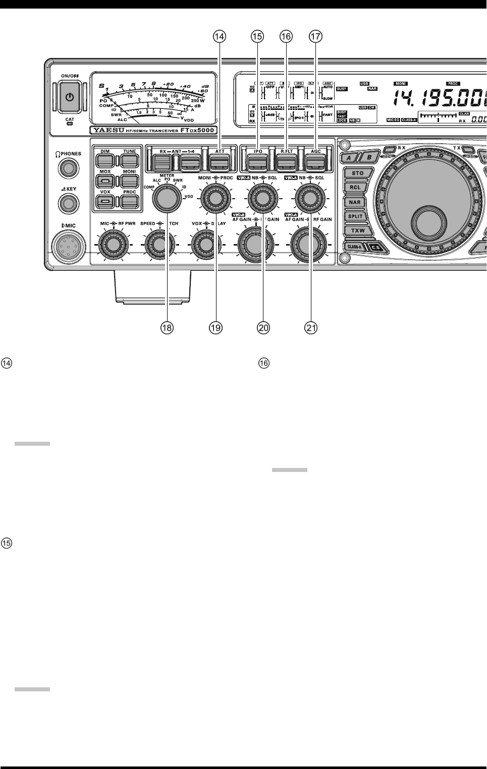
[ATT] Switch
Move this knob up or down to select the degree of
Attenuation to be applied to the receiver input.
Available selections are “–6 dB”, “–12 dB”, “–18 dB”,
or “OFF”. The selected attenuation level appears in
the ATT column of the Block Diagram Display.
ADVICE:
Press this knob in briefly, to quickly turn the at-
tenuation level off.
The Attenuator may be used in conjunction with
the [IPO] switch to provide additional gain reduc-
tion when an extremely strong signal is being re-
ceived.
[IPO]
(I
NTERCEPT
P
OINT
O
PTIMIZATION
)
Switch
Move this knob up or down to select the optimum front
end characteristics of the receiver circuit. Available
selections are “AMP 1”, “AMP 2”, “IPO 1”, or “IPO
2”.
Normally, IPO is set to “AMP1”. If you want to in-
crease the sensitivity, use “AMP2”. When set to
“IPO1”, the IPO performance of the receivers is im-
proved. When set to “IPO2”, the RF preamplifier is
bypassed, yielding direct feed to the first mixer. As a
result, the IPO is improved more.
ADVICE:
Press this knob in briefly to quickly select the
“AMP1” IPO setting.
“IPO 2” can not be selected for VFO-B.
[R.FLT] Switch
Move this knob up or down to select the bandwidth of
the first IF Roofing Filter. Available selections are “300
Hz”, “600 Hz”, “3 kHz”, “6 kHz”, “15 kHz”, or
“AUTO” (“300 Hz” and “600 Hz” are available only
in VFO-A. The “300 Hz” filter is optional, except in
the MP version). The selected bandwidth appears in
the R.FLT column of the Block Diagram Display.
ADVICE:
Press this knob in briefly to quickly select “AUTO”.
Because the roofing filter is in the first IF, the pro-
tection it provides against interference is quite sig-
nificant. When set to “AUTO”, the SSB bandwidth
is 6 kHz, CW is 3 kHz, and FM/RTTY are 15 kHz.
However, on a crowded SSB band, you may wish
to select the 3 kHz filter, for the maximum possible
interference rejection.
Page 19FTDX5000 OPERATING MANUAL
FRONT PANEL CONTROLS & SWITCHES
[AGC] Switch
Move this knob up and down to select the receiver AGC
characteristics (receiver-recovery time). Available se-
lections are FAST, MID, SLOW, or AUTO, and the
selected receiver-recovery time appears in the AGC
column of the Block Diagram Display.
Hold this knob up or down for two seconds to disable
the AGC (for testing or weak-signal reception).
ADVICE:
Press this knob in briefly to quickly select “AUTO”.
If the AGC is disabled by holding the [AGC] knob
up or down, the S-meter will no longer deflect. Ad-
ditionally, you will likely encounter distortion on
stronger signals, as the IF amplifiers and the fol-
lowing stages may be overloaded.
[METER] Switch
This control switch determines the function of the meter
during transmission.
COMP: Indicates the speech compression level (SSB
mode only).
ALC: Indicates the relative ALC voltage.
PO: Indicates the average power output level.
SWR: Indicates the Standing Wave Ratio (Forward:
Reflected).
ID: Indicates the final amplifier drain current.
VDD: Indicates the final amplifier drain voltage.
[MONI] [PROC] Knobs
[MONI] Knob
The inner [MONI] knob adjusts the audio level of
the transmit RF monitor during transmission (rela-
tive to the AF GAIN control), when activated by
the [MONI] button.
[PROC] Knob
The outer [PROC] knob sets the compression (in-
put) level of the transmitter Speech Processor in
the SSB, AM, and FM modes, when activated by
the [PROC] button.
ADVICE:
The relative compression level of the Speech Pro-
cessor will show for 3-seconds in the lower right
corner of the Main Display whenever the outer
[PROC] knob is turned.
Alternately, the 3-second display feature may be
changed to show in the SUB DISPLAY-
III
win-
dow via Menu item “018 DISP INDI”. Addition-
ally, you may disable the 3-second display feature
via Menu item “017 DISP LVL IND” See page
122 for details.
(VFO-B) [NB][SQL] Knobs
[NB] Knob
The inner [NB] knob adjusts the noise blanking
level when the VFO-B (analog) IF noise blanker is
activated by pressing the [NB] button.
[SQL] Knob
The outer [SQL] knob sets the signal level thresh-
old at which the VFO-B receiver audio is muted, in
all modes. The squelch is very useful during local
rag-chews, to eliminate noise between incoming
transmissions. This control is normally kept fully
counter-clockwise (off), except when scanning and
during FM operation.
(VFO-A) [NB] [SQL] Knobs
[NB] Knob
The inner [NB] knob adjusts the noise blanking
level when the VFO-A (analog) IF noise blanker is
activated by pressing the [NB] button.
[SQL] Knob
The outer [SQL] knob sets the signal level thresh-
old at which the VFO-A receiver audio is muted, in
all modes. The squelch is very useful during local
rag-chews, to eliminate noise between incoming
transmissions. This control is normally kept fully
counter-clockwise (off), except when scanning and
during FM operation.
Page 20 FTDX5000 OPERATING MANUAL
FRONT PANEL CONTROLS & SWITCHES
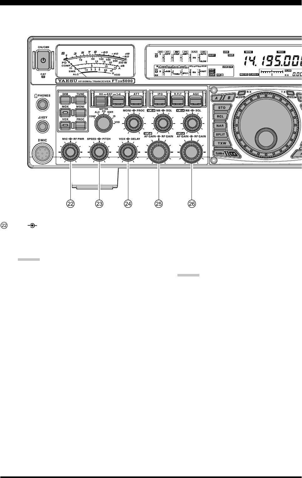
[MIC] [RF PWR] Knobs
[MIC] Knob
The inner [MIC] knob adjusts the microphone in-
put level for (non-processed) SSB transmission.
ADVICE:
Adjust the MIC Gain while speaking in a some-
what-louder-than-normal voice. Watch the ALC
level and adjust the MIC Gain so that the ALC
indication reaches just to the right edge of the
scale. Then, when you speak in a normal voice
level, you will not over-driving the mic ampli-
fier stage.
The relative Microphone Gain level will show
for 3-seconds in the lower right corner of the
Main Display whenever the inner [MIC] knob
is turned.
Alternately, the 3-second display feature may
be changed to show in the SUB DISPLAY-
III
window via Menu item “018 DISP INDI”. Ad-
ditionally, you may disable the 3-second dis-
play feature via Menu item “017 DISP LVL
IND” See page 122 for details.
[RF PWR] Knob
The outer [RF PWR] knob is the main RF Power
output control for the transceiver. It is active in all
operating modes. Clockwise rotation increases the
power output. Adjust this control for the desired
power output from the FTDX5000.
ADVICE:
The RF Power output will show for 3 seconds in
the lower right corner of the Main Display when-
ever the outer [RF PWR] knob is turned.
Alternately, the 3-second display feature may be
changed to show in the SUB DISPLAY-
III
win-
dow via Menu item “018 DISP INDI”. Addition-
ally, you may disable the 3-second display feature
via Menu item “017 DISP LVL IND” See page
122 for details.
Page 21FTDX5000 OPERATING MANUAL
FRONT PANEL CONTROLS & SWITCHES
[SPEED] [PITCH] Knobs
[SPEED] Knob
The inner [SPEED] knob adjusts the keying speed
of the internal CW keyer (4 ~ 60 WPM). Clock-
wise rotation increases the sending speed.
The keying speed will show for 3 seconds in the
lower right corner of the Main Display while the
[KEYER] button is held depressed for more than
one second.
ADVICE:
The keying speed will show for 3 seconds in the
lower right corner of the Main Display whenever
the outer [SPEED] knob is turned.
Alternately, the 3-second display feature may be
changed to show in the SUB DISPLAY-
III
win-
dow via Menu item “018 DISP INDI”. Addition-
ally, you may disable the 3-second display feature
via Menu item “017 DISP LVL IND” See page
122 for details.
[PITCH] Knob
The outer [PITCH] knob selects your preferred CW
tone pitch (from 300 ~ 1050 Hz, in 50 Hz incre-
ments). The TX sidetone, the receiver IF passband,
and the display offset from the BFO (carrier) fre-
quency are all affected simultaneously. The Pitch
control setting also affects the operation of the CW
Tuning Indicator, as the center frequency of the CW
Tuning Indicator will follow the setting of this con-
trol.
ADVICE:
The CW tone pitch frequency will show for 3 sec-
onds in the lower right corner of the Main Display
whenever the outer [SPEED] knob is turned.
Alternately, the 3-second display feature may be
changed to show in the SUB DISPLAY-
III
win-
dow via Menu item “018 DISP INDI”. Addition-
ally, you may disable the 3-second display feature
via Menu item “017 DISP LVL IND” See page
122 for details.
[VOX] [DELAY] Knobs
[VOX] Knob
The inner [VOX] knob sets the level of microphone
audio needed to activate the transmitter during voice
operation when the [VOX] switch is actuated.
[DELAY] Knob
The outer [DELAY] knob sets the hang time of the
VOX circuit for voice operation, and the keying
delay for CW operation.
For voice operation, this knob sets the hang time,
between the moment you stop speaking, and the
time the transmit is switched back to receive. For
smooth operation, adjust the VOX so the transmit
switches to receive when your comments have
ended.
For CW, this knob sets the automatic transmit to
receive keying delay for “Semi-break-in” operation.
Adjust this just long enough to prevent the receiver
from being restored during word spaces at your
preferred sending speed.
ADVICE:
The hang time of the VOX circuit will show for 3
seconds in the lower right corner of the Main Dis-
play whenever the outer [SPEED] knob is turned.
Alternately, the 3-second display feature may be
changed to show in the SUB DISPLAY-
III
win-
dow via Menu item “018 DISP INDI”. Addition-
ally, you may disable the 3-second display feature
via Menu item “017 DISP LVL IND” See page
122 for details.
(VFO-B)[AF GAIN] [RF GAIN] Knobs
[AF GAIN] Knob
The inner [AF GAIN] knob sets the audio level of
the VFO-B receiver. Typically, you will operate with
this control set between the 9 o’clock and 10 o’clock
positions.
[RF GAIN] Knob
The outer [RF GAIN] knob sets the gain of the RF
and IF amplifier stages of the VFO-B receiver. This
control is normally left in the fully clockwise posi-
tion.
(VFO-A) [AF GAIN] [RF GAIN] Knobs
[AF GAIN] Knob
The inner [AF GAIN] knob sets the audio level of
the VFO-A receiver. Typically, you will operate with
this control set between the 9 o’clock and 10 o’clock
positions.
[RF GAIN] Knob
The outer [RF GAIN] knob sets the gain of the RF
and IF amplifier stages of the VFO-A receiver. This
control is normally left in the fully clockwise posi-
tion.
Page 22 FTDX5000 OPERATING MANUAL
FRONT PANEL CONTROLS & SWITCHES
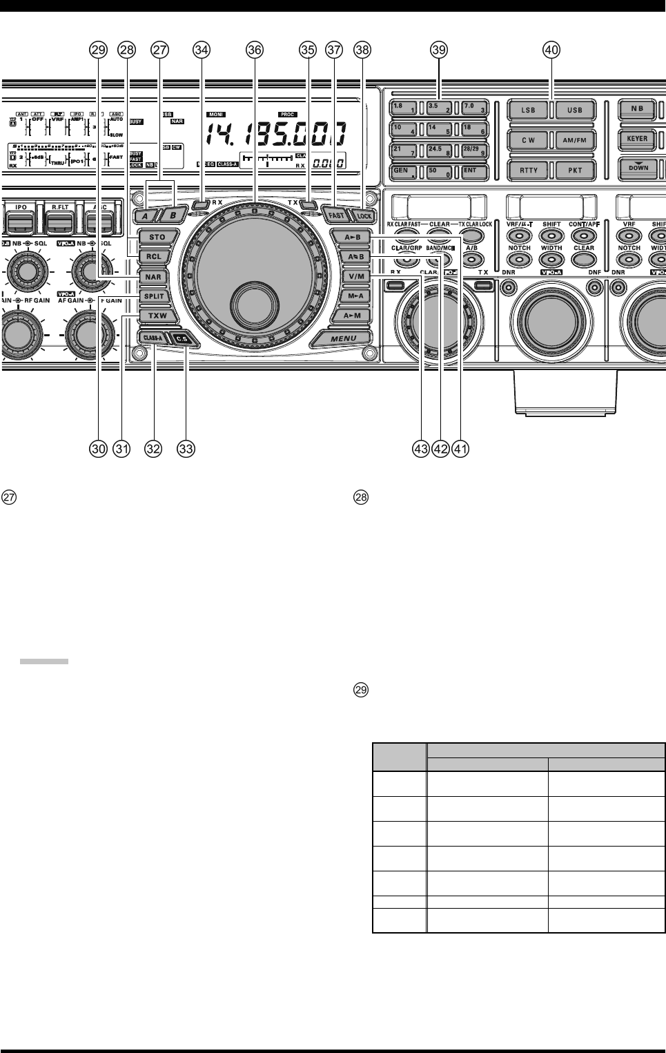
[A], [B] Switches
Pressing the [A] or [B] button will illuminate the re-
spective switch, and allow adjustment of the major
functions (such as mode and band selection etc) on the
VFO-A or VFO-B receiver. Usually, the [A] button will
glow red, and the VFO-A functions may be adjusted.
Similarly, pressing the [B] button will cause its indica-
tor glow orange, signifying the VFO-B functions may
be adjusted.
ADVICE:
The [A]/[B] switches affect the following functions:
[RX ANT] switch
[ANT 1-4] switch
[ATT] switch
[IPO] switch
[R.FLT] switch
[AGC] switch
[NAR] switch
[BAND] switches
[MODE] switches
[NB] switch
[RX ANT] switch
QMB (Quick Memory Bank) Switches
[STO] (Store) Button
Pressing this button, copies the operating informa-
tion for frequency, mode, and bandwidth, into con-
secutive QMB Memories. Repeater shift/direction,
frequency and CTCSS functions, are also copied
in the FM mode.
[RCL] (Recall) Button
Pressing this button recalls one of the five Quick
Memory Bank memories for operation.
[NAR] (Narrow) Switch
This button is used to set the DSP (digital) filters to
narrow bandwidths. The default values are as follows:
:You may enable the [WIDTH] knob to adjust the
bandwidth.
OFF
2.4 kHz
(1.8 kHz - 4.0 kHz / 16 steps)
2.4 kHz
(500 Hz - 2.4 kHz / 7 steps)
500 Hz
(500 Hz - 2.4 kHz / 7 steps)
500 Hz
(500 Hz - 2.4 kHz / 7 steps)
25 kHz
(±5.0 kHz Deviation)
9 kHz
25 kHz
(±5.0 kHz Deviation)
ON
1.8 kHz
(200 Hz - 1.8 kHz / 9 steps)
500 Hz
(50 Hz - 500 Hz / 10 steps)
300 Hz
(50 Hz - 500 Hz / 10 steps)
300 Hz
(50 Hz - 500 Hz / 10 steps)
12.5 kHz
(±2.5 kHz Deviation)
6 kHz
12.5 kHz
(±2.5 kHz Deviation)
MODE
LSB/USB
CW
RTTY
(LSB)
PKT
(LSB/USB)
PKT
(FM)
AM
FM
NAR SWITCH
Page 23FTDX5000 OPERATING MANUAL
FRONT PANEL CONTROLS & SWITCHES
[SPLIT] Switch
Press this button briefly to activate split frequency op-
eration between the VFO-A receiver and the VFO-B,
transmit. Press and hold in this button for two seconds
to engage the “Quick Split” feature, whereby VFO-B
will automatically be set to a frequency 5 kHz higher
than the VFO-A frequency with the same operating
mode, and the transceiver will be placed in the Split
mode.
[TXW] (TX Watch) Switch
Press and hold this button to monitor the transmit fre-
quency when split frequency operation is engaged.
Release the button to return to normal operation.
[CLASS-A] Switch
Press this button to engage the Class-A transmit capa-
bility. The power output will be reduced to a maxi-
mum of 75 Watts. However, Class-A operation pro-
vides an ultra-clean SSB waveform. When Class-A op-
eration is engaged, the “CLASS-A” icon appears in
the display. Press this button once more to return to
Class-AB operation at a maximum power output of 200
Watts; the “CLASS-A” icon disappears to confirm
Class-AB operation.
ADVICE:
You may adjust the bias level between “Class-AB” and
“Class-A” via Menu item “169 TGEN BAIS”. See
page 136 for details.
[C.S] Switch
Press this button briefly to recall a favorite Menu Se-
lection directly.
To assign a Menu selection as the short-cut, press the
[MENU] button to enter the Menu, then select the Menu
item. Now press and hold in the [C.S] button for two
seconds to lock the selected Menu item as the short-cut.
(VFO-A)[RX] Indicator/Switch
Press this button to engage the VFO-A receiver; the
button will glow green when the VFO-A receiver is
active.
When the VFO-A receiver is active, pressing this but-
ton briefly will mute the receiver, and the indicator will
blink. Pressing the button once more will restore re-
ceiver operation, and the indicator will glow green
steadily.
(VFO-A)[TX] Indicator/Switch
When this button is pressed, the button indicator will
glow red and the transmitter frequency and mode will
be controlled by VFO-A (subject to any Clarifier off-
set, of course).
ADVICE:
If this indicator is not illuminated, it means that VFO-
B TX has been selected (In this case, The VFO-B TX
indicator will glow red and the transmitter frequency
and mode will be controlled by VFO-B).
OPERATING MODE
LSB/USB/CW/RTTY/PKT(SSB)
AM/FM/PKT(FM)
Numbers in parentheses indicate steps when the [FAST] button is On.
1 STEP
10 Hz (100 Hz)
100 Hz (1 kHz)
1 DIAL ROTATION
10 kHz (100 kHz)
100 kHz (1 MHz)
Main Tuning Dial Knob
This large knob adjusts the operating frequency of
VFO-A or a recalled memory. Clockwise rotation of
the knob increases the frequency. Default tuning in-
crements are 10 Hz (100 Hz in AM and FM modes);
when the [FAST] button is pressed, the tuning steps
increase. The available steps are:
ADVICE:
The tuning steps for the Main Tuning Dial knob
are set, at the factory, to 10 Hz per step. Via Menu
item “142 TUN DIAL STEP”, however, you may
change this setting from 10 Hz to 5 Hz or 1 Hz
instead. When the [FAST] button is pressed, the
tuning step change to 100 Hz.
You may lock the Main Tuning Dial knob in the
AM and FM mode via Menu items “147 TUN AM
D.LCK” and “148 TUN FM D.LCK”.
[FAST] Switch
Pressing this button will change the VFO-A tuning
step to 100 Hz.
When this function is activated, the “ ” icon ap-
pears in the display.
[LOCK] Switch
This button toggles locking of the Main Tuning Dial
knob, to prevent accidental frequency changes. When
the button is active, the Main Tuning Dial knob can
still be turned, but the VFO-A frequency will not
change, and the “ ” icon appears in the display.
[BAND] Keys
These buttons allow one-touch selection of the desired
amateur band (1.8 ~ 50 MHz).
What’s more, these buttons may be used for direct en-
try of a desired operating frequency during VFO op-
eration.
[MODE] Switches
Pressing one of these buttons, selects the operating
mode. Repeated presses of a particular switch will
toggle to the alternate mode, or step through the avail-
able selections, as shown in the chart below.
SWITCH
LSB
USB
CW
AM/FM
RTTY
PKT
VARIABLE MODE SELECTION
LSB
USB
CW (LSB) CW (USB)
AM FM
RTTY (LSB) RTTY (USB)
PKT (LSB)PKT (USB)PKT (FM) .....
Page 24 FTDX5000 OPERATING MANUAL
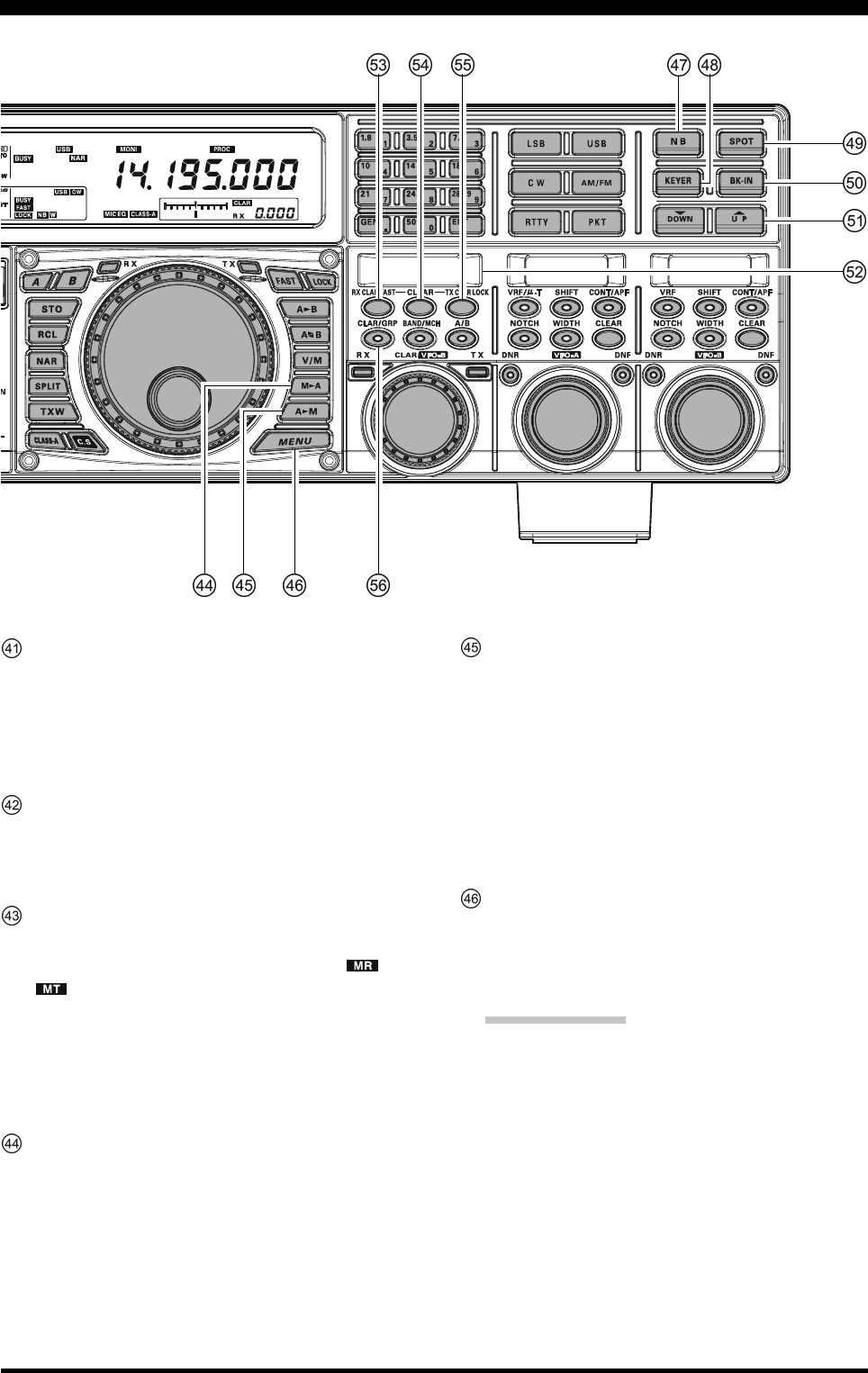
[A
B] Switch
Press this button briefly to transfer data from the VFO-
A frequency (or a recalled memory channel) to VFO-
B, overwriting any previous contents in VFO-B. Use
this button to set both VFO-A and VFO-B receivers to
the same frequency and mode.
[A
B] Switch
Pressing this button briefly, exchanges the contents of
the VFO-A (or a recalled memory channel) and the
VFO-B.
[V/M] Switch
This button toggles VFO-A receiver operation between
the memory system and the VFO. Either “ ” or
“” will be displayed under the main frequency
display field to indicate the current selection. If you
have tuned off of a Memory channel frequency (MT),
pressing this button returns the display to the original
memory contents (MR), and pressing it once more re-
turns operation to VFO-A (no icon).
[M
A] Switch
Press this button briefly, to display the contents of the
currently-selected memory channel for three seconds.
Holding this button in for 2 seconds copies the data
from the currently-selected memory to VFO-A, as two
beeps sound. Previous data in VFO-A will be over-
written.
[A
M] Switch
Pressing and holding in this button for 1/2 second (un-
til the double beep), copies the current operating data
from VFO-A into the currently selected memory chan-
nel, overwriting any previous data stored there. See
page 102 for details.
Also, pressing and holding in this button after recall-
ing a memory, without first retuning, causes the memory
channel to be “masked,” and repeating the process re-
stores the masked memory.
[MENU] Switch
This button is used to access the Menu system, for con-
figuring various transceiver characteristics. Menu op-
eration is described in detail, in this manual, begin-
ning on page 116.
IMPORTANT NOTE:
Pressing this button briefly activates the Menu, and
the Menu items will appear on the SUB DISPLAY
windows. Once you are finished, you must press and
hold in the [MENU] button for two seconds to save
any configuration changes (briefly press the [MENU]
button to exit without saving the changes).
FRONT PANEL CONTROLS & SWITCHES
Page 25FTDX5000 OPERATING MANUAL
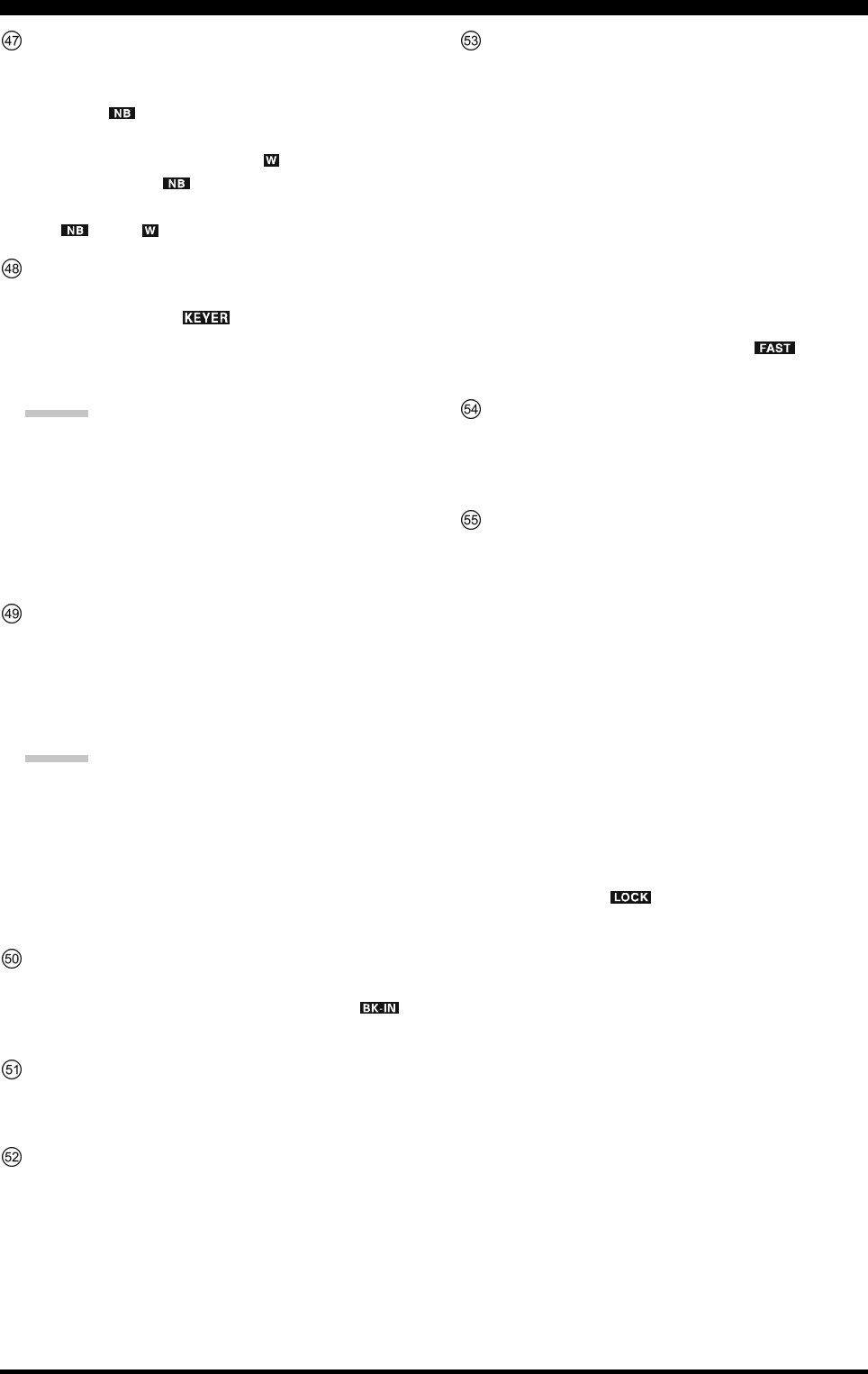
[NB] Switch
This button turns the IF Noise Blanker on and off.
Press this button briefly to reduce a short-duration pulse
noise; the “ ” icon will appear in the display.
Press this button once more to reduce a longer-dura-
tion man-made pulse noise; the “ ” icon will appear
at the right of the “ ” icon.
Press this button again to disable the noise blanker;
the “ ” and “ ” icon will disappear.
[KEYER] Switch
This button toggles the internal CW keyer on and off.
While activated, the “ ” icon appears in the dis-
play. The keyer sending speed is adjusted via the front
panel [SPEED] knob, and the CW Hang Time is ad-
justed via the front panel [DELAY] knob.
ADVICE:
When this button is held for more than one second, the
keying speed will be displayed in the lower right cor-
ner of the Main Display until the button is released.
Alternately, the 3-second display feature may be
changed to show in the SUB DISPLAY-
III
window
via Menu item “018 DISP INDI”. See page 122 for
details.
[SPOT] Switch
This button turns on the CW receiver spotting tone; by
matching the SPOT tone to that of the incoming CW
signal (precisely the same pitch), you will be “zero
beating” your transmitted signal with the frequency of
the other station.
ADVICE:
The offset tone frequency will be displayed in the lower
right corner of the Main Display when this button is
pressed.
Alternately, the 3-second display feature may be
changed to show in the SUB DISPLAY-
III
window
via Menu item “018 DISP INDI”. See page 122 for
details.
[BK-IN] Switch
This button turns the CW break-in capability on and
off. While the CW break-in is activated, the “ ”
icon appears in the display.
[(DOWN)]/[(UP)] Switches
These buttons adjust the operating frequency of the
VFO or a recalled memory in 100 kHz steps.
SUB DISPLAY-I
This OLED (Organic Light Emitting Diode) display
shows the VFO-B frequency, and it indicates the Menu
List while the Menu Mode is active.
[RX CLAR(FAST)] Switch
The function of this button differs with the setting of
the [A/B] button (described later).
When the LED in the [A/B] button is turned off, press-
ing this button activates the RX Clarifier, to allow off-
setting the VFO-A receiving frequency temporarily.
Press this button once more to return the Main receiver
to the frequency shown on the main frequency display
field; the Clarifier offset will still be present, though,
in case you want to use it again. To cancel the Clarifier
offset, press the [CLEAR] button.
When [A/B] button glows orange, pressing this but-
ton will change the VFO-B tuning step to 100 Hz.
When this function is activated, the “ ” icon ap-
pears in the display.
[CLEAR] Switch
Pressing this button clears out any frequency offset you
have programmed into the Clarifier register (thereby
setting the offset to “Zero”).
[TX CLAR/LOCK] Switch
The function of this button is changed by the setting of
the [A/B] button (described later).
When the [A/B] button is turned off, pressing the [TX
CLAR/LOCK] button activates the TX Clarifier, to
allow offsetting the VFO-A transmit frequency tempo-
rarily. Press the button once more to return the trans-
mitter to the VFO-A frequency shown on the main fre-
quency display field; the Clarifier offset will still be
present, though, in case you want to use it again. To
cancel the Clarifier offset, press the [CLEAR] button.
When the [A/B] button glows orange, the [TX CLAR/
LOCK] button toggles locking of the [CLAR(VFO-
B)] knob, to prevent accidental frequency changes.
When the lock is active, the [CLAR(VFO-B)] knob
can still be turned, but the VFO-B frequency will not
change, and the “ ” icon appears in the display.
FRONT PANEL CONTROLS & SWITCHES
Page 26 FTDX5000 OPERATING MANUAL
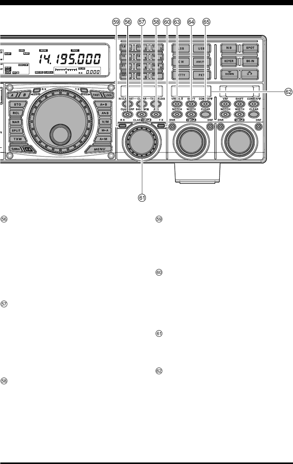
[CLAR/GRP] Switch
This button has two functions.
Press this button briefly, the [CLAR/VFO-B] knob
will be enabled as an “offset tuning” control to allow
tuning away from the VFO-A frequency, and the
[CLAR/GRP] button will glow red.
Pressing and holding this button for one second, al-
lows you to select the memory group using the
[CLAR(VFO-B)] knob, and the [CLAR/GRP] but-
ton will glow yellow.
[BAND(MCH)] Switch
This button has two functions.
Pressing this button briefly, enables the [CLAR(VFO-
B)] knob to select the VFO-A operating Amateur Band.
The [CLAR/GRP)] button glows red.
Pressing and holding this button for one second, al-
lows you to select the memory channel using the
[CLAR(VFO-B)] knob, and the [CLAR/GRP] but-
ton is glows yellow.
[A/B] Switch
This button switches the actions of the [CLAR(VFO-
B)] knob between VFO-A and VFO-B.
Pressing this button once causes the button to glows
yellow; in this case, rotation of the [CLAR(VFO-B)]
knob affects operation on VFO-B (tuning, etc.). Press-
ing this button once more causes the button to turn off;
in this instance, rotation of the [CLAR(VFO-B)] knob
affects operations associated with the VFO-A (Clari-
fier function, etc.).
(VFO-B)[RX] Indicator/Switch
This is the button that turns the VFO-B receiver “On”
and “Off”. When the VFO-B receiver is active, the
button will glow green. Pressing this button again will
disable VFO-B receiver, and the imbedded green LED
will turn off.
(VFO-B)[TX] Indicator/Switch
This button turns the VFO-B transmitter “On” and
“Off”. When this button is pressed, it will glow red
and VFO-B will control the transmitter frequency and
mode. Pressing this button once more will transfer fre-
quency/mode control back to VFO-A, and the red LED
in the button will turn off.
[CLAR(VFO-B)] Knob
The function of this knob differs according to the set-
tings of the three switches located above the knob. See
the next page for details.
SUB DISPLAY-II
This OLED (Organic Light Emitting Diode) display
shows the characteristics of the VFO-A receiver DSP
functions selected by five of the buttons located below
of this display. The (VFO-A)[SELECT] knob located
below this window is an adjustment knob for the func-
tion displayed in this window. Alternately, when the
Menu Mode is activated, this OLED displays the se-
lected Menu item.
FRONT PANEL CONTROLS & SWITCHES
Page 27FTDX5000 OPERATING MANUAL
FRONT PANEL CONTROLS & SWITCHES
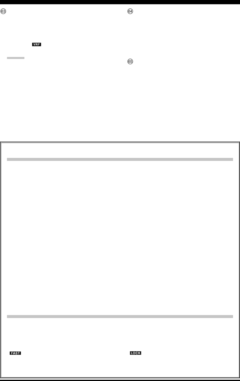
Clarifier Operation
When the [CLAR/GRP] button is pressed briefly, the
imbedded LED in the button will glow red, and the
[CLAR(VFO-B)] knob may be used to program an
offset of up to ± 9.999 kHz from the VFO-A frequency.
However, this offset is only applied to the receive or
transmit frequency if the [RX CLAR/FAST] button
and/or [TX CLAR/LOCK] button, respectively, have
been pushed.
To apply the programmed frequency offset to the Re-
ceive frequency, press the [RX CLAR/FAST] button
briefly. To return to the VFO-A frequency, without the
offset, press the [RX CLAR/FAST] button once more.
To apply the programmed frequency offset to the Trans-
mit frequency, press the [TX CLAR/LOCK] button
briefly. To return the transmitter to the VFO-A fre-
quency, without the offset, press the [TX CLAR/
LOCK] button once more.
To reset the Clarifier frequency offset to “0”, press the
[CLEAR] button.
BAND Up / Down Control
When the [BAND/MCH] button is pressed briefly, the
LED in the button will glow red, and enable the use of
the [CLAR(VFO-B)] knob to select the desired ama-
teur band. If you have engaged the “My Bands” fea-
ture via Menu #145, the [CLAR(VFO-B)] knob will
select just from the amateur bands that you have in-
cluded in the “My Bands” list.
Memory Channel / Memory Group Control
Press and hold in the [BAND/MCH] button for two
seconds, the LED in the button will glow yellow, and
the [CLAR(VFO-B)] knob may be used to select the
desired Memory Channel.
Press and hold in the [CLAR/GRP] button for two
seconds, the LED in the button will glow yellow, and
you may use the [CLAR(VFO-B)] knob to select the
desired Memory Group.
[CLAR(VFO-B)] Knob Functions
When the LED in the [A/B] button is turned “off”
In this case, the [CLAR(VFO-B)] knob is used for Clarifier tuning, as well as Up/Down selection of the Amateur
band, Memory Channels, 1 MHz tuning steps, or Memory Groups.
VFO-B FAST Tuning
When the [RX CLAR/FAST] button is pressed, the
“” icon appears in the display, and the VFO-B
tuning step changes to 100 Hz. Press the [RX CLAR/
FAST] button once more to return to the normal tun-
ing rate.
When the LED in the [A/B] button glows orange
When the [A/B] button is pressed, the LED in the button will glow orange, and the [CLAR(VFO-B)] knob will
control functions associated with the VFO-B frequency control register.
VFO-B Dial Lock
When the [TX CLAR/LOCK] button is pressed, the
“” icon appears in the display, and the
[CLAR(VFO-B)] knob is locked. Press the [RX
CLAR/FAST] button once more to disable the lock
feature.
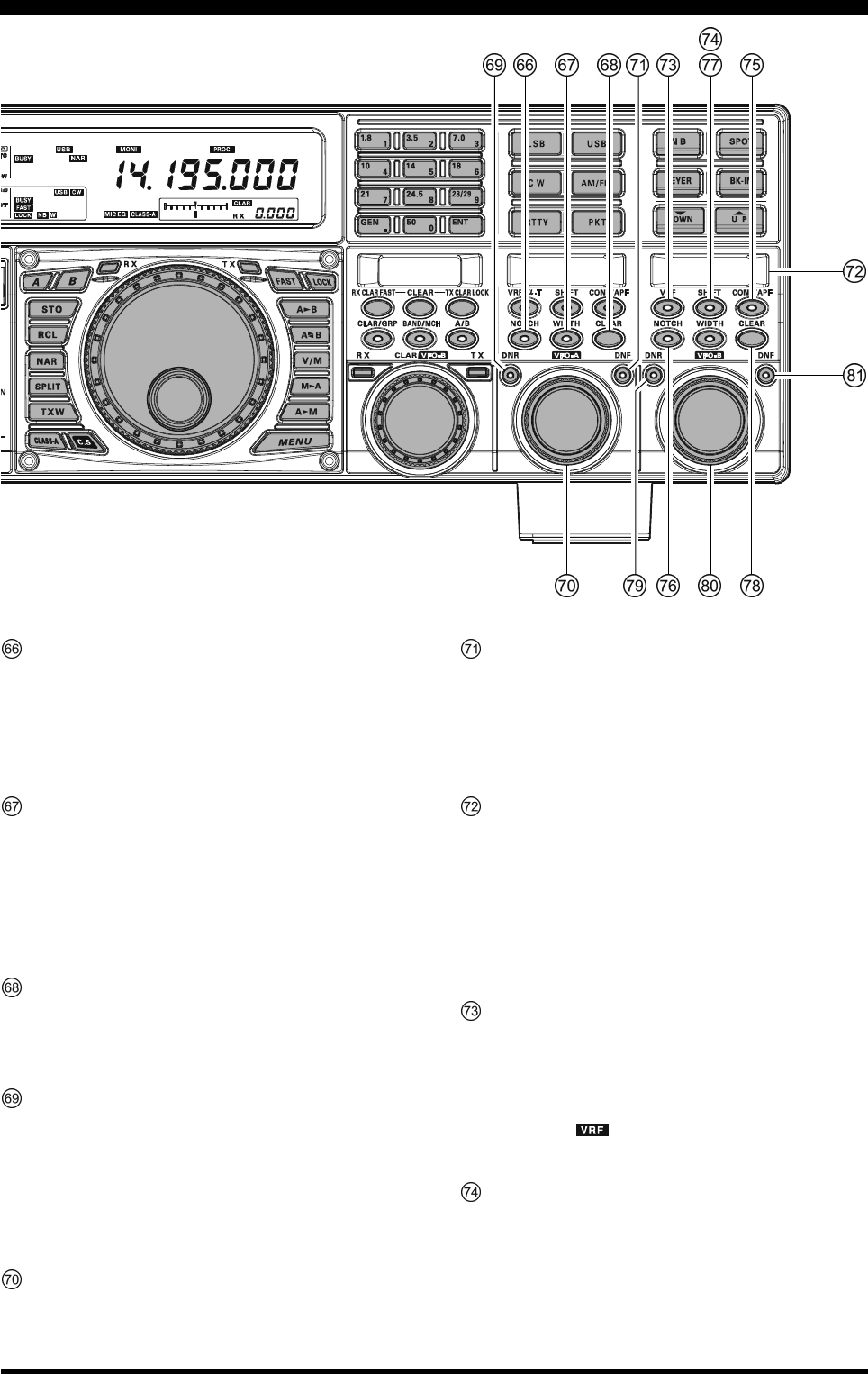
(VFO-A)[VRF/µ-T] Switch
This button turns the VFO-A receiver VRF filter “on”
and “off”, and allows you to adjust the center frequency
of the VRF filter with the (VFO-A)[SELECT] knob.
While activated, the red LED in this button will light
up, and the “ ” icon will appear in the FLT column
of the Block Diagram Display.
ADVICE:
When an optional RF µTuning Kit is connected, press-
ing this button will engage the µ-Tuning filter. The
µTuning Kit provides much better RF selectivity than
any other RF filter in the Amateur industry, yielding
outstanding protection from high RF levels not far re-
moved from the current operating frequency.
(VFO-A)[SHIFT] Switch
Pressing this button allows you to move the IF DSP
bandwidth of VFO-A “higher” or “lower” with the
(VFO-A)[SELECT] knob. When the IF passband is
shifted, the red LED imbedded in this button will light
up. To the contrary, when the IF passband is just cen-
tered, the red LED in this button turns off.
(VFO-A) [CONT/APF] Switch
In the SSB, AM, and FM modes, this button turns the
VFO-A receiver contour filter “on” and “off”, and al-
lows you to adjust the center frequency of the contour
filter with the (VFO-A)[SELECT] knob. When the
contour filter is activated, the red LED in this button
will light up.
In the CW mode, this button turns the VFO-A receiver
APF (Audio Peak Filter) “on” and “off”, and allows
you to adjust the bandwidth of the APF filter with the
(VFO-A)[SELECT] knob. When the APF filter is ac-
tivated, the red LED in this button will light up.
Page 28 FTDX5000 OPERATING MANUAL
(VFO-A)[NOTCH] Switch
This button turns the VFO-A receiver IF notch filter
“on” and “off”, and allows you to adjust the center fre-
quency of the notch filter with the (VFO-A)[SELECT]
knob. When the notch filter is activated, the red LED
in this button will light up.
(VFO-A)[WIDTH] Switch
Pressing this button allows you to adjust the overall
bandwidth of the VFO-A receiver IF DSP filter with
the (VFO-A)[SELECT] knob. When the bandwidth
is set to other than the factory default, the red LED in
this button will light up. When the bandwitdh is set to
default, the red LED in this button turns off.
(VFO-A)[CLEAR] Switch
Pressing this button will reset the function selected by
the five buttons located above and left of the button to
the factory default function.
(VFO-A)[DNR] Switch
This button toggles the VFO-A Receiver Digital Noise
Reduction circuit “on” and “off”, and allows you to
adjust the noise reduction level with the (VFO-
A)[SELECT] knob. When the Digital Noise Reduc-
tion is activated, the red LED in the button will light
up.
(VFO-A)[SELECT] Knob
This knob is used to adjust status of the functions se-
lected by the five buttons located above the knob.
(VFO-A)[DNF] Switch
This button toggles the VFO-A Receiver Digital Notch
Filter “on” and “off”. When the Digital Notch Filter is
activated, the red LED in the button will light up. This
is an automatic circuit, and there is no adjustment knob
for the DNF.
SUB DISPLAY-III
This OLED (Organic Light Emitting Diode) display
shows the characteristics of the VFO-B Receiver DSP
functions selected by the five buttons located below of
the display. Use the (VFO-B)[SELECT] knob located
below this window to adjust the function displayed in
the window. Alternately, when the Menu Mode is acti-
vated, this OLED displays the current menu selection.
(VFO-B)[VRF] Switch
This button turns the VFO-B Receiver VRF Filter “on”
and “off”, and permits adjustment of the VRF Filter
center frequency, using the (VFO-B)[SELECT] knob.
While activated, the orange LED in the button will light
up, and the “ ” icon will appear in the FLT column
of the Block Diagram Display.
(VFO-B)[SHIFT] Switch
Pressing this button allows you to move the IF DSP
bandwidth of VFO-B “higher” or “lower” with the
(VFO-B)[SELECT] knob. When the IF passband is
shifted, the orange LED in the button will light up.
Alternately, when the IF passband is centered, the LED
in the button turns off.
FRONT PANEL CONTROLS & SWITCHES

Page 29FTDX5000 OPERATING MANUAL
FRONT PANEL CONTROLS & SWITCHES
(VFO-B)[CONT/APF] Switch
In the SSB, AM, and FM modes, this button turns the
VFO-B Receiver Contour Filter “on” and “off”, and
enables adjustment of the Contour Filter center fre-
quency with the (VFO-B)[SELECT] knob. When the
Contour Filter is activated, the orange LED in the but-
ton will light up.
In the CW mode, this button turns the VFO-B Receiver
APF (Audio Peak Filter) “on” and “off”, and allows
you to adjust the bandwidth of the APF filter with the
(VFO-B)[SELECT] knob. When the APF filter is ac-
tivated, the orange LED in the button will light up.
(VFO-B)[NOTCH] Switch
This button turns the VFO-B Receiver IF notch filter
“on” and “off”, and enables adjustment of the notch
filter center frequency with the (VFO-B)[SELECT]
knob. When the notch filter is activated, the orange
LED in the button will light up.
(VFO-B)[WIDTH] Switch
Pressing this button allows you to adjust the overall
bandwidth of the VFO-B receiver IF DSP filter with
the (VFO-B)[SELECT] knob. When the bandwidth
is set to other than the factory default, the orange LED
in the button will light up. Alternately, when the band-
width is set to default, the orange LED in the button
turns off.
(VFO-B)[CLEAR] Switch
Pressing this button will reset the function selected by
the five buttons above and left of the button to factory
default.
(VFO-B)[DNR] Switch
This button toggles the VFO-B Receiver Digital Noise
Reduction circuit “on” and “off”, and allows you to
adjust the noise reduction level with the (VFO-
B)[SELECT] knob. When the Digital Noise Reduc-
tion is activated, the orange LED in the button will
light up.
(VFO-B)[SELECT] Knob
This knob is used to adjust status of the functions se-
lected by the five buttons located above the knob.
(VFO-A)[DNF] Switch
This button toggles the VFO-A Receiver Digital Notch
Filter “on” and “off”. When the Digital Notch Filter is
activated, the orange LED in the button will light up.
This is an automatic circuit, and there is no adjustment
knob for the DNF.
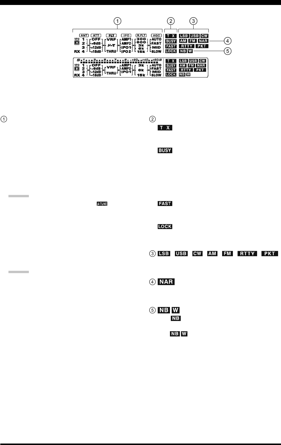
Page 30 FTDX5000 OPERATING MANUAL
(VFO-A) Block Diagram Display
ANT (1, 2, 3, 4, RX):
Indicates the antenna selected for operation by the front
panel [ANT 1-4] and [RX ANT] switches.
ATT (OFF, –6 dB, –12 dB, –18 dB):
Indicates the attenuation level selected for operation
by the front panel [ATT] button.
FLT (VRF, µ-TUNE, THRU):
Indicates the RF filter selected for operation by the
front panel (VFO-A)[VRF/µ-T] button.
ADVICE:
The µ-TUNE filter is an option. The “ ” icon will
not appear when the optional µ-TUNE unit is not con-
nected.
IPO (AMP1, AMP2, IPO1, IPO2):
Indicates the front end RF amplifier selected for op-
eration by the front panel [IPO] button.
R.FLT (300, 600, 3k, 6k, 15k):
Indicates the 1st IF Roofing Filter selected for opera-
tion with the front panel [R.FLT] button.
ADVICE:
The 300 Hz Roofing Filter is an option except the MP
version. The “300” icon will not appear when the op-
tional 300 Hz Roofing Filter is not installed.
AGC (AUTO, FAST, MID, SLOW):
Indicates the AGC decay time selected for operation
by the front panel [AGC] switch.
(VFO-A) Status Indicator
:
This indicator appears during transmission on the VFO-
A frequency.
:
This indicator appears whenever the VFO-A receiver
squelch is open. If this indicator is not showing, and
reception seems to have been lost on the VFO-A re-
ceiver for no apparent reason, check the position of
the (VFO-A)[SQL] knob, and rotate it fully counter-
clockwise to restore reception.
:
This indicator appears when the Main Tuning Dial tun-
ing rate is selected to fast.
:
This indicator appears when the Main Tuning Dial knob
is locked.
, , , , , ,
Displays the currently-selected operating mode for
VFO-A.
This indicator appears whenever the VFO-A receiver’s
narrow IF DSP filter is engaged.
The “ ” icon appears when the VFO-A receiver’s
(short duration) Noise Blanker is activated.
The “ ” icon appears when the VFO-A receiver’s
(longer-pulse) Noise Blanker is activated.
DISPLAY INDICATIONS (LEFT SIDE)
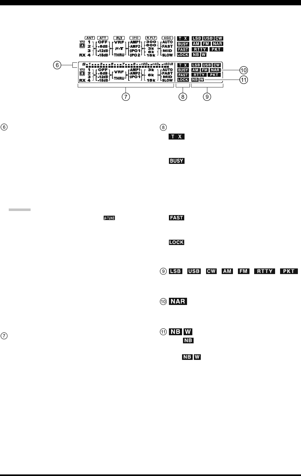
Page 31FTDX5000 OPERATING MANUAL
(VFO-B) Block Diagram Display
ANT (1, 2, 3, 4, RX):
Indicates the antenna selected for operation by the front
panel [ANT 1-4] and [RX ANT] switches.
ATT (OFF, –6 dB, –12 dB, –18 dB):
Indicates the attenuation level selected for operation
by the front panel [ATT] button.
FLT (VRF, THRU):
Indicates the RF filter selected for operation by the
front panel (VFO-A)[VRF] button.
ADVICE:
The µ-TUNE filter is an option. The “ ” icon will
not appear when the optional µ-TUNE unit is not con-
nected.
IPO (AMP1, AMP2, IPO1):
Indicates the front end RF amplifier selected for op-
eration by the front panel [IPO] button.
R.FLT (3k, 6k, 15k):
Indicates the 1st IF Roofing Filter selected for opera-
tion by the front panel [R.FLT] button.
AGC (AUTO, FAST, MID, SLOW):
Indicates the AGC decay time selected for operation
by the front panel [AGC] switch.
This indicator appears whenever the Digital Noise Re-
duction feature is activated.
(VFO-B) Receiver S-Meter
Displays the strength of signals received on VFO-B.
(VFO-B) Status Indicator
:
This indicator appears during transmission on the VFO-
B frequency.
:
This indicator appears whenever the VFO-B receiver
squelch is open. If this indicator is not showing, and
reception seems to have been lost on the VFO-B re-
ceiver for no apparent reason, check the position of
the (VFO-B)[SQL] knob and rotate it fully counter-
clockwise to restore reception.
:
This indicator appears when the [CLAR(VFO-B)]
knob’s tuning rate is selected to fast.
:
This indicator appears when the [CLAR(VFO-B)]
knob is locked.
, , , , , ,
Displays the currently-selected operating mode for
VFO-B.
This indicator appears whenever the VFO-B receiver’s
narrow IF DSP filter is engaged.
The “ ” icon appears when the VFO-B receiver’s
(short duration) Noise Blanker is activated.
The “ ” icon appears when the VFO-B receiver’s
(longer-pulse) Noise Blanker is activated.
DISPLAY INDICATIONS (LEFT SIDE)
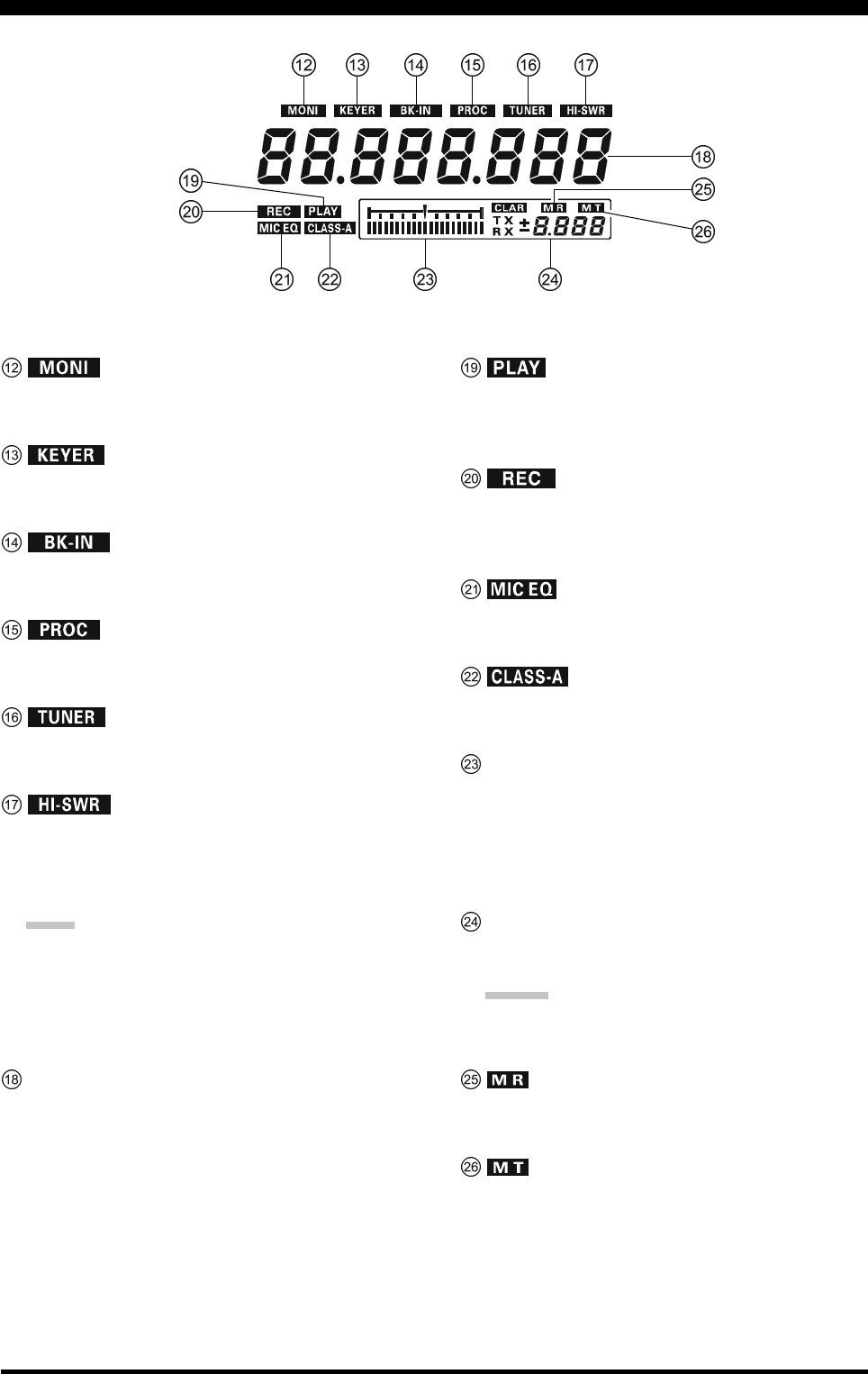
Page 32 FTDX5000 OPERATING MANUAL
This indicator appears when the transmit monitor cir-
cuit is activated.
This indicator appears when the internal CW keyer is
activated.
This indicator appears when CW break-in operation is
activated.
This indicator appears when the DSP Speech Proces-
sor is activated.
This indicator appears when the internal Automatic An-
tenna Tuner is activated.
This indicator appears if the directional coupler and
microprocessor detect an abnormally high SWR con-
dition (over 3.0:1) that cannot be resolved by the Au-
tomatic Antenna Tuner.
NOTE:
If this indicator appears, check to be sure that you have
the correct antenna selected on the current operating
band. If so, you will need to check the condition of the
antenna, its coaxial cable, and/or the connectors on the
cable, to locate and correct the fault.
VFO-A Frequency Display
This is the VFO-A frequency display.
This indicator appears while the voice recorder is play-
ing back the recorded audio, and/or the memory is play-
ing back the recorded CW or voice message.
This indicator appears while the voice recorder is re-
cording the receiver audio, and/or the memory is re-
cording your CW or voice message.
This indicator appears when the Three-Band Paramet-
ric Microphone Equalizer is activated via the Menu.
This indicator appears when Class-A operation is en-
gaged.
Tuning Offset Indicator
This is a tuning scale that, as configured from the fac-
tory, provides a visual CW tuning indication of the in-
coming signal’s offset from your transceiver’s CW car-
rier frequency, as programmed by the relative clarifier
offset, or the peak position of the VRF/µ-TUNE filter.
CLAR
This indicator appears when the Clarifier function is
activated.
ADVIDE:
When adjusting some knobs, the current value will
appear in this area.
This indicator appears when the transceiver is in the
Memory Recall mode.
This indicator appears when the transceiver is in the
Memory Tune mode to indicate that the memory con-
tents have been temporarily changed.
DISPLAY INDICATIONS (RIGHT SIDE)
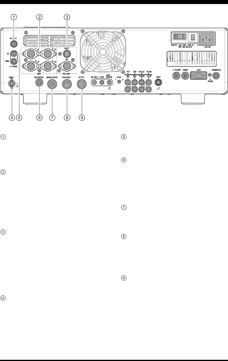
Page 33FTDX5000 OPERATING MANUAL
REAR PANEL CONNECTIONS
IF OUT Jacks
This RCA jack outputs the 9 MHz IF signal of the re-
ceived signal when Menu item “109 RGEN IF OUT”
is set to “ENABLED”. This signal does not pass through
the roofing filter.
ANT 1, 2, 3, 4 Jacks
Connect your main antenna(s) here, using a type-M
(PL-259) plug and coaxial feedline for each. These an-
tenna ports are always used for transmission. They are
also used for reception, unless a separate receive an-
tenna is connected to the RX ANT IN jack and used
for the receiver. The internal antenna tuner affects only
the antenna(s) connected here, and only during trans-
mission.
RX ANT IN Jack
The BNC jack provides output of the receiver signal
from the Antenna jacks, which are connected to the
“RX” side of the transceiver T/R switching circuitry.
The type-M jack is for a separate, receive-only antenna.
An antenna connected here can be used when the [RX
ANT] button on the front panel is pressed.
If you want to use some special kind of external
bandpass filter or preamplifier, you may connect it
between the “RX ANT OUT” and “RX ANT IN” jacks.
GND
Use this terminal to connect the transceiver to a good
earth ground, for safety and optimum performance. Use
a large diameter, short braided cable for making ground
connections. Please refer to page 9 for other notes about
proper grounding.
µ-TUNE Jacks
These jacks are used for signal input/output of the op-
tional RF µTuning Kits.
ROTATOR Jack
This 6-pin MINI-DIN Jack accepts a cable connected
to a YAESU G-800DXA/-1000DXA/-2800DXA An-
tenna Rotator (listed models are current as of early
2010). You may control the antenna azimuth rotation
(and rotation speed) using the Function buttons on the
front panel.
BAND DATA Jack
This 8-pin output jack provides band selection data
which may be used for control of optional accessories
such as the VL-1000 Solid-state Linear Amplifier.
PACKET Jack
This 5-pin input/output jack provides receiver audio
and squelch signals, and accepts transmit (AFSK) au-
dio and PTT control, from an external Packet TNC.
Pinout is shown on page 15. The receiver audio level
at this jack is approximately 100 mVp-p (@600 Ohms).
RTTY Jack
This 4-pin input/output jack provides connections for
an RTTY terminal unit. Pinout is shown on page 15.
The receiver audio level at this jack is at a constant
100-mV (@600 Ohms) level. FSK keying at this jack
is accomplished by a closure of the SHIFT line to
ground by the terminal unit.
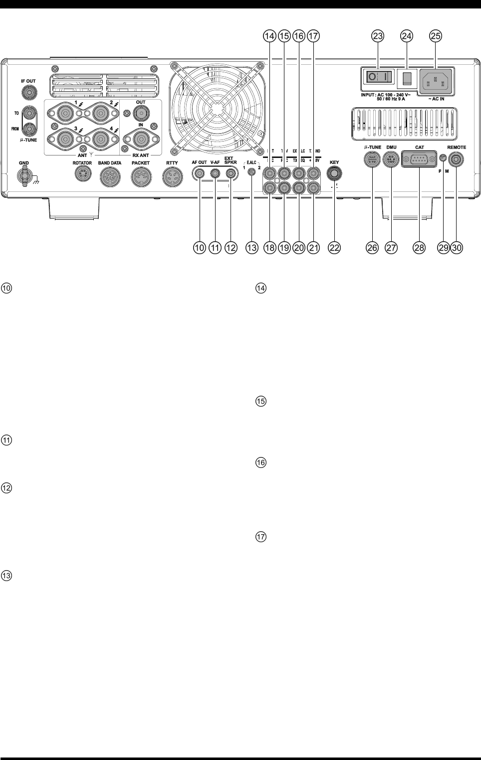
Page 34 FTDX5000 OPERATING MANUAL
AF OUT Jack
This 3.5-mm, 3-contact jack provides dual-channel
low-level receiver output, for recording or external am-
plification. Peak signal level is 300 mVp-p at 10 k-
Ohms. The VFO-A receiver audio is on the left chan-
nel (tip), and the VFO-B receiver audio is on the right
channel (ring). A stereo amplifier or recorder is rec-
ommended, to record each receiver’s audio separately
when dual reception is enabled (audio from either re-
ceiver, or both, may be used). The front panel [AF
GAIN] knobs do not affect the signals at this jack.
V-AF Jack
This 3.5-mm, 3-contact jack is used for connection to
the optional SM-5000 Station Monitor.
EXT SPKR Jack
This 3.5-mm, 2-contact jack provides receiving audio
output from the VFO-A and VFO-B receivers for an
external loudspeaker or speakers, such as the SP-2000.
Inserting a plug into the jack disables the internal loud-
speaker. Impedance is 4 ~ 8 Ohms.
E.ALC Switch
This slide switch is used to select the recovery time of
the ALC. Set this switch to the “1” position when the
transceiver is connected to the optional VL-1000 Solid-
state Linear Amplifier.
PTTJack
This RCA input jack may be used to provide manual
transmitter activation using a footswitch or other
switching device. Its function is identical to the [MOX]
button on the front panel. The same line is available at
the PACKET and RTTY jacks for TNC control. Open
circuit voltage is +13.5 VDC, and closed-circuit cur-
rent is 5 mA.
TRV Jack
This RCA jack provides a low level RF output for use
with a transverter. Maximum output is approximately
–10 dBm (0.1 mW) at 50 Ohms.
EXT ALC Jack
This RCA input jack accepts negative-going external
ALC (Automatic Level Control) voltage from a linear
amplifier, to prevent over-excitation by the transceiver.
Acceptable input voltage range is 0 to –4 VDC.
TX GND Jack
This RCA jack is closed to ground while the transmit-
ter is engaged. It may be used for control of a periph-
eral device, most typically a linear amplifier. To en-
able the jack, set Menu item “172 TGEN ETX-GND”
to the “ENABLE”.
The relay circuit used for this jack is capable of switch-
ing an AC voltage of 100 Volts at up to 300 mA, or a
DC voltage of 60 V at 200 mA, or DC 30 V at up to 1
Amp.
REAR PANEL CONNECTIONS
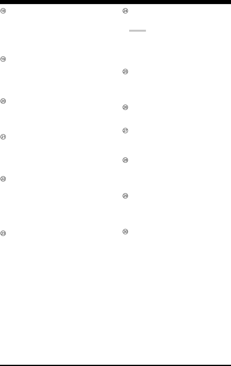
Page 35FTDX5000 OPERATING MANUAL
REAR PANEL CONNECTIONS
MIC (PATCH) Jack
This RCA input jack accepts either AFSK or voice
audio, for transmission. This line is mixed with the mi-
crophone audio input line, so the microphone should
be disconnected if using this jack and mixing is not
desired. The optimum impedance is 500 ~ 600 Ohms,
and the nominal input level should be 5 mV.
REC Jack
This RCA jack provides low-level receiver audio out-
put and transmit (monitor) audio (requires the [MONI]
button is turned on), for external recording or external
amplification. Peak signal level is 30 mVp-p at 10 k-
Ohms.
TX REQ Jack
When this RCA jack is shorted to ground, it puts the
transceiver into the transmit mode, and sends out a
steady CW carrier, for linear amplifier or manual an-
tenna tuner adjustment.
+13.8 V Jack
This RCA output jack provides regulated, separately
fused 13.8 VDC at up to 200 mA, to power an external
device such as a packet TNC. Make sure your device
does not require more current (if it does, use a separate
power source).
KEY Jack
This 1/4-inch phone jack accepts a CW key or keyer
paddle. A 2-contact plug cannot be used in this jack.
Key-up voltage is +5 V, and key-down current is 1 mA.
Plug wiring is shown on page 15, and the jack may be
configured for keyer, “Bug,” “straight key,” or com-
puter keying interface operation via Menu item “059
A1A R-TYPE.”
Main Power Switch
This is the main power “on” (I)/“off” (O) switch of the
transceiver. Always turn this switch on before turning
on the front panel [POWER] button.
If this switch is not turned “on”, the front panel
[POWER] switch will not function.
Circuit Breaker Switch
This circuit breaker shuts off in the event of danger-
ously high current consumption by the transceiver.
ADVICE:
If the Circuit Breaker interrupts power, by all means
try to determine the cause of the over-current condi-
tion before re-applying power. To restore the Circuit
Breaker after verifying that all is normal, push the
switch in until you hear a “click”.
~AC IN Jack
Connect the supplied 3-wire AC line cord to this socket.
AC voltages of 100-240 V may be accommodated by
the transceiver without any sort of modification (uni-
versal voltage input).
µ-TUNE Jack
This 10-pin MINI-DIN jack is used for control of the
optional RF µTuning Kits.
DMU Jack
This 8-pin MINI-DIN jack accepts a cable connected
to an optional DMU-2000 Data Management Unit or
SM-5000 Station Monitor.
CAT Jack
This 9-pin serial DB-9 jack allows external computer
control of the transceiver. Connect a serial cable here
and to the RS-232C COM port on your personal com-
puter (no external interface is required).
PGM (PROGRAM) Switch
This slide switch is used for updating the transceiver’s
firmware. The update software and instructions are
available for download from the Vertex Standard
website (http://www.yaesu.com/).
REMOTE Jack
By plugging the supplied FH-2 Remote Control Key-
pad into this jack, direct access to the CPU is provided,
for control of functions such as the audio playback fea-
ture, and the contest memory keyer, plus frequency and
function control.
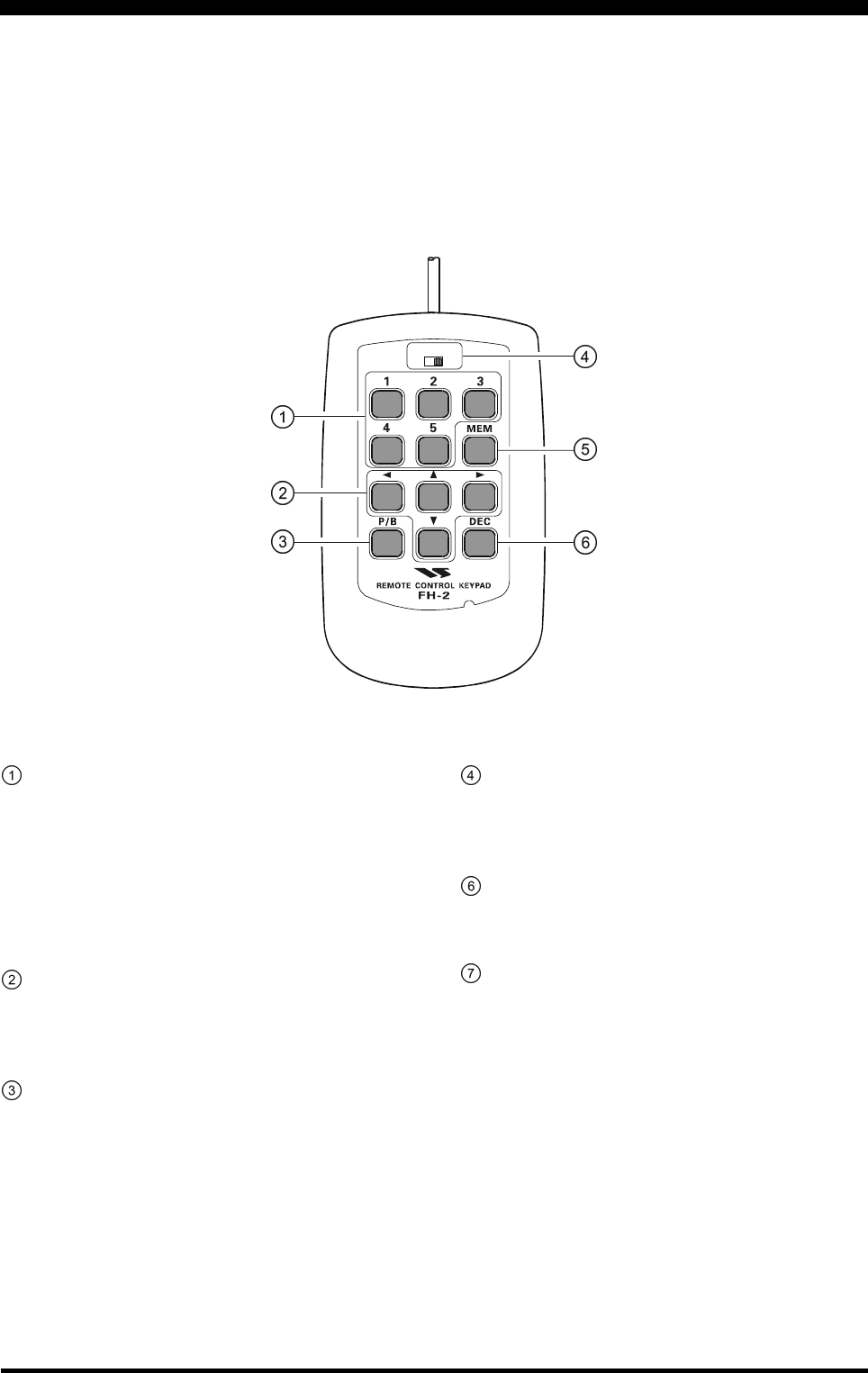
Page 36 FTDX5000 OPERATING MANUAL
FH-2 SWITCHES
The supplied Remote Control Keypad “FH-2” can be used to control the voice memory capability for the SSB/AM/FM
modes, and the contest memory keyer for the CW mode. You can also play-back up to 15 seconds of incoming received
audio, for verification of a missed callsign or other purposes. Some specific capabilities of the FH-2 are:
On SSB/AM/FM modes, five channels of storage and playback of voice memory (20 seconds each), using your own
voice for recording (see page 80).
On CW mode, the FH-2 provides storage and recall of CW messages for repetitive CQ and contest number transmis-
sions (see pages 94 and 96).
Play-back of the last 15 seconds of incoming receiver audio (see page 45).
[1], [2], [3], [4], [5] Switches
These buttons work as the Voice Memory and CW Mes-
sage Memory Selection Key.
In the case of Voice Memory, up to 20 seconds of au-
dio may be stored on each channel.
For CW Messages and CW Text Messages, up to 50
characters (“PARIS” specification) may be stored into
each channel.
[], [], [], [] Switches
These buttons are used for navigation when selecting
text characters for the programming of Contest and Text
memories.
[P/B] Switch
This button is used for playing back the last 15 sec-
onds of recorded receiver audio.
LOCK
OFFON
[LOCK] Switch
This button may be used to lock out the FH-2 key but-
tons, to prevent accidental activation of FH-2 opera-
tions.
[MEM] Switch
Press this button to store either a Voice Memory, or a
Contest Keyer Memory.
[DEC] Switch
When utilizing the sequential contest number capabil-
ity of the Contest Keyer, press this button to decre-
ment (decrease) the current Contest Number by one
digit (i.e. to back up from #198 to #197, etc.).

Page 37FTDX5000 OPERATING MANUAL
Before turning on main power, please verify the following precautions once more.
Verify all ground connections are secure. See page 9 for details.
Connect the antenna(s) to the rear-panel Antenna jack(s). See page 10 for details.
Connect the microphone (and/or key or paddle). See pages 11 and 12 for details.
If using a linear amplifier, verify the interconnections have been successfully completed? See pages 13 and 14 for
details.
Rotate both [AF GAIN] controls to their fully counter-clockwise positions, to avoid a loud blast of audio when the
transceiver turns on. See page 21 for details.
Rotate the [RF PWR] control fully counter-clockwise, to set minimum power to begin. See page 20 for details.
If your AC mains power should suffer a significant fluctuation or interruption, we recommend that you go through a
complete power-up cycle, in order to ensure that all circuits are properly initialized. To do this, be sure the front panel
[POWER] switch is turned off, then set the rear panel main power switch to the “O” position. Now unplug the AC
cable from the rear panel, and wait ten seconds before continuing with the start-up procedure described on the next
page.
BASIC OPERATION:RECEIVING ON AMATEUR BANDS
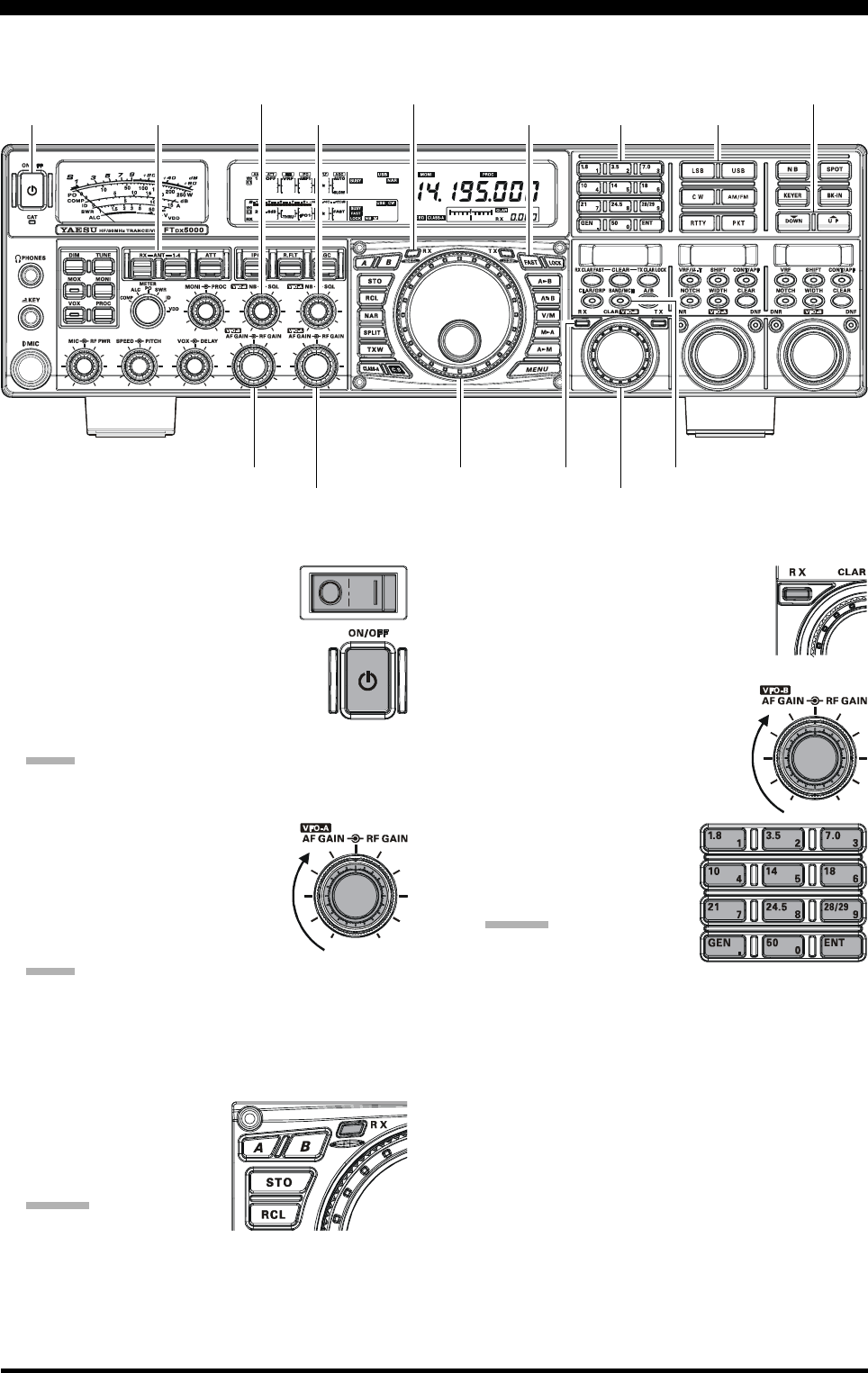
Page 38 FTDX5000 OPERATING MANUAL
Main Tuning Dial knob
[ANTENNA] Buttons [BAND] Buttons
(VFO-B)[SQL] Knob
[BAND/MHz] Button
[FAST] Button
[CLAR(VFO-B)] Knob
1. Plug the AC cable back in, set the rear
panel main power switch to the “I”
position.
2. Press and hold in the front panel
[POWER] switch for one second to turn
the transceiver on.
3. The transceiver will start up on 7.000.00
MHz LSB, and normal operation may begin.
NOTE:
To turn power off, press and hold in the front panel
[POWER] switch for one second.
4. Rotate the (VFO-A)[AF GAIN]
knob to set a comfortable audio level
on incoming signals or noise. Clock-
wise rotation of the (VFO-A)[AF
GAIN] knob increases the volume
level.
NOTE:
When using headphones, start by rotating the (VFO-
A)[AF GAIN] knob counter-clockwise, then bring the
volume level up after you put the headphones on. This
will minimize the chance of damage to your hearing
caused by an unexpectedly-high audio level.
5. Press the (VFO-A)[RX]
button to engage the VFO-
A receiver; the imbedded
LED will glow green.
ADVICE:
If you press the (VFO-
A)[RX] button when the LED is already glowing
green, the LED will begin blinking; this indicates
that the VFO-A receiver is temporarily muted. Press
the (VFO-A) [RX] button once more to restore
VFO-A receiver operation.
Press the (VFO-B)[RX] button to
engage Dual Reception (using the
VFO-B receiver in addition to the
VFO-A receiver). When you press
the (VFO-B)[RX] button, it will
glow green; pressing the button
once more will turn the VFO-B
receiver off, and the LED will go
dark. Use the (VFO-B)[AF
GAIN] knob to adjust the VFO-
B receiver volume level.
6. Press the [BAND] button
corresponding to the Ama-
teur band you wish to oper-
ate on.
ADVICE:
One-touch selection of
each Amateur band be-
tween 1.8 and 50 MHz is provided.
The FTDX5000 utilizes a triple band-stack VFO
selection technique. This permits you to store up to
three favorite frequencies and modes for each band
in the VFO registers. For example, you may store
one frequency for 14 MHz CW, one for RTTY, and
one for USB, then recall each VFO by successive,
momentary presses of the [14] MHz band button.
Each Amateur band button has three frequency/
mode settings associated with it.
[POWER] Switch
(VFO-A)[RX] Button
BASIC OPERATION:RECEIVING ON AMATEUR BANDS
Here is the typical start-up procedure for normal operation:
(VFO-A)[SQL] Knob [MODE] Buttons
(VFO-B)[AF GAIN] Knob
(VFO-A)[AF GAIN] Knob
[()DOWN] /[()UP] Buttons
(VFO-B)[RX] Button
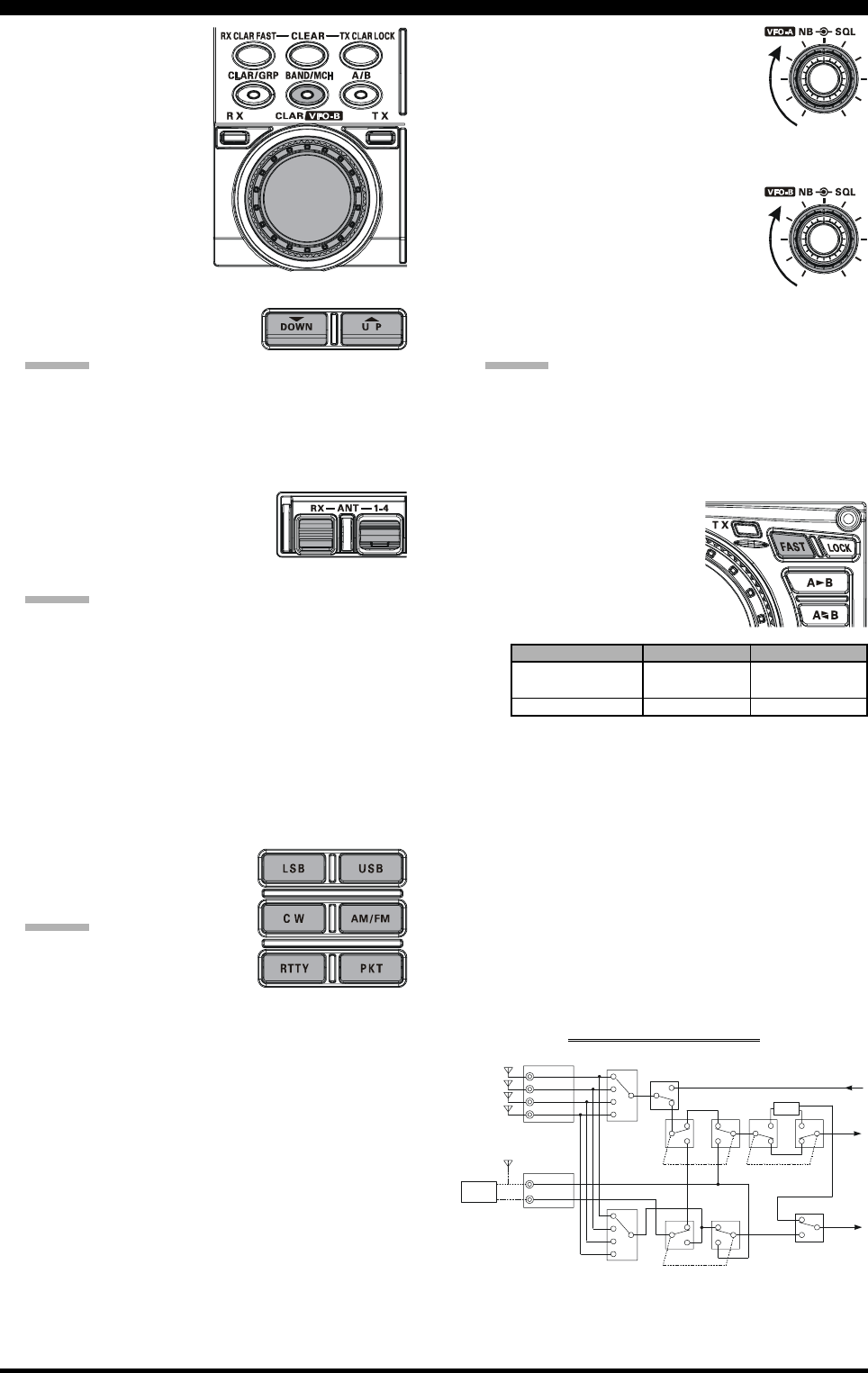
Page 39FTDX5000 OPERATING MANUAL
If you press the
[BAND/MCH] but-
ton briefly, the button
glows red, and the
[CLAR(VFO-B)]
knob may be used as
the band selection
knob.
7. Press the [(DOWN)]/[(UP)] buttons to tune the
VFO-A frequency in 1 MHz
steps.
ADVICE:
You may change the tuning step to 100 kHz via Menu
item “144 TUN MHz SEL”. See page 133.
8. Move the [ANT 1-4] button up or down to select the
appropriate antenna for the band in use. Alternatively,
you may also press the [RX ANT] button to select the
receive antenna, if one is con-
nected. Up to four TX/RX anten-
nas and one RX-only antenna may
be connected.
ADVICE:
Your antenna selection is “remembered” (in con-
junction with the frequency and mode) in the VFO
register in use, when you choose that particular
antenna.
When VFO-A and VFO-B are switched to the same
antenna jack, VFO-B receiver will be automatically
connected to the RX ANT jack.
When both VFO-A and VFO-B are switched to the
RX ANT, the signal output from the RX OUT jack
is connected to the VFO-A receiver.
9. Press the appropriate [MODE]
button to select the desired op-
erating mode.
ADVICE:
By convention in the Ama-
teur bands, LSB is used on
the 7 MHz and lower bands
(with the exception of 60 meters), while USB is
utilized on the 14 MHz and higher bands.
When changing modes from SSB to CW, you will
observe a frequency shift on the display. This shift
represents the BFO offset between the “zero beat”
frequency and the audible CW pitch (tone) you can
hear (the pitch is programmed by the [PITCH]
knob), even though the actual tone that you hear is
not changing. If you do not want this frequency shift
to appear when changing modes, you may change
the BFO offset setting in Menu item “066 A1A FRQ
DISP”, described on page 127.
When operating on the FM mode
in the VFO-A, rotate the (VFO-
A)[SQL] (Squelch) knob clock-
wise just to the point where the
background noise is silenced. This
is the point of maximum sensitivity to weak sig-
nals. Excessive advancement of the
Squelch knob will degrade the abil-
ity of the receiver to detect weak
signals. Adjustment of the VFO-B
Squelch is accomplished using the
(VFO-B)[SQL] knob.
10.
Rotate the Main Tuning Dial knob to tune around the
band, and begin normal operation.
ADVICE:
Clockwise rotation of the Main Tuning Dial knob
increases the operating frequency, one “step” of the
synthesizer at a time; similarly, counter-clockwise
rotation of the Main Tuning Dial knob will decrease
the frequency.
A “normal” and a “fast”
step choice is available on
each operating mode.
Pressing the [FAST] but-
ton engages the “Fast”
tuning selection.
BASIC OPERATION:RECEIVING ON AMATEUR BANDS
OPERATING MODE 1 STEP 1 DIAL ROTATION
LSB, USB, CW, 10Hz 10kHz
RTTY, PKT(LSB)[
100Hz][
100kHz]
AM, FM, PKT(FM)100Hz [1kHz]100kHz [1MHz]
[ ] : [FAST] switch set to “ON”
It is possible to set the frequency dial rotation steps
separately, solely for CW mode operation, using
Menu items “142 TUN DIAL STP”, and “143 TUN
CW FINE”. See page 133.
If you want to navigate frequency change quickly,
there are several techniques available:
Direct keyboard entry of the frequency (see page
49).
Use of the microphone [UP]/[DWN] scanning
keys, if your microphone is so equipped (see
page 49).
ANTENNA SWITCH
(VFO-A)
ANTENNA SWITCH
(VFO-B)RX ANTENNA SWITCH
(VFO-B)
RX ANTENNA SWITCH
(VFO-A)
TX/RX RELAY Transmitter
Section
VFO-A
Receiver
VFO-B
Receiver
BPF
ANT “1”
ANT “3”
ANT “2”
ANT “4”
RX ANT
RX OUT
Divider
SEPARATE
SEPARATE
ANTENNA CIRCUIT DIAGRAM
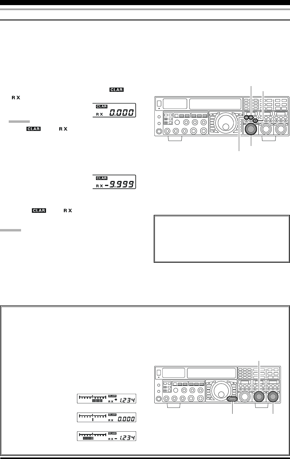
Page 40 FTDX5000 OPERATING MANUAL
BASIC OPERATION:RECEIVING ON AMATEUR BANDS
CLAR (CLARIFIER) OPERATION ON VFO-A
The [RX CLAR/FAST], [CLEAR], [TX CLAR/LOCK] buttons, and the [CLAR(VFO-B)] knob are used to offset the
receive, the transmit, or both frequencies from their settings on VFO-A (the Clarifier does not affect VFO-B). The four
small numbers on the LCD display show the current Clarifier offset. The Clarifier controls on the FTDX5000 are designed
to allow you to preset an offset up to ±9.999 kHz without actually retuning, and then activate it usning the Clarifier [RX
CLAR/FAST] and [TX CLAR/LOCK] buttons. This feature is ideal for following a drifting station, or for setting the small
frequency offsets sometimes utilized in DX “Split” operation.
Here is the technique for utilizing the Clarifier:
1. Press the [RX CLAR/FAST] button. The “ ” and
“” icons will appear in the display, and the pro-
grammed offset will be applied to
the receive frequency.
ADVICE:
If the “ ” and “ ” icons do not appear, check
to see if the [A/B] button glows orange. If so, press the
[A/B] button to cause the LED in the [A/B] button to
go out. Now, press the [RX CLAR/FAST] button to
begin clarifier operation.
2. Rotation of the [CLAR(VFO-B)] knob will allow you
to modify the initial offset on the
fly. Offsets of up to ±9.999 kHz
may be set using the Clarifier.
To cancel Clarifier operation, press the [RX CLAR/FAST]
button. The “ ” and “ ” icons will disappear from
the display.
ADVICE:
Turning the clarifier “off” simply cancels the application
of the programmed offset from the receive and/or transmit
frequencies. To clear out the programmed clarifier offset
altogether, and reset it to “zero,” press the [CLEAR] but-
ton.
TX CLAR
Without changing the receive frequency, you may
alternatively apply the Clarifier offset to the trans-
mit frequency (typically, for “split” DX pile-ups).
See page 82 for details.
The Tuning Offset Indicator provides a graphical representation of the Clarifier offset.
In CW mode, the Tuning Offset Indicator is depicts the CW Center Tuning, instead of the Clarifier Offset, this is the
factory default setting. If you wish to change this, so that the Clarifier Offset is also displayed on CW, use the
following procedure:
1. Press the [MENU] button to enter the Menu mode.
2. Rotate the (VFO-A)[SELECT] knob to select
Menu item “012 DISP BAR SEL”.
3. Rotate the (VFO-B)[SELECT] knob to select
“CLAR (Clarifier)” (replacing the default “CW
TUNE (CW TUNING)”
selection).
4. Press and hold in the
[MENU] button for two
seconds to save the new
setting and exit to nor-
mal operation.
[CLAR(VFO-B)] Knob
[RX CLAR/FAST] Button
[CLEAR] Button
[A/B] Button
[Plus (+) Offset]
[Zero Offset]
(Minus (–) Offset)
(VFO-B)[SELECT] Knob
[MENU] Button
(VFO-A)[SELECT] Knob
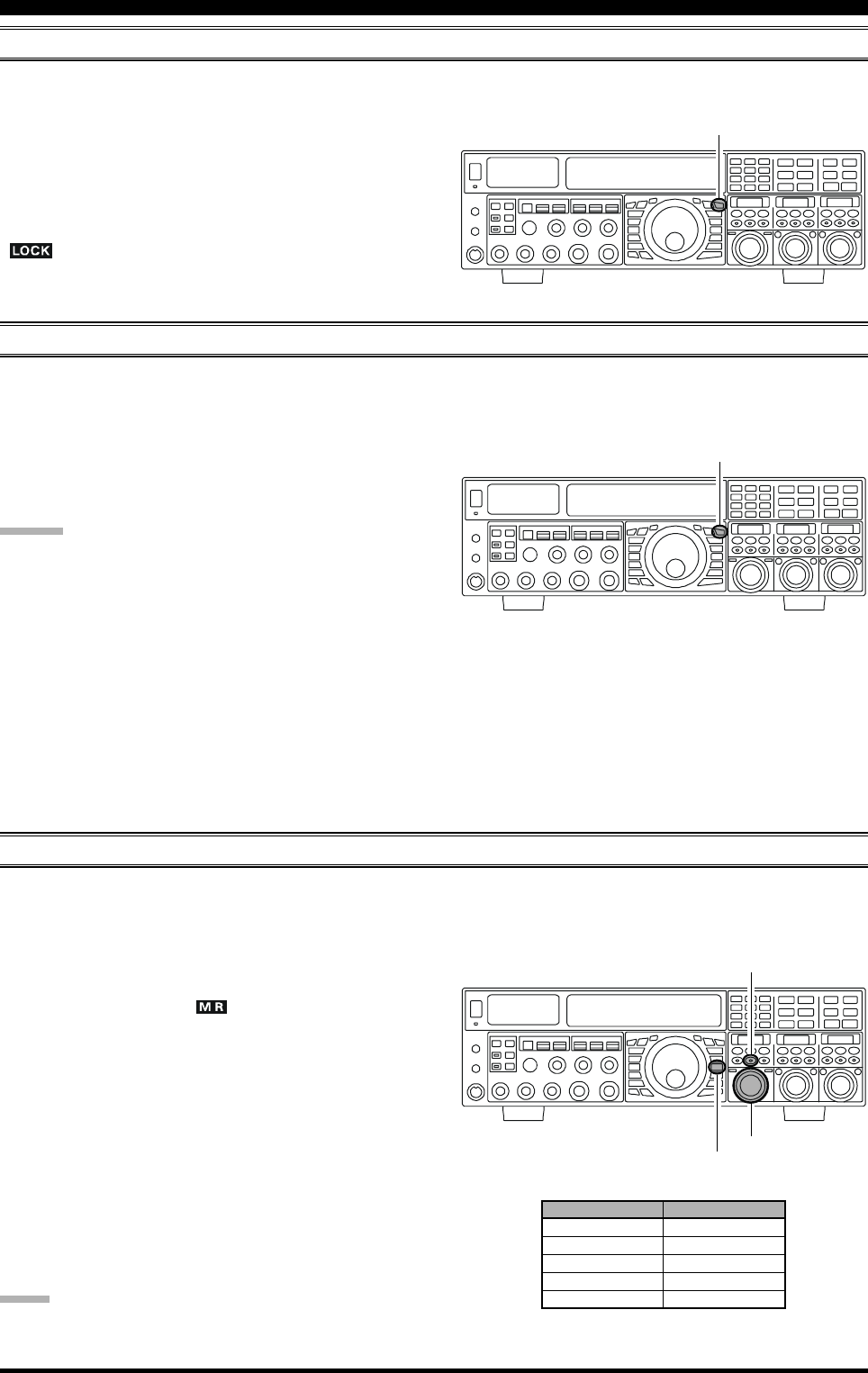
Page 41FTDX5000 OPERATING MANUAL
LOCK
You may lock the setting of the Main Tuning Dial knob, to prevent accidental frequency change.
To lock out the Main Tuning Dial knob, just press the
[LOCK] button that is located to the right of the Main
Tuning Dial knob. To unlock the Dial setting, and restore
normal tuning, just press the [LOCK] button once more.
When the Main Tuning Dial knob is “locked”, the blue
“” icon will appear on the display.
DIM
The illumination level of the analog meter and frequency display may be reduced, if you are using the transceiver in a dark
environment where high brightness is not desired.
To reduce the illumination level, press the [DIM] button,
located to the left of the analog meter. To restore full bright-
ness, press the [DIM] button once more.
ADVICE:
The amount of brightness may be customized for different
front panel areas. The follwing menu settings are effective
when the [DIM] button is depresses:
008 DISP DIM MTR: for analog meter
009 DISP DIM VFD: for frequency dispaly
010 DISP DIM OLE:SUB DISPLAY windows
011 DISP DIM ELCD: for Spectrum Scope display
of the optional SM-5000 Sta-
tion Monitor
[LOCK] Button
[LOCK] Button
OPERATION ON 60-METER (5 MHZ) BAND (U.S. VERSION ONLY)
The recently-released 60-meter band is covered, in the FTDX5000, by five special, fixed memory channels. These channels are
set to USB, and they appear between the “last” PMS channel (“P-9U”) and the first “regular” memory channel (Channel 1).
To operate on the 60-meter (5 MHz) band:
1. Press the [V/M] button once, if neccessary, to enter the
“Memory” mode (the “ ” icon will appear on the
display.
2. Press and hold in the [BAND/MCH] button for two
seconds. The button will glow yellow to signify that
rotation of the [CLAR(VFO-B)] knob will allow se-
lection of the memory channel.
3. Memory channels “US-1” through “US-5” are pre-pro-
grammed, at the factory, with the permitted frequen-
cies in the 5 MHz band, and the USB mode is auto-
matically selected on these channels.
4. To exit from 60-meter operation and return to the VFO
mode, just press the [V/M] button.
NOTE:
The frequencies and operating mode for 5 MHz band op-
eration are both fixed, and may not be changed.
[CLAR(VFO-B)] Knob
[V/M] Button
[BAND/MCH] Button
CHANNEL NUMBER
US-1
US-2
US-3
US-4
US-5
FREQUENCY
5.3320 MHz
5,3480 MHz
5.3680 MHz
5.3730 MHz
5.4050 MHz
BASIC OPERATION:RECEIVING ON AMATEUR BANDS
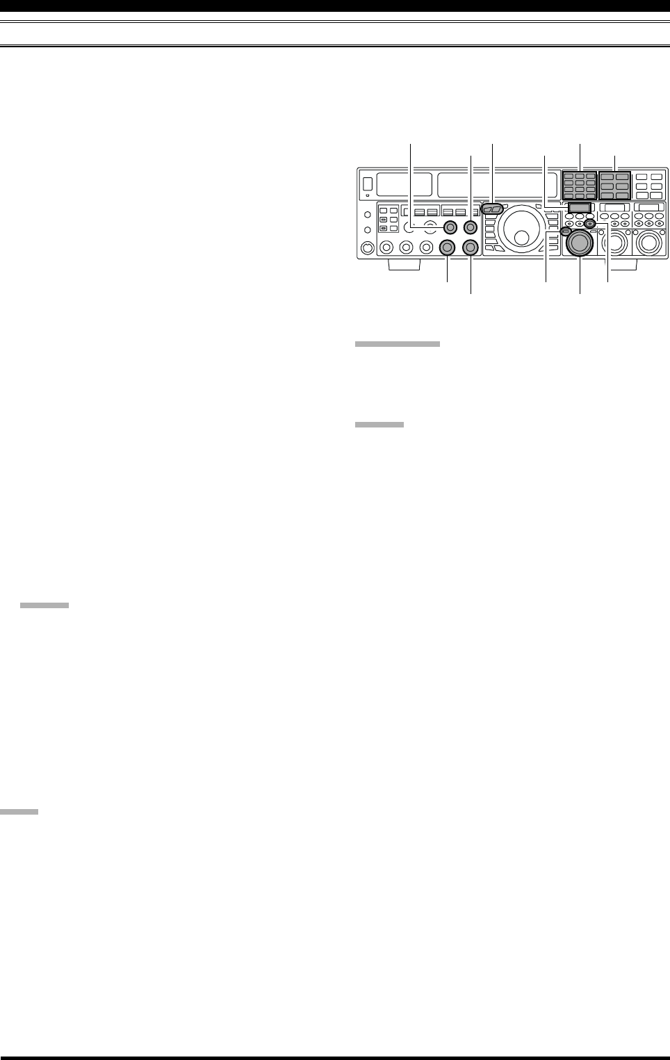
Page 42 FTDX5000 OPERATING MANUAL
QUICK POINT:
By convention in the amateur bands, LSB is used on the 7
MHz and lower bands (with the exception of 60 meters),
while USB is utilized on the 14 MHz and higher bands.
ADVICE:
When operating in Dual Receive, the manner in which
the audio is fed to the left and right headphones (Ste-
reo, Monaural, or Mixed) may be configured using
Menu item “108 ROUT HEADPHN” (see page 130).
When changing modes from SSB to CW, you will ob-
serve a frequency shift on the display. This shift repre-
sents the BFO offset between the “zero beat” frequency
and the audible CW pitch (tone) you can hear (the pitch
is programmed by the [PITCH] knob), even though
the actual tone that you hear is not changing. If you do
not want this frequency shift to appear when changing
modes, you may change the BFO offset setting in Menu
item “066 A1A FRQ DISP”, described on page 127.
When operating on the FM mode on the VFO-B re-
ceiver, rotate the (VFO-B)[SQL] knob clockwise just
to the point where the background noise is silenced.
This is the point of maximum sensitivity to weak sig-
nals. Excessive advancement of the (VFO-B)[SQL]
knob will degrade the ability of the receiver to detect
weak signals. Adjustment of the VFO-A squelch is ac-
complished using the (VFO-A)[SQL] knob.
DUAL RECEIVE
The FTDX5000 is capable of simultaneous reception on the same amateur band, using the VFO-A and VFO-B receivers,
in the “Dual Receive” mode. This is especially useful for DX work, here is the operating procedure for Dual Receive
operation.
CONVENIENCE FEATURES
1. While receiving on VFO-A, engage the VFO-B receiver
by pressing the (VFO-B)[RX] button, located to the
upper left of the [CLAR(VFO-B)] knob. You will now
be receiving on the two frequencies shown on the LCD
display (for VFO-A) and SUB DISPLAY-
I
(for VFO-
B).
2. Adjusting the volume:
To adjust the VFO-A audio level, rotate the (VFO-
A)[AF GAIN] knob. To adjust the VFO-B audio level,
rotate the (VFO-B)[AF GAIN] knob. In both cases,
clockwise rotation of the knob will increase the vol-
ume level.
3. Press the [B] button, located to the upper left of the
Main Tuning Dial knob. The [B] button will glow or-
ange, and you may now change the operating mode of
the VFO-B receiver by pressing the appropriate
[MODE] selection button.
4. You may also press the [BAND] buttons to select the
operating band for the VFO-B receiver.
5. To return the mode and band selections to VFO-A, press
the [A] button, located to the left of the [B] button.
The [A] button will glow red, and you may now change
the operating mode and band of the VFO-A receiver.
6. Rotate the Main Tuning Dial knob to adjust the Main
VFO-A frequency, and rotate the [CLAR(VFO-B)]
knob to adjust the VFO-B frequency.
ADVICE:
If the VFO-B frequency does not change, check to see
if the orange LED in the [A/B] button is illuminated. If
not, pressing the [A/B] button will cause the [A/B] but-
ton to glow orange. Now, rotate the [CLAR(VFO-B)]
knob to adjust the VFO-B frequency.
7. To cancel Dual Receive operation, and receive only
on the VFO-A receiver, press the (VFO-B)[RX] but-
ton; the imbedded green LED will go out, and
monoband operation on the VFO-A receiver will re-
sume.
NOTE:
Remember that, while the [B] button glows orange, any
mode or band changes will still be applied to the VFO-B
receiver, whether or not Dual Receive is engaged.
[CLAR(VFO-B)] Knob
[A/B] Button
[BAND] Buttons
[MODE] Buttons
SUB DISPLAY-I
(VFO-B)[RX] Button
[A] / [B] Buttons
(VFO-A)[SQL] Knob
(VFO-B)[SQL] Knob
(VFO-A)[AF GAIN] Knob
(VFO-B)[AF GAIN] Knob

Page 43FTDX5000 OPERATING MANUAL
CONVENIENCE FEATURES
DUAL RECEIVE
Using Headphones for Dual Receive
To take advantage of dual reception, you will want to con-
nect stereo headphones to the PHONES jack. In addition
to the AF GAIN controls, headphone audio mixing can
also be configured as desired from Menu item “108 ROUT
HEADPHN”. Three audio mixing schemes are selectable
as follows:
SEPARETE: Audio from the VFO-A receiver is heard only
in the left ear, and VFO-B receiver audio
solely in the right ear.
CONBINE1: Audio from both VFO-A and VFO-B receiv-
ers can be heard in both ears, but VFO-B
audio is attenuated in the left ear and VFO-
A audio is attenuated in the right ear.
CONBINE2: Audio from both VFO-A and VFO-B receiv-
ers are combined and heard equally in both
ears (“Monaural” mode).
VFO Tracking Feature
You may lock VFO-B to track in unison with VFO-A when
the main tuning dial is adjusted. See page 83 for details.
Go to Menu item “038 GENE TRACK” to set the track-
ing function as follows:
OFF: VFO-A and VFO-B tune independently (Default)
BAND: Band Change operations will be applied to VFO-
A and VFO-B simultaneously.
FREQ: VFO-A and VFO-B tune in unison when The Main
Tuning dial is adjusted. However, VFO-B may
be adjusted separately.
Sideband Diversity Reception
Here you receive a single AM signal through the two re-
ceivers, each receiving the opposite sideband. Skywave-
propagated signals often show phase distortion in this
mode, but it gives you a view of the entire passband, from
which you can then select the best sideband for listening
(or for SWL Dx’ing, you may want to listen to both side-
bands at the same time, to get the best copy). On
groundwave signals, where the phase of the sidebands is
likely to be the same, there is an interesting sense of depth
to the signal.
To tune in a signal using this mode, you should have ste-
reo headphones connected to the front panel PHONES
jack.
Set VFO-A to either LSB or USB mode, and tune for
zero beat on the desired signal.
Press the [A
B] button to copy this mode and fre-
quency into VFO-B, then press the [MODE] button to
select the opposite sideband for VFO-A.
If using headphones, set the headphone mixing scheme
to the “CONBINE1” mode via Menu item “108 ROUT
HEADPHN”, and activate dual reception.
Adjust the [AF GAIN] knob(s) to balance the volume
of the two receivers.
If interference is present on one of the channels, you
may have to turn its [AF GAIN] knob to suppress that
channel (or press the green [RX] button to disable the
receiver with the sideband experiencing interference).
Otherwise, try changing the headphone audio mixing
scheme to “CONBINE2” or “SEPARETE” in the Menu
item “108 ROUT HEADPHN”, for different effects
(or try settings with similar effects, if you use an exter-
nal audio amplifier). Although you don’t get the “ste-
reophonic” effect in the monaural mode, the two sig-
nals are still mixed, offering the potential for much
better copy than in regular AM or even single-side-
band ECSS modes.

Page 44 FTDX5000 OPERATING MANUAL
Bandwidth Diversity Reception
This mode involves receiving the same signal through two
different bandpass filters. The frequency and mode of both
VFO-A and VFO-B are the same. VFO-A can be set up for
a wide bandpass, using the [WIDTH] knobs, and VFO-B
for a narrow bandpass, resulting in a spatial perception of
the channel. Although any mode (except FM) can be used,
CW offers the widest array of choices, and perhaps the
most startling effects on crowded channels.
Stereo headphones or external stereo speakers are recom-
mended for this mode. To set up the transceiver for band-
width diversity reception:
Select the desired mode on VFO-A.
Tune to the signal of interest.
Press the [A
B] button to copy this mode and fre-
quency into the VFO-B.
If using headphones, set the headphone mixing scheme
to the “CONBINE1” mode via Menu item “108 ROUT
HEADPHN”, and activate dual reception.
Adjust the [AF GAIN] knob(s) to balance the volume
of the two receivers.
Now try manipulating the [SHIFT] and [WIDTH]
knobs to observe the interesting effects of bandwidth
diversity.
CONVENIENCE FEATURES
DUAL RECEIVE
Polarity Diversity
Similar in concept to the bandwidth diversity just
described, another interesting capability of the
FTDX5000 dual reception, is the ability to use two
different antennas on the same frequency. For ex-
ample, you might have a horizontal Yagi on the main
band, and a vertical antenna on the sub band, then
lock the two frequencies together and engage dual
reception.
Frequently, the fading observed on the HF bands is
not so much a change in ionization level, but rather
a shift in the polarization of the signal as it travels
to and from the ionosphere. Having an opposite-
polarization antenna available can fill in the signal
during deep fades. You may then transmit on which-
ever antenna is providing the strongest signal at the
moment (see the discussion below on Split Fre-
quency operation).
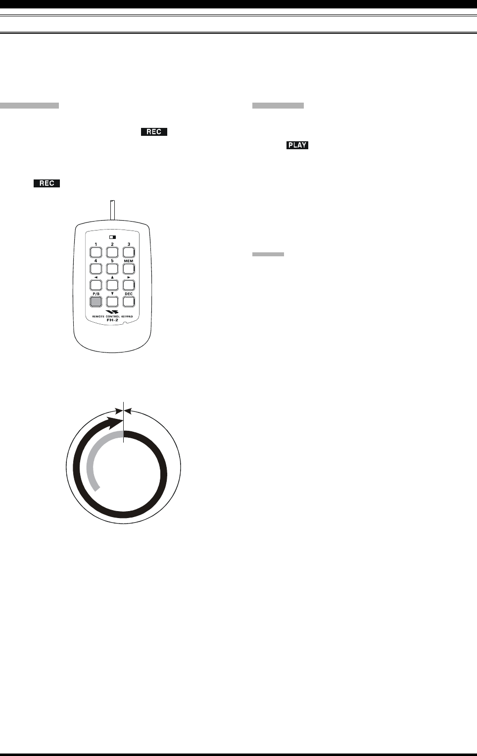
Page 45FTDX5000 OPERATING MANUAL
CONVENIENCE FEATURES
P.BACK (AUDIO PLAYBACK) FROM MAIN (VFO-A) RECEIVER
When Audio Playback is engaged by the operator, the FTDX5000 begins automatically recording the last 15 seconds of
incoming receiver audio on VFO-A. Recording is controlled with the supplied FH-2 Remote Control Keypad, plugged into
the rear panel REMOTE jack. This capability is especially useful for confirming a callsign that may have been difficult to
copy due to noise or QRM, etc.
Recording
Press and hold in the FH-2’s [P/B] key for two sec-
onds to initiate recording. The “ ” icon will ap-
pear in the display to confirm that recording is in
progress.
Press the FH-2’s [P/B] key briefly to halt recording;
the “ ” icon will go out.
LOCK
OFFON
Playback
Press the FH-2’s [P/B] key briefly, after recording has
been halted, to begin playback of the recorded audio;
the “ ” icon will appear in the display to confirm
that playback is in progress. The last 15 seconds of
audio will be heard in the speaker or headphones. If
you do not intervene, the entire 15 seconds will be
played back, repeating endlessly.
To halt playback at any time, just press the [P/B] key
briefly again. The next time you press the [P/B] key, it
will pick up the playback where you left off.
ADVICE
You may adjust the playback level of the recording with
the main [AF GAIN] knob.
Start
Stop
15 Seconds
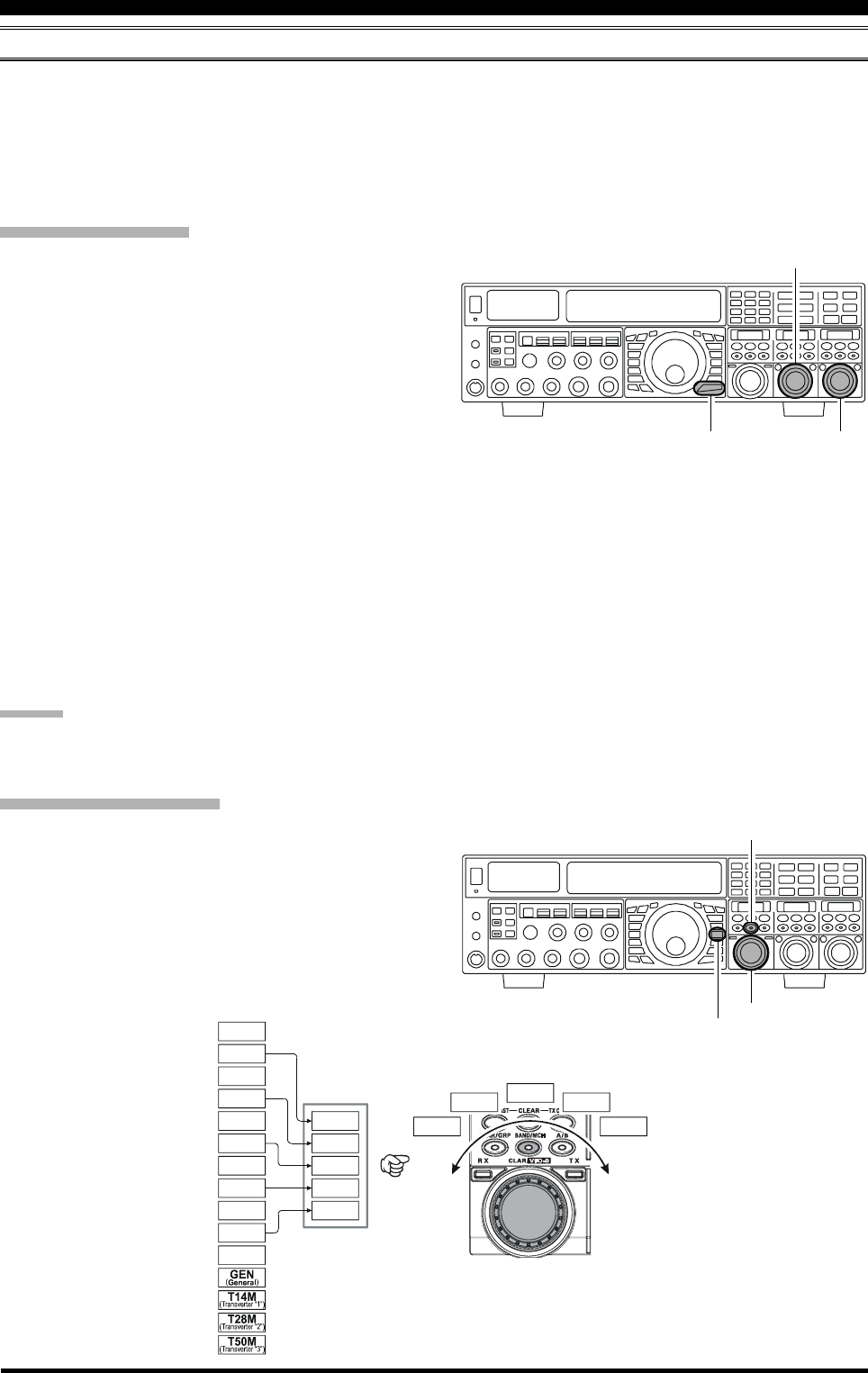
Page 46 FTDX5000 OPERATING MANUAL
“MY BANDS” OPERATION
When operating on an amateur band, it is possible to use the [CLAR(VFO-B)] knob to change the selected operating band.
The “My Bands” feature allows you to designate several amateur bands, and make only those bands available for selection
with the [CLAR(VFO-B)] knob.
This feature can be very useful in a contest, where the 10/18/24 MHz bands are not used, or if you do not have antennas for
some bands.
“My Bands” Setup
1. Press the [MENU] button to engage the Menu mode.
2. Rotate the (VFO-A)[SELECT] knob to select Menu
item “150 TUN MY BAND”.
3. Rotate the (VFO-B)[SELECT] knob to choose a band
that you wish to skip (omit) from the band-selection
loop (when using the [CLAR(VFO-B)] knob for band
selection). The available choices are 1.8M/3.5M/7M/
10M/14M/18M/21M/24M/28M/50M/GEN(General
Band)/T14M(Transverter “1”)/T28M(Transverter
“2”)/T50M(Transverter “3”).
4. Press the [ENT] button (one of the [BAND] buttons)
to set the selected band to “skipped”. The “ON” nota-
tion at the right of the band notation will change to
“OFF”.
5. Repeat steps 3 and 4 to select (“ON”) or deselect
(“OFF”) as many bands as you like.
6. Press and hold in the [MENU] button for two seconds
to lock in the new configuration and exit to normal
operation.
ADVICE:
The “My Band” feature affects only VFO-A band.
CONVENIENCE FEATURES
“My Band” Operation
1. Press the [V/M] button once, if neccessary, to enter the
“VFO” mode.
2. Press the [BAND/MCH] button briefly; the button will
glow Red.
3. Rotate the [CLAR(VFO-B)] knob to choose the ama-
teur band on which you wish to operate. Only those
amateur bands that have not been skipped will appear
as you scroll through the bands.
(VFO-B)[SELECT] Knob
[MENU] Button
(VFO-A)[SELECT] Knob
[CLAR(VFO-B)] Knob
[V/M] Button
[BAND/MCH] Button
14 MHz
14 MHz
18 MHz
50 MHz
21 MHz21 MHz
7 MHz
7 MHz
5 MHz
1.8 MHz
28 MHz
28 MHz
24 MHz
3.5 MHz
3.5 MHz
10 MHz
14 MHz
21 MHz7 MHz
28 MHz3.5 MHz
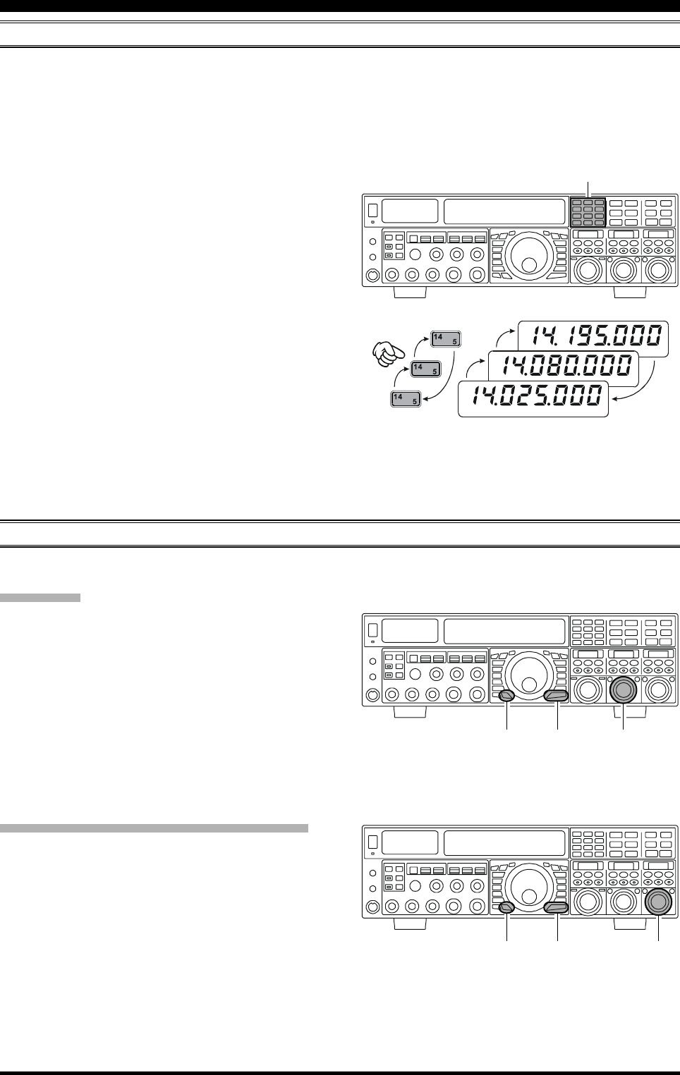
Page 47FTDX5000 OPERATING MANUAL
CONVENIENCE FEATURES
BAND STACK OPERATION
The FTDX5000 utilizes a triple band-stack VFO selection technique that permits you to store up to three favorite frequen-
cies and modes onto each band’s VFO register. For example, you may store one frequency each on 14 MHz CW, RTTY, and
USB, then recall each VFO by successive, momentary presses of the [14] MHz band button. Each Amateur band key may
similarly have up to three frequency/mode settings applied. Both the VFO-A and VFO-B systems have their own, indepen-
dent, band stacks.
A typical setup, for the 14 MHz band, might be arranged
like this:
1. Program 14.025 MHz, CW Mode, then press the [14]
MHz band button;
2. Program 14.080 MHz, RTTY Mode, then press the [14]
MHz band button;
3. Program 14.195 MHz, SSB Mode, then press the [14]
MHz band button.
With this configuration, successive momentary presses of
the [14] MHz band button will allow you to toggle se-
quentially through these three VFO configurations.
C.S (CUSTOM SWITCH)
An often-used Menu mode selection may be programmed to the front panel [C.S] button.
C.S Setup
1. Press the [MENU] button to engage the Menu mode;
the Menu list will appear on the SUB DISPLAY win-
dows.
2. Rotate the (VFO-A)[SELECT] knob to select the
Menu item you want to be able to access via the [C.S]
button.
3. Press and hold in the [C.S] button for two seconds to
lock in your selection.
4. Press and hold in the [MENU] button for two seconds
to save the new configuration and exit to normal op-
eration.
Menu Selection Recall via [C.S] button
1. Press the [C.S] button. The programmed Menu item
will appear on the display.
2. You may now rotate the (VFO-B)[SELECT] knob to
change the setting of this menu item.
3. Press the [MENU] button for two seconds, when you
are done, to save the new configuration and exit to
normal operation.
USB
RTTY
CW
(VFO-A)[SELECT] Knob
[MENU] Button
[C.S] Button
(VFO-B)[SELECT] Knob
[MENU] Button
[C.S] Button
[BAND] Button
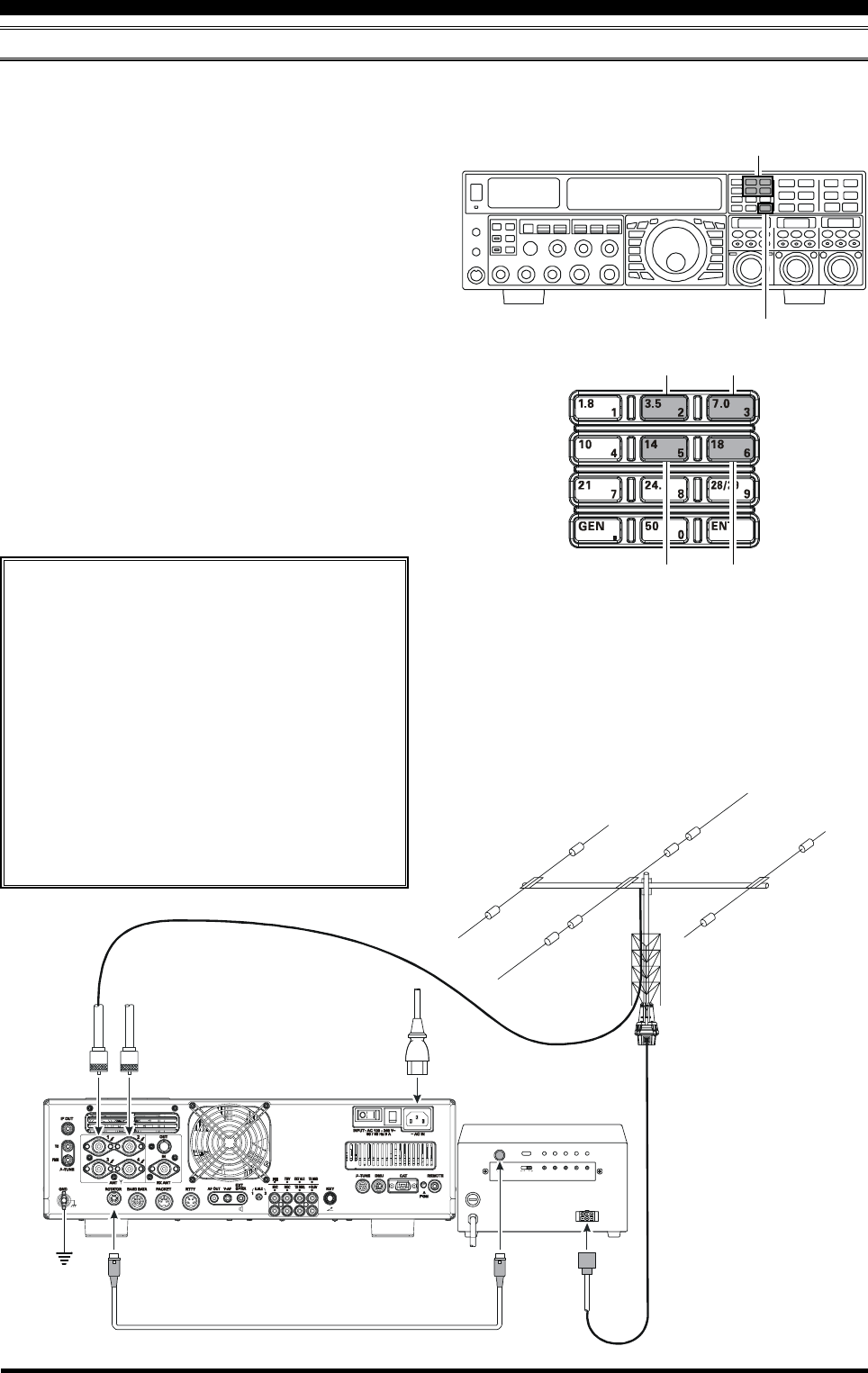
Page 48 FTDX5000 OPERATING MANUAL
ROTATOR CONTROL FUNCTIONS
When using a YAESU model G-800DXA, G-1000DXA, or G-2800DXA rotator (not supplied), it is possible to control it
from the front panel of the FTDX5000.
1 Press and hold in the [ENT] button (one of the [BAND]
buttons) for two seconds. The SUB DISPLAY win-
dows will change, and display the “Rotator Control”
configuration.
2 Press either the [3.5(2)] button or the [7.0(3)] button
to rotate the antenna. Pressing the [3.5(2)] button will
cause rotation to the left (counter-clockwise), while
pressing the [7.0(3)] button will cause rotation to the
right (clockwise).
3 Press the [14(5)] button or the [18(6)] button to con-
trol the speed of rotation. Pressing the [14(5)] button
will cause slower rotation, while pressing the [18(6)]
button will speed up rotation. Usually, you will be us-
ing the “100%” setting.
When you are through exercising rotator control, press the
[ENT] button briefly. The SUB DISPLAY windows will
return to the normal display.
CONVENIENCE FEATURES
IMPORTANT NOTE
Set the FTDX5000 to match the starting point
of your rotator control indicator needle via
Menu item “014 DISP RTR STU”. The default
setting is “0°” (north). If your controller start-
ing point is south, the Menu item “014 DISP
RTR STU” must be set to “180°”. If not set
properly the FTDX5000 display will not show
the correct direction.
When the rotator control indicator needle does
not indicate the precise antenna direction, ad-
just the indicator needle precisely to the antenna
direction via Menu item “015 DISP RTR ADJ”.
[ENT] Button
[3.5(2)], [7(3)] Button
[14(5)], [18(6)] Button
ANT 1
~AC IN
ANT 2
EXT CONTROL
REMOTE
CONTROL
ROT
EXT
CONT ROL
SELECT
SWITCH
PRESET
ADJ
OPERATION
MODE
ADJ. MODE F ULL
SCALE
ADJ
OVERLAP
LED ADJ
OUT VOL
ADJ
AB
OPTIONAL CONNECTION CABLE
()
T9101556
Counter-clockwise Rotation Clockwise Rotation
Speed Down Speed Up

Page 49FTDX5000 OPERATING MANUAL
MORE FREQUENCY NAVIGATION TECHNIQUES
Keyboard Frequency Entry
You may enter operating frequencies, for either the VFO-
A or VFO-B bands, using the front panel band/frequency
selection keys.
Example 1: Enter 14.250.000 MHz into VFO-A
1. Press the [ENT] button to engage the direct frequency
entry process. Now, be-
ginning with the “10
MHz” digit of the fre-
quency (the leftmost
digit), we will enter the
required digits of the fre-
quency.
2. Press, in order, the digits of the operating frequency,
using the [BAND] buttons (which have the frequency-
entry digit or decimal point on the right side of the
slash bar). In this example, enter
[1.8/1] [10/4] [GEN/.] [3.5/2]
[14/5] [50/0] [50/0] [50/0] [50/0]
The decimal point after the “MHz” portion of the fre-
quency must be entered, but no decimal point is re-
quired after the “kHz” portion.
3. Press the [ENT] button once more. A short “beep” will
confirm that the frequency entry was successful, and
the new operating frequency will appear on the Main
(VFO-A) frequency display fields.
Example 2: Enter 7.100.000 MHz into VFO-B
1. Press the [B] button, lo-
cated to the upper left of
the Main Tuning Dial
knob. The [B] button
will glow orange.
2. Press the [ENT] button
to engage the direct frequency entry process. Now,
beginning with the “10 MHz” digit of the frequency
(the leftmost digit), we will enter the required digits of
the frequency to be entered into the VFO-B register.
3. Press, in order, the digits of the operating frequency,
using the [BAND] buttons (which have the frequency-
entry digit or decimal point on the right side of the
slash bar). In this example, enter
[21/7] [GEN/.] [1.8/1]
[50/0] [50/0] [50/0] [50/0] [50/0]
4. Press the [ENT] button once more. A short “beep” will
confirm that the frequency entry was successful, and
the new operating frequency will appear on the VFO-
B frequency display, SUB DISPLAY-
I
window.
ADVICE:
If you attempt to enter a frequency outside the operat-
ing range of 30 kHz ~ 60 MHz, the microprocessor
will ignore the attempt, and you will be returned to
your previous operating frequency. If this happens,
please try again, taking care not to repeat the error in
the frequency entry process.
Using the [(DOWN)]/[(UP)] Buttons
To tune the VFO-A frequency in 1 MHz step. Press the
[(UP)] or [(DOWN)] but-
ton.
To tune the VFO-B frequency in 1 MHz step. Press the
[B] button first (The [B] button will glow orange), then
press the [(UP)] or [(DOWN)] button.
ADVICE:
You may change the tuning step of the [(UP)]/
[(DOWN)] buttons to 100 kHz via the Menu item “144
TUN MHz SEL”. See page 133.
Using the [UP]/[DWN] Switches of the
Supplied MH-31B8 Hand Microphone
The [UP]/[DWN] switches on the supplied MH-31B8 Hand
Microphone may also be used for manually scanning up-
ward or downward in frequency.
The microphone [UP]/[DWN] switches utilize the tuning
steps of the Main Tuning Dial
knob; moreover, when the mi-
crophone [FAST] key is
pressed, the tuning rate will change
to 100 Hz, similar to the effect of
the transceiver front-panel [FAST]
button.
ADVICE:
In the AM and FM modes, you may in-
dependently set the tuning steps when
using the [UP]/[DWN] switches. To set
new tuning steps, use Menu items “145
TUN AM STEP” and “146 TUN FM
STEP”.
CONVENIENCE FEATURES
DYNAMIC MICROPHONE
MH-31
DWN F ST UP
[DWN] Button
[FST] Button
[UP] Button
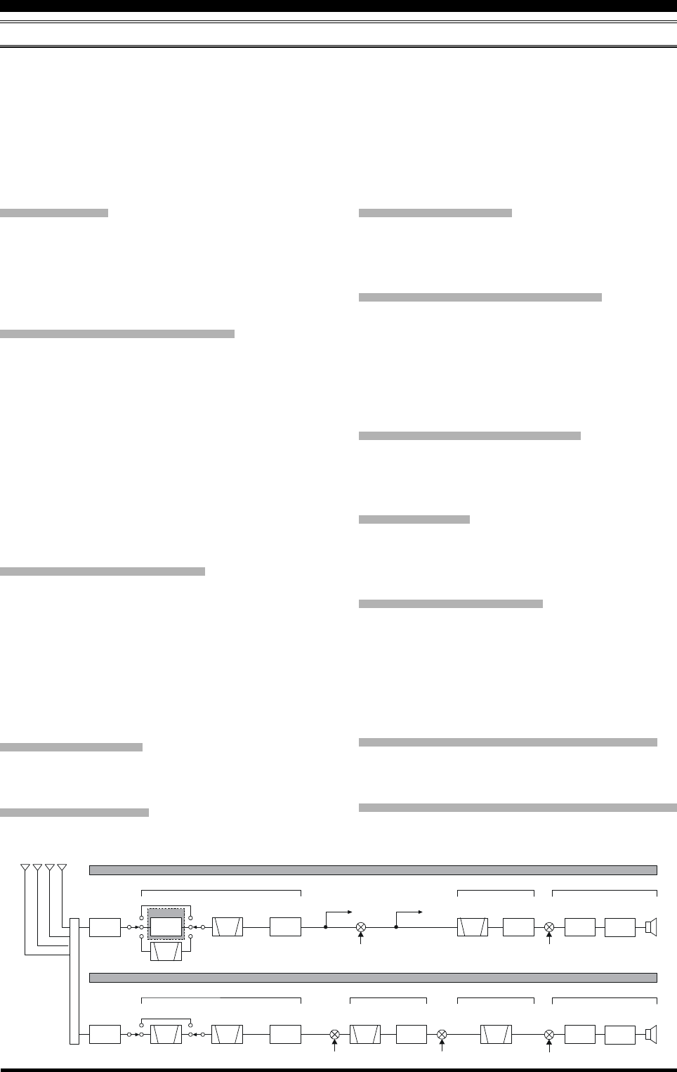
Page 50 FTDX5000 OPERATING MANUAL
RECEIVER OPERATION (FRONT END BLOCK DIAGRAM)
The FTDX5000 includes a wide range of special features to suppress the many types of interference that may be encoun-
tered on the HF bands. However, real world interference conditions are constantly changing, so optimum setting of the
controls is somewhat of an art, requiring familiarity with the types of interference and the subtle effects of some of the
controls. Therefore, the following information is provided as a general guideline for typical situations, and a starting point
for your own experimentation.
Yaesu provides the optional RF-µTUNING Unit (Narrow-bandwidth High-Q RF Filter) for additional protection from
strong signal interference.
VRF (SEE PAGE 54)
On the 1.9 - 28 MHz amateur bands, Yaesu’s powerful
VRF (Variable RF Filter) preselector circuit provides ex-
cellent suppression of out-of-band interference. The pass-
band is much narrower than that provided by traditional
fixed bandpass filters.
R. FLT (IF Roofing Filters) (SEE PAGE 56)
On the VFO-A receiver, Roofing filters, in bandwidths of
15 kHz, 6 kHz, 3 kHz, 600Hz, and 300 Hz (optional in
some models), are provided in the 9 MHz First IF, right
after the first mixer. These filters provide narrow-band se-
lectivity to protect the following IF and DSP stages. The
15 kHz, 6 kHz, or 3 kHz filters are automatically selected
for typical operating modes, and may be manually changed
by the operator, if desired, for special operating circum-
stances.
The VFO-B receiver 40 MHz IF includes three Roofing
filters, with bandwidths of 15 kHz, 6 kHz, and 3 kHz.
CONTOUR Filter (SEE PAGE 58)
The DSP Contour filter is a unique capability of the
FTDX5000, providing either nulling or peaking of tunable
segments of the receiver passband. The Contour filter can
suppress interference, or excessive frequency components
on an incoming signal, or it can peak those tunable fre-
quency segments. The amount of nulling/peaking, and the
bandwidth over which it is applied, are adjustable via the
Menu.
IF SHIFT (SEE PAGE 60)
The passband center frequency response of the IF DSP
filtering may be adjusted using this control.
IF WIDTH (SEE PAGE 61)
The width of the IF DSP filtering may be adjusted using
this control.
IF NOTCH (SEE PAGE 63)
The IF Notch filter is a high-Q notch filter that can signifi-
cantly reduce, or eliminate, an interfering carrier. The Q
(sharpness) of the filter may be adjusted using the Menu.
DNR (DIGITAL NOISE REDUCTION) (SEE PAGE 64)
The DSP’s Digital Noise Reduction (DNR) feature uti-
lizes sixteen different mathematical algorithms to analyze
and suppress different noise profiles encountered on the
HF/50 MHz bands. Choose the selection that provides the
best noise suppression, which concurrently will allow the
signal to rise up out of the noise.
DNF (DIGITAL NOTCH FILTER) (SEE PAGE 64)
When multiple interfering carriers are encountered during
reception, the Digital Notch Filter can significantly reduce
the level of these signals.
AGC (SEE PAGE 67)
The AGC system is highly adaptable to changing signal
and fading characteristics, making reception possible un-
der the most difficult conditions.
SLOPED AGC (SEE PAGE 68)
Instead of limiting a wide range of audio output signals to
a fixed upper bound, the sloped AGC system actually al-
lows the audio output to rise, very gently, with ever-in-
creasing signal strength. This capability allows you to men-
tally separate signals, according to signal strength, in ad-
dition to slight frequency differences.
IF Filter Quality Adjustment (SEE PAGE 131)
The “Q” (quality factor) of the IF DSP filters may be ad-
justed using the Menu.
Variable IF Filter Shape Factor (SEE PAGE 131)
You may adjust the shape factor of the receiver IF DSP
filters using the Menu.
CONVENIENCE FEATURES
ROOFING
FILTER
ROOFING
FILTER
RF
SCOPE IF OUT
RF
1st IF
1st IF 2nd IF
2rd IF
(DSP)
3rd IF
(DSP)
9 MHz
40.455 MHz 455 kHz
30 kHz (SSB/CW)
24 kHz (AM/FM)
30 kHz (SSB/CW)
24 kHz (AM/FM)
BPF
BPF
RF AMP/
IPO
1st
IF AMP
1st
IF AMP
DSP
UNIT
DSP
UNIT
1st Local
1st Local
300Hz
600Hz
3kHz
6kHz
15kHz
3kHz
6kHz
15kHz
2nd Local
2nd Local 3rd Local
CF
VRF
VRF
µ-TUNE
VFO-A Receiver
VFO-B Receiver
OPTION
ATT
ATT
THRU
THRU
ANTENNA SELECTOR
RF AMP/
IPO
2nd
IF AMP
3rd
IF AMP
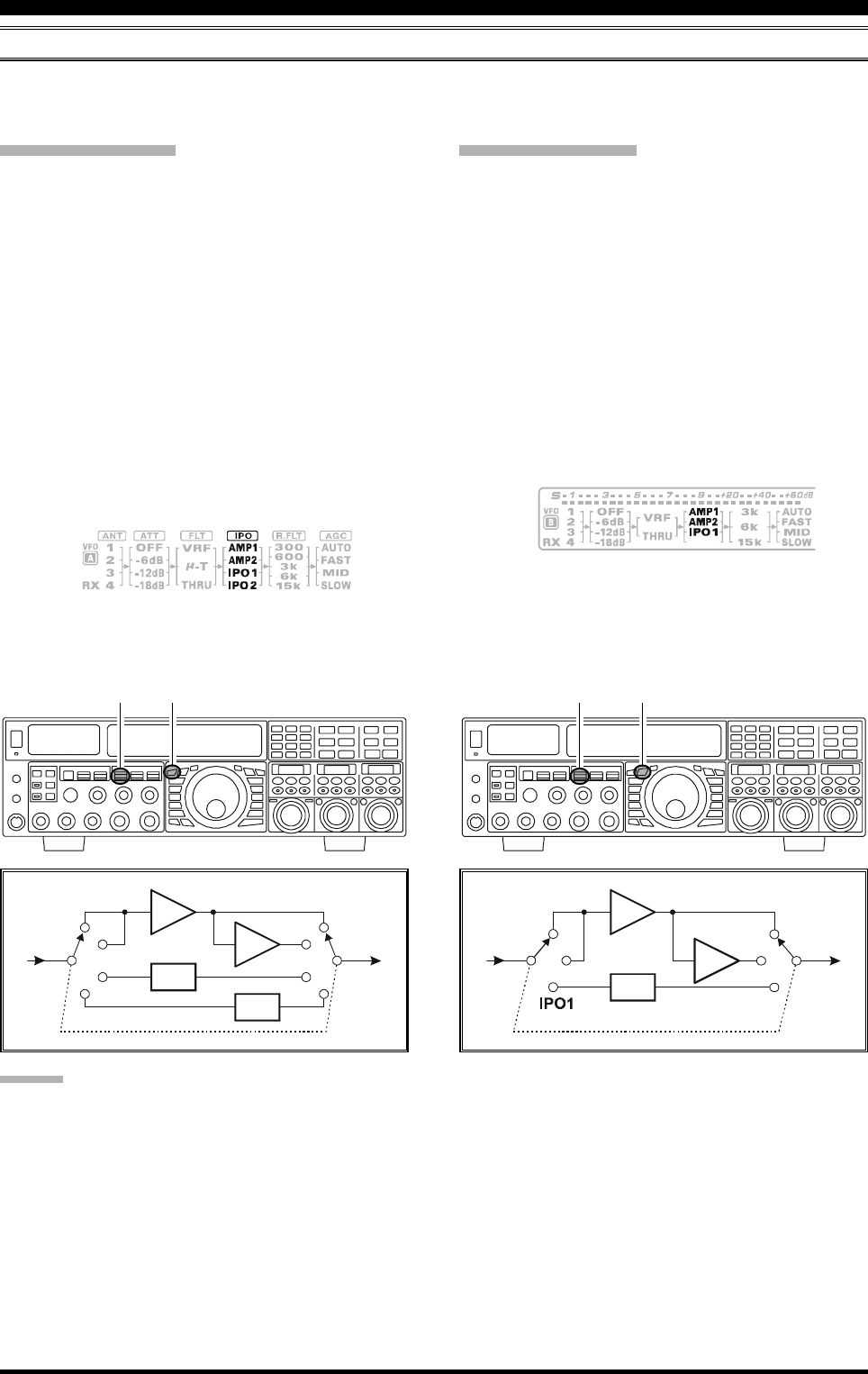
Page 51FTDX5000 OPERATING MANUAL
IPO (INTERCEPT POINT OPTIMIZATION)
The IPO feature allows the operator to optimize the characteristics of the receiver front end, depending on the current noise
level and the strength of incoming signals.
VFO-A IPO Setup
Press the [A] button to activate VFO-A receiver (The
[A] button will glow red).
Move the [IPO] knob up or down to set the desired
characteristic of the VFO-A receiver front end, per the
chart below.
AMP1: Amplifies the incoming signal, using a low
distortion RF preamplifier (normally, the IPO
is set to this position).
AMP2: Increases receiver sensitivity.
IPO1: Improves the IPO.
IPO2: Bypasses the RF preamplifier, yielding di-
rect feed to the first mixer. As a result, the
IPO is improved more.
The selected receiver RF preamplifier will be indicated
in the IPO column of the Block Diagram Display.
CONVENIENCE FEATURES
VFO-B IPO Setup
Press the [B] button to activate VFO-B receiver (The
[B] button will glow orange).
Move the [IPO] knob up or down to set the desired
characteristic of the VFO-B receiver front end, per the
chart below.
AMP1: Amplifies the incoming signal, using a low
distortion RF preamplifier (normally, the IPO
is set to this position).
AMP2: Increases receiver sensitivity.
IPO1: Improves the IPO.
The selected receiver RF preamplifier will be indicated
in the IPO column of the Block Diagram Display.
ADVICE:
On the 10 MHz and lower bands, it generally is not necessary to use any preamplifier at all; selecting the “IPO” position as
described above will increase the strong-signal-handling capability of the receiver, and usually result in more pleasant
reception due to reduced noise. If you can hear band noise with the preamplifiers disengaged, then a preamplifier is gener-
ally not needed.
[A] Button
[IPO] Knob [B] Button
[IPO] Knob
Press the [IPO] knob briefly, to quickly set the IPO to
“AMP1”.
Press the [IPO] knob briefly, to quickly set the IPO to
“AMP1”.
AMP1
IPO1
IPO2
AMP
AMP
AMP2
IPO1
IPO2
IPO1
AMP1
AMP
AMP
AMP2
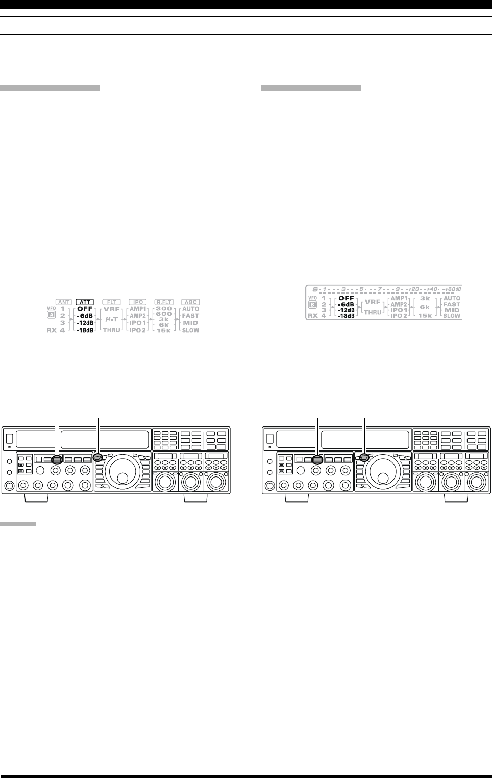
Page 52 FTDX5000 OPERATING MANUAL
ATT
Even with the IPO function on, extremely strong local signals or high noise can still degrade reception. In such situations,
you can use the [ATT] button to insert 6, 12, or 18-dB of RF attenuation in front of the RF amplifier.
VFO-A IPO Setup
Press the [A] button to activate VFO-A receiver (The
[A] button will glow red).
Move the [ATT] knob up or down to set the desired
attenuation level of the VFO-A receiver, per the chart
below.
OFF: Attenuator is Off
–6 dB: The incoming signal power is reduced by 6
dB (Signal voltage reduced by 1/2)
–12 dB: The incoming signal power is reduced by 12
dB (Signal voltage reduced to 1/4)
–18 dB: The incoming signal power is reduced by 18
dB (Signal voltage reduced to 1/8)
The selected attenuation level will be indicated in the
ATT column of the Block Diagram Display.
VFO-B IPO Setup
Press the [B] button to activate VFO-B receiver (The
[B] button will glow orange).
Move the [ATT] knob up or down to set the desired
attenuation level of the VFO-B receiver, per the chart
below.
OFF: Attenuator is Off
–6 dB: The incoming signal power is reduced by 6
dB (Signal voltage reduced by 1/2)
–12 dB: The incoming signal power is reduced by 12
dB (Signal voltage reduced to 1/4)
–18 dB: The incoming signal power is reduced by 18
dB (Signal voltage reduced to 1/8)
The selected attenuation level will be indicated in the
ATT column of the Block Diagram Display.
ADVICE:
If background noise causes the S-meter to deflect on clear frequencies, move the [ATT] knob until the S-meter drops to
about “S-1”. This setting optimizes the trade-offs between sensitivity, noise, and interference immunity. Also, once you
have tuned in a station you want to work, you may want to reduce sensitivity further (or add more attenuation) by moving
the [ATT] knob to a greater setting. This reduces the strength of all signals (and noise) and can make reception more
comfortable, important especially during long QSOs. When looking for weak signals on a quiet band, you will want maxi-
mum sensitivity, so the IPO should be disabled and the [ATT] knob should be set to “OFF” by pressing the [ATT] knob. This
situation is typical during quiet times on frequencies above 21 MHz, and when using a small or negative-gain receiving
antenna on other bands.
To quickly restore full signal strength through the At-
tenuator circuit, press the [ATT] knob in briefly to re-
store the ATT display to the “OFF”.
To quickly restore full signal strength through the At-
tenuator circuit, press the [ATT] knob in briefly to re-
store the ATT display to the “OFF”.
[A] Button
[ATT] Knob [B] Button
[ATT] Knob
CONVENIENCE FEATURES
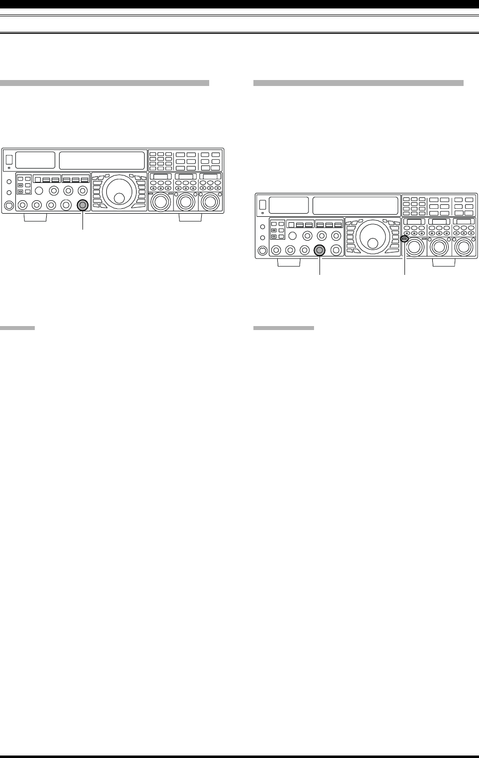
Page 53FTDX5000 OPERATING MANUAL
CONVENIENCE FEATURES
RF GAIN (SSB/CW/AM MODES)
The RF Gain controls permit manual adjustment of the receiver RF and IF stages gain levels, to account for noise and/or
signal strength conditions.
VFO-A Receiver RF GAIN Adjustment
The (VFO-A)[RF GAIN] knob should, be rotated, initially,
to the clockwise position. This is the point of maximum
sensitivity, and counter-clockwise rotation will gradually
reduce the receiver RF gain.
VFO-B Receiver RF GAIN Adjustment
The VFO-B receiver RF Gain operates identically to the
VFO-A receiver RF Gain.
Press the (VFO-B)[RX] button to engage the Dual
Receive operation. The (VFO-B)[RX] button will glow
green.
Always utilize the fully clockwise position of the (VFO-
B)[RF GAIN] knob as the starting point for operation.
ADVICE:
As the [RF GAIN] knob is rotated counterclockwise
to reduce the gain, the S-meter reading will rise. This
indicates that the AGC voltage being applied to the
receiver is increasing (which causes a reduction in re-
ceiver gain).
Rotating the [RF GAIN] knob control to the fully
counter-clockwise position will essentially disable the
receiver, as the gain will be greatly reduced. In this
case, as well, the S-meter will appear to be “pegged”
against the right edge of the analog S-meter scale.
The (VFO-B)[RF GAIN] knob operates identically to
the (VFO-A)[RF GAIN] knob. The effects of counter-
clockwise rotation of the VFO-B receiver RF Gain
control may be observed visually on the VFO-B S-
meter.
QUICK POINT:
Reception can often be optimized by rotating the [RF
GAIN] knob slightly counter-clockwise, to the point
where the S-meter stationary needles position is just
about the same as the receiver noise level. This setting
ensures incoming signals will be heard with minimal
noise. The S/N (signal to noise) of the receiver will be
improved, without so much gain reduction that weak
signals cannot be heard.
The RF GAIN control, along with the IPO and ATT
(attenuator) features, all affect the system receiver gain
in different ways. As a first step in dealing with high
noise or a crowded, high-level signal environment, the
IPO generally should be the first feature engaged, if
the frequency is low enough to allow the preamplifier
to be bypassed. Thereafter, the RF GAIN and ATT (at-
tenuator) features may be employed to provide pre-
cise, delicate adjustment of the receiver, and fully op-
timize performance.
(VFO-A)[RF GAIN] Knob
(VFO-B)[RF GAIN] Knob (VFO-B)[RX] Button
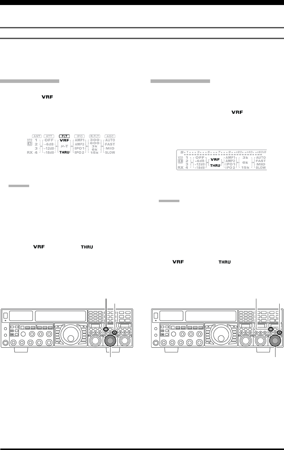
Page 54 FTDX5000 OPERATING MANUAL
The FTDX5000 includes an unmatched array of RF selectivity-enhancing features. Please study the following material
carefully, to understand the many interference tools and techniques completely.
USING THE VRF (VARIABLE RF FRONT-END FILTER)
The VRF system is a high-performance RF front-end preselector that has a high Q factor and low insertion loss. VRF
provides outstanding rejection of out-of-band signals, it can also significantly improve receiver performance when located
near other transmitters, such as a contest or DX-pedition station. The FTDX5000 VRF system affects the 1.8 - 28 MHz
amateur bands only.
A
DVANCED
I
NTERFERENCE
-S
UPPRESSION
F
EATURES
:
RF F
RONT
E
ND
VFO-A VRF Setup
Press the (VFO-A)[VRF] button. The button will glow
red, and the “ ” icon will appear at the FLT col-
umn of the Block Diagram Display. The VRF system
will be engaged and centered on the currently operat-
ing amateur band. The (VFO-A)[SELECT] knob will
now function as the VRF adjusting knob.
VFO-B VRF Setup
Press the (VFO-B)[RX] button to engage Dual Receive
operation. The button will glow green.
Press the (VFO-B)[VRF] button. The (VFO-B)[VRF]
button will glows red, and the “ ” icon will appear
at the FLT column of the Block Diagram Display. The
VRF system will be engaged and centered on the cur-
rent operating amateur band. The (VFO-B)[SELECT]
knob will now function as the VRF adjusting knob.
(VFO-A)[SELECT] Knob
[CLEAR] Button
(VFO-A)[VRF/µ-T] Button
(VFO-B)[SELECT] Knob
[CLEAR] Button
(VFO-B)[VRF] Button
You may rotate the (VFO-A)[SELECT] knob to
change the VRF system tuning, relative to your oper-
ating frequency.
ADVICE:
You may observe the relative skew of the VRF sys-
tem in the SUB DISPLAY-II . window.
After moving the passband of the VRF system
manually, you may re-center it on the current Ama-
teur band by pressing the (VFO-A)[CLEAR] but-
ton.
To switch VRF off, press the (VFO-A)[VRF] button
until the “ ” icon shows “ ” in the FLT col-
umn of the Block Diagram Display; this confirms that
the VRF circuit has been removed from the incoming
received signal path.
You may rotate the (VFO-B)[SELECT] knob to
change the VRF system tuning, relative to your oper-
ating frequency.
ADVICE:
You may observe the relative skew of the VRF sys-
tem in the SUB DISPLAY-III window.
After moving the passband of the VRF system
manually, you may re-center it on the current Ama-
teur band by pressing the (VFO-B)[CLEAR] but-
ton.
To switch VRF off, press the (VFO-B)[VRF] button.
The “ ” icon shows “ ” in the FLT column of
the Block Diagram Display; this confirms that the VRF
circuit has been removed from the incoming received
signal path.
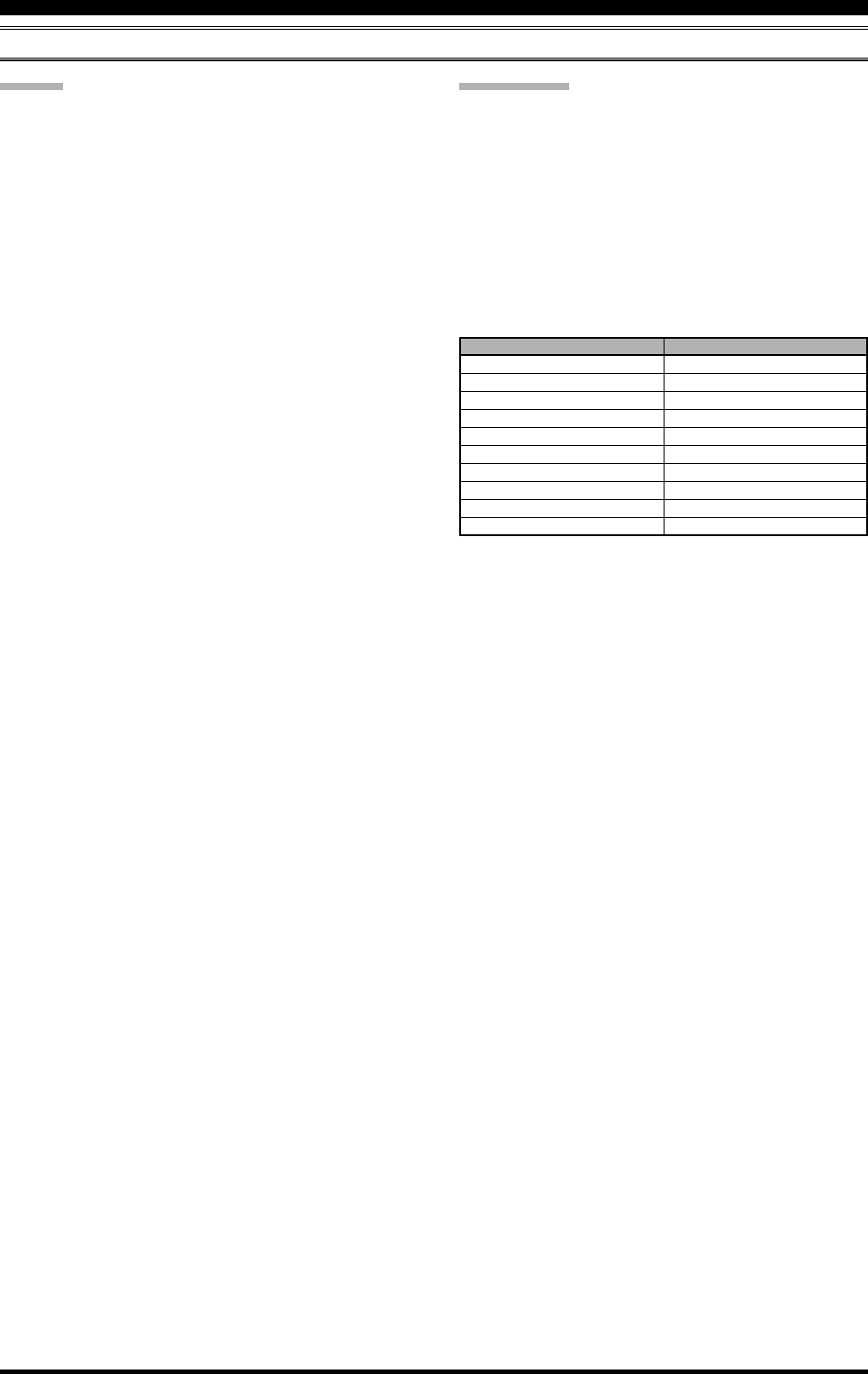
Page 55FTDX5000 OPERATING MANUAL
ADVICE:
The VRF system tuning is relatively broad, although it
is still much narrower than the fixed bandpass filter.
You may not hear much difference in the background
noise or signal quality when you make minor adjust-
ments. However, if you have receiving problems asso-
ciated with a very strong signal, rotation of the [SE-
LECT] knob may help reduce the strength of the inter-
fering station, allowing improved reception of the de-
sired signal, if receiver overload was degrading recep-
tion.
The VRF Filter operational status will be memorized
independently on each VFO in the VFO stack.
You may select the display pattern shown in the SUB
DISPLAY window from three patterns via Menu item
“019 DISP SELECT”. See page 122 for details.
QUICK POINT:
The VRF filter utilizes high-quality coils and capacitors
that provide high Q, and yield a passband that is approxi-
mately 20% to 30% the width of a traditional, fixed
bandpass filter. As a result, significantly more “unwanted”
signal rejection is provided. Within each amateur band,
the following adjustment steps are provided, if you wish
to skew the response in a particular direction to enhance
interference rejection even more. The actual “sound” of
the signal you are listening to will remain unchanged, how-
ever.
AMATEUR BAND
1.8 MHz
3.5 MHz
5 MHz
7 MHz
10 MHz
14 MHz
18 MHz
21 MHz
24.5 MHz
28 MHz
VRF ADJUSTMENT STEPS
62 steps
62 steps
62 steps
62 steps
30 steps
30 steps
20 steps
20 steps
20 steps
20 steps
A
DVANCED
I
NTERFERENCE
-S
UPPRESSION
F
EATURES
:
RF F
RONT
E
ND
USING THE VRF (VARIABLE RF FRONT-END FILTER)
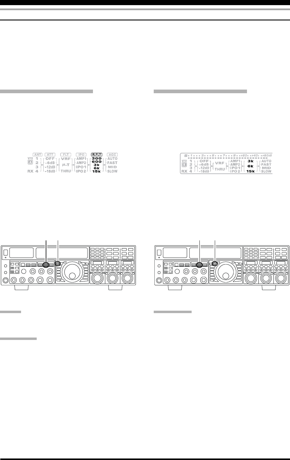
Page 56 FTDX5000 OPERATING MANUAL
R.FLT (ROOFING FILTERS)
Narrow-band Roofing Filters of 15 kHz, 6 kHz, 3 kHz, 600 Hz, and 300 Hz bandwidths are provided in the first IF, right
after the first mixer. These filters provide protection for the 2nd mixer, DSP, and other circuitry that follow. The roofing
filter can dramatically improve reception on a very crowded band (during a contest, etc.). Typically, the AUTO selection
mode is satisfactory for most operating situations, but in an extremely crowded phone or CW band you may wish to select
a narrower filter. For example, the 3 kHz roofing filter for SSB operation, or the 600 Hz filter for CW.
:The 600 Hz roofing filter is only available on VFO-A. The 300Hz filter for VFO-A on the FTDX5000, is optional on
other versions.
I
NTERFERENCE
R
EJECTION
(S
IGNALS
O
FF
F
REQUENCY
BY
J
UST
A
F
EW
KHZ
)
VFO-A Roofing Filter Setup
Press the [A] button (the button will glow red), to acti-
vate the VFO-A receiver.
Move the [R.FLT] knob up and down to set the de-
sired bandwidth of the VFO-A Roofing Filter.
The selected bandwidth of the Roofing Filter will be
indicated in the R.FLT column of the Block Diagram
Display.
VFO-B Roofing Filter Setup
Press the [B] button (the button will glow orange), to
activate the VFO-B receiver.
Move the [R.FLT] knob up and down to set the de-
sired bandwidth of the VFO-B Roofing Filter.
The selected bandwidth of the Roofing Filter will be
indicated in the R.FLT column of the Block Diagram
Display.
ADVICE:
The Roofing Filter selection will be memorized inde-
pendently on each VFO memory in the VFO stack.
QUICK POINT:
The AUTO mode Roofing Filter selections are shown
below:
AM/FM/FM-PKT: 15 kHz
LSB/USB/PKT: 6 kHz
CW/RTTY: 3 kHz
Press the [R.FLT] knob in briefly, to quickly set the
Roofing Filter to the “AUTO” selection. The filter will
be selected according to the operating mode. The indi-
cated bandwidth will blink for three seconds in the
Roofing Filter Display, and thereafter will appear con-
tinuously. Typically, the filter will be set to “AUTO”,
but may be easily changed when needed.
TERMINOLOGY:
A “Roofing Filter,” as its name implies, places a “Roof”
over the receiver’s IF system bandwidth. This “Roof” pro-
tects the circuitry downstream from strong signal over-
load interference, just as a roof on a house protects the
contents from rain and snow.
[A] Button
[R.FLT] Knob [B] Button
[R.FLT] Knob

Page 57FTDX5000 OPERATING MANUAL
I
NTERFERENCE
R
EJECTION
(S
IGNALS
O
FF
F
REQUENCY
BY
J
UST
A
F
EW
KHZ
)
NOTE
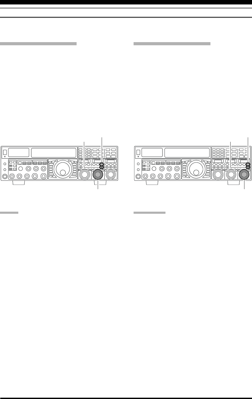
Page 58 FTDX5000 OPERATING MANUAL
CONTOUR CONTROL OPERATION
The Contour Filter system produces a gentle perturbation of the IF filter passband. The different frequency components of
the signal can be suppressed or enhanced, thus improving the sound and/or readability of the received signal.
I
NTERFERENCE
R
EJECTION
(S
IGNALS
WITHIN
3
KHZ
)
VFO-A Contour Operation
Press the (VFO-A)[CONT/APF] button. The button
will glow red and the position of the “null” (or “Peak”)
of the contour filter will be indicated in the SUB DIS-
PLAY-II window. The (VFO-A)[SELECT] knob will
now function as the contour knob.
Rotate the (VFO-A)[SELECT] knob to achieve the
most pleasing audio reproduction of the incoming sig-
nal.
Press the (VFO-A)[CLEAR] button in briefly, to
quickly move the “null” (or “Peak”) position to center.
To cancel Contour tuning, press the (VFO-A)[CONT/
APF] button once more.
ADVICE:
The contour filter null or peaking level may be adjusted
using Menu item “112 RDSP CNTR LV”. The factory
default null setting is “–15” (dB).
The bandwidth over which the contour null or peaking
affect is applied may be adjusted using Menu item “113
RDSP CNTR WI”. The factory default setting is “10”.
You may select the display pattern shown in the SUB
DISPLAY window from three patterns via Menu item
“019 DISP SELECT”. See page 122 for details.
When the optional DMU-2000 Data Management Unit
is connected, the Audio Scope (on the DMU-2000 “Os-
cilloscope” page) is particularly useful when adjusting
the Contour controls. You can see the affect of the
Contour system on the signal levels, and the position
of the null/peak with respect to frequency components
of interest. On the Audio Scope, you may visually ob-
serve the affect of the Contour Controls while listen-
ing to the signal, this will help build your intuition on
how best to use Contour tuning in the future.
VFO-B Contour Operation
Press the (VFO-B)[CONT/APF] button. The button
will glow red and the current “null” (or “Peak”) posi-
tion of the contour filter will be indicated in the SUB
DISPLAY-III window. The (VFO-B)[SELECT] knob
will now function as the contour knob.
Rotate the (VFO-B)[SELECT] knob to achieve the
most natural-sounding audio reproduction of the in-
coming signal.
Press the (VFO-B)[CLEAR] button in briefly, to
quickly move the “null” (or “Peak”) position to center.
To cancel Contour tuning, press the (VFO-A)[CONT/
APF] button once more.
(VFO-A)[SELECT] Knob (VFO-B)[SELECT] Knob
(VFO-B)[CONT/APF] Button
[CLEAR] Button
(VFO-A)[CONT/APF] Button
[CLEAR] Button
QUICK POINT:
When adjusted aggressively, the steep slopes of the DSP
filtering can impart an unnatural sound to an incoming sig-
nal. Often, a narrow bandwidth is not the key to improved
copy. The incoming signal itself may have undesirable or
excessive frequency components, especially in the low fre-
quency range around 100-400 Hz. By judicious use of the
Contour filter, the “shoulder” of the passband response
may be altered, or components removed from within the
passband, allowing the desired signal to rise above the
background noise and interference in a manner not ob-
tainable with other filtering systems.
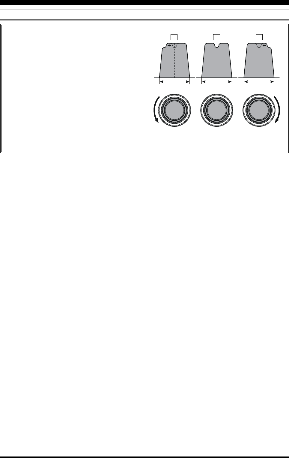
Page 59FTDX5000 OPERATING MANUAL
CONTOUR CONTROL OPERATION
I
NTERFERENCE
R
EJECTION
(S
IGNALS
WITHIN
3
KHZ
)
Refer to Figure “B”, and notice the initial position of
the contour when the [CONT] button is pushed. Ob-
serve the “indentation” in the receiver passband where
the contour filter is placing a low-Q “notch” (accord-
ing to the setting of Menu item “112 RDSP CNTR
LV”, as described on the previous page). Counter-
clockwise rotation of the [SELECT](contour) knob
causes the indentation to move toward a lower fre-
quency (to the left) within the passband, while clock-
wise rotation causes the indentation to move toward a
higher frequency (to the right) within the passband. By
removing the interference or unwanted frequency com-
ponents on the incoming signal, it is possible to make
the desired signal rise out of the background noise/
interference, and significantly enhance intelligibility.
IF
BANDWIDTH
IF
BANDWIDTH
IF
BANDWIDTH
ABC
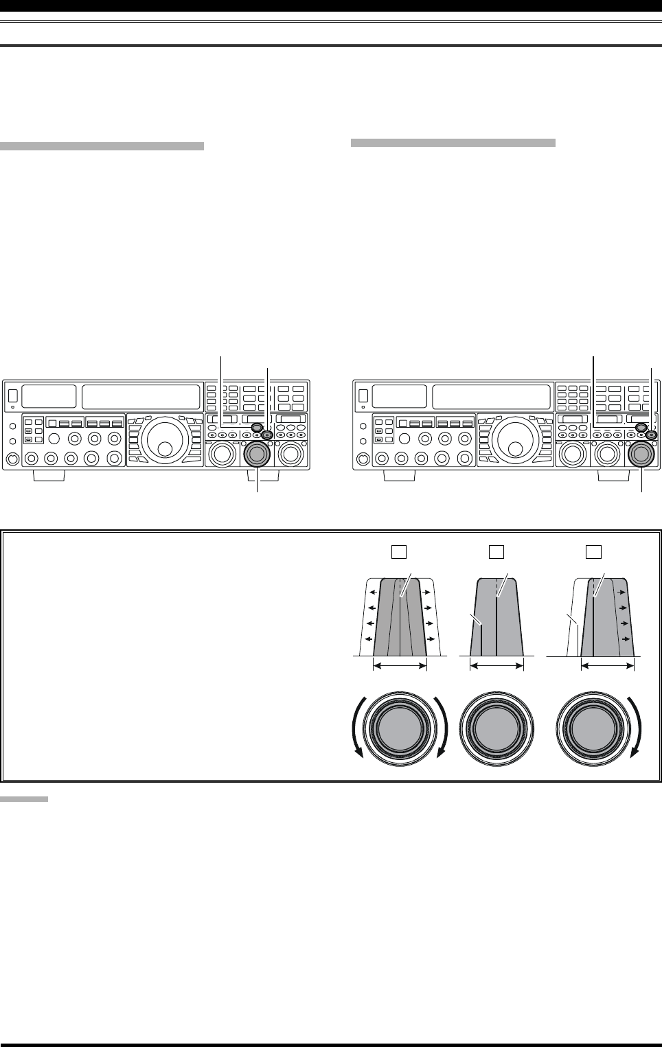
Page 60 FTDX5000 OPERATING MANUAL
IF SHIFT OPERATION (SSB/CW/RTTY/PKT/AM MODES)
The IF Shift allows you to vary the DSP filter passband higher or lower, (without changing the pitch of the incoming signal)
to reduce or eliminate interference. Because the carrier tuning frequency is not varied, there is no need to re-tune the
operating frequency when using the IF Shift to eliminating the interference. The total passband tuning range for the IF Shift
system is ±1 kHz.
I
NTERFERENCE
R
EJECTION
(S
IGNALS
WITHIN
3
KHZ
)
VFO-A IF SHIFT Operation
Press the (VFO-A)[SHIFT] button. The center posi-
tion of the IF passband will be indicated in the SUB
DISPLAY-II window. The (VFO-A)[SELECT] knob
will now function as the IF SHIFT knob.
Rotate the (VFO-A)[SELECT] knob to the left or right
to reduce the interference.
Press the (VFO-A)[CLEAR] button in briefly to
quickly move the filter passband to center. When the
filter passband is set to band center, the (VFO-
A)[SHIFT] button will glow red.
Refer to Figure “A” and notice the depiction of the IF
DSP filter as a thick line in the center of the passband,
no shift (the [SHIFT] button glows red). In Figure “B”,
an interfering signal has appeared inside the original
passband. In Figure “C”, you can see the effect of ro-
tating the [SELECT](shift) knob and moving the fil-
ter so that the interference is outside of the passband.
VFO-B IF SHIFT Operation
Press the (VFO-B)[SHIFT] button. The center posi-
tion of the IF passband will be indicated in the SUB
DISPLAY-III window. The (VFO-B)[SELECT] knob
will now function as the VFO-B IF SHIFT knob.
Rotate the (VFO-B)[SELECT] knob to the left or right
to reduce the interference.
Press the (VFO-B)[CLEAR] button in briefly to
quickly move the filter passband to center. When the
filter passband is set to band center, the (VFO-
B)[SHIFT] button will glow red.
(VFO-A)[SELECT] Knob (VFO-B)[SELECT] Knob
(VFO-B)[SHIFT] Button
[CLEAR] Button
(VFO-A)[SHIFT] Button
[CLEAR] Button
ABC
IF
BANDWIDTH
IF
BANDWIDTH
IF
BANDWIDTH
Desired Signal Desired Signal Desired Signal
QRMQRM
ADVICE:
You may select the display pattern shown in the SUB DIS-
PLAY window from three patterns via Menu item “019
DISP SELECT”. See page 122 for details.
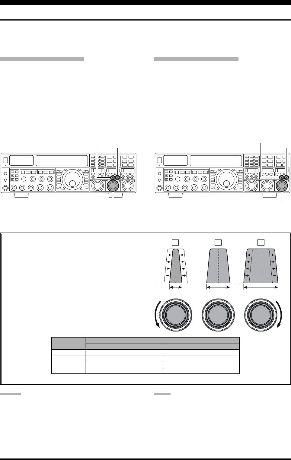
Page 61FTDX5000 OPERATING MANUAL
WIDTH (IF DSP BANDWIDTH) TUNING (SSB/CW/RTTY/PKT MODES)
The IF Width tuning system allows you to vary the width of the DSP IF filter passband, to eliminate interference. Moreover,
the bandwidth may actually be expanded from its default setting, should you wish to enhance incoming signal fidelity when
interference on the band is low.
I
NTERFERENCE
R
EJECTION
(S
IGNALS
WITHIN
3
KHZ
)
VFO-A WIDTH Operation
Press the (VFO-A)[WIDTH] button. The current band-
width will appear in the SUB DISPLAY-II window.
The (VFO-A)[SELECT] knob will now function as
the WIDTH knob.
Rotate the (VFO-A)[SELECT] knob to the left or right
to reduce the interference.
Press the (VFO-A)[CLEAR] button in briefly, to set
the bandwidth to default. When the bandwidth is set to
default, the (VFO-A)[WIDTH] button glows red.
VFO-B WIDTH Operation
Press the (VFO-B)[WIDTH] button. The current band-
width will appear in the SUB DISPLAY-III window.
The (VFO-B)[SELECT] knob will now function as
the WIDTH knob.
Rotate the (VFO-B)[SELECT] knob to the left or right
to reduce the interference.
Press the (VFO-B)[CLEAR] button in briefly, to set
the bandwidth to default. When the bandwidth is set to
default, the (VFO-B)[WIDTH] button glows red.
Referring to Figure “B”, you can see the default band-
width (the [WIDTH] button glows red).
By rotating the [SELECT](width) knob to the left, the
bandwidth will narrow (see Figure “A”). Rotation of
the [SELECT](width) knob to the right, as depicted
in Figure “C,” will widen the bandwidth.
The default bandwidth, and total bandwidth adjustment
range, will vary according to the operating mode and
the [NAR] button setting:
(VFO-A)[SELECT] Knob (VFO-B)[SELECT] Knob
(VFO-B)[WIDTH] Button
[CLEAR] Button
(VFO-A)[WIDTH] Button
[CLEAR] Button
ADVICE:
You may select the display pattern shown in the SUB DIS-
PLAY window from three patterns via Menu item “019
DISP SELECT”. See page 122 for details.
OFF
1.8 kHz - 4.0 kHz / 16 steps (2.4 kHz)
500 Hz - 2.4 kHz / 7 steps (2.4 kHz)
500 Hz - 2.4 kHz / 7 steps (500 Hz)
500 Hz - 2.4 kHz / 7 steps (500 Hz)
ON
200 Hz - 1.8 kHz / 9 steps (1.8 kHz)
50 Hz - 500 Hz / 10 steps (500 Hz)
50 Hz - 500 Hz / 10 steps (300 Hz)
50 Hz - 500 Hz / 10 steps (300 Hz)
MODE
LSB/USB
CW
RTTY(LSB)
PKT(LSB/USB)
NAR SWITCH
: Default (the [WIDTH] button glows red)
IF
BANDWIDTH
IF
BANDWIDTH
IF
BANDWIDTH
ABC
NOTE:
When rotating the [SELECT](WIDTH) knob counter-
clockwise, the transition between 50 Hz and 25 Hz band-
width may be accompanied by a “ping” sound, depending
on the amount of noise present. This is a normal condi-
tion, and you should turn down the volume, when wearing
headphones, to minimize the amplitude of this momentary
sound.
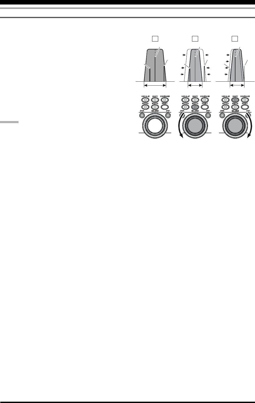
Page 62 FTDX5000 OPERATING MANUAL
I
NTERFERENCE
R
EJECTION
(S
IGNALS
WITHIN
3
KHZ
)
USING IF SHIFT AND WIDTH TOGETHER (SSB/CW/RTTY/PKT/AM MODES)
The IF Shift and Variable IF Width features, together, form a very effective interference-fighting filter system.
IF
BANDWIDTH
IF
BANDWIDTH
IF
BANDWIDTH
Desired Signal Desired Signal Desired Signal
QRM
QRMQRMQRM
QRMQRM
For example, in Figure “A” you can see how interference
has appeared both on the high and low sides of the desired
signal. By pressing the [WIDTH] button (the button will
glow red) and then rotating the [SELECT](width) knob,
as shown in Figure “B”, the interference from one side
can be eliminated, then press the [SHIFT] button to change
the function of the [SELECT] knob to the SHIFT knob
(the [SHIFT] button glows red. However, the IF Width
adjustment is not changed). Now, by re-positioning the
[SELECT](shift) knob (Figure “C”), the interference on
the opposite side can be removed, without re-introducing
the interference previously eliminated in Figure “B”.
ADVICE:
The Width and Shift features are the primary tools you
should use for best interference reduction. After narrow-
ing the bandwidth (width) and/or adjusting the center of
the passband (shift), the Contour control may also yield
further signal-enhancement benefits on the net residual
bandwidth. Additionally, the IF Notch Filter (see the next
section) may be utilized, in conjunction with the three other
filter systems, to significant advantage.
ABC
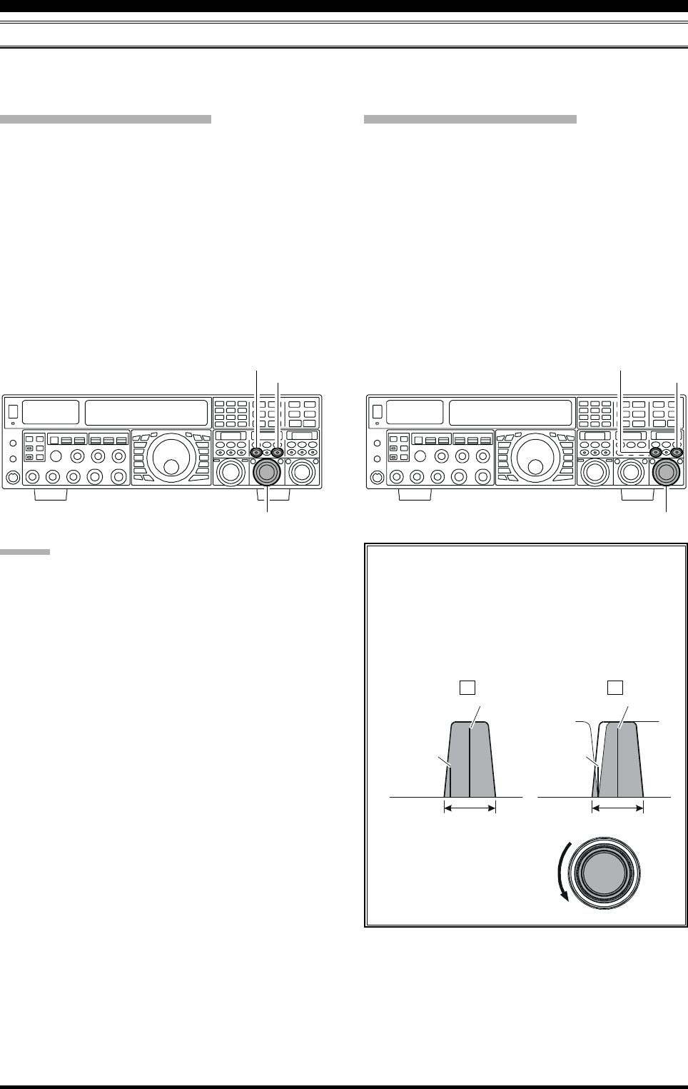
Page 63FTDX5000 OPERATING MANUAL
I
NTERFERENCE
R
EJECTION
(S
IGNALS
WITHIN
3
KHZ
)
IF NOTCH FILTER OPERATION (SSB/CW/RTTY/PKT/AM MODES)
The IF Notch filter is a highly effective system that allows you to slice out an interfering beat note or other carrier signal
from inside the receiver passband.
VFO-A IF Notch Operation
Press the (VFO-A)[NOTCH] button. The (VFO-
A)[NOTCH] button glows red, and the current “null”
(or “Peak”) position of the IF notch filter will appear
in the SUB DISPLAY-II window. The (VFO-
A)[SELECT] knob will now function as the notch
adjustment knob.
Rotate the (VFO-A)[SELECT] knob to adjust the cen-
ter frequency of the IF notch filter.
Press the (VFO-A)[CLEAR] button to move the “null”
position to center.
To switch the IF notch filter off, press the (VFO-
A)[NOTCH] button once more.
The affect of rotation of the [SELECT](notch)
knob on the performance of the IF notch filter is
depicted in Figure “A”. In Figure “B”, you can see
the notching effect of the IF notch filter as you ro-
tate the [SELECT](notch) knob to eliminate the
incoming interference.
VFO-B IF Notch Operation
Press the (VFO-B)[NOTCH] button. The (VFO-
B)[NOTCH] button glows red, and current “null” (or
“Peak”) position of the IF notch filter will be indicated
in the SUB DISPLAY-III window. The (VFO-
B)[SELECT] knob will now function as the notch
adjustment knob.
Rotate the (VFO-B)[SELECT] knob to adjust the cen-
ter frequency of the IF notch filter.
Press the (VFO-B)[CLEAR] button to move the “null”
position to center.
To switch the IF notch filter off, press the (VFO-
B)[NOTCH] button once more.
ADVICE:
The width of the IF notch null may be adjusted using
Menu item “110 RDSP NOTCH WI”. Both “Wide”
and “Narrow” selections are available, with “Narrow”
providing the least disruption of the “desired” signal.
You may select the display pattern shown in the SUB
DISPLAY window from three patterns via Menu item
“019 DISP SELECT”. See page 122 for details.
When the optional DMU-2000 Data Management Unit
is connected, the effect of the IF notch filter may be
observed using the Audio Scope (on the “Oscilloscope”
page). The notch will be seen as a “dip” in the noise
platform observed. What’s more, the “Waterfall” dis-
play may be used to observe the effect of the IF notch
filter, which will appear as a white area in the colored
background. The tuning rate for the IF notch is some-
what slow while you adjust the [SELECT](notch)
knob, so the use of the Waterfall display to confirm
proper adjustment is highly recommended.
(VFO-A)[SELECT] Knob
[CLEAR] Button
(VFO-A)[NOTCH] Button
(VFO-B)[SELECT] Knob
[CLEAR] Button
(VFO-B)[NOTCH] Button
IF
BANDWIDTH
QRM
(Heterodyne)
QRM
(Heterodyne)
IF
BANDWIDTH
Desired Signal Desired Signal
AB
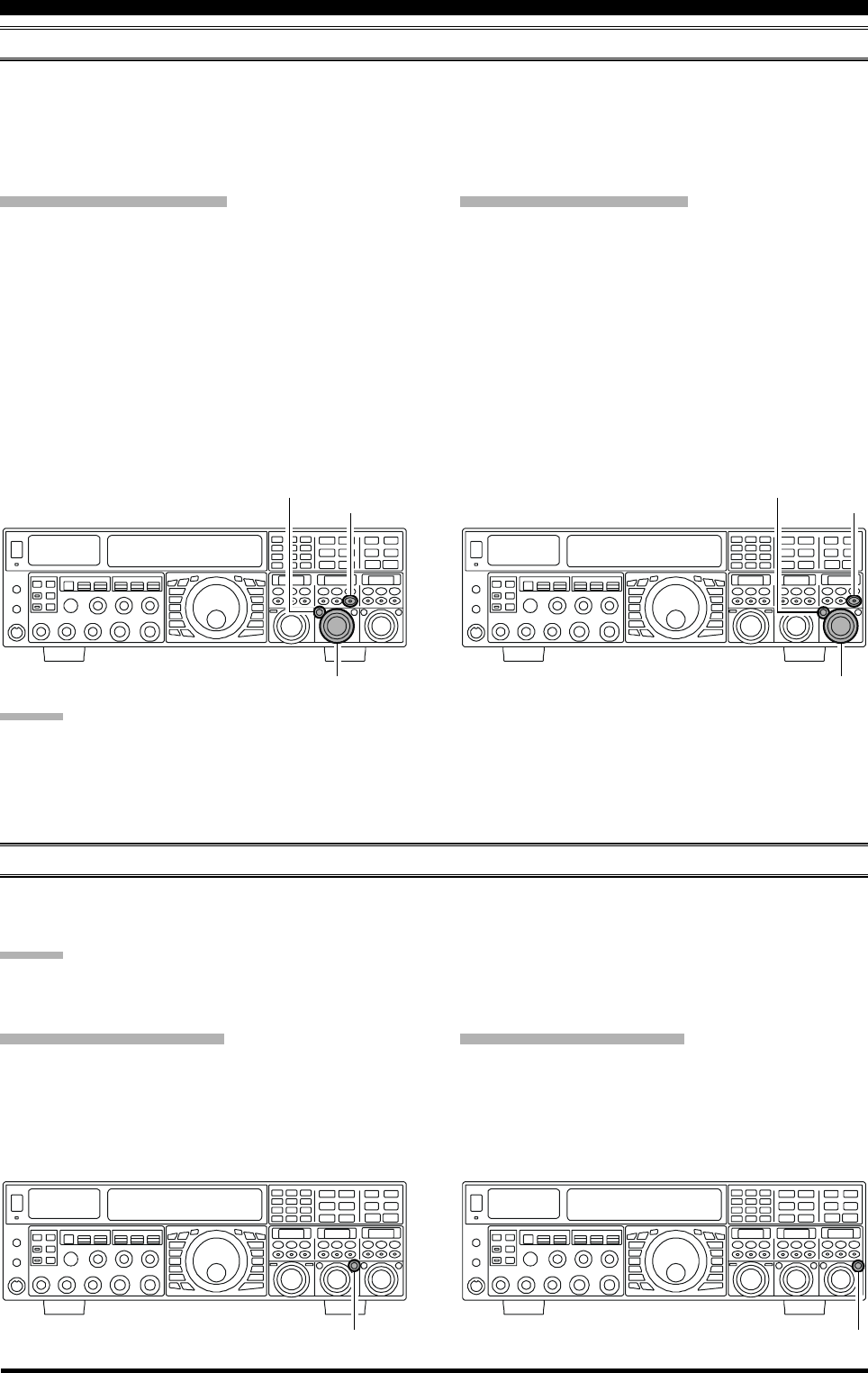
Page 64 FTDX5000 OPERATING MANUAL
DIGITAL NOISE REDUCTION (DNR) OPERATION
The Digital Noise Reduction (DNR) system is designed to reduce the level of random noise found on the HF and 50 MHz
bands. It is especially effective during SSB operation. By rotating the [DNR] knob, any of 15 different noise-reduction
algorithms can be selected; each of these algorithms was created for dealing with a different noise profile, and you will want
to experiment with the DNR system to find the best setting according to the noise currently being experienced.
I
NTERFERENCE
R
EJECTION
(S
IGNALS
WITHIN
3
KHZ
)
VFO-A DNR Operation
Press the (VFO-A)[DNR] button. The button will glow
red, and the current noise-reduction algorithm will ap-
pear in the SUB DISPLAY-II window. The (VFO-
A)[SELECT] knob will now function as the notch
adjustment knob.
Rotate the (VFO-A)[SELECT] knob to select the set-
ting that most effectively reduces the noise level.
Press the (VFO-A)[CLEAR] button to set the noise-
reduction algorithm to default.
To switch the DNR system off, press the (VFO-
A)[NOTCH] button once more.
DIGITAL NOTCH FILTER (DNF) OPERATION
The Digital Notch Filter (DNF) is an effective beat-canceling filter that can null out a number of interfering beat notes
inside the receiver passband. Because this is an Auto-Notch feature, there is no adjustment knob associated with this filter.
ADVICE:
If a very strong interfering carrier is encountered, we recommend you first use the IF notch filter, as it is the most effective
notching tool in the receiver section.
VFO-A DNF Operation
Press the (VFO-A)[DNF] button. The button glows red,
confirming that the DNF system is engaged.
To switch the DNF system off, press the (VFO-
A)[DNF] button once more.
VFO-B DNR Operation
Press the (VFO-B)[DNR] button. The (VFO-B)[DNR]
button glows red, and the current noise-reduction al-
gorithm will appear in the SUB DISPLAY-II window.
The (VFO-B)[SELECT] knob will now function as
the notch adjustment knob.
Rotate the (VFO-B)[SELECT] knob to select the set-
ting that most effectively reduces the noise level.
Press the (VFO-B)[CLEAR] button to set the noise-
reduction algorithm to default.
To switch the DNR system off, press the (VFO-
B)[NOTCH] button once more.
(VFO-A)[SELECT] Knob (VFO-B)[SELECT] Knob
(VFO-B)[DNR] Button
[CLEAR] Button
(VFO-A)[DNR] Button
[CLEAR] Button
(VFO-A)[DNF] Button (VFO-B)[DNF] Button
VFO-A DNF Operation
Press the (VFO-B)[DNF] button. The button glows
red, confirming that the DNF system is engaged.
To switch the DNF system off, press the (VFO-
B)[DNF] button once more.
ADVICE:
You may select the display pattern shown in the SUB DIS-
PLAY window from three patterns via Menu item “019
DISP SELECT”. See page 122 for details.
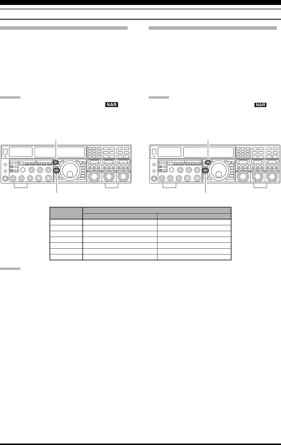
Page 65FTDX5000 OPERATING MANUAL
I
NTERFERENCE
R
EJECTION
(S
IGNALS
WITHIN
3
KHZ
)
NARROW (NAR) ONE-TOUCH IF FILTER SELECTION
VFO-B “One-Touch Narrow” Operation
Press the [B] button (the button glows orange).
Pressing the [NAR] button engages a narrow IF DSP
filter, specific to the mode in use, and not related to the
setting of the [WIDTH] knob.
Pressing the [NAR] button once more returns band-
width control to the Width/Shift system. The factory
default settings of the bandwidth are as shown in the
table below.
ADVICE:
When the narrow bandwidth is selected, the “ ” icon
will appear in the display, and the bandwidth on the SUB
DISPLAY-III will be reduced, (if the SUB DISPLAY-III
window indicates the bandwidth).
VFO-A “One-Touch Narrow” Operation
Press the [A] button to activate VFO-A (the button will
glow red).
Pressing the [NAR] button engages a narrow IF DSP
filter, specific to the mode in use, and not related to the
setting of the [WIDTH] knob.
Pressing the [NAR] button once more returns the band-
width control to the Width/Shift system. The factory
default of the bandwidth is as shown below.
ADVICE:
When the narrow bandwidth is selected, the “ ” icon
will appear in the display, and the bandwidth depiction in
the SUB DISPLAY-II window will be narrowed (if SUB
DISPLAY-II window is showing the bandwidth).
[A] Button [B] Button
[NAR] Button [NAR] Button
OFF
2.4 kHz (1.8 kHz - 4.0 kHz / 16 steps)
2.4 kHz (500 Hz - 2.4 kHz / 7 steps)
500 Hz (500 Hz - 2.4 kHz / 7 steps)
500 Hz (500 Hz - 2.4 kHz / 7 steps)
25 kHz (±5.0 kHz Deviation)
9 kHz
25 kHz (±5.0 kHz Deviation)
ON
1.8 kHz (200 Hz - 1.8 kHz / 9 steps)
500 Hz (50 Hz - 500 Hz / 10 steps)
300 Hz (50 Hz - 500 Hz / 10 steps)
300 Hz (50 Hz - 500 Hz / 10 steps)
12.5 kHz (±2.5 kHz Deviation)
6 kHz
12.5 kHz (±2.5 kHz Deviation)
MODE
LSB/USB
CW
RTTY(LSB)
PKT(LSB/USB)
PKT(FM)
AM
FM
NAR BUTTON
ADVICE:
You may select the display pattern shown in the SUB DIS-
PLAY window from three patterns via Menu item “019
DISP SELECT”. See page 122 for details.
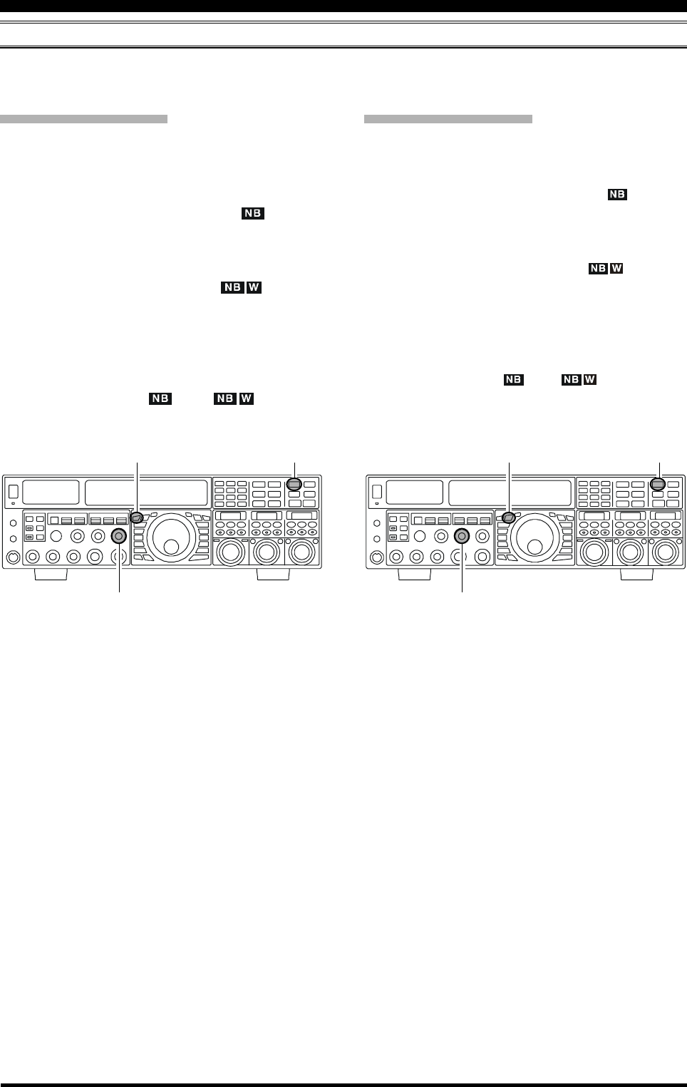
Page 66 FTDX5000 OPERATING MANUAL
IF NOISE BLANKER (NB) OPERATION
The FTDX5000 includes an effective IF Noise Blanker, which can significantly reduce pulse noise like that caused by
automotive ignition systems.
VFO-A NB Operation
Press the [A] button (the button glows red), if needed
to enable VFO-A.
Press the [NB] button briefly to reduce short duration
pulse noise such as from switching transients, auto-
mobile ignitions and power lines. The “ ” icon will
appear in the display to confirm that the Narrow-NB is
operating.
Press the [NB] button again to reduce longer-dura-
tion man-made pulse noise. The “ ” icon will
blink for three seconds, and thereafter will appear con-
tinuously, to confirm that the Wide-NB is operating.
Rotate the (VFO-A)[NB] knob to the point where the
offending noise is best reduced or eliminated.
To end Noise Blanker operation, press the [NB] but-
ton once more. The “ ” (or “ ”) icon will
turn off, confirming that the Noise Blanker is no longer
in operation.
I
NTERFERENCE
R
EJECTION
(S
IGNALS
WITHIN
3
KHZ
)
VFO-B NB Operation
Press the [B] button (the [B] button glows orange).
Press the [NB] button briefly to reduce short duration
pulse noise such as from switching transients, auto-
mobile ignitions and power lines. The “ ” icon will
appear in the display to confirm that the Narrow-NB is
operating.
Press the [NB] button again to reduce longer-dura-
tion man-made pulse noise. The “ ” icon will
blink for three seconds, and thereafter will appear con-
tinuously, to confirm that the Wide-NB is operating.
Rotate the (VFO-B)[NB] knob to the point where the
offending noise is best reduced or eliminated.
To end Noise Blanker operation, press the [NB] but-
ton once more. The “ ” (or “ ”) icon will turn
off, confirming that the Noise Blanker is no longer in
operation.
[A] Button [NB] Knob [B] Button [NB] Knob
(VFO-A)[NB] Knob (VFO-B)[NB] Knob
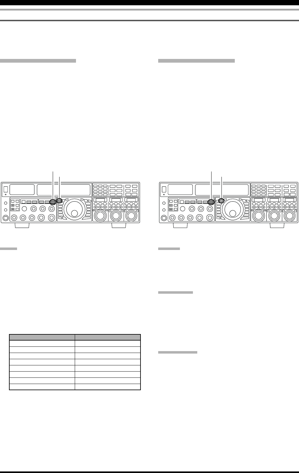
Page 67FTDX5000 OPERATING MANUAL
AGC (AUTOMATIC GAIN CONTROL)
The AGC system is designed to help compensate for fading and other propagation effects, with characteristics that can be
of particular value on each operating mode. The basic objective of AGC is to maintain a constant audio output level once
a certain minimum threshold of signal strength is achieved.
VFO-A AGC Selection
Press the [A] button briefly to enable VFO-A (the LED
in the [A] button will glow red).
Move the [AGC] knob up or down to set the desired
receiver recovery time constant of the VFO-A receiver.
The selected recovery time will be indicated in the AGC
column of the Block Diagram Display.
Hold the [AGC] knob up or down for two seconds to
disable the AGC (for testing or weak-signal reception).
For most operations, we recommend using the “AUTO”
mode by pressing the [AGC] knob in briefly, or mov-
ing the [AGC] knob to set the ATT display to the
“AUTO” position.
VFO-B AGC Selection
Press the [B] button (the [B] button glows orange).
Move the [AGC] knob up and down to set the desired
receiver recovery time constant of the VFO-A receiver.
The selected recovery time will be indicated in the AGC
column of the Block Diagram Display.
Hold the [AGC] knob up or down for two seconds to
disable the AGC (for testing or weak-signal reception).
For most operations, we recommend using the “AUTO”
mode by pressing the [AGC] knob in briefly, or mov-
ing the [AGC] knob to set the ATT display to the
“AUTO” position.
T
OOLS
FOR
C
OMFORTABLE
AND
E
FFECTIVE
R
ECEPTION
NOTE:
When the AGC receiver recovery time is set to “OFF”,
the S-meter will no longer deflect. Additionally, you
will likely encounter distortion on stronger signals, as
the IF amplifiers and the following stages are prob-
ably being overloaded.
Normally, the AGC “AUTO” selection is satisfactory
for most situations, but in the event of operation on a
crowded band where you wish to receive a weak sig-
nal, you may change the setting (to “FAST”, for ex-
ample). The AGC “AUTO” mode selections are:
[A] Button
[AGC] Knob
[B] Button
[AGC] Knob
ADVICE:
When a received signal becomes degraded due to pulse
type noise, you may improve signal readability by setting
Menu items “002 AGC FST HLD”, “004 AGC MID
HLD”, and “006 AGC SLW HLD” to “0 msec”.
QUICK POINT
Several aspects of AGC performance may be configured
via the Menu. However, because AGC can have such a
profound impact on overall receiver performance, we gen-
erally do not recommend any changes to the AGC Menu
selections until you are thoroughly familiar with the per-
formance of the FTDX5000.
TERMINOLOGY:
Automatic Gain Control, or AGC, is a circuit that senses
the incoming signal strength, and then limits the gains of
the RF and IF stages, to maintain the output audio volume
at a more-or-less constant level. AGC also protects the
RF, IF, Audio, and DSP stages from overload, by limiting
the signal strength applied to circuits, regardless of the
input signal level.
OPERATING MODE
LSB
USB
CW
AM
FM
RTTY
PKT (FM)
PKT (LSB)
AUTO AGC SELECTION
SLOW
SLOW
FAST
FAST
FAST
SLOW
FAST
SLOW
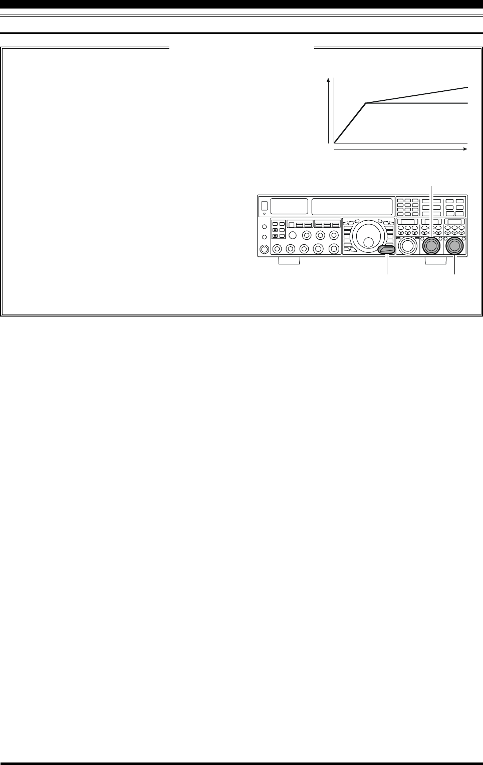
Page 68 FTDX5000 OPERATING MANUAL
T
OOLS
FOR
C
OMFORTABLE
AND
E
FFECTIVE
R
ECEPTION
AGC (AUTOMATIC GAIN CONTROL)
SLOPED AGC Operation
In traditional AGC systems, the audio output from the transceiver becomes essentially constant, once the threshold
for AGC action is reached (usually several dozen dB above the no-signal
noise floor). The FTDX5000, however, includes an innovative Sloped AGC
system on the VFO-A receiver that allows the audio volume to rise and fall
slightly according to signal strength. Although the rise/fall slope is not dra-
matic, it is sufficient to allow you to use your ear to discern and separate
signals according to signal strength, not just audio frequency.
NORMAL
Input Signal
Audio Output
SLOPED
Using Sloped AGC
1. Press the [MENU] button briefly to enter the Menu
mode.
2. Use the (VFO-A)[SELECT] knob to select Menu
item “107 ROUT AGC SLP”.
3. Rotate the (VFO-B)[SELECT] knob to change the
setting to “SLOPE”.
4. Press and hold in the [MENU] button for two sec-
onds to save the new setting and exit to normal op-
eration. You will now be using the Sloped AGC
system.
(VFO-B)[SELECT] Knob
[MENU] Button
(VFO-A)[SELECT] Knob
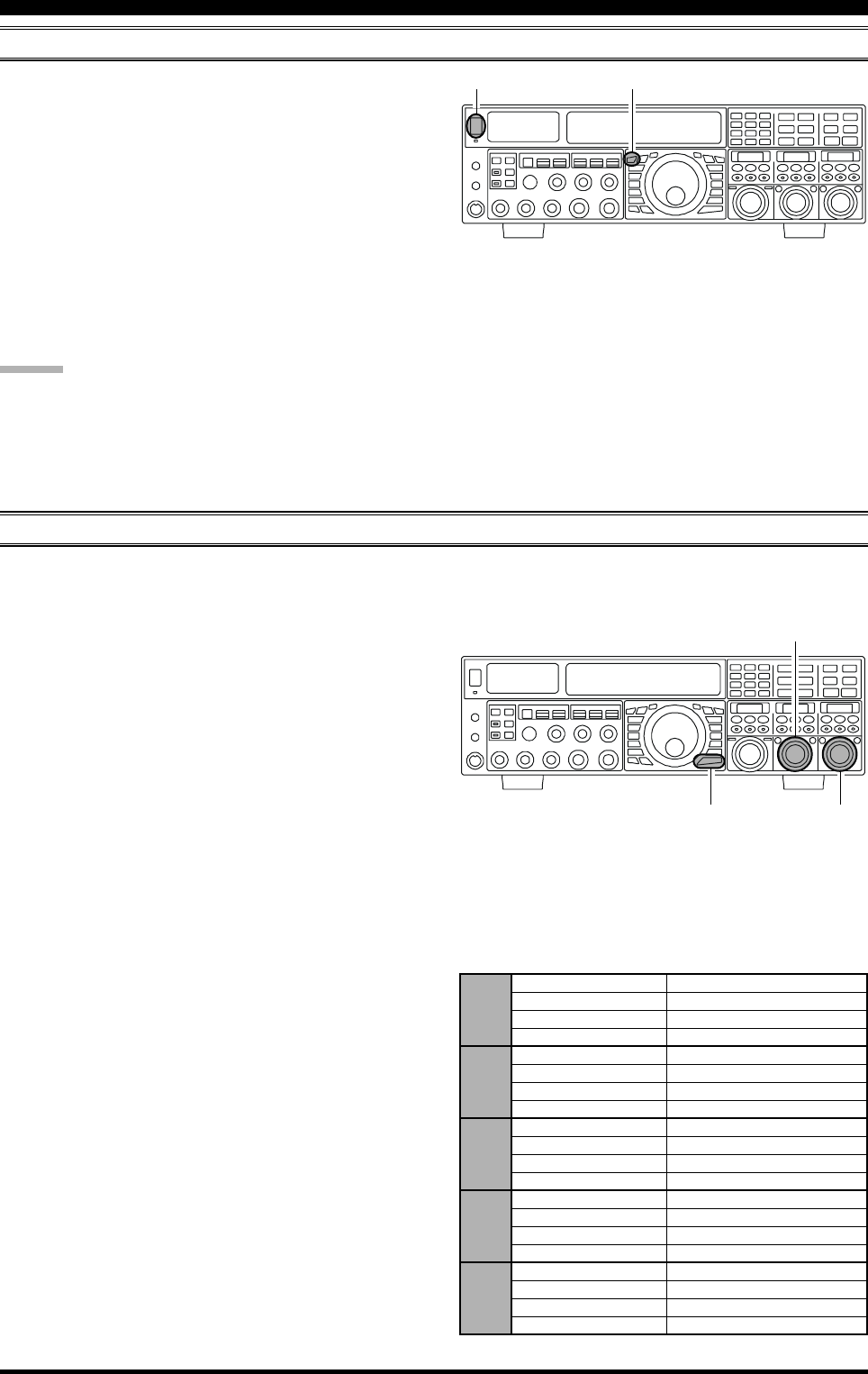
Page 69FTDX5000 OPERATING MANUAL
MUTE FEATURE (VFO-A BAND)
T
OOLS
FOR
C
OMFORTABLE
AND
E
FFECTIVE
R
ECEPTION
There may be occasions during Dual Receive operation
when you want to silence the VFO-A receiver temporarily,
to concentrate on the signal being received on the VFO-B
receiver. The Mute feature makes this simple to accom-
plish.
Press the (VFO-A)[RX] button briefly, located to the up-
per left of the Main Tuning Dial knob. The VFO-A re-
ceiver will be silenced, and the green LED in the (VFO-
A)[RX] button will blink.
To restore reception on the VFO-A receiver, just press the
blinking (VFO-A)[RX] button once more.
ADVICE:
If you press the [POWER] switch briefly while the trans-
ceiver is turned on, the transceiver audio will be muted for
three seconds.
[A] Button
[POWER] Switch
ADJUSTABLE RECEIVER AUDIO FILTER
The FTDX5000 includes a adjustable receiver audio filter, that provides precise, independent control of the low- and upper-
ranges.
1. Press the [MENU] button briefly, to enter the Menu
mode.
2. Rotate the (VFO-A)[SELECT] knob to find Menu
items “047” through “050”; these parameters apply to
the adjustment of the receiver audio filter in the AM
mode, Menu items “053” through “056” apply to the
adjustment of the RX audio filter in the CW mode,
Menu items “075” through “078” apply to the adjust-
ment of the RX audio filter in the FM mode, Menu
items “089” through “092” apply to the adjustment of
the RX audio filter in the RTTY mode, and Menu items
“099” through “102” apply to the adjustment of the
RX audio filter in the SSB mode.
3. Rotate the (VFO-B)[SELECT] knob to perform ad-
justments to a particular Menu item.
You may confirm the change of the sound quality from
the speaker or headphones.
4. When you have completed all adjustments, press and
hold in the [MENU] button for two seconds to save
the new settings and exit to normal operation. If you
only press the [MENU] button momentarily to exit,
any changes you performed will not be stored.
AM 047 A3E LCUT FRQ OFF / 100 (Hz) ~ 1000 (Hz)
048 A3E LCUT SLP 6dB/oct or 18dB/oct
049 A3E HCUT FRQ 700 (Hz) ~ 4000 (Hz) / OFF
050 A3E HCUT SLP 6dB/oct or 18dB/oct
CW 053 A1A LCUT FRQ OFF / 100 (Hz) ~ 1000 (Hz)
054 A1A LCUT SLP 6dB/oct or 18dB/oct
055 A1A HCUT FRQ 700 (Hz) ~ 4000 (Hz) / OFF
056 A1A HCUT SLP 6dB/oct or 18dB/oct
FM 075 F3E LCUT FRQ OFF / 100 (Hz) ~ 1000 (Hz)
076 F3E LCUT SLP 6dB/oct or 18dB/oct
077 F3E HCUT FRQ 700 (Hz) ~ 4000 (Hz) / OFF
078 F3E HCUT SLP 6dB/oct or 18dB/oct
RTTY 089 RTTY LCUT FRQ OFF / 100 (Hz) ~ 1000 (Hz)
090 RTTY LCUT SLP 6dB/oct or 18dB/oct
091 RTTY HCUT FRQ 700 (Hz) ~ 4000 (Hz) / OFF
092 RTTY HCUT SLP 6dB/oct or 18dB/oct
SSB 099 A3J LCUT FRQ OFF / 100 (Hz) ~ 1000 (Hz)
100 A3J LCUT SLP 6dB/oct or 18dB/oct
101 A3J HCUT FRQ 700 (Hz) ~ 4000 (Hz) / OFF
102 A3J HCUT SLP 6dB/oct or 18dB/oct
(VFO-B)[SELECT] Knob
[MENU] Button
(VFO-A)[SELECT] Knob
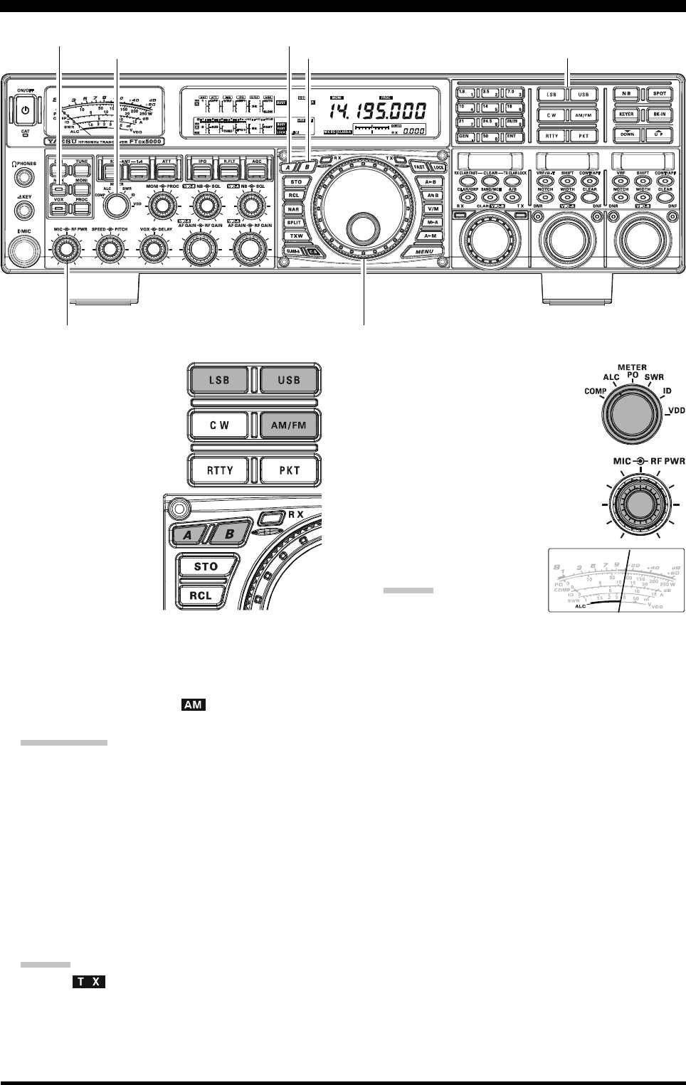
Page 70 FTDX5000 OPERATING MANUAL
1. The operating mode is se-
lected using the [MODE]
buttons. The VFO (A or B)
to which the selection is ap-
plied is selected by the [A]
or [B] button located to the
upper left of the Main
Tuning Dial knob. Usu-
ally, the [A] button
glows red, signifying
that VFO-A is being ad-
justed. Similarly, press-
ing the [B] button will
cause the [B] button to
glow orange, signifying VFO-B adjustment. Press the
[A] or [B] button to select the desired VFO. Then press
the [LSB] or [USB] button briefly to select one of the
SSB modes. For AM operation, press the [AM/FM]
button repeatedly until the “ ” icon appears in the
display.
QUICK POINT:
By convention, LSB is used in the 7 MHz and lower
Amateur bands for SSB communication, and USB is
used on the 14 MHz and higher bands (the 10 MHz
band is used for CW and data modes only).
2. Rotate the Main Tuning Dial knob to adjust the oper-
ating frequency. Alternatively, you may use the [UP]/
[DWN] scanning buttons on the MH-31B8 Hand Mi-
crophone to sweep up or down the current band.
3. Press the microphone’s PTT (Push To Talk) switch to
begin transmission; speak into the microphone in a
normal voice level.
ADVICE:
The “ ” indicator will light up in the frequency
display area, confirming that transmission is in
progress.
When transmitting in the AM mode, rotate the [RF
PWR] knob to set a maximum (carrier) power out-
put of 50 Watts.
4. In the SSB mode, adjust the micro-
phone amplifier gain to match the
microphone and your voice level.
set the [METER] switch to the
“ALC” position and close the PTT
switch. Speak into the microphone in
a normal voice level, and adjust the
[MIC] (gain) knob so that the ALC
voltage stays within the blue ALC
zone of the meter (up to 2/3 of full
scale deflection) on voice
peaks.
ADVICE:
The microphone gain of
the AM mode has been programmed at the factory
to a level that should be satisfactory for most situ-
ations. However, using Menu item “051 A3E MIC
GAIN”, you may set a different fixed value, or
choose the “MCVR” option, which then lets you
use the front panel [MIC] knob to set the micro-
phone gain in the AM mode. In this case, the [MIC]
knob should not be advanced to the point where
the ALC meter deflects. In many cases, the same
setting used on SSB will be satisfactory.
The relative Microphone Gain level will show for
3 seconds in the lower right corner of the Main
Display whenever the inner [MIC] knob is turned.
Alternately, the 3-second display feature may be
changed to show in the SUB DISPLAY-
III
win-
dow via Menu item “018 DISP INDI”. Addition-
ally, you may disable the 3-second display feature
via Menu item “017 DISP LVL IND” See page
122 for details.
5. Release the PTT switch at the end of your transmis-
sion. The transceiver will return to the receive mode.
SSB/AM MODE TRANSMISSION
Main Tuning Dial knob
[METER] Switch [B] Button
[MOX] Button
[MODE] Buttons
[MIC] Knob
[RF PWR] Knob
[A] Button

Page 71FTDX5000 OPERATING MANUAL
SSB/AM MODE TRANSMISSION
ADVICE:
ALC meter deflection may be caused by excessive drive
power, and also by reflected power detected in the an-
tenna system. If the impedance presented to the trans-
ceiver is other than 50 Ohms, the ALC meter action
observed may not be related to the proper setting of
the [MIC] (gain) knob. Therefore, we recommend that
you make [MIC] gain adjustments into a dummy load
or an antenna system presenting an impedance very
close to 50 Ohms.
Rotate the [RF PWR] knob to set the desired power
output. Clockwise rotation of the [RF PWR] knob will
increase the power. The adjustment
range is between 10 Watts and 200
Watts, and you should always use the
minimum power necessary for main-
taining reliable communications.
The RF Power Output will show for 3 seconds in the
lower right corner of the Main Display whenever the
outer [RF PWR] knob is turned.
Alternately, the 3-second display feature may be
changed to show in the SUB DISPLAY-
III
window
via Menu item “018 DISP INDI”. Additionally, you
may disable the 3-second display feature via Menu item
“017 DISP LVL IND” See page 122 for details.
The analog PO meter indicates the average power out-
put level. SSB transmit average talk power is normally
10% to 50% of the peak power output. Voice charac-
teristics, microphone qualities, parametric equalizer
and compression settings affect actual talk power out-
put.
When performing transmitter tests for setup of the
[MIC] or [RF PWR] knobs, be sure to monitor the
frequency before transmitting, to avoid interference to
others who may already be using the frequency.
Four techniques for initiating Transmit/Receive con-
trol are provided on the FTDX5000. You may choose
the technique(s) that best suit your operating needs:
Pressing the microphone PTT switch will engage
the transmitter.
The rear panel PTT jack may be connected to a
foot switch or other manual switching device in
order to engage the transmitter.
Pressing the front panel [MOX] button will lock
the transmitter on. Press the [MOX] button again
to return to receive.
The VOX (Voice Operated Xmit) circuit will en-
gage the transmitter automatically when you speak
into the microphone. For VOX operation details,
see page 81.
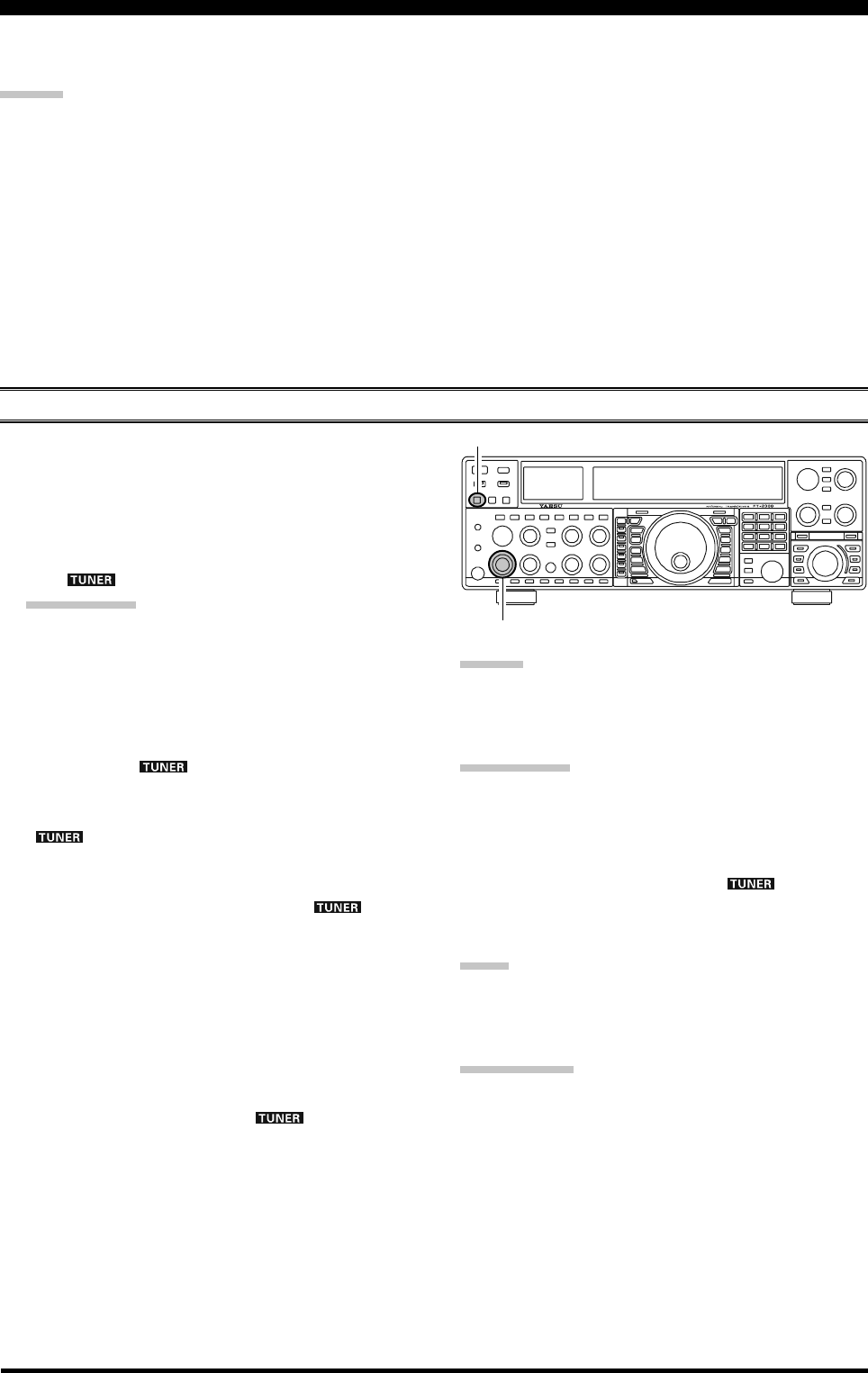
Page 72 FTDX5000 OPERATING MANUAL
The Automatic Antenna Tuner (“ATU”) built into each FTDX5000 is crafted to ensure a 50-Ohm load for the final amplifier
stage of the transmitter. We recommend the ATU be used whenever you operate the FTDX5000.
ADVICE:
The ATU of the FTDX5000, being located inside the station, only adjusts the impedance presented to the transmitter at
the station end of your coaxial cable feedline. It does not “tune” the SWR at the antenna feedpoint itself. When design-
ing and building your antenna system, we recommend that every effort be made to ensure a low SWR at the antenna
feedpoint.
The ATU of the FTDX5000 includes 100 memories for tuning data. Eleven of these memories are allocated, one per
Amateur band, so that each band has at least one setting preset for use on that band. The remaining 89 memories are
reserved for the 89 most-recent tuning points, allowing quick frequency change without the need to retune the ATU.
The ATU in the FTDX5000 is designed to match impedances within the range of 16.5 Ohms to 150 Ohms, correspond-
ing to an SWR of 3:1 or less on the HF amateur bands (6 meter amateur band: 25 Ohms to 100 Ohms, corresponding to
an SWR of 2:1 or less). Accordingly, simple non-resonant whip antennas, along with random-length wires and the
“G5RV” antenna (on most bands) may not be within the impedance matching range of the ATU.
ATU OPERATION
USING THE AUTOMATIC ANTENNA TUNER
1. Rotate the [RF PWR] knob fully clockwise (to the
right).
2. Use the Main Tuning Dial knob to set the radio to the
desired operating frequency within the Amateur band.
3. Press the [TUNE] button briefly to place the ATU in
the transmit line (no adjustment/tuning will occur yet).
The “ ” icon will appear in the display.
QUICK POINT:
The brief press of the [TUNE] button will turn the tuner
on, and the microprocessor will automatically select
the tuning point closest to the current operating fre-
quency.
4. Press and hold in the [TUNE] button for two seconds
to begin automatic tuning. The transmitter will be en-
gaged, and the “ ” icon will blink while tuning is
in progress. When the optimum tuning point has been
reached, the radio will return to receive, and the
“” icon will again glow steadily (instead of
blinking).
5. While tuning around the band using the Main Tuning
Dial knob, you will observe that the “ ” icon
blinks momentarily every 10 kHz. This momentary
blinking indicates that a new tuning window has been
entered. If you want to save tuning data associated with
each 10 kHz window, repeat step 4 (above) for each of
the windows. On bands like 1.8 MHz where the im-
pedance may change rapidly, the storage of a number
of tuning points is recommended.
6. To disconnect the ATU from the transmit line, press
the [TUNE] button briefly. The “ ” icon will turn
off, confirming that the ATU has been turned off. In
the “Off” mode, the transceiver will be directly con-
nected to the coaxial cable connected to your antenna,
and it will operate based on whatever impedance is
present at the station end of the coax.
ADVICE:
The ATU circuit is located between the final amplifier and
the rear-panel antenna jack; reception is not affected by
the ATU.
QUICK POINT:
As shipped from the factory, only one ATU alignment
point is saved on each Amateur band. This was memo-
rized during the final alignment and performance veri-
fication stages on the production line.
The momentary flickering of the “ ” icon occurs
whenever you cross over into a new 10 kHz ATU
memory window.
NOTE:
Please check the operating frequency before beginning the
tuning process, to be sure you are not interfering with oth-
ers who may already be using the frequency.
TERMINOLOGY:
Antenna Tuner Memories: The microprocessor of the ATU
makes a note of the positions of the tuning capacitors and
the selected inductors, and stores the data for each 10 kHz
window in which tuning has occurred. This eliminates the
need to re-tune every time you return to a frequency on
which you already have completed the tuning process.
[TUNE] Button
[RF PWR] Knob
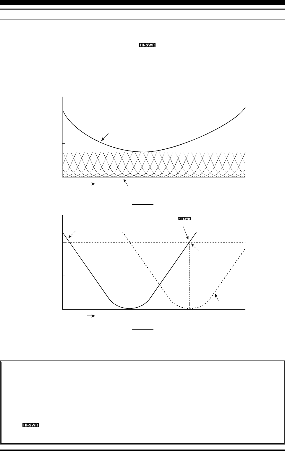
Page 73FTDX5000 OPERATING MANUAL
ABOUT ATU OPERATION
Figure 1 depicts a situation where normal tuning of the ATU has been successfully completed, and the tuning data has been
stored in the ATU memory. The antenna system as seen by the transmitter is shown.
In Figure 2, the operator has changed frequency, and the “ ” icon is shown. The operator presses and holds in the
[TUNE] button for two seconds to begin impedance matching using the ATU.
If a high SWR condition exists (above 3:1), corrective action must be taken in the antenna system to bring the impedance
closer to 50 Ohms. The ATU will refuse to memorize settings on frequencies where the SWR exceeds 3:1. The high SWR
may indicate a mechanical failure in the antenna or feed system, and such failures can lead to the generation of spurious
signals causing TVI, etc.
About ATU Memories
SWR (Post-tuning) Less than 1.5:1
The tuning settings are committed to the ATU memory.
SWR (Post-tuning) Greater than 1.5:1
Tuning data will not be retained in memory. If you return to the same frequency, the tuning process must be repeated.
SWR (Post-tuning) Greater than 3:1
The “ ” icon will light up, and tuning settings, if achieved, will not be memorized. Please investigate and
resolve the high SWR condition before attempting further operation using this antenna.
USING THE AUTOMATIC ANTENNA TUNER
SWR: 2.0
Frequency
SWR: 1.5
Feed Point SWR
SWR after ATU Tuning
SWR: 1.0
FIGURE 1
FIGURE 2
SWR: 3.0
SWR: 3.0
Frequency
SWR: 2.0
Memorized ATU Tuning
Retuned Setting
SWR: 1.0
The “ ” icon appears on the display
when you transmit on this frequency