Yaesu Musen 20415X20 AMATEUR RADIO WITH SCANNING RECEIVER User Manual pmd
Yaesu Musen Co., Ltd. AMATEUR RADIO WITH SCANNING RECEIVER pmd
UserManual.wiki
>
Yaesu Musen
>
20415X20 User Manual
Users Manual
Navigation menu
Upload a User Manual
Namespaces
Wiki Guide
HTML
PDF
Info
Views
User Manual
Discussion / Help
Navigation
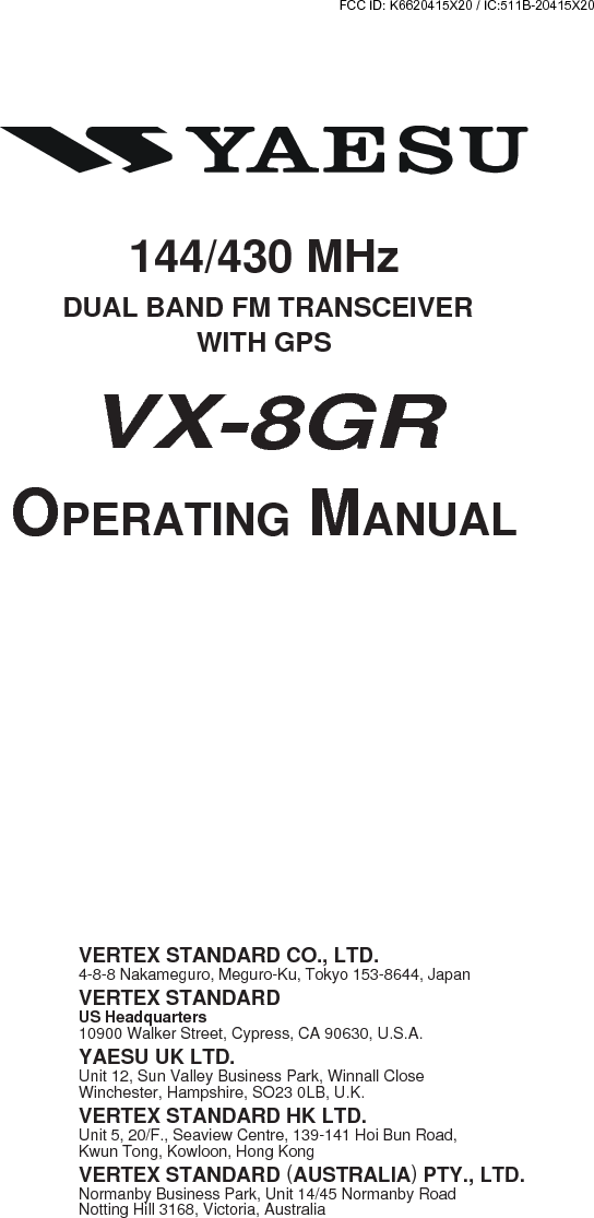
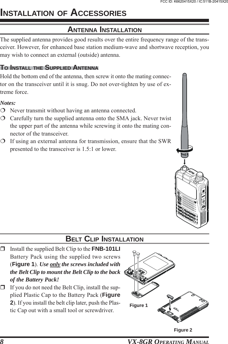
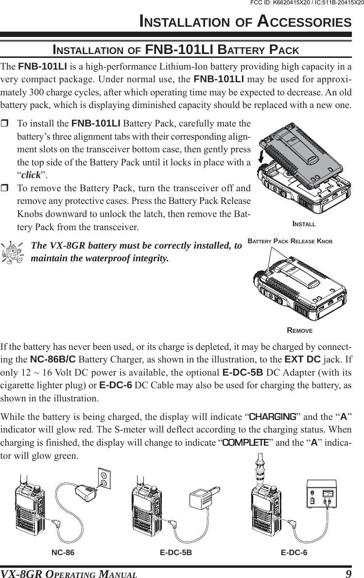
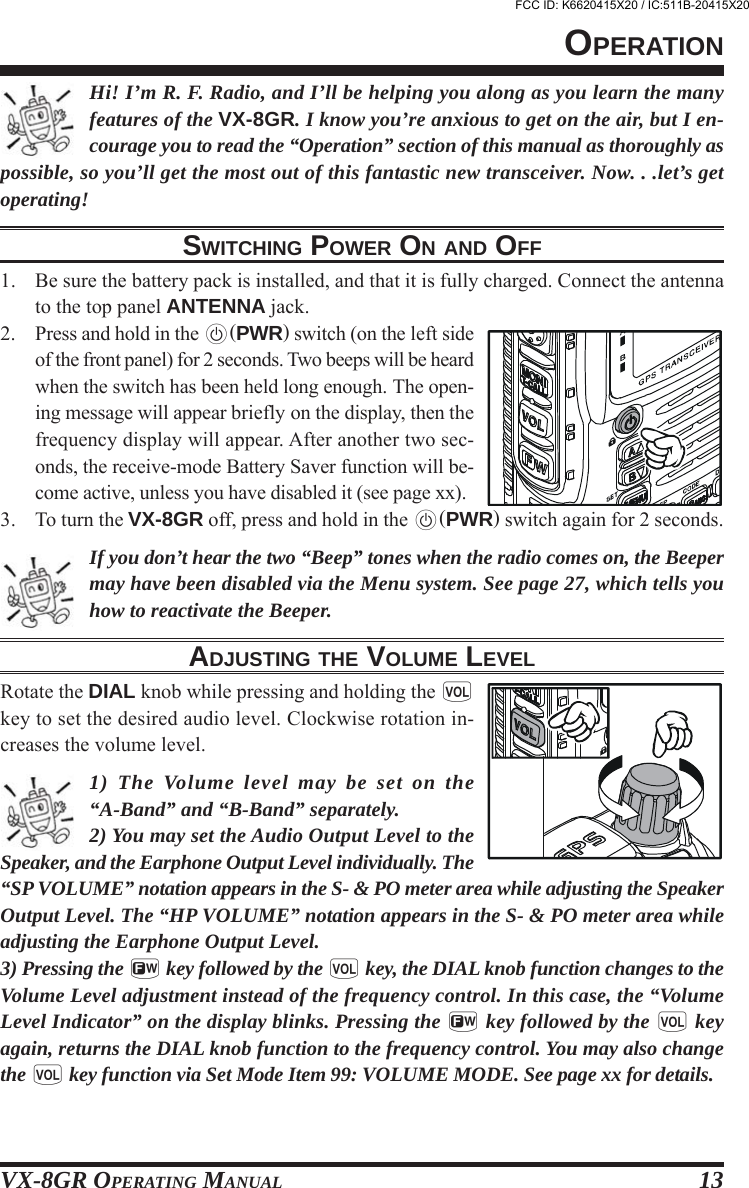
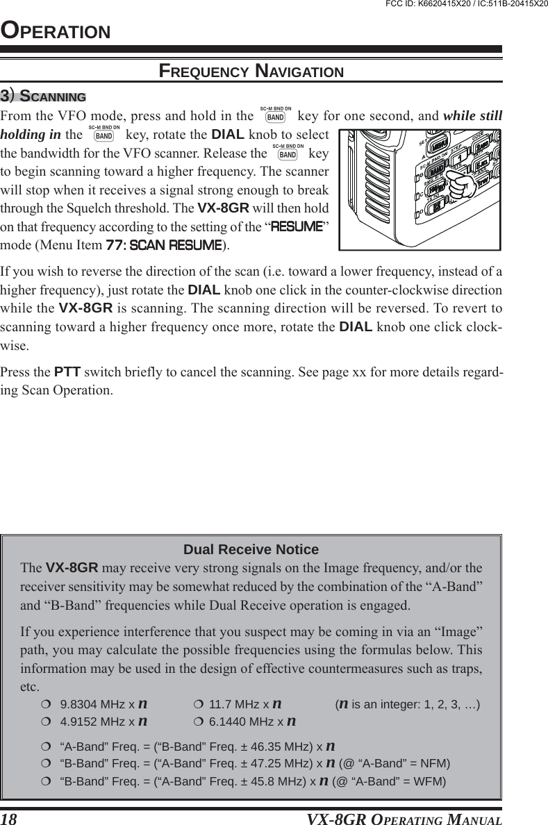
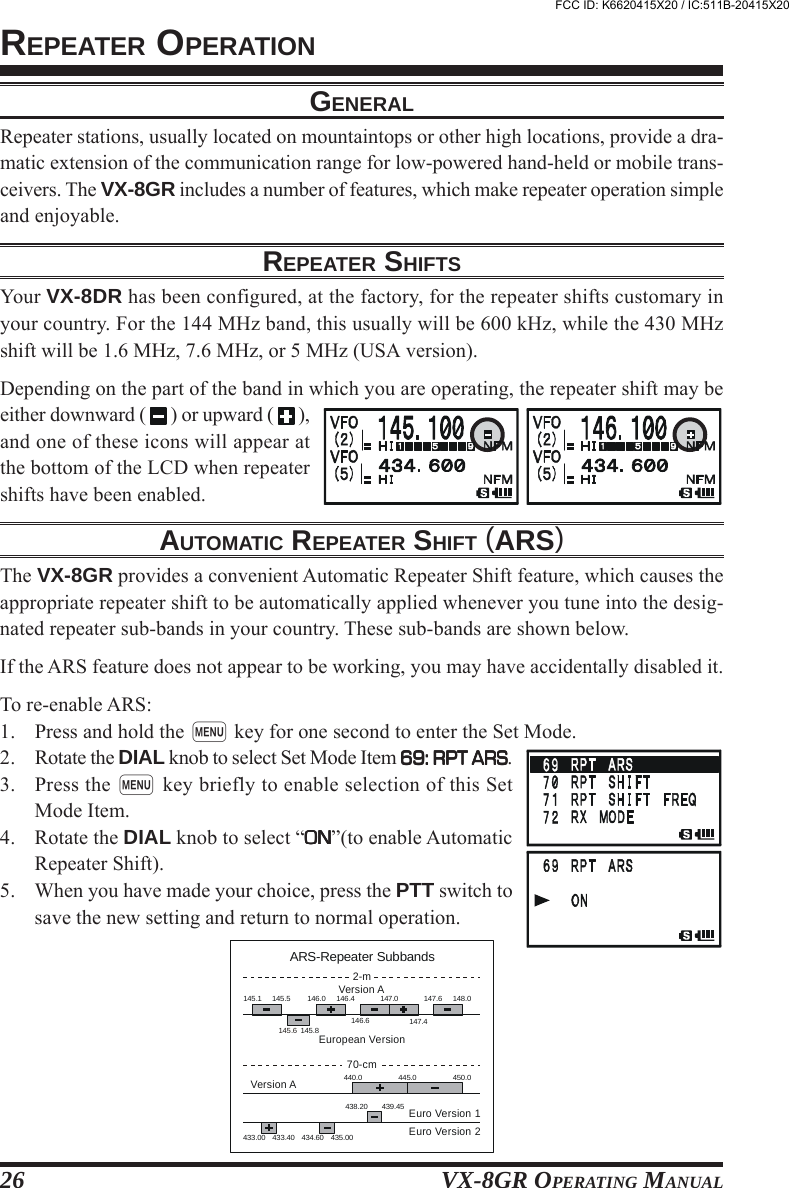
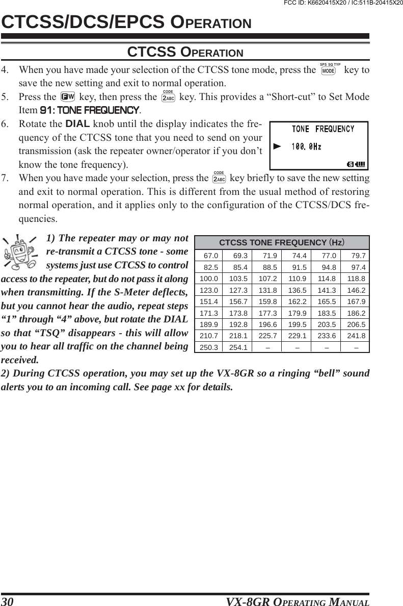
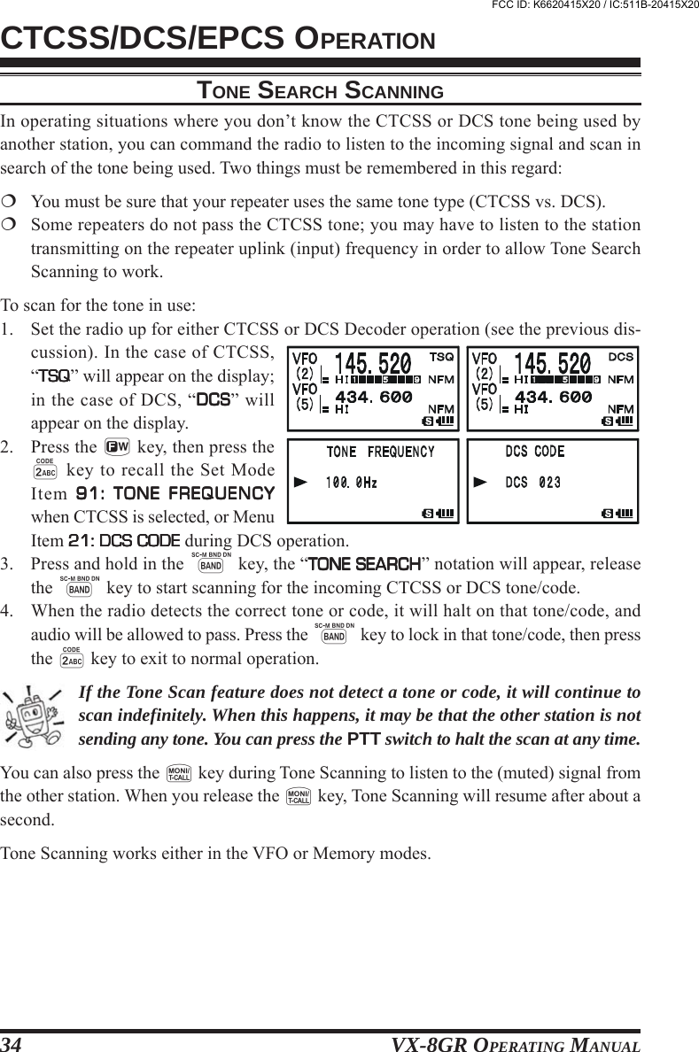
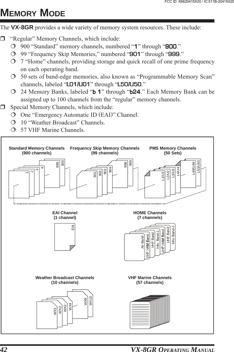
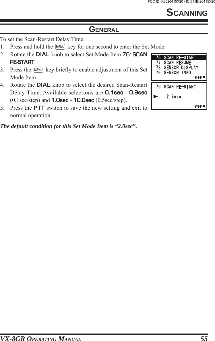
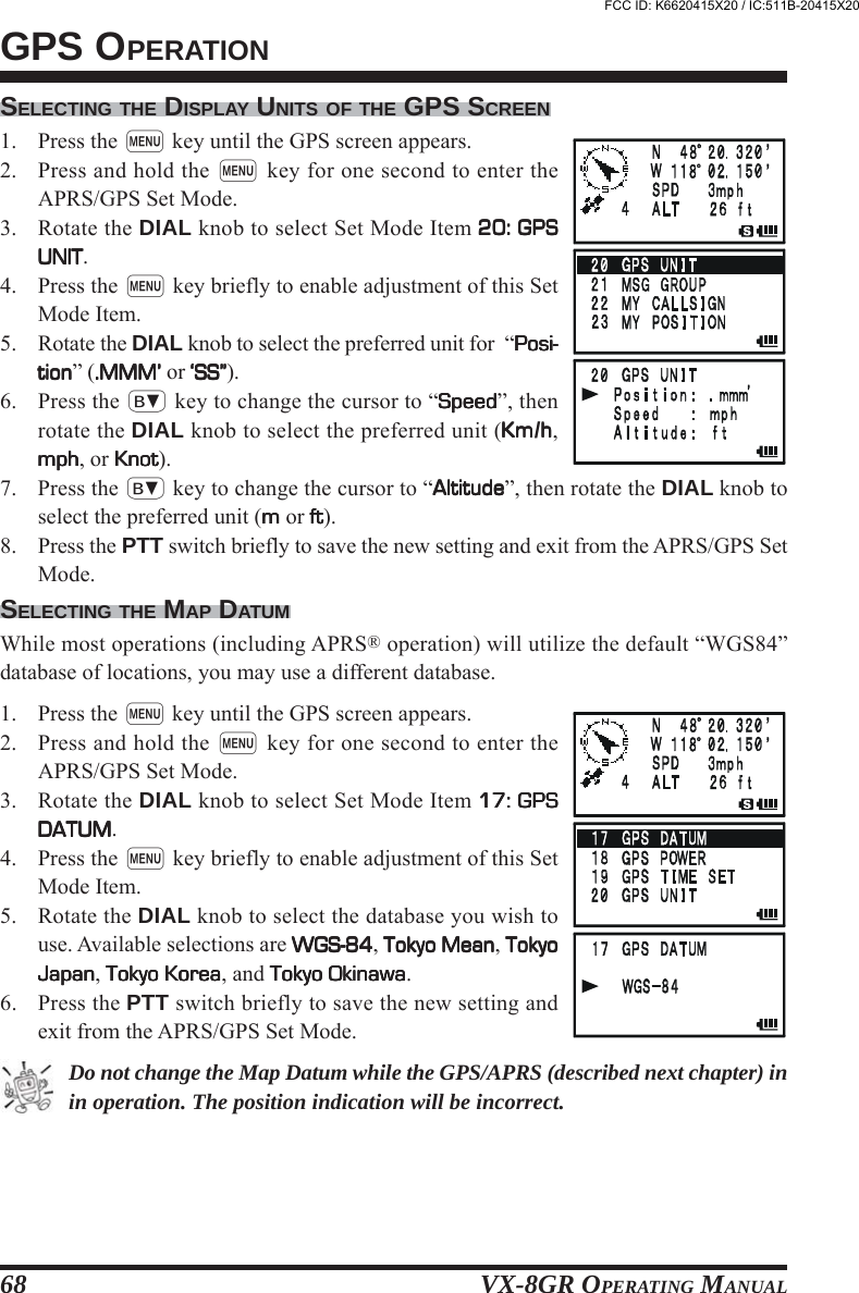
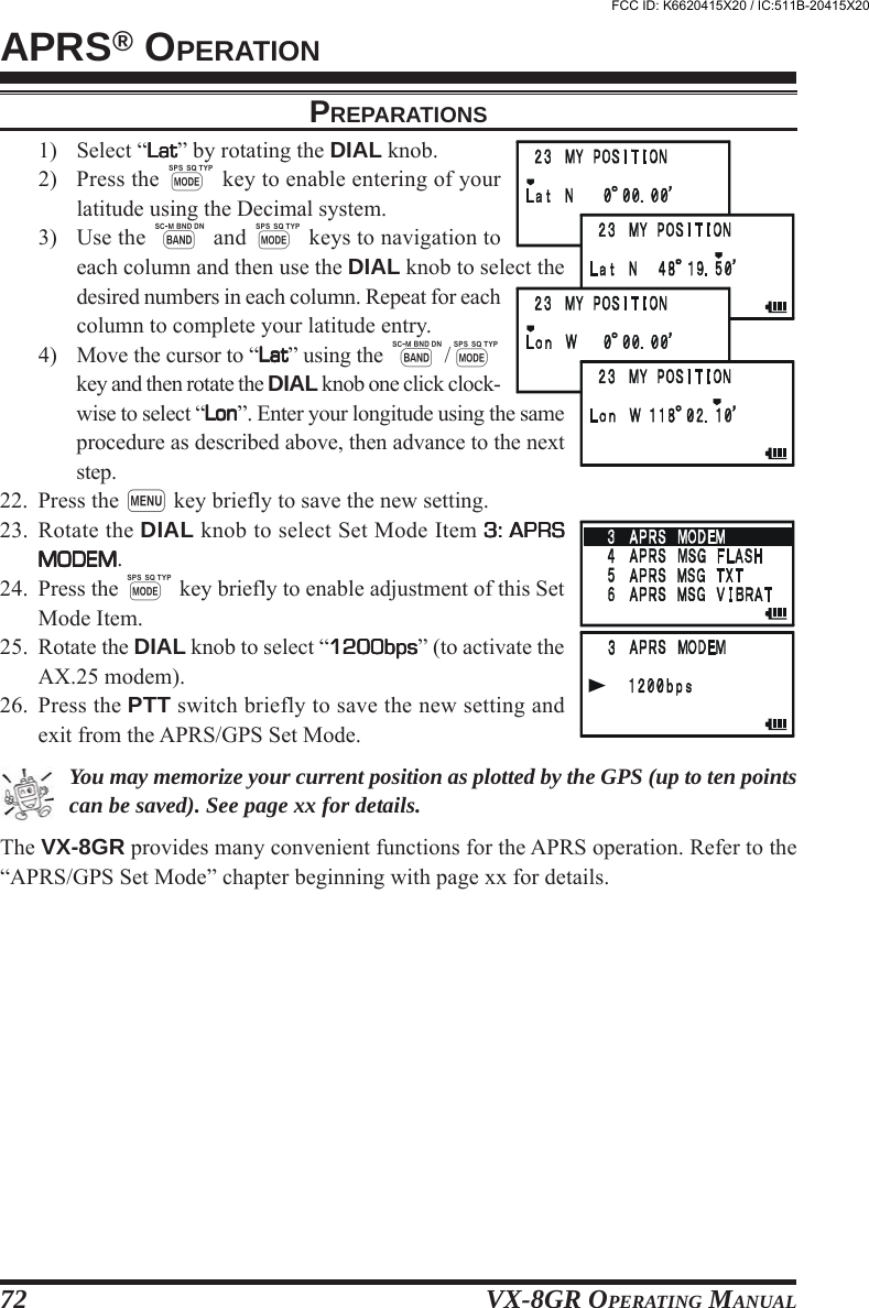
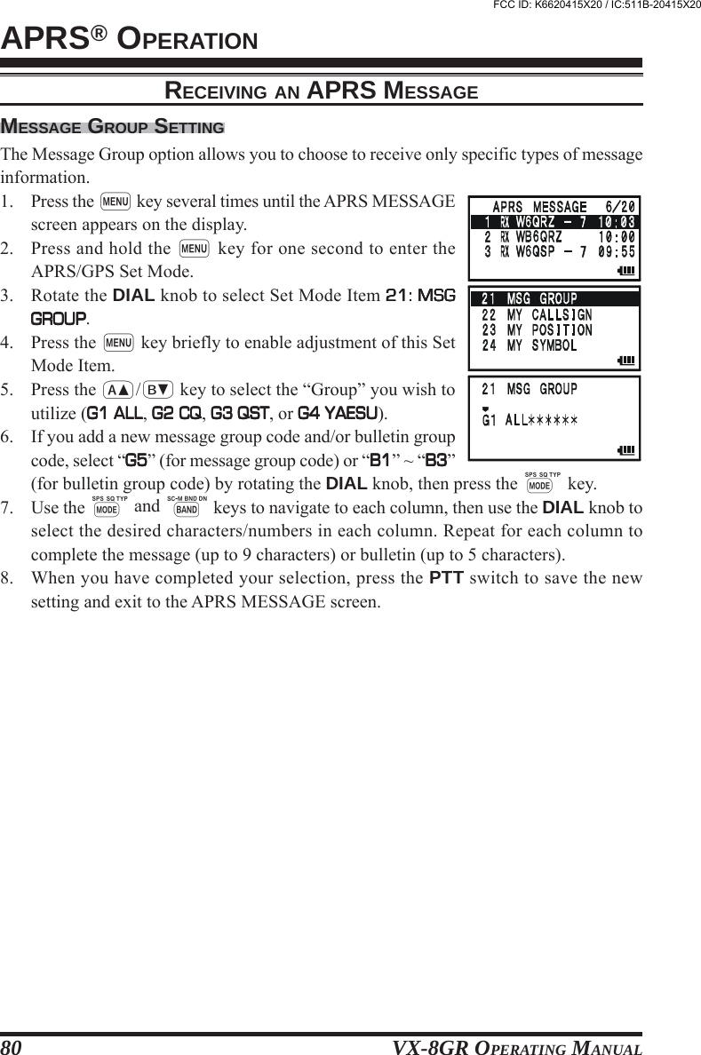
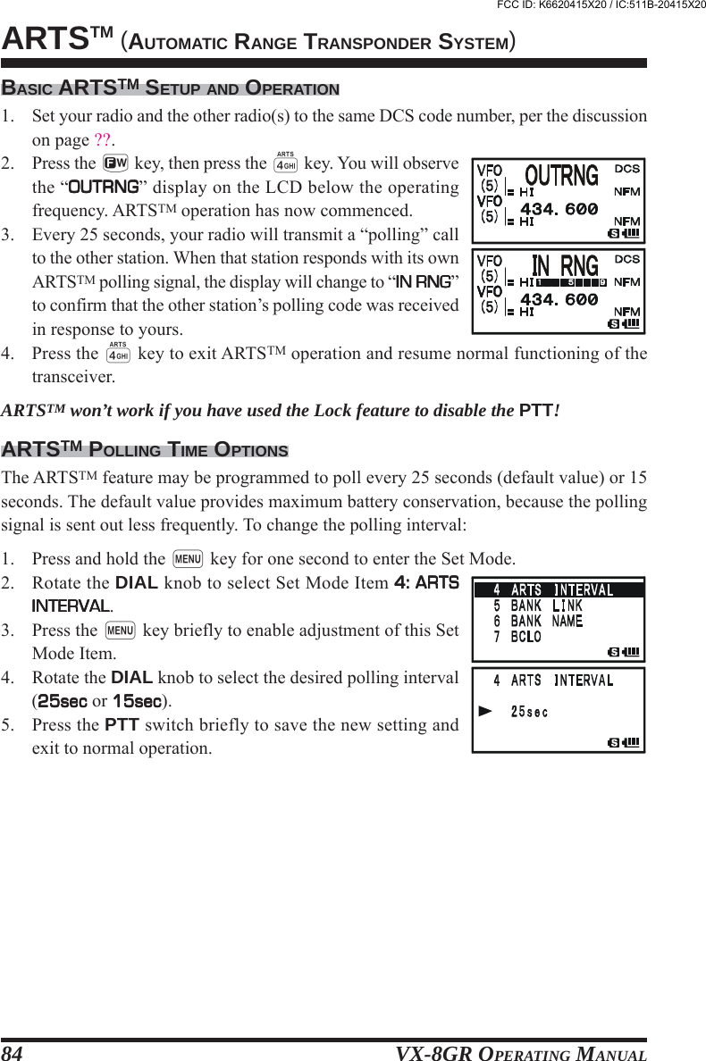
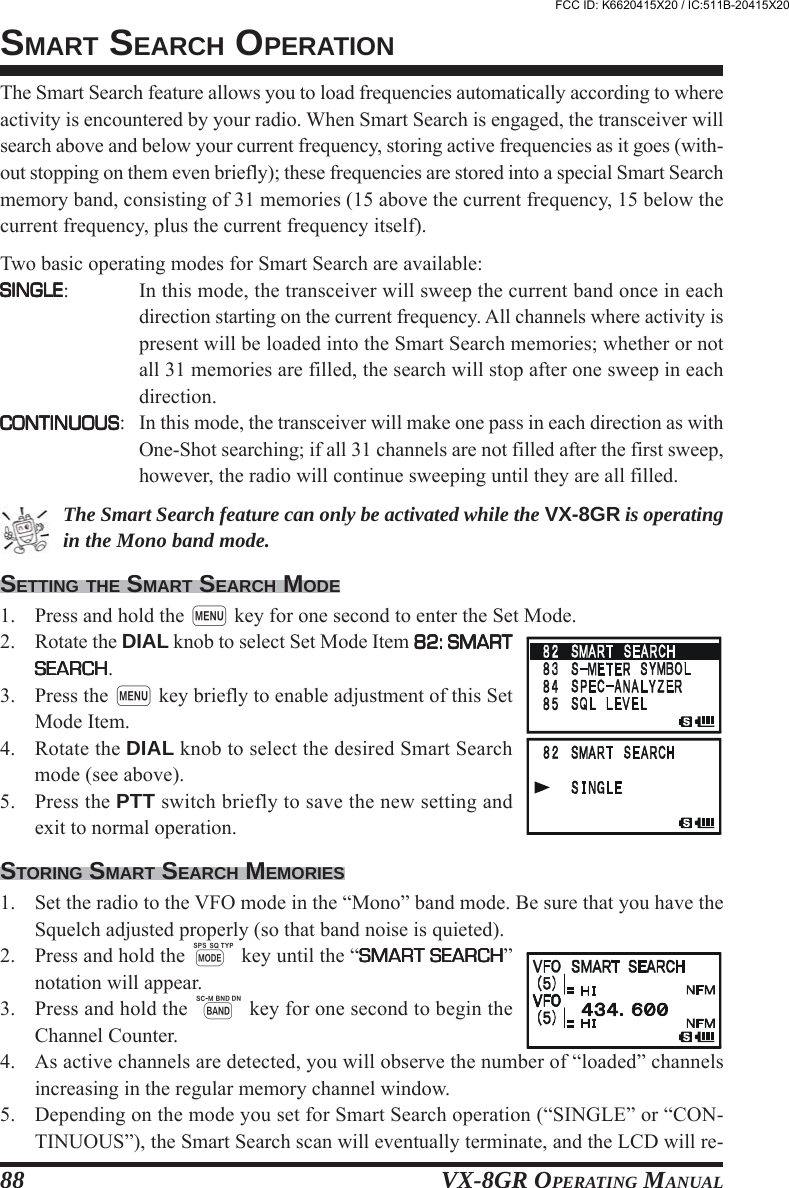
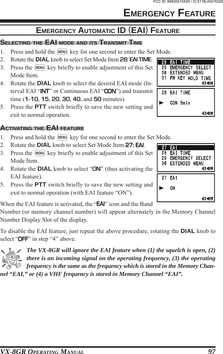
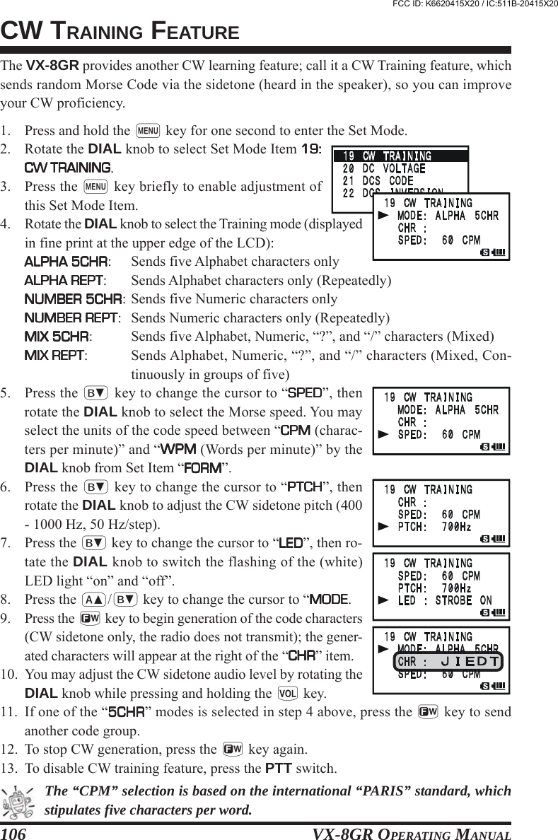
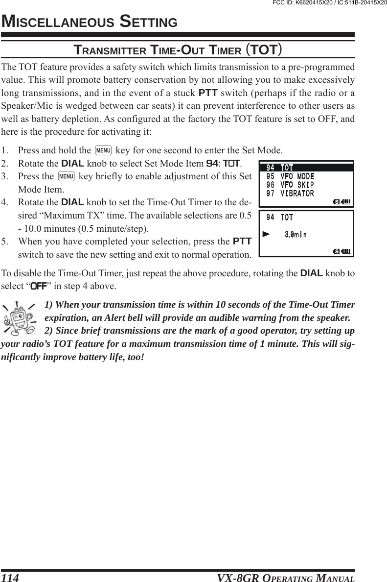
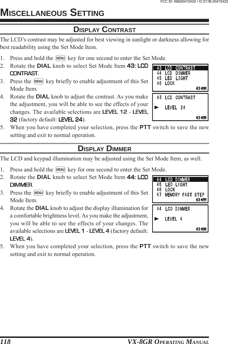
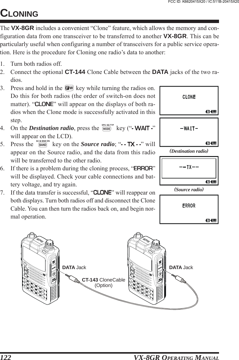
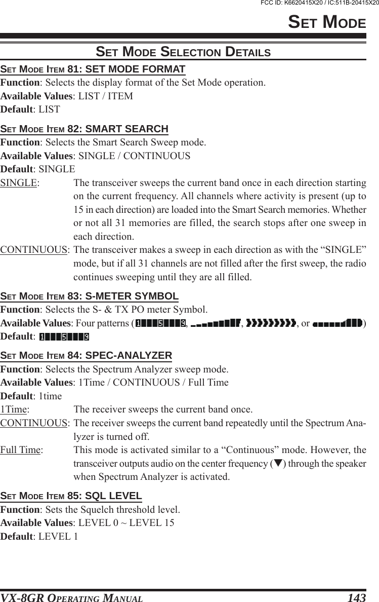
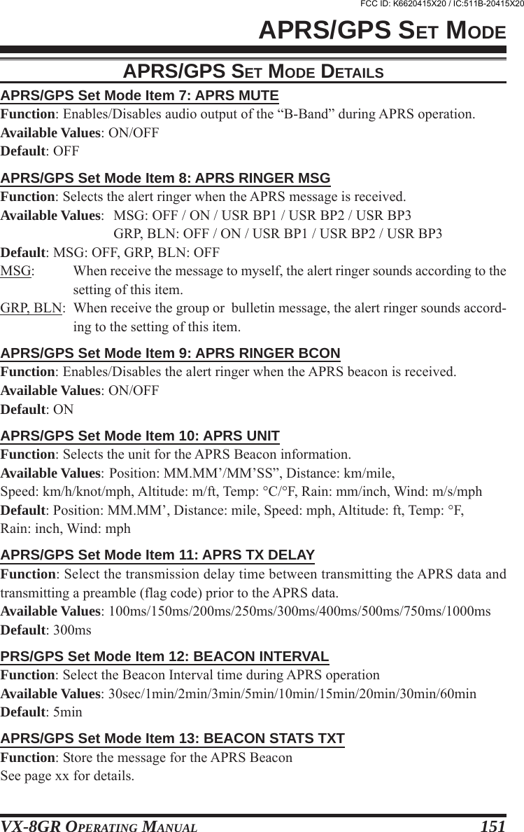
![VX-8GR OPERATING MANUAL 11INSTALLATION OF FBA-39 ALKALINE BATTERY CASE (OPTION)The optional FBA-39 Battery Case allows receive monitoring using three “AA” size Al-kaline batteries. Alkaline batteries can also be used for low power transmission in anemergency. The power output will only be selectable 1 W/50 mW (for 50/144/430 MHzFM) or 500 mW/50 mW (for 222 MHz FM), or 1 W fixed (for 50 MHz AM).TO INSTALL ALKALINE BATTERIES INTO THE FBA-391. Lift up the lower right corner of the rubber cover, and then open the cover (Figure 1).2. Referring to Figure 2, slide the batteries into the FBA-39 as shown in the illustration,with the Negative [–] side of the batteries touching the spring connections inside theFBA-39.3. Close the rubber cover.4. Install the FBA-39 in the transceiver in the same manner as the FNB-101LI.INSTALLATION OF ACCESSORIESThe FBA-39 does not provide connections for charging, since Alkaline cells cannot bere-charged. Therefore, the NC-86B/C, E-DC-5B, or E-DC-6 may safely be connected tothe EXT DC jack when the FBA-39 is installed.Notes:The FBA-39 is designed for use only with AA-type Alkaline cells.If you do not use the VX-8DR for a long time, remove the Alkaline batteries from theFBA-39, as battery leakage could cause damage to the FBA-39 and/or the trans-ceiver.Figure 1 Figure 2FCC ID: K6620415X20 / IC:511B-20415X20](https://usermanual.wiki/Yaesu-Musen/20415X20/User-Guide-1261125-Page-13.png)
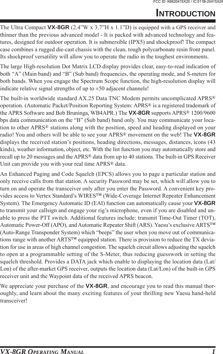
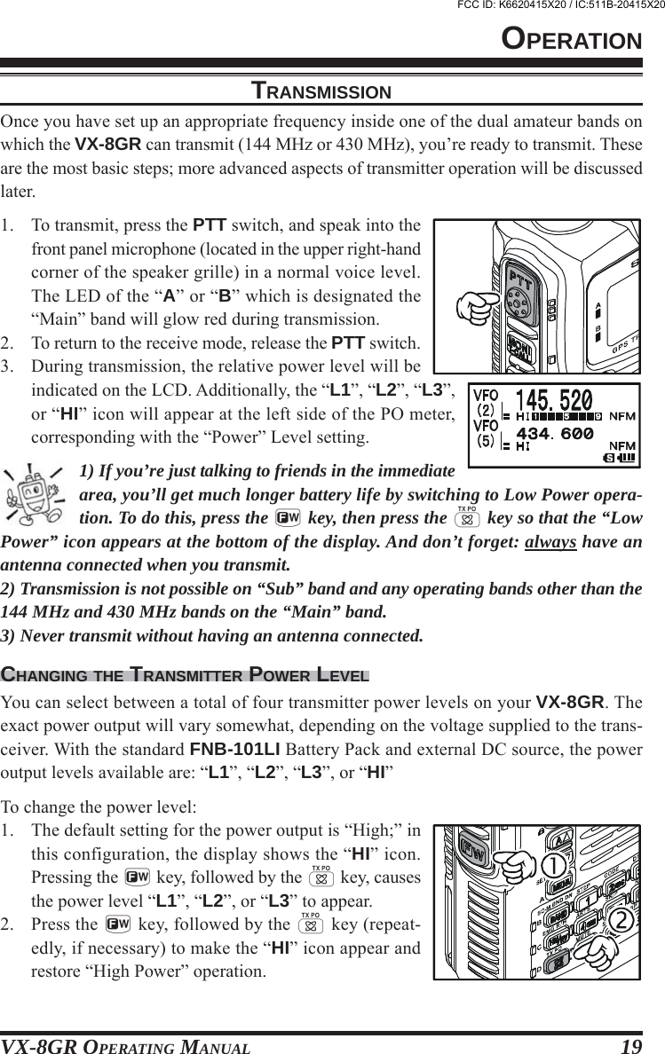
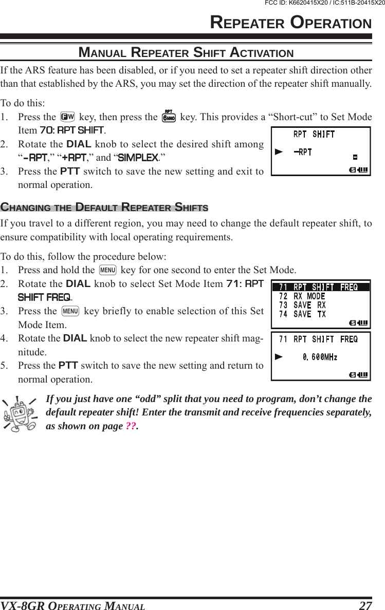
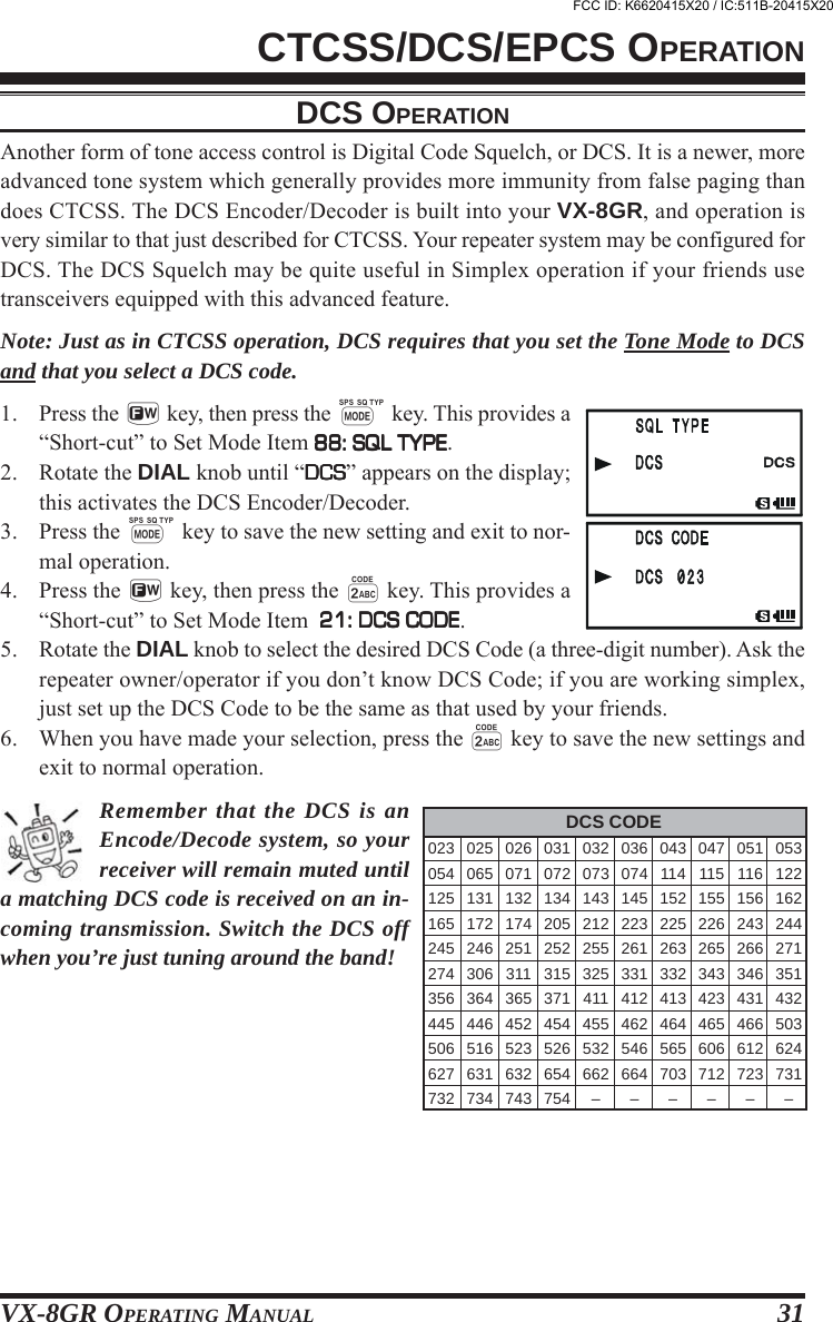
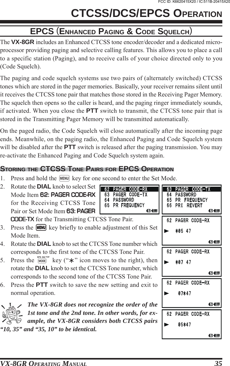
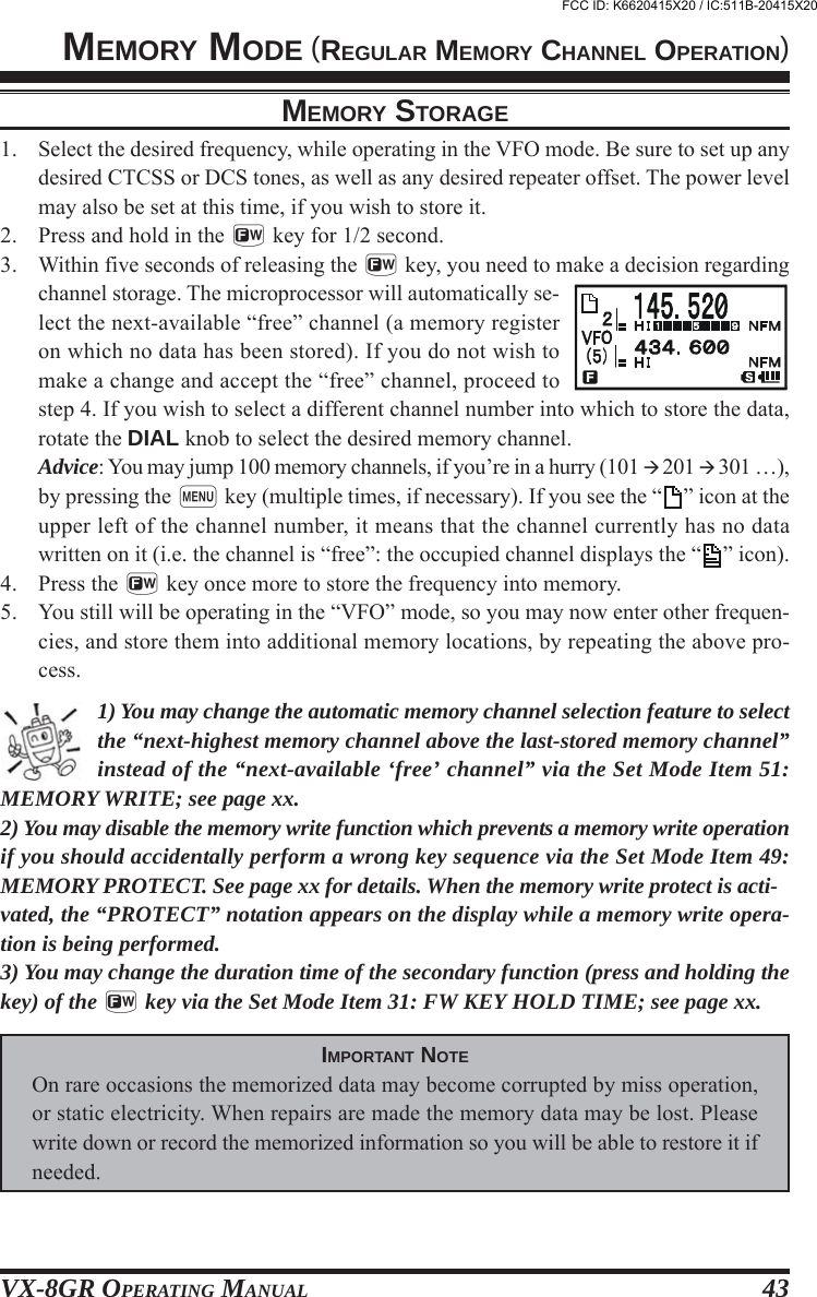
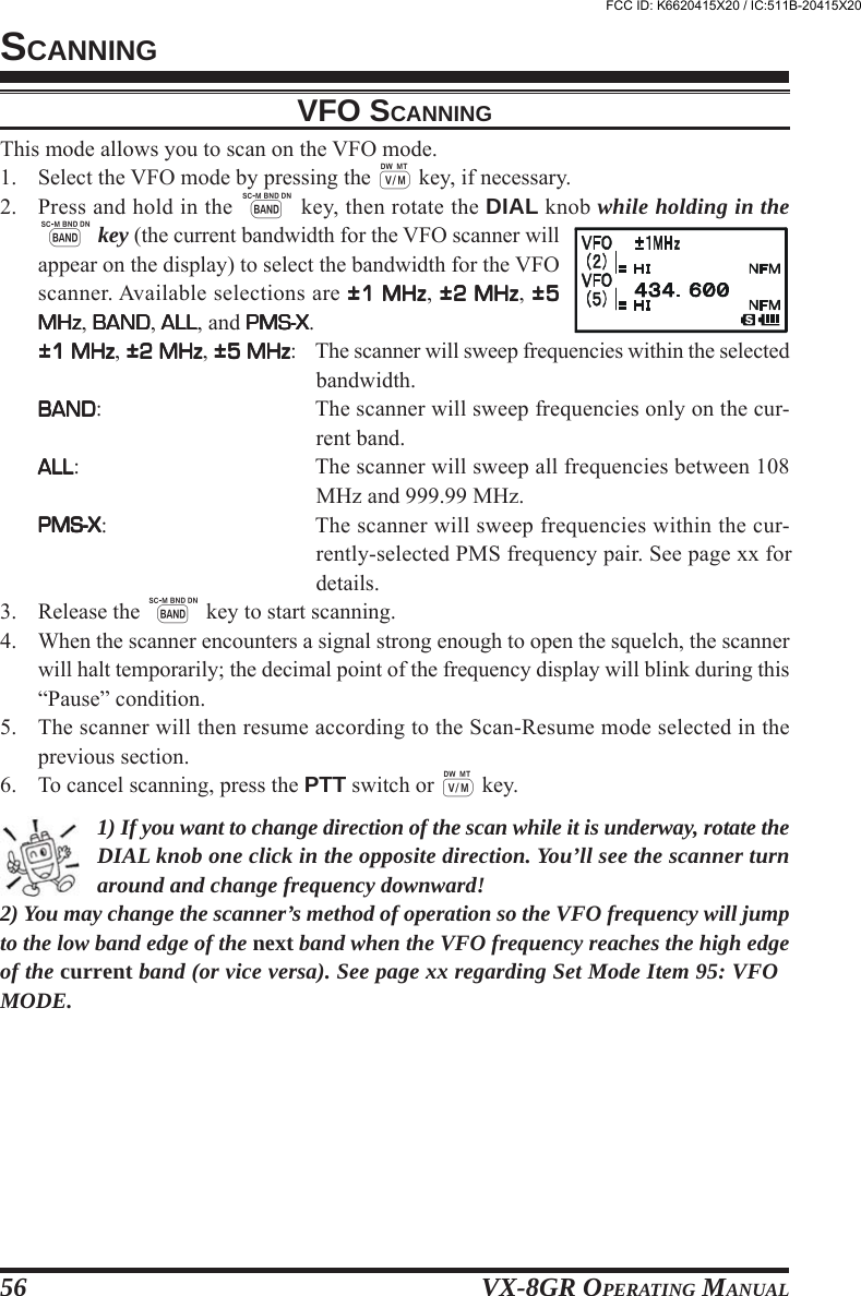
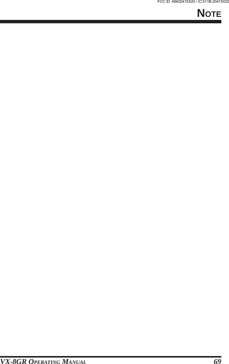
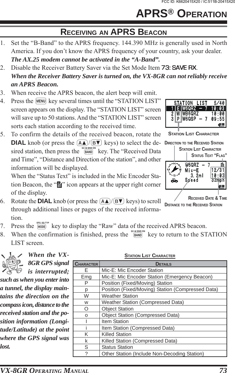
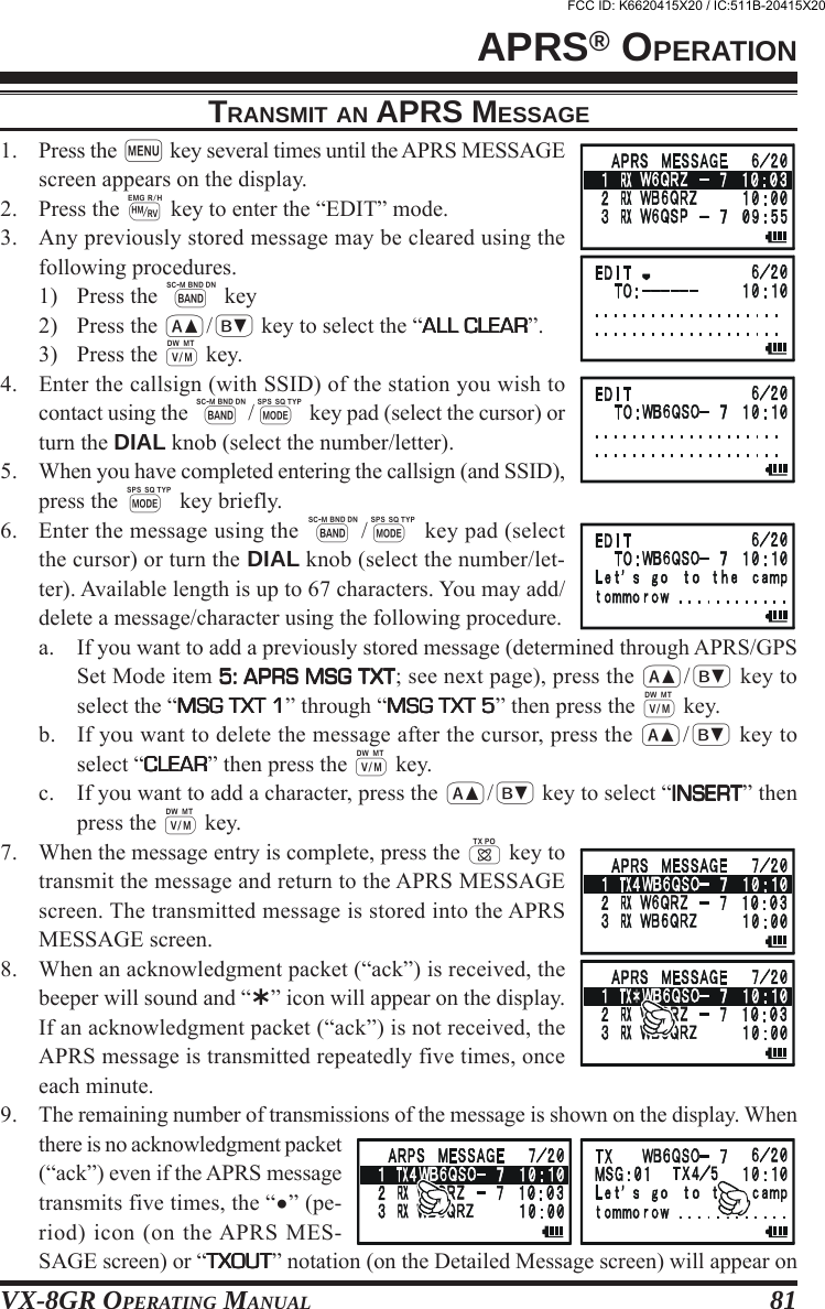
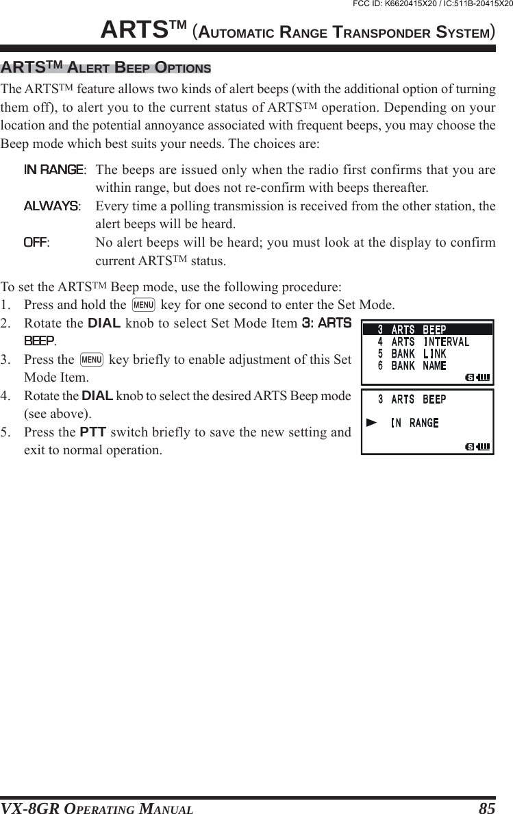
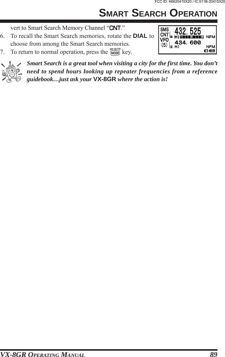
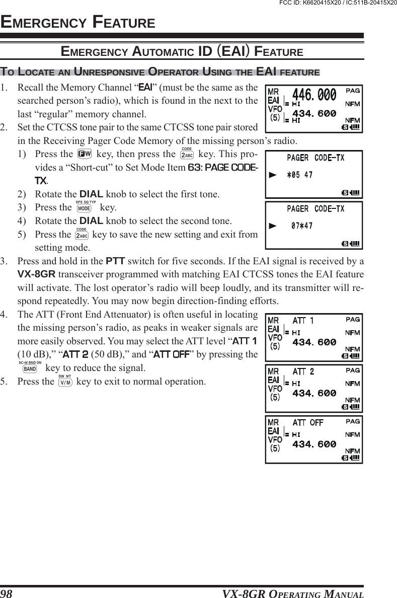
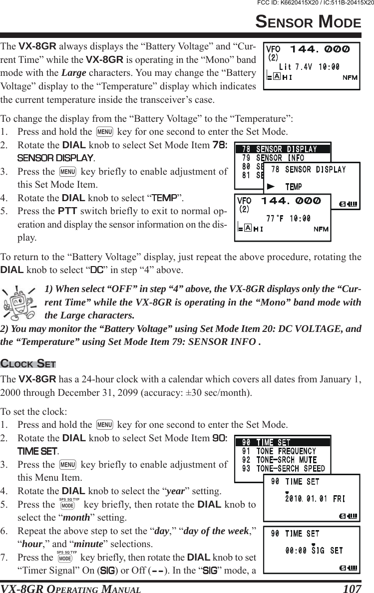
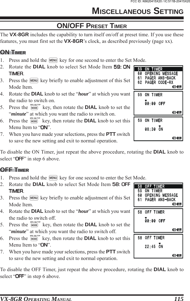
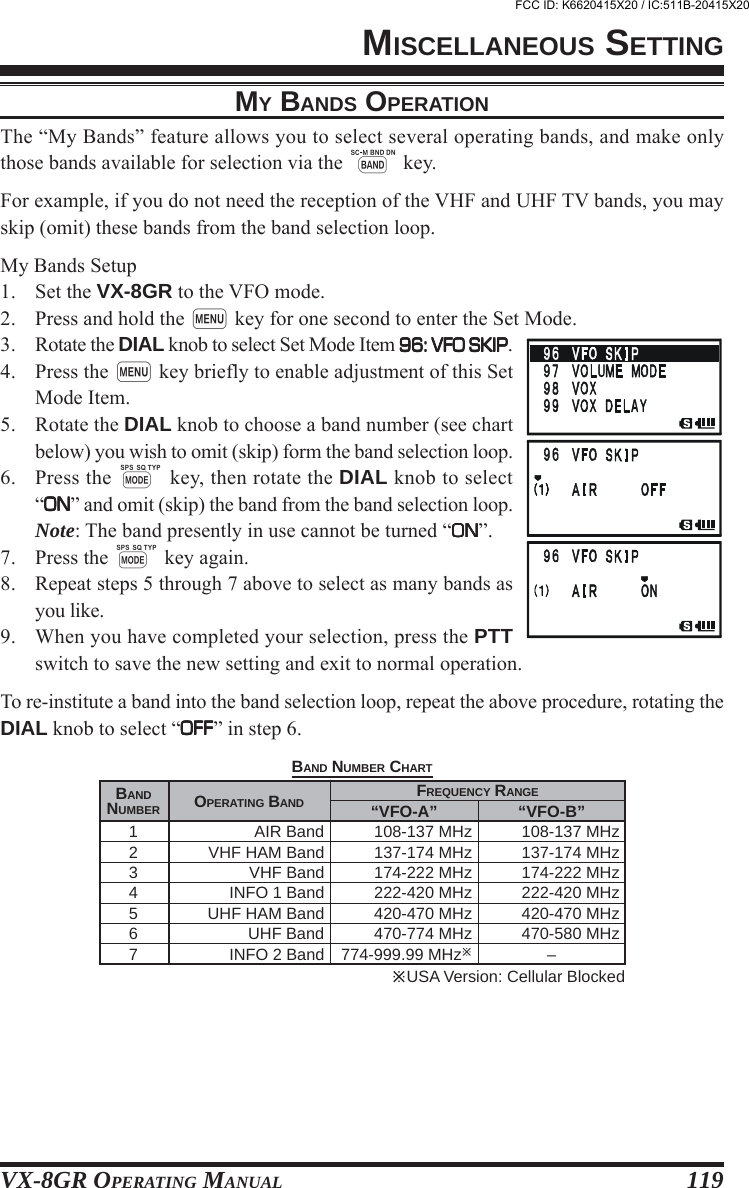
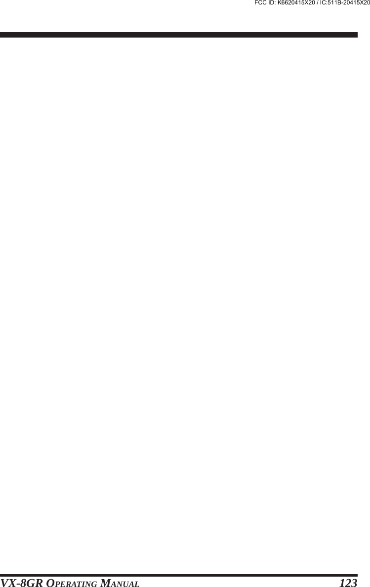
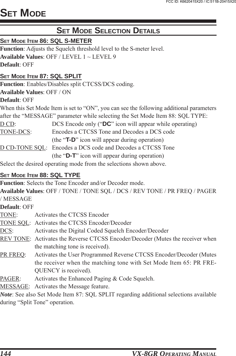
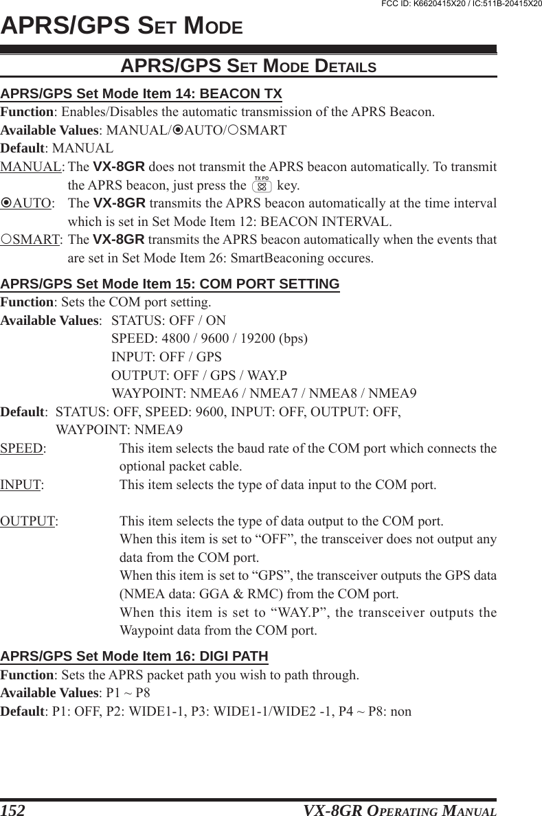
![VX-8GR OPERATING MANUAL16OPERATIONSELECTING THE FREQUENCY BANDThe VX-8GR covers an incred-ibly wide frequency range, overwhich a number of different op-erating modes are used. There-fore, the VX-8GR’s frequencycoverage has been divided intodifferent operating bands. Eachband has its own preset channelsteps and operating modes. You can change the channel steps and operating modes later, ifyou like (see page xx).TO CHANGE OPERATING BANDS1. Press the B key repeatedly. You will see the LCDindication change to a higher frequency band each timeyou press the B key. A Band Number according tothe receiving frequency is also displayed.2. If you wish to move the operating band selection down-ward (toward lower frequencies), press the f keyfirst, then press the B key.3. The VX-8DR uses a dual VFO system (described previously). To switch TX/RX op-eration from the “VFO-A” to the “VFO-B” instantly, press the b key briefly. Pressingthe a key will return TX/RX operation to “VFO-A”. The frequency band shown in“Large” characters is the band on which transmission is possible; the band shown in“Small” characters may only be used for reception.4. Once you have selected the desired band, you may initiate manual tuning (or scan-ning). See the discussions on the next page.If desired, you may omit (skip) one or more bands from the band selectionloop for faster recall of your favorite operating bands. See page xx for de-tails.OPERATING BAND[BAND NUMBER]AIR BandVHF HAM BandVHF BandINFO 1 BandUHF HAM BandUHF BandINFO 2 Band USA Version: Cellular BlockedFREQUENCY RANGE[1][2][3][4][5][6][7]“VFO-B”108-137 MHz137-174 MHz174-222 MHz222-420 MHz420-470 MHz470-580 MHz–“VFO-A”108-137 MHz137-174 MHz174-222 MHz222-420 MHz420-470 MHz470-800 MHz800-999.99 MHzFCC ID: K6620415X20 / IC:511B-20415X20](https://usermanual.wiki/Yaesu-Musen/20415X20/User-Guide-1261125-Page-18.png)
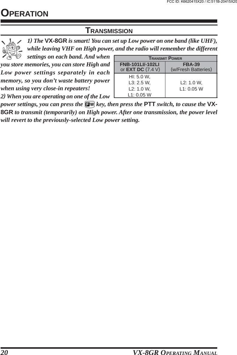
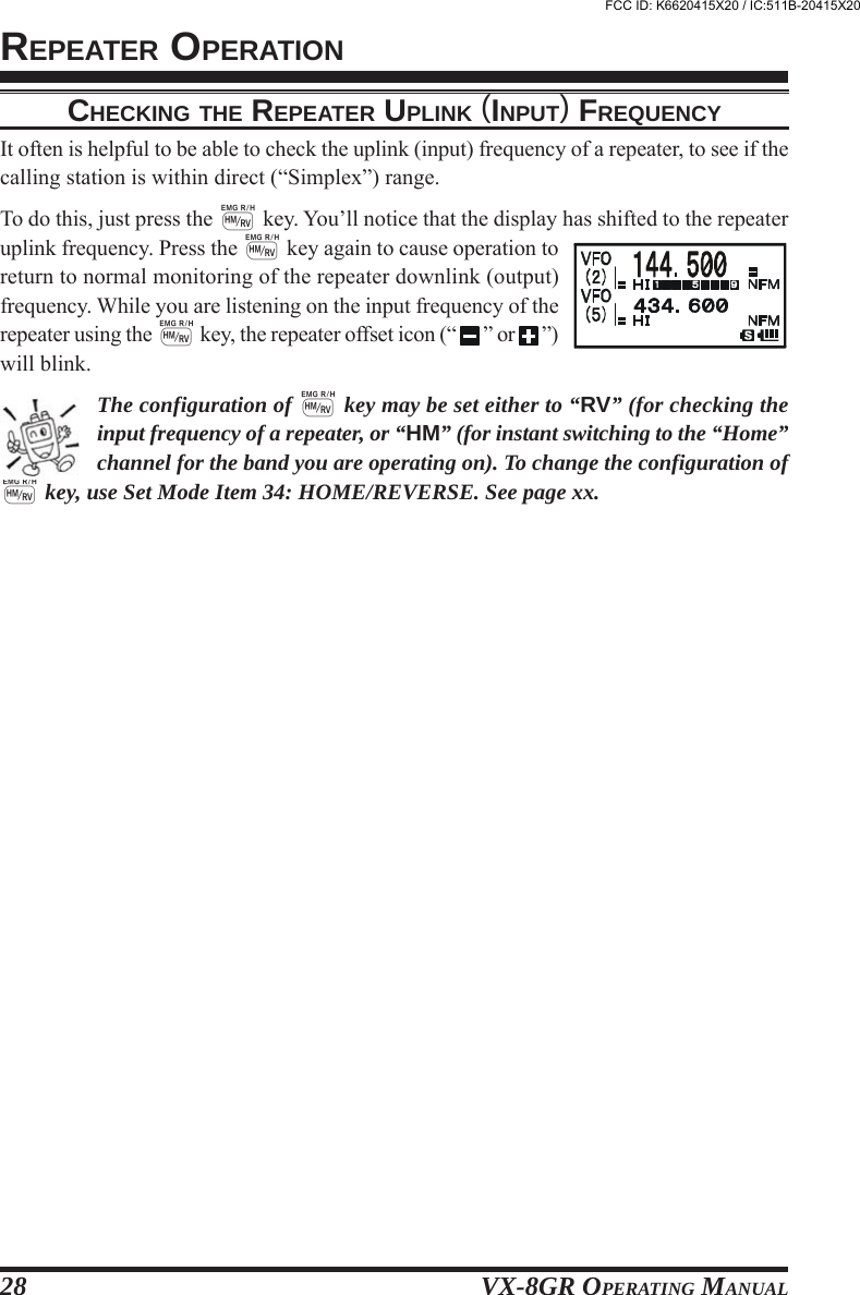
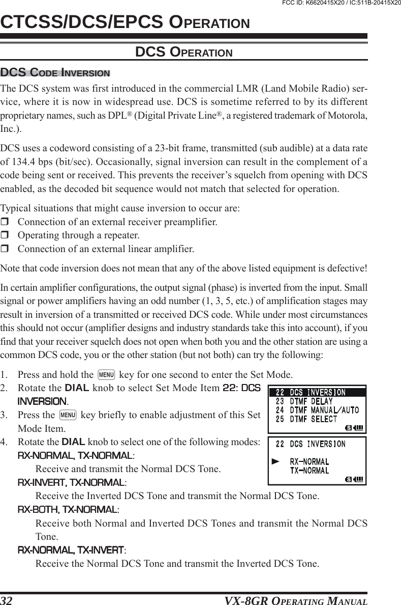
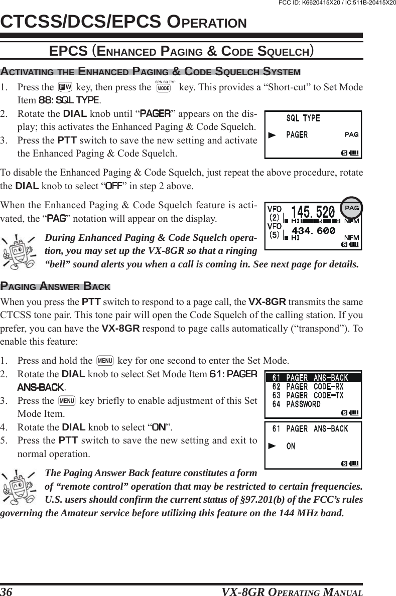
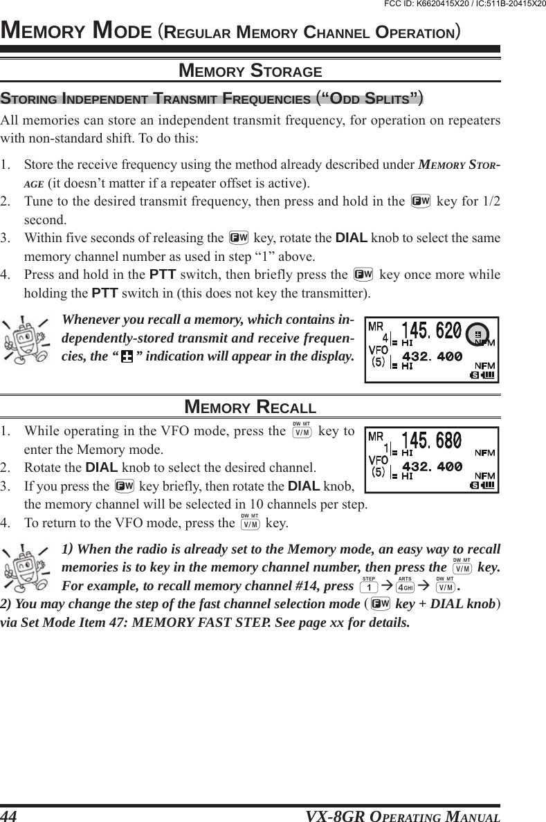
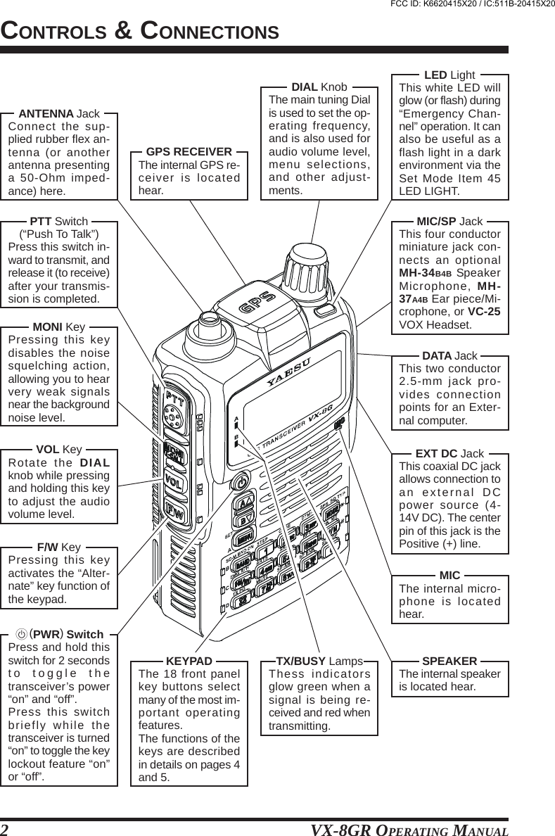
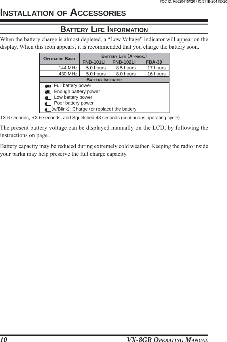
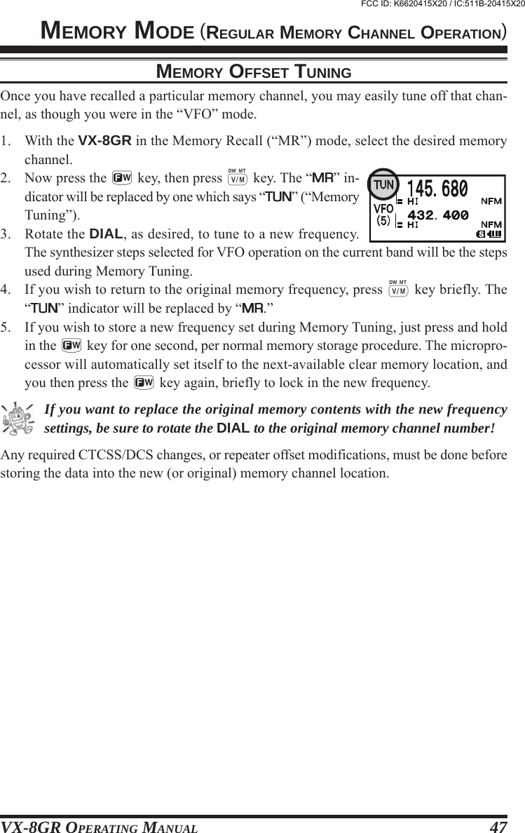
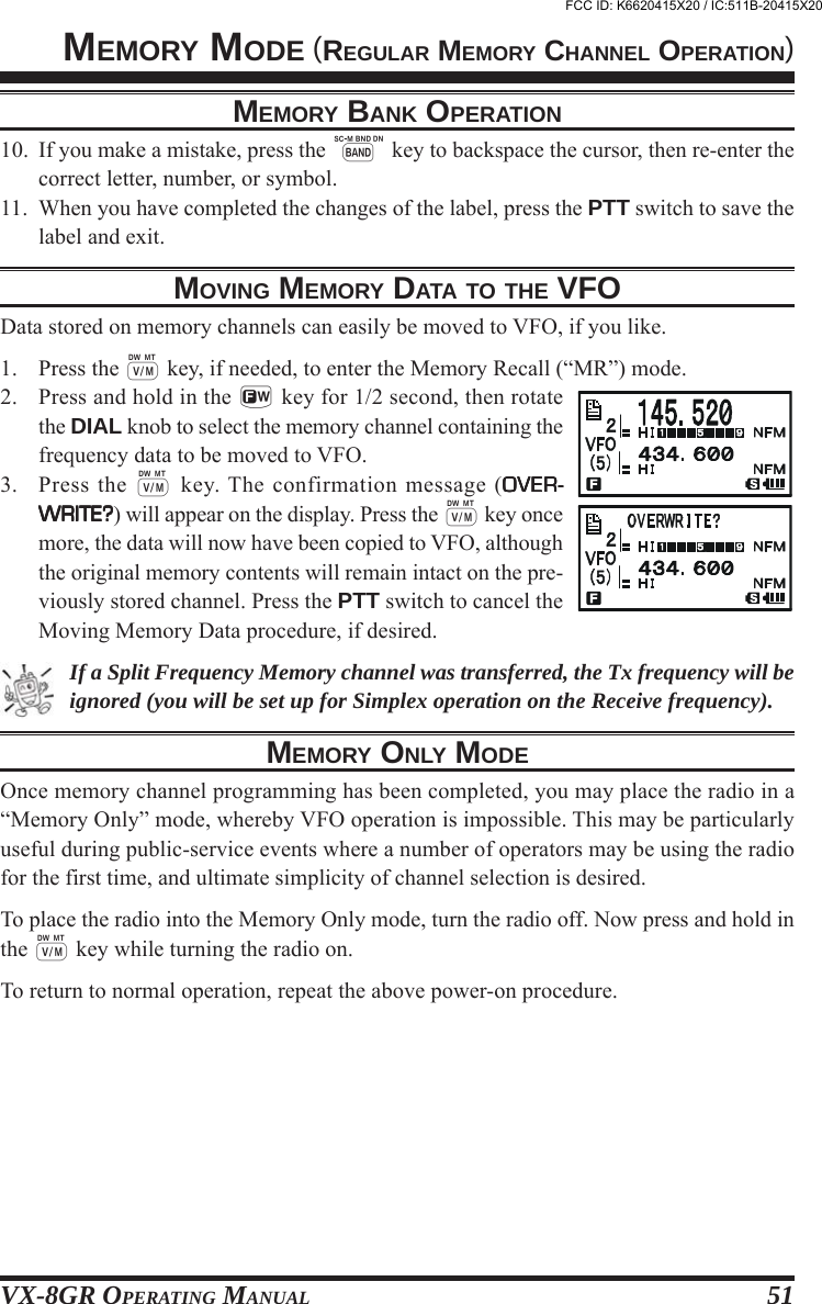
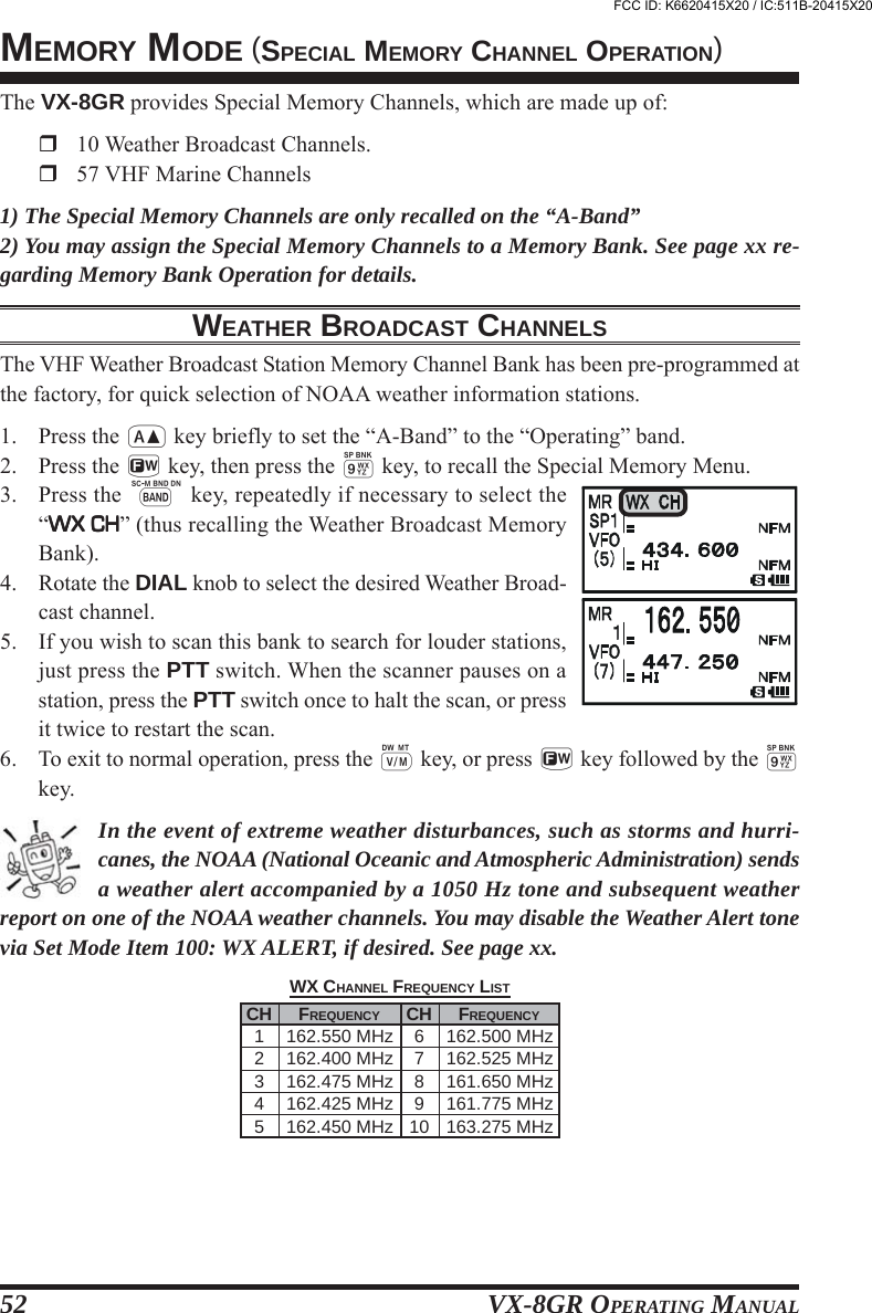
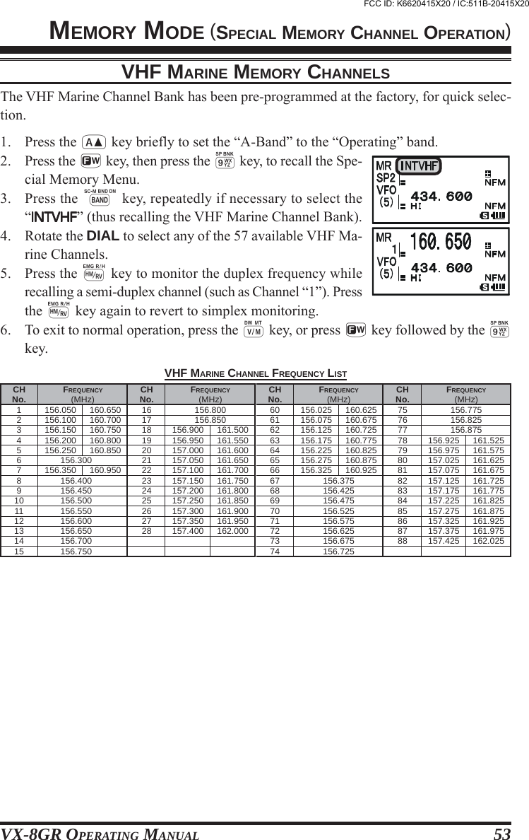
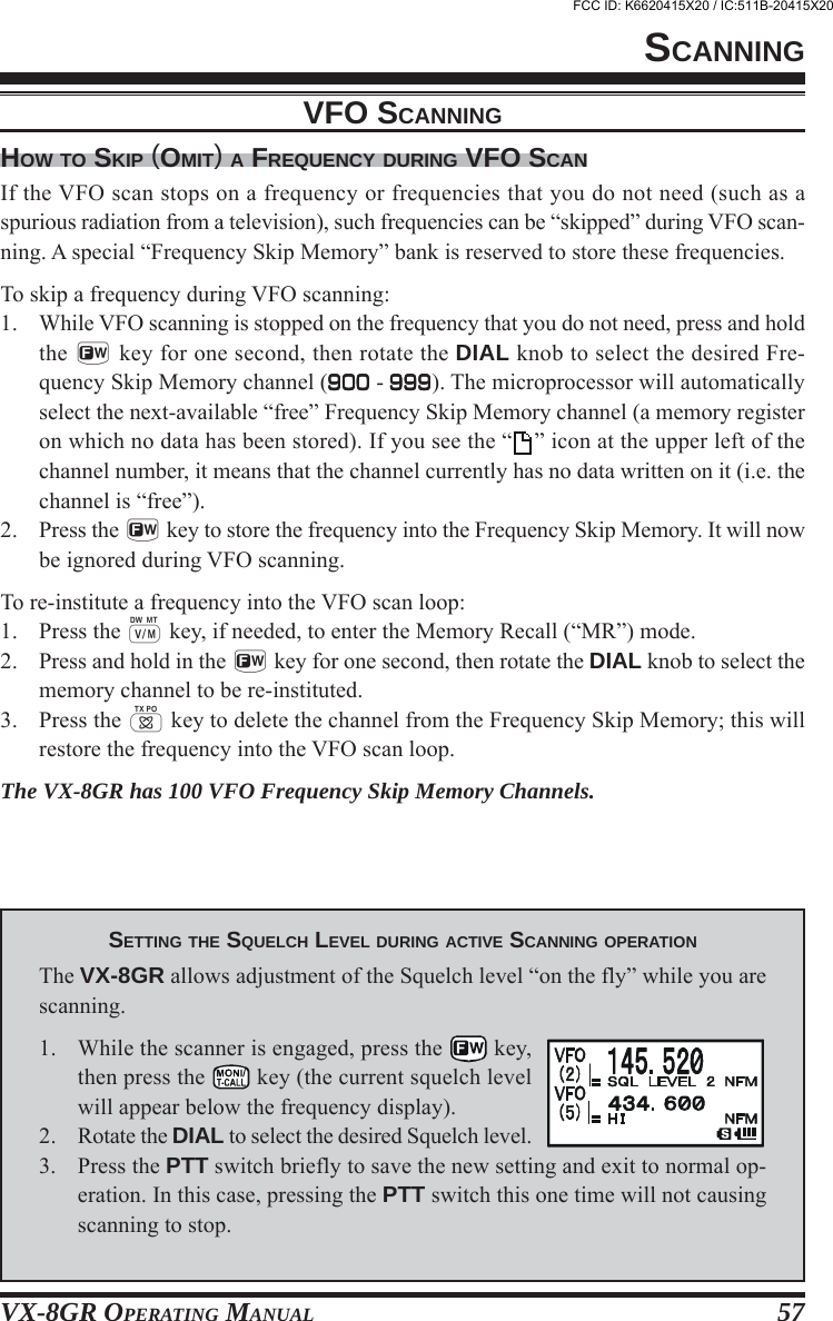
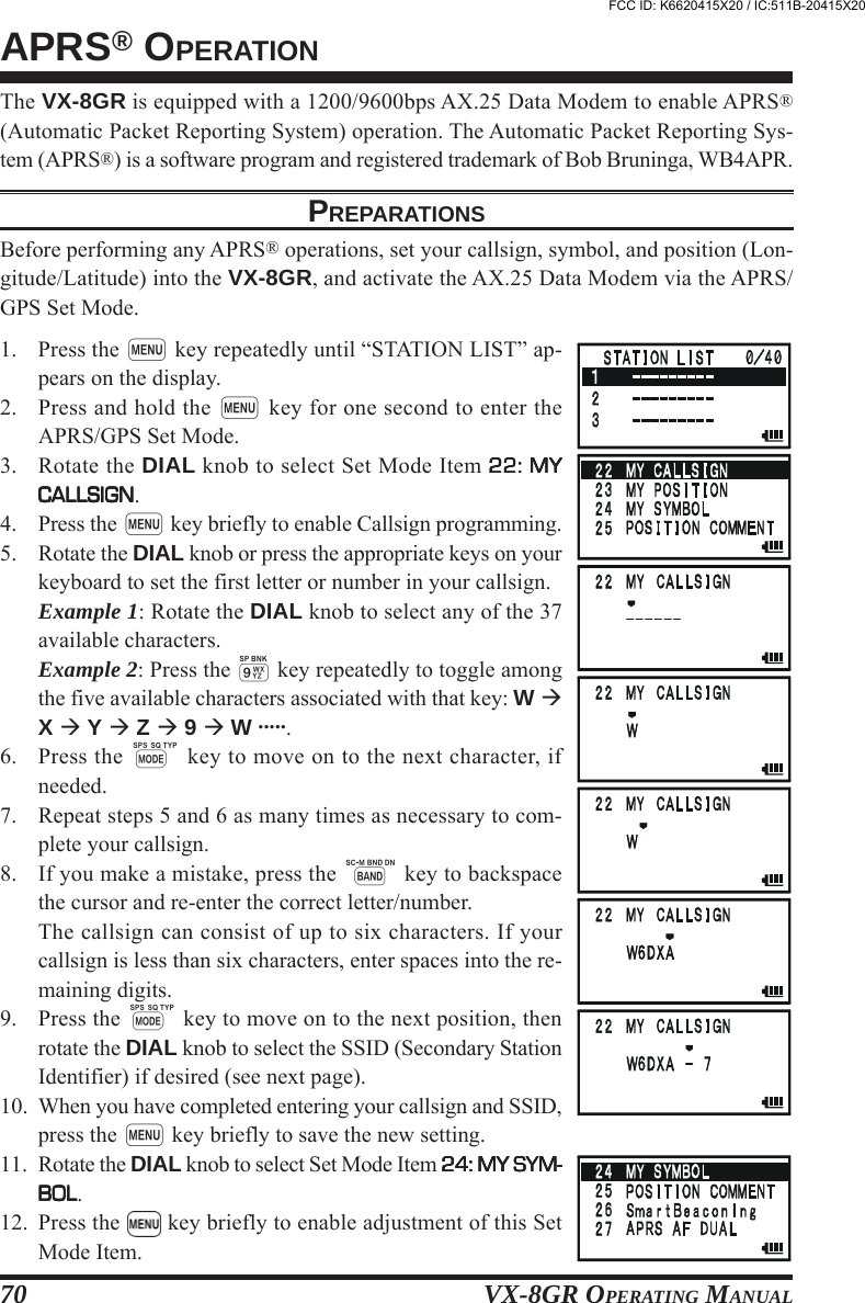
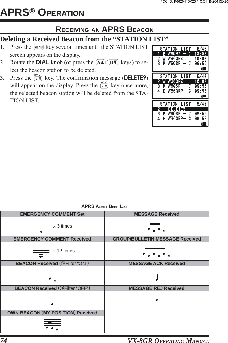
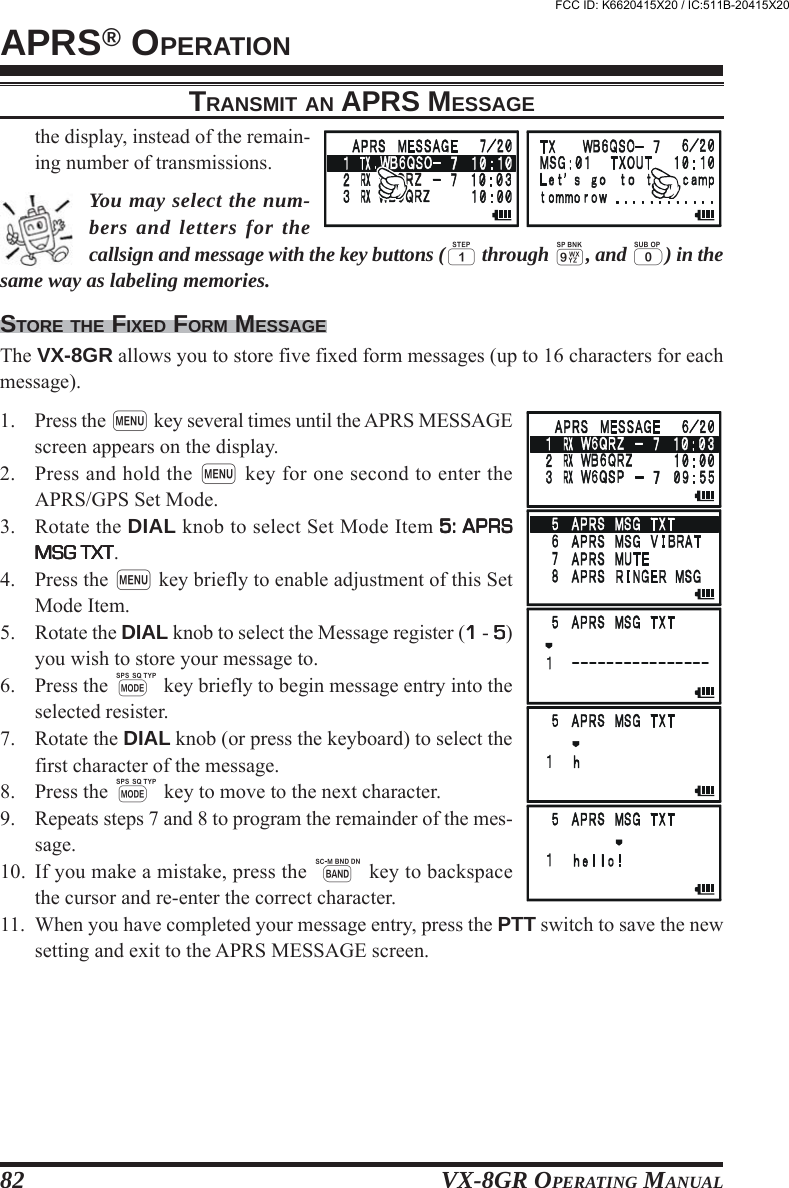
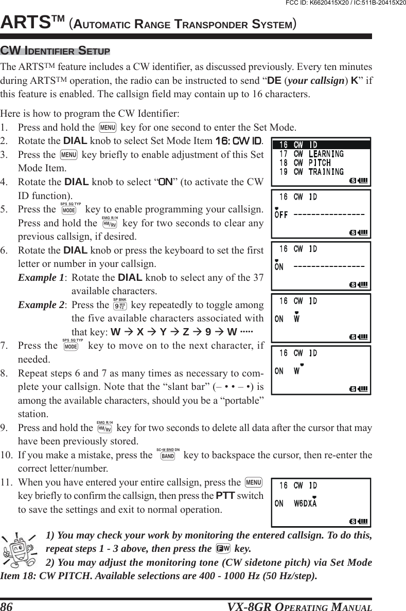
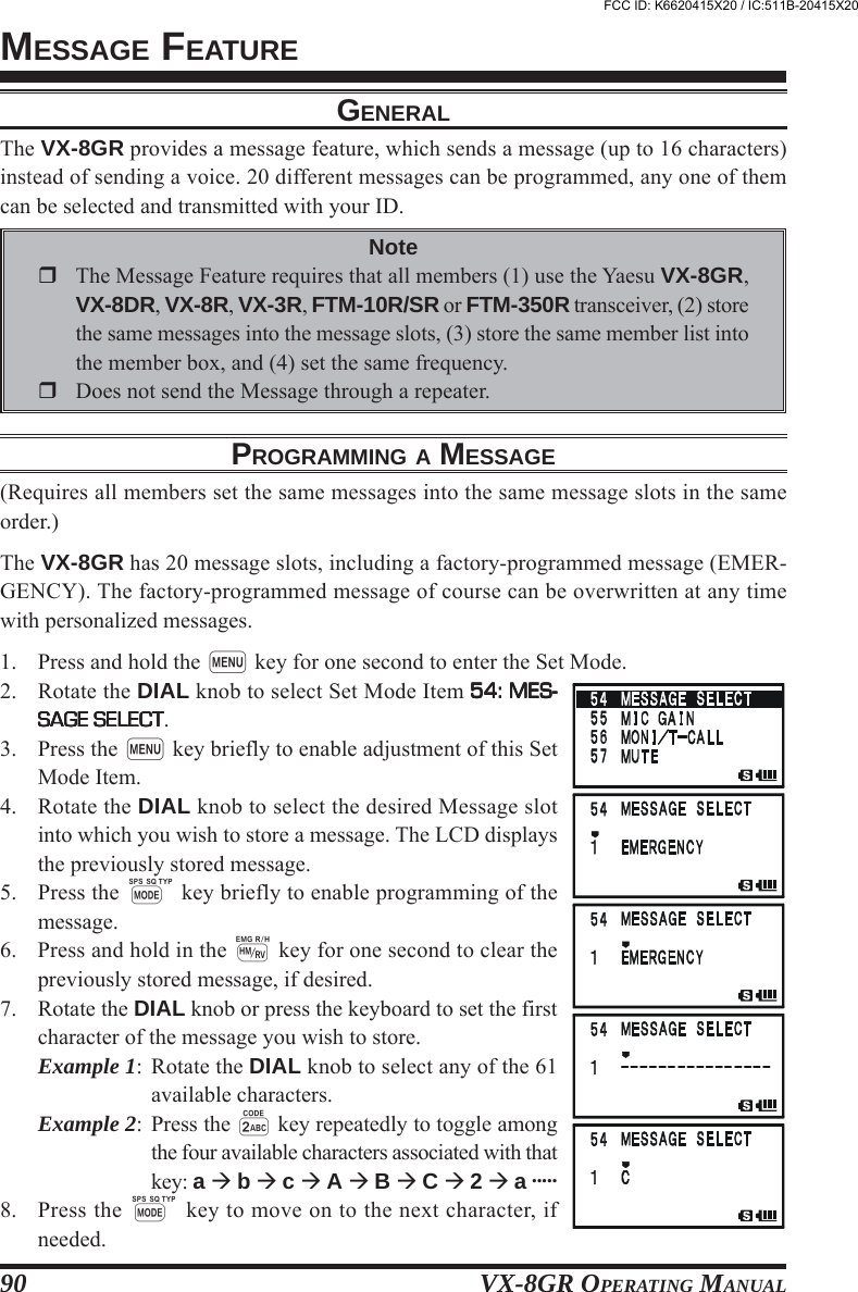
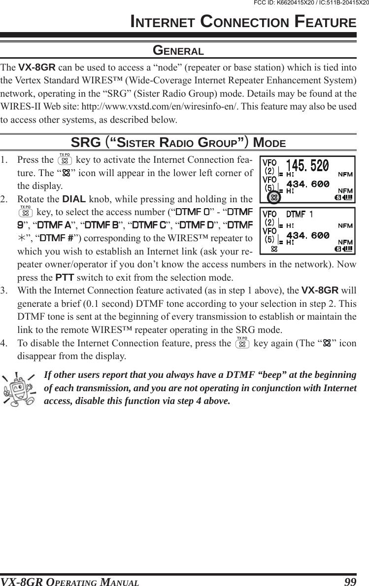
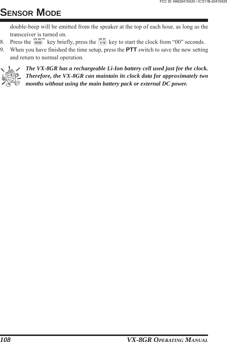
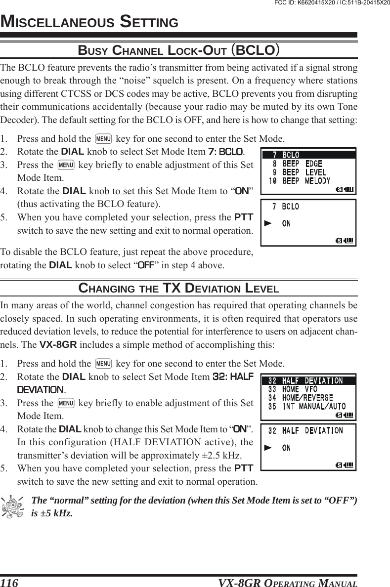
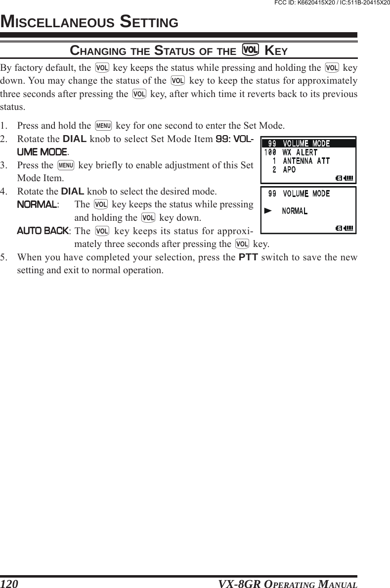
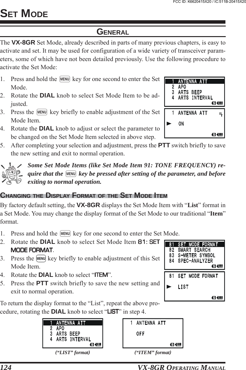
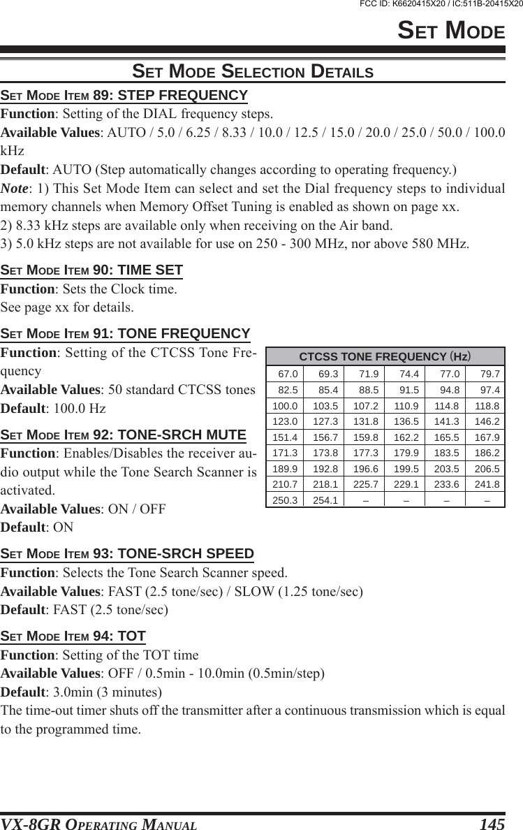
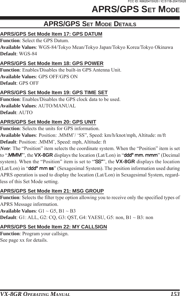
![VX-8GR OPERATING MANUAL 45A special one-touch “HOME” channel is available for each operating band, to allow quickrecall of a favorite operating frequency on each band.HOME CHANNEL RECALL1. Press the f key, then press the h key to recall the HomeChannel on the band group where you are currently operat-ing.2. Press the f key, then press the h key again to return tothe previously-used frequency (either a VFO or a memory channel).The transceiver switches to VFO mode if the DIAL knob is turned.You may disable the above function (automatically switching to the VFO mode)using Set Mode Item 33: HOME VFO.HOME CHANNEL FREQUENCY CHANGEThe factory defaults for the Home channels are listed below. You may re-program theHome channel in a manner identical to that used for the regular memories:1. Select the desired frequency, while operating in the VFO mode. Be sure to set up anydesired CTCSS or DCS tones, as well as any desired repeater offset. The power levelmay also be set at this time, if you wish to store it.2. Press and hold in the f key for 1/2 second.3. While the memory channel number is blinking, just press the h key. The frequencyand other data (if any) will now be stored in the special HOME channel register.4. You may repeat this process on the other operating bands.Note that the UHFHOME channel isthe one used during“Emergency” operation. Seepage xx for details regardingthis feature.MEMORY MODE (REGULAR MEMORY CHANNEL OPERATION)HOME CHANNEL MEMORYOPERATING BAND[BAND NUMBER]Air Band [1]VHF HAM Band [2]VHF Band [3]Information Band 1 [4]UHF HAM Band [5]UHF Band [6]Information Band 2 [7]EXP VERSION108.000 MHz144.000 MHz174.000 MHz222.000 MHz430.000 MHz470.000 MHz860.000 MHzUSA VERSION108.000 MHz146.520 MHz174.000 MHz222.000 MHz446.000 MHz470.000 MHz860.000 MHzDEFAULT HOME CHANNELSFREQUENCYFCC ID: K6620415X20 / IC:511B-20415X20](https://usermanual.wiki/Yaesu-Musen/20415X20/User-Guide-1261125-Page-47.png)
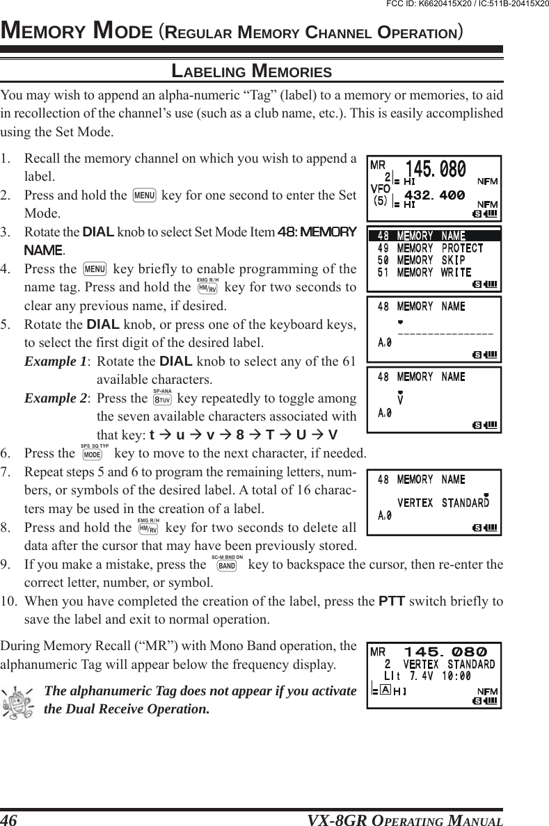
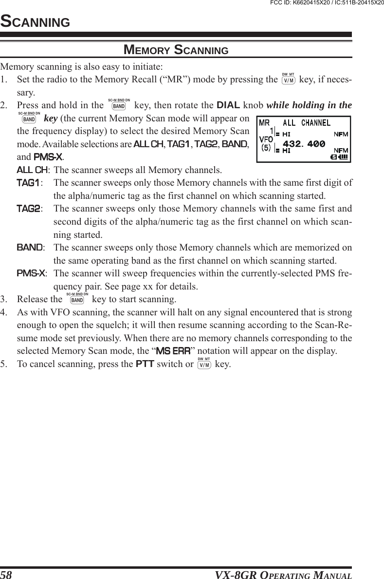

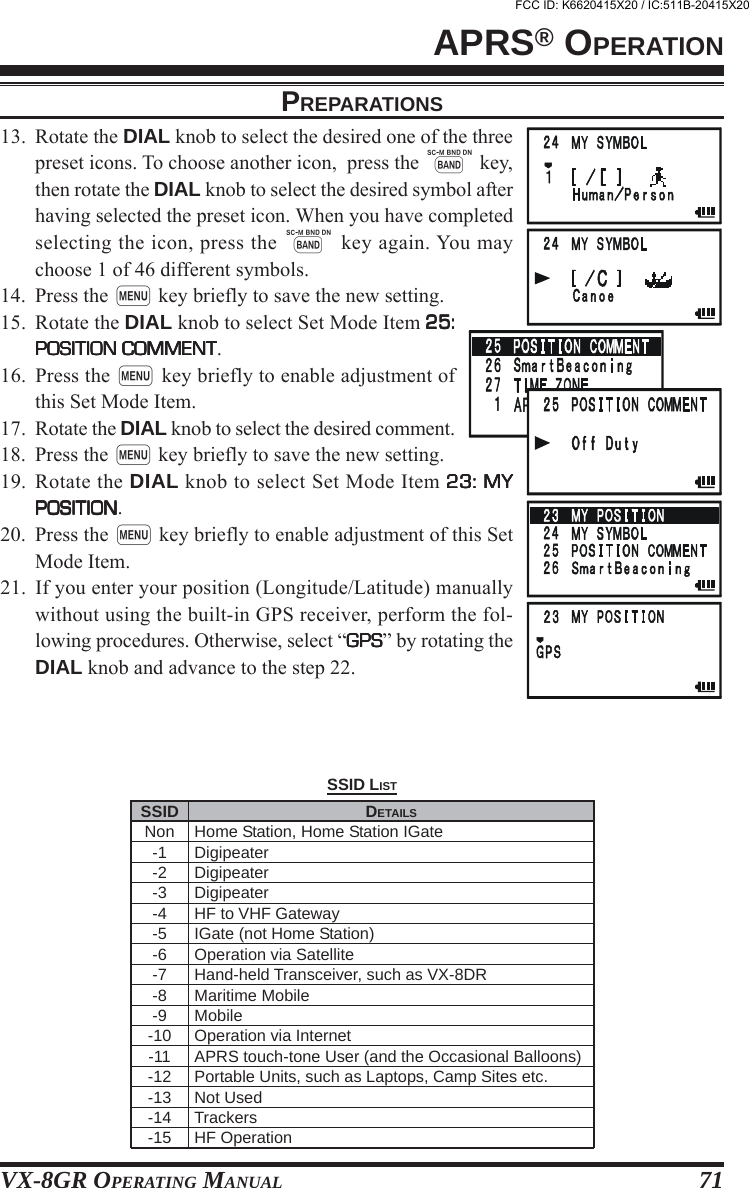
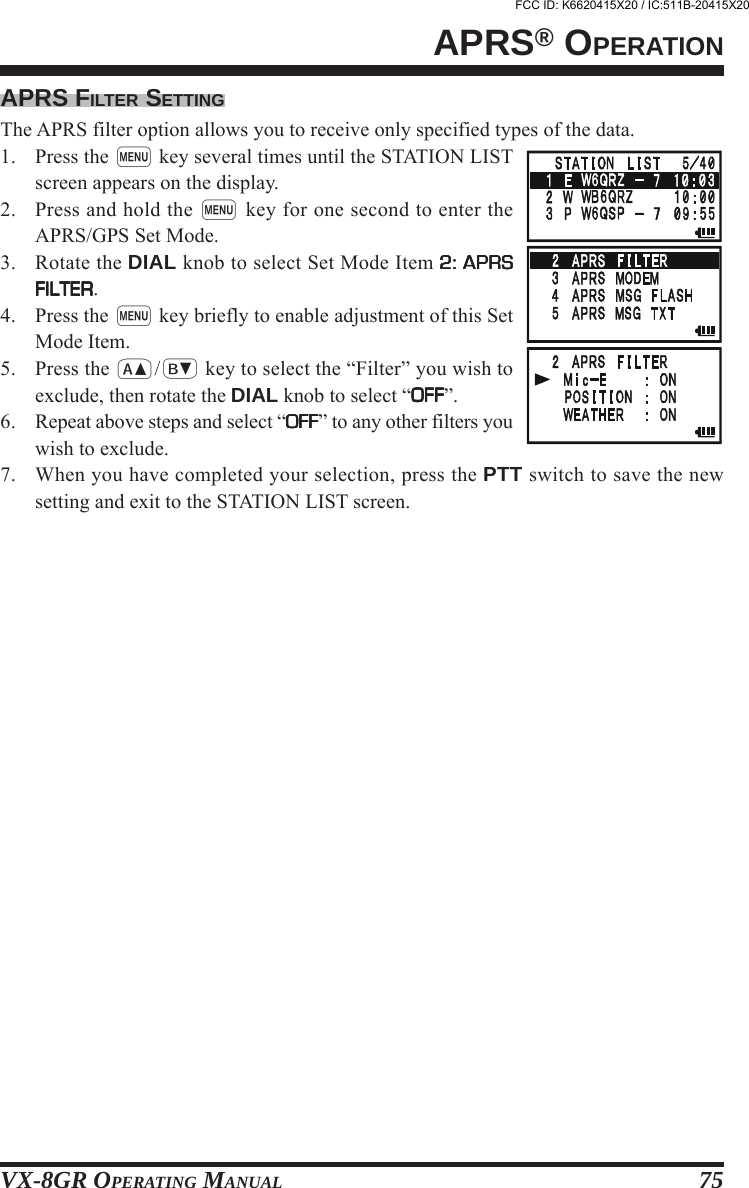
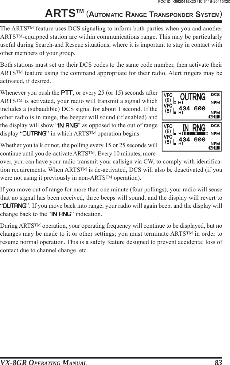
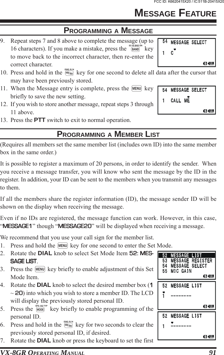
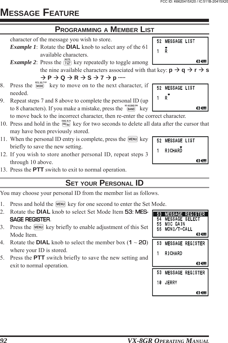
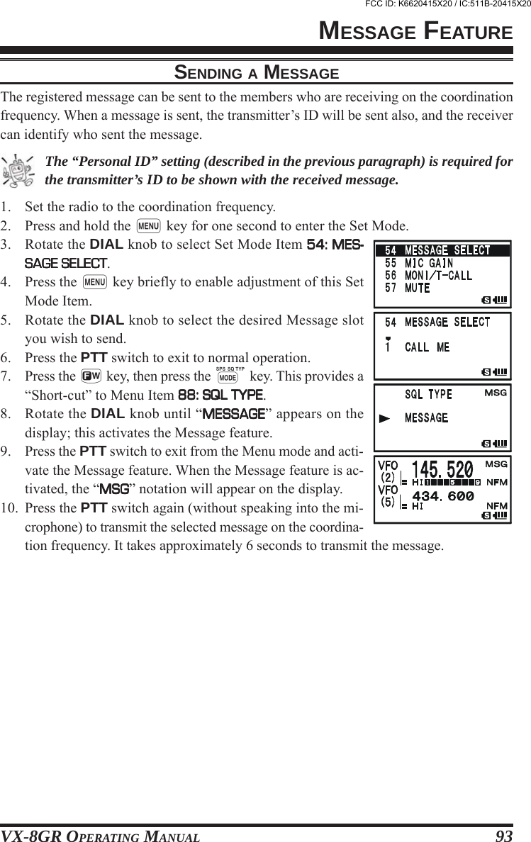
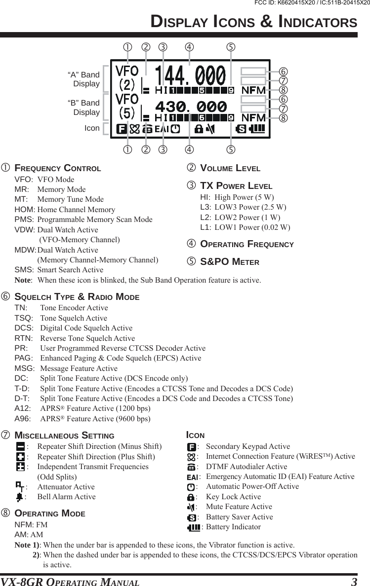
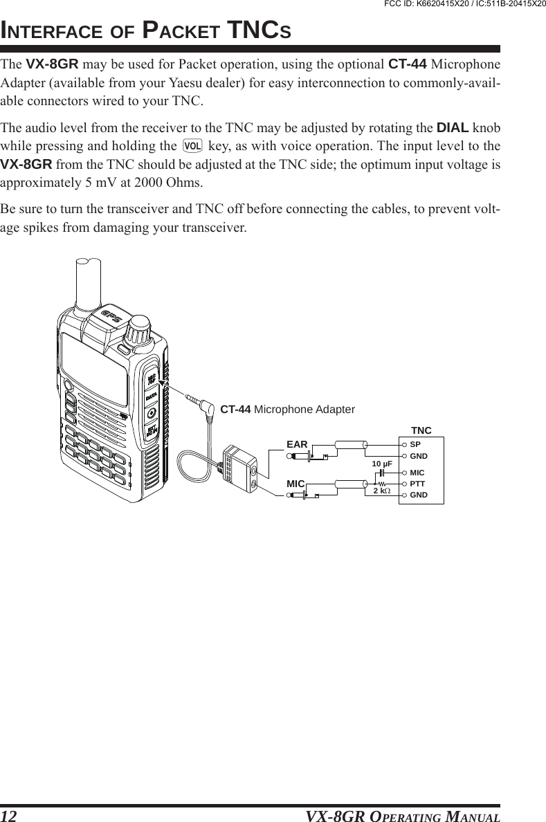
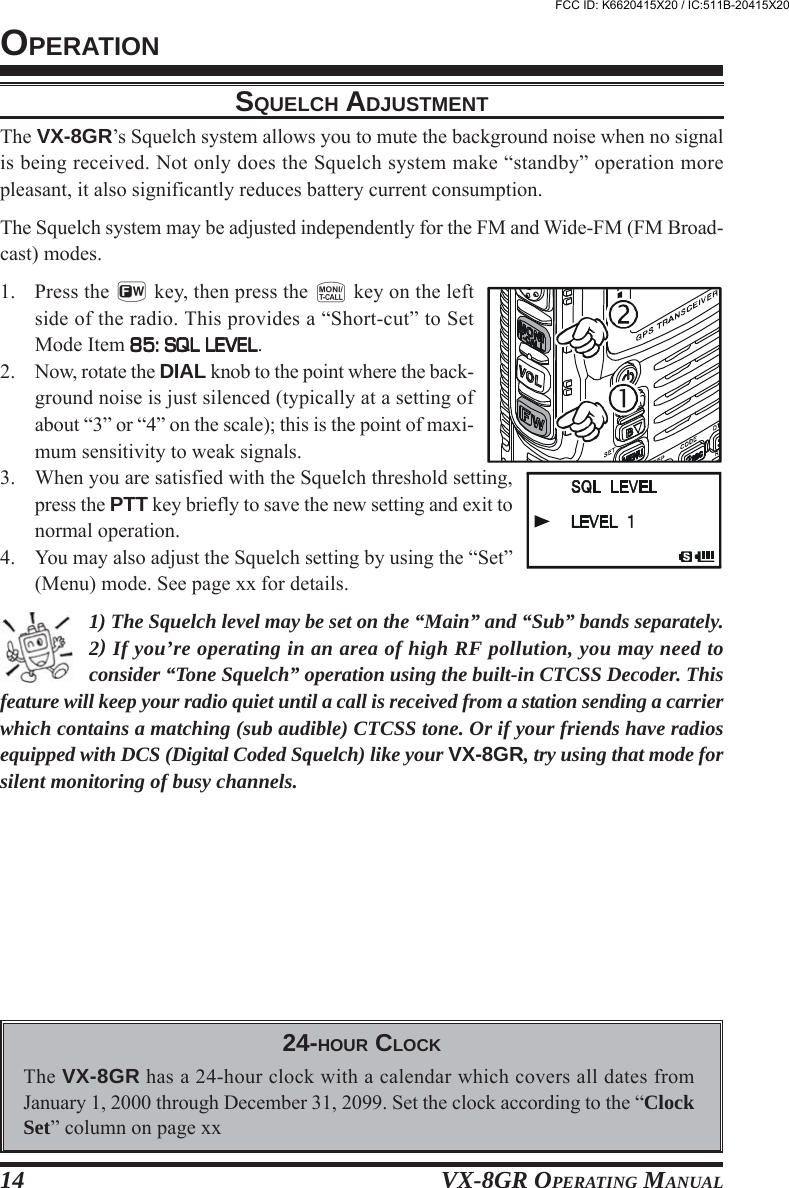
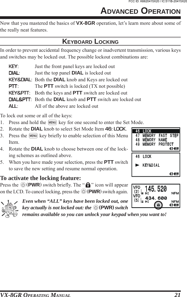
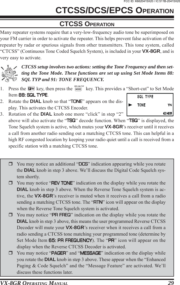
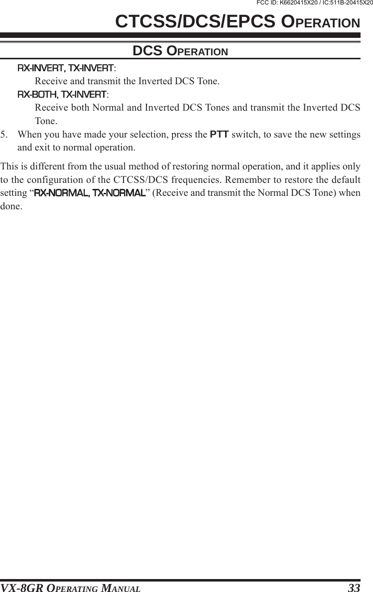
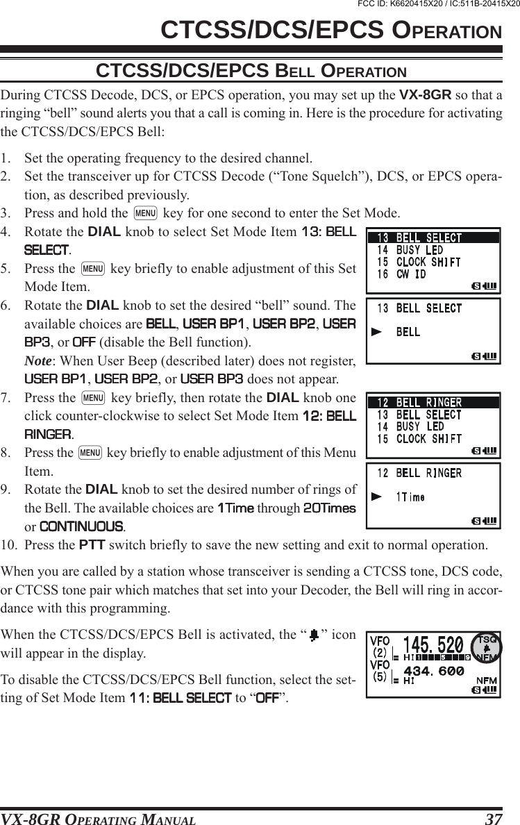
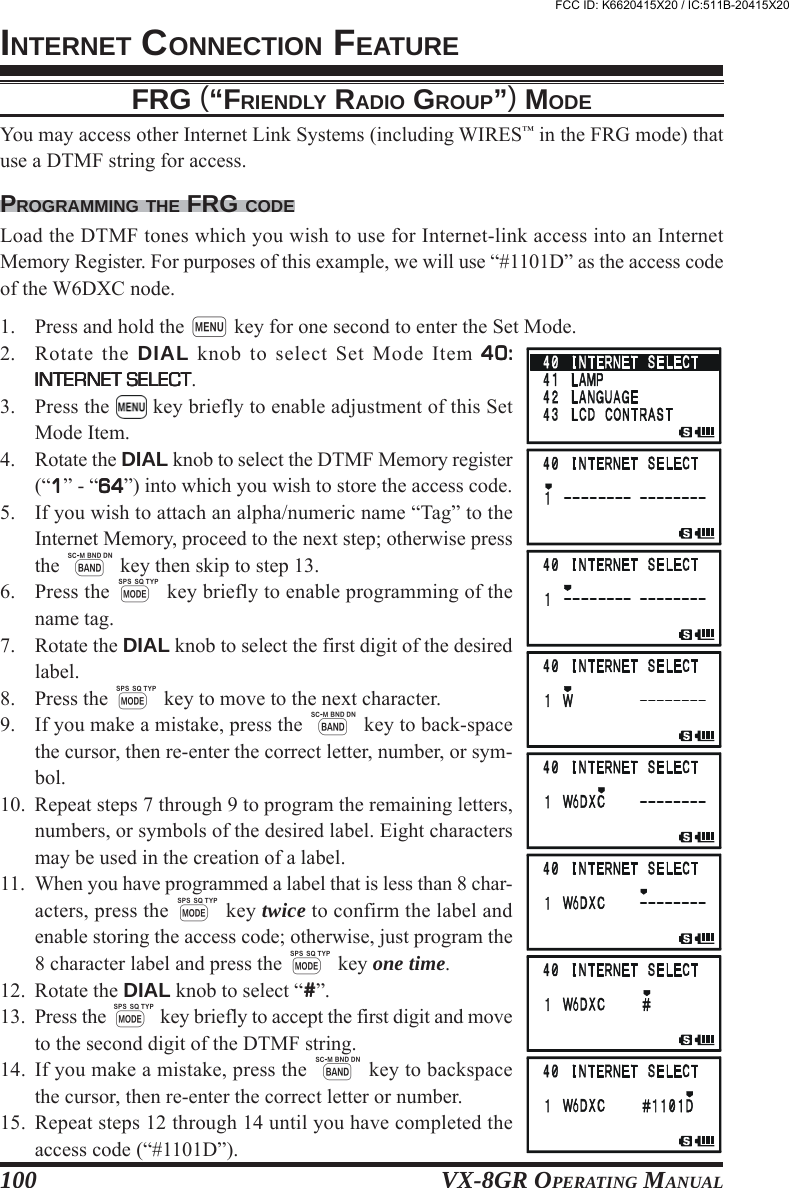
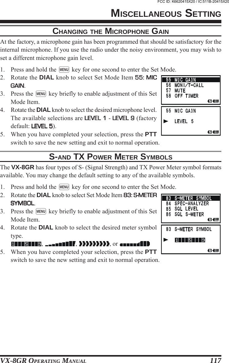
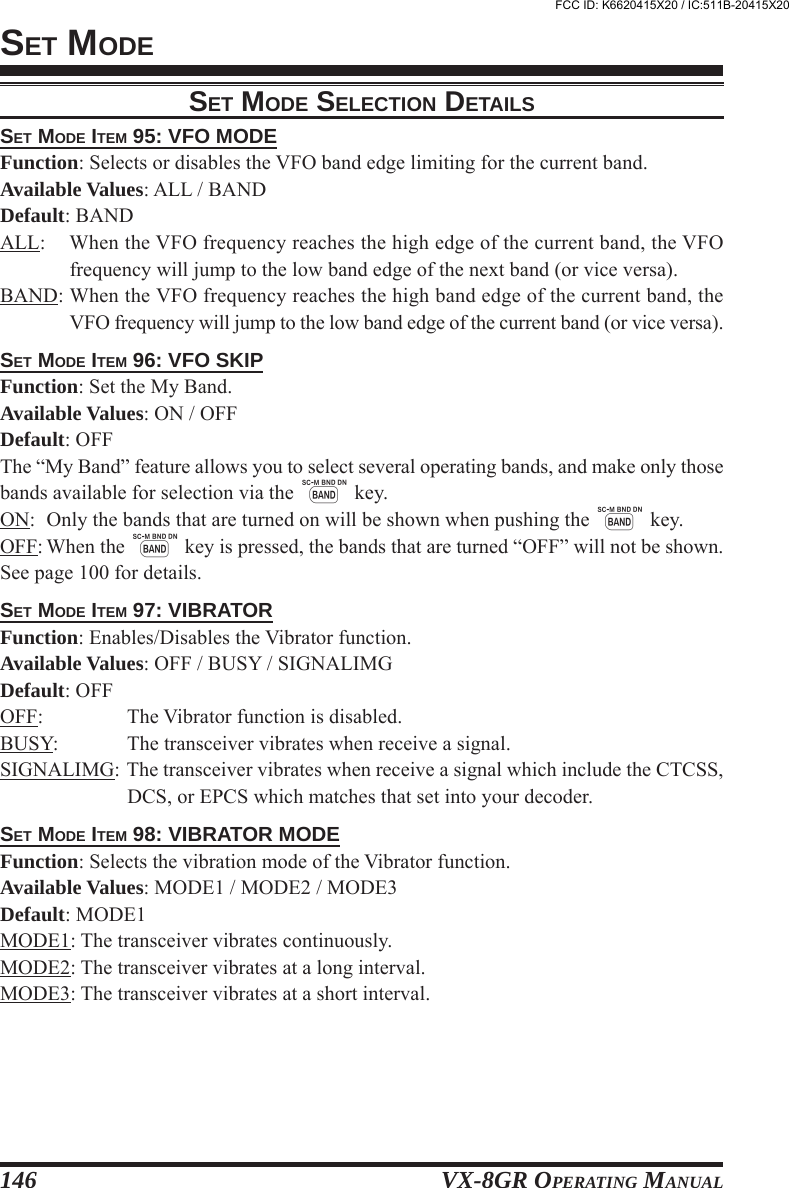
![VX-8GR OPERATING MANUAL94MESSAGE FEATURERECEIVING A MESSAGE1. Set the radio to the coordination frequency.2. Press the f key, then press the M key. This provides a“Short-cut” to Set Mode Item 88: SQL TYPE88: SQL TYPE88: SQL TYPE88: SQL TYPE88: SQL TYPE.3. Rotate the DIAL knob until “MESSAGEMESSAGEMESSAGEMESSAGEMESSAGE” appears on thedisplay; this activates the Message feature.4. Press the PTT switch to exit from the Set Mode and acti-vate the Message feature. When the Message feature is ac-tivated, the “MSGMSGMSGMSGMSG” notation will appear on the display.5. When you receive a message: a beep sounds, the LED lightblinks white, and [“Message” FROMFROMFROMFROMFROM “sending station’s ID”] scrolls on the display.6. Press any key (except g key) to clear the received message, and wait for a newmessage.To disable the Message feature, repeat the above procedure, rotating the DIAL knob toselect “OFFOFFOFFOFFOFF” in step 3 above.If you enable the CTCSS/DCS/EPCS Bell feature or CTCSS/DCS/EPCSVibrator Operation (described previously), you can tell that you are receiv-ing a message by the ringing “bell” sound alert or vibrating the transceiver.FCC ID: K6620415X20 / IC:511B-20415X20](https://usermanual.wiki/Yaesu-Musen/20415X20/User-Guide-1261125-Page-96.png)
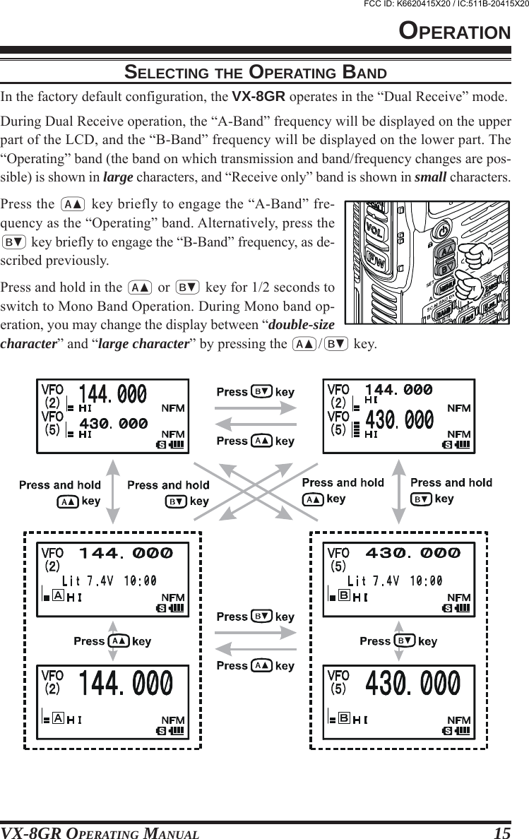
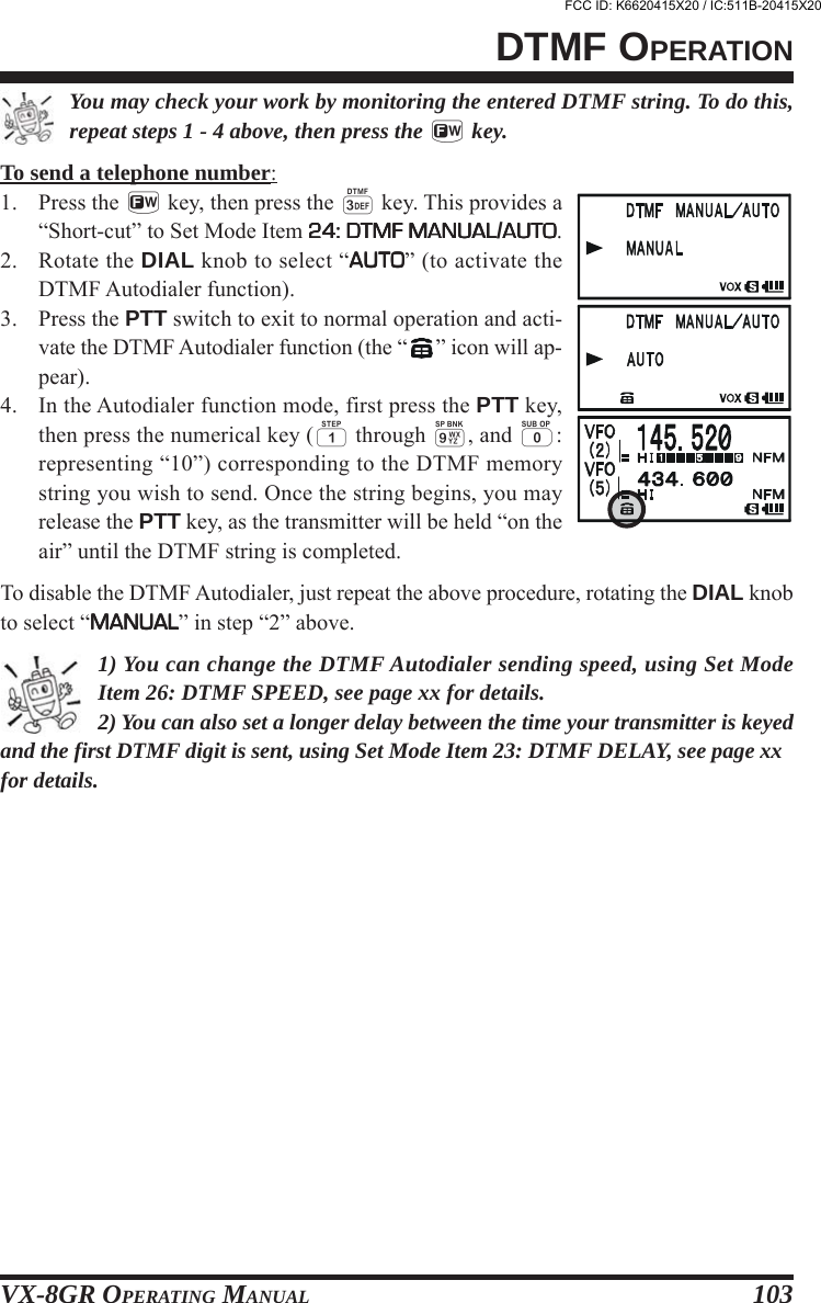
![VX-8GR OPERATING MANUAL102The VX-8GR’s keypad allows easy DTMF dialing for Autopatch, repeater control, orInternet-link access purposes. Besides numerical digits [0] through [9], the keypad in-cludes the [] and [#] digits, plus the [A], [B], [C], and [D] tones often used for repeatercontrol.MANUAL DTMF TONE GENERATIONYou can generate DTMF tones during transmission manually.1. Press the PTT switch to begin transmission.2. While transmitting, press the desired numbers on the keypad.3. When you have sent all the digits desired, release the PTT key.DTMF AUTODIALERNine DTMF Autodial memories are provided, allowing you to store telephone numbersfor autopatch use. You can also store short autopatch or Internet-link access code streamsto avoid having to send them manually.Here is the DTMF Autodial storage procedure:1. Press and hold the m key for one second to enter the Set Mode.2. Rotate the DIAL knob to select Set Mode Item 25: DTMF25: DTMF25: DTMF25: DTMF25: DTMFSELECTSELECTSELECTSELECTSELECT.3. Press the m key briefly to enable adjustment of this SetMode Item.4. Rotate the DIAL knob to select the DTMF Memory register(11111 - 1010101010) into which you wish to store this DTMF string.5. Press the M key briefly to begin DTMF Memory entryinto the selected register.6. Press and hold in the h key for two seconds to clear thepreviously-stored data, if desired.7. Rotate the DIAL knob to select the first digit of the DTMFstring. Selectable entries are 00000 - 99999, AAAAA - DDDDD, , and #####. Youmay select “–––––” to store a “Pause”, if needed.8. Press the M key to move to the next character.9. Repeats steps 7 and 8 to program the remaining the DTMFstring.10. Press and hold in the h key for two seconds to delete thepreviously-stored data after the cursor.11. If you make a mistake, press the B key to back-spacethe cursor, re-enter the correct number.12. Press the PTT switch briefly to save the new setting andexit to normal operation. To store other numbers, repeat thisprocess, using a different DTMF memory register.DTMF OPERATIONFCC ID: K6620415X20 / IC:511B-20415X20](https://usermanual.wiki/Yaesu-Musen/20415X20/User-Guide-1261125-Page-104.png)
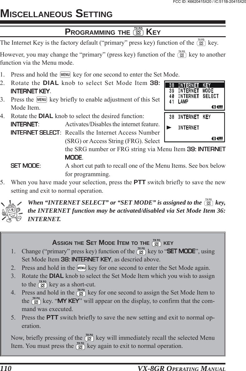
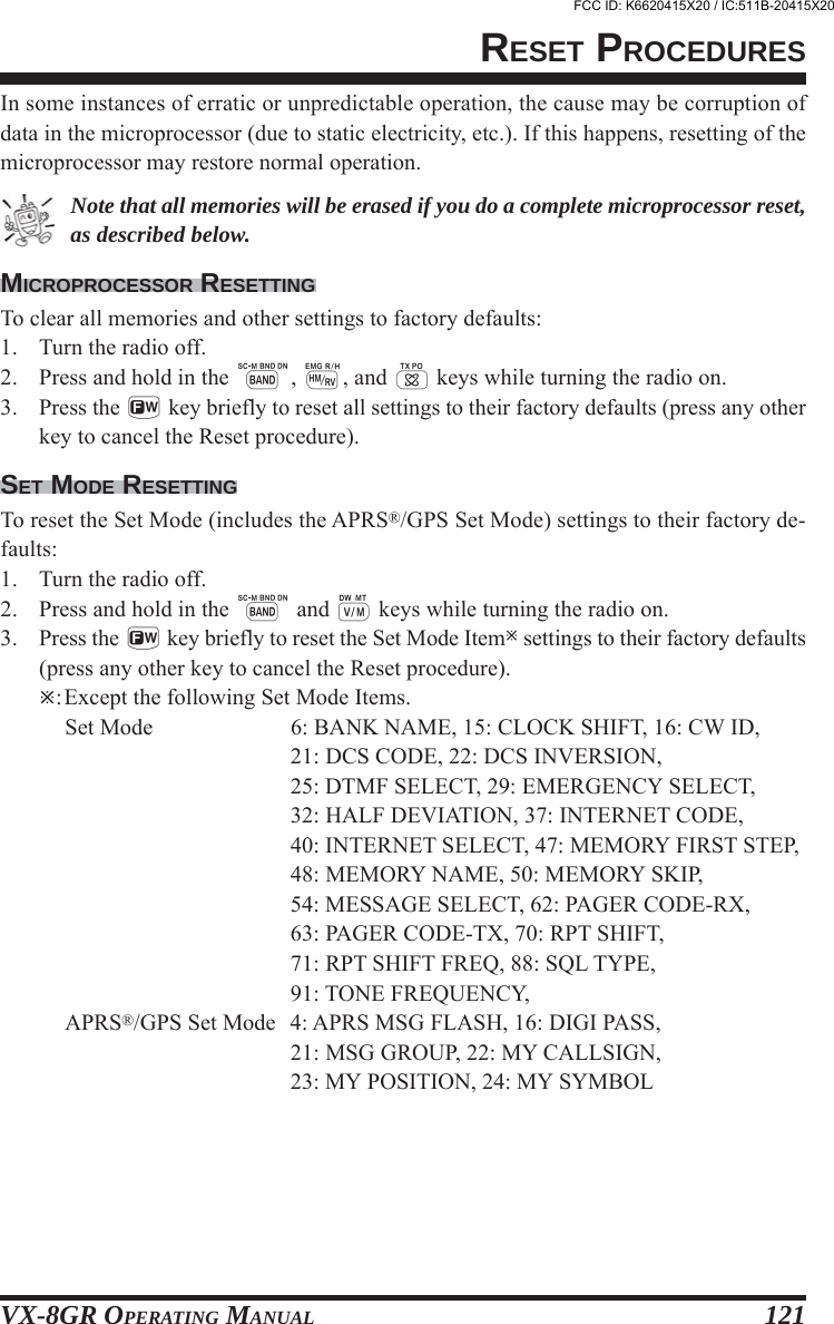
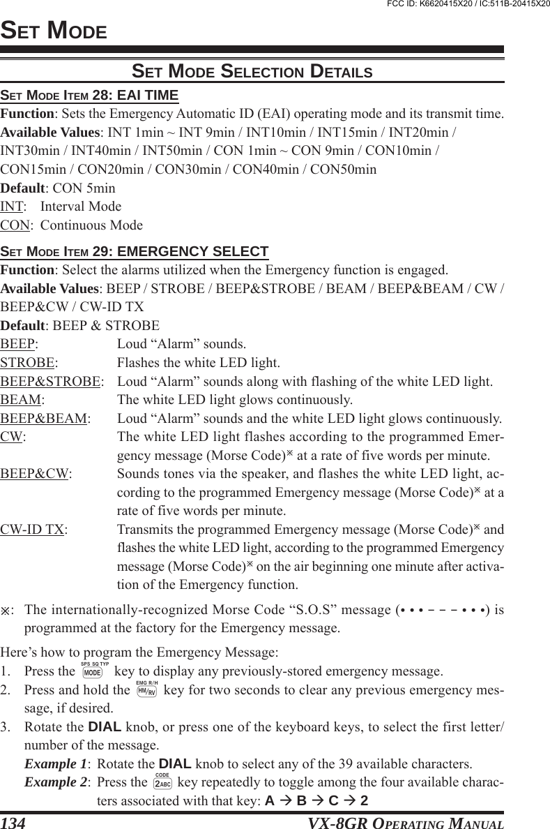
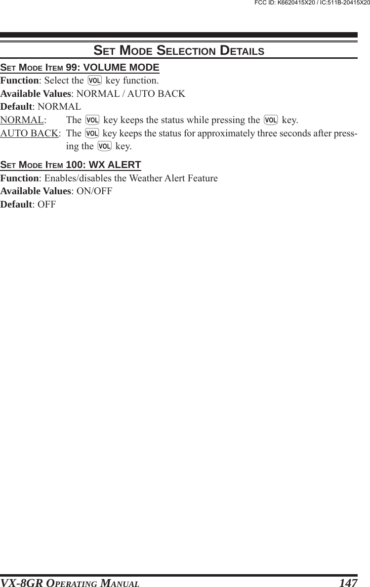
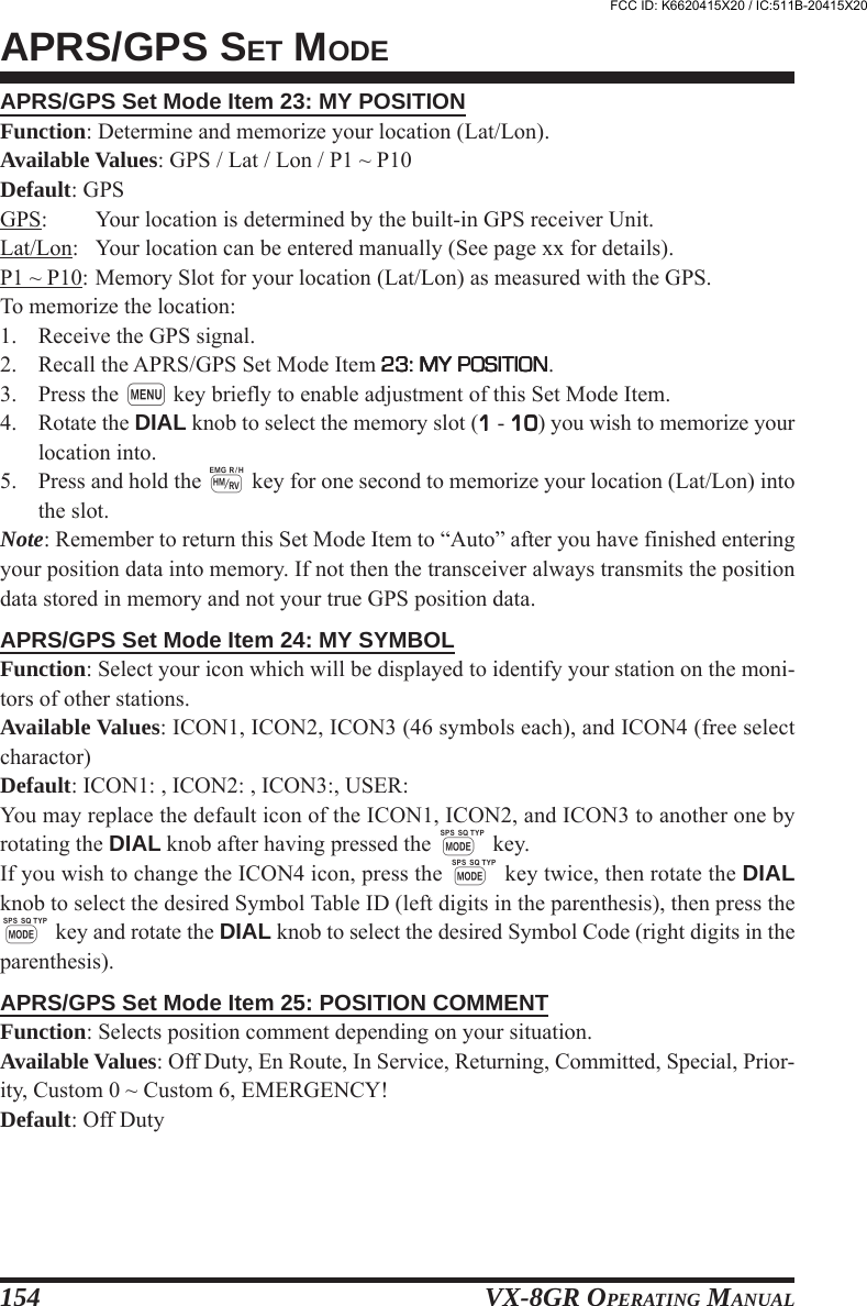
![VX-8GR OPERATING MANUAL1261: ANTENNA ATT2: APO3: ARTS BEEP4: ARTS INTERVAL5: BANK LINK6: BANK NAME7: BCLO8: BEEP EDGE9: BEEP LEVEL10: BEEP MELODY11: BEEP SELECT12: BELL RINGER13: BELL SELECT14: BUSY LED15: CLOCK SHIFT16: CW ID17: CW LEARNING18: CW PITCH19: CW TRAINING20: DC VOLTAGE21: DCS CODE22: DCS INVERSION23: DTMF DELAY24: DTMF MANUAL/AUTO25: DTMF SELECT26: DTMF SPEED27: EAI28: EAI TIME29: EMERGENCY SELECT30: EXTENDED MENU31: FW KEY HOLD TIME32: HALF DEVIATION33: HOME VFO34: HOME/REVERSE35: INT MANUAL/AUTO36: INTERNET37: INTERNET CODE38: INTERNET KEY39: INTERNET MODE40: INTERNET SELECT41: LAMP42: LANGUAGE43: LCD CONTRAST44: LCD DIMMER45: LED LIGHT46: LOCK47: MEMORY FAST STEP48: MEMORY NAME49: MEMORY PROTECTSET MODEEnables/Disables the receiver Front-end Attenuator.Setting of the Automatic Power-Off time.Select the Beep option during ARTSTM operation.Select the Polling Interval during ARTSTM operation.Enables/Disables the Memory Bank Link Scan.Stores Alpha-Numeric “Tag” for the Memory Bank.Enables/disables the Busy Channel Lock-Out feature.Enables/disables the Band-edge beeper while selecting the frequency by the DIAL knob.Adjust the Beep volume level.Create the Beep Melody for Bell ringer function.Enables/Disables the keypad beeper.Selects the number of Bell ringer repetitions.Enables/Disables the Bell ringer function and its sound selection.Enables/Disables the BUSY LED while the squelch is open.Shifting of CPU clock frequency.Program and activate the CW Identifier (used during ARTSTM operation).Enables/Disables the CW Learning feature.Select the CW tone pitch for the CW Learning, CW Training, and CW Identifier functions.Enables/Disables the CW Training feature.Indicates the DC Supply Voltage.Setting of the DCS code.Enables/Disables the “Inverted” DCS tone.Selects the DTMF Autodialer Delay Time.Enables/Disables the DTMF Autodial feature.Programming of the DTMF Autodialer.Selects the DTMF Autodialer Sending Speed.Enables/Disables the Emergency Automatic ID (EAI) feature.Sets the Emergency Automatic ID (EAI) operating mode and its transmit time.Select the alarms utilized when the Emergency function is engaged.Enables/Disables the extended Set Mode Menu.Set the duration that a secondary function of the [F/W] key (press and holding the [F/W] key)is held determines the function they activate.Reducing the Deviation level by 50 %.Enables/Disables the function of the VFO DIAL knob, while in the Home Channel mode.Selects the primary function of the [H/M] key (press the [H/M] key).Enables/Disables the DTMF Autodialer feature while operating using the Internet Connec-tion feature (WIRESTM).Enables/Disables the Internet Connection feature (WIRESTM).Selects the Access Number (DTMF digit) for the SRG operation of the Internet Connectionfeature (WIRESTM).Selects the primary function of the [INTERNET] key.Selects the operating mode of the Internet Connection feature (WIRESTM).Programming of the Access Number (DTMF code) for the FRG station of the WIRESTM (ornon WIRESTM Internet Link System) access.Selects the LCD/Keypad Lamp mode.Selects the language for the Set Mode selections.Setting of the Display contrast level.Setting of the Display brightness level.Illuminates the white LED light continuously (useful as emergency flashlight at night).Selects the Control Locking lockout combination.Selects the channel step for the fast channel selection mode while in the Memory Recallmode.Stores “Alpha-Numeric” tags for the Memory channels.Enables/Disables the Memory Write Protector.SET MODE ITEM FUNCTIONON / OFF0.5hour - 12.0hour / OFFIN RANGE / ALWAYS / OFF15sec / 25sec----ON / OFFON / OFFLEVEL 1 ~ LEVEL 9 (LEVEL 5)--KEY & SCAN / KEY / OFF1Time - 20Times / CONTINUOUSOFF / BELL /USER BP1 / USER BP2 / USER BP3ON / OFFON / OFF----400 - 1000 Hz (50 Hz/step) (700 Hz)----104 standard DCS codes (DCS 023)RX-NORMAL, TX-NORMAL /RX-INVERT, TX-NORMAL /RX-BOTH, TX-NORMAL /RX-NORMAL, TX-INVERT /RX-INVERT, TX-INVERT /RX-BOTH, TX-INVERT50ms / 250ms / 450ms / 750ms / 1000msMANUAL / AUTO--50ms / 100msON / OFFINT 1min ~ INT 9min / INT10min / INT15min /INT20min / INT30min / INT40min / INT50min /CON 1min ~ CON 9min / CON10min /CON15min / CON20min / CON30min /CON40min / CON50min (CON 5min)BEEP / STROBE / BEEP&STROBE /BEAM / BEEP&BEAM / CW / BEEP&CW /CW-ID TXON / OFFFW0.3sec / FW0.5sec / FW0.7sec /FW1.0sec / FW1.5secON / OFFDISABLE / ENABLEHOME / REVMANUAL / AUTOON / OFFDTMF 0 ~ DTMF 1, DTMF A ~ DTMF D,DTMF , DTMF # (DTMF 1)INTERNET / INTERNET SELECT /SET MODEFRG / SRG--KEY 2sec - KEY10sec / CONTINUOUS /OFF (KEY 5sec)ENGLISH / JAPANESELEVEL 12 ~ LEVEL32 (LEVEL24)LEVEL 1 ~ LEVEL 4--KEY / DIAL / KEY&DIAL / PTT / KEY&PTT /DIAL&PTT / ALL10CH / 20CH / 50CH / 100CH--ON / OFFAVAILABLE VALUES(DEFALT: BOLD ITALIC)FCC ID: K6620415X20 / IC:511B-20415X20](https://usermanual.wiki/Yaesu-Musen/20415X20/User-Guide-1261125-Page-128.png)
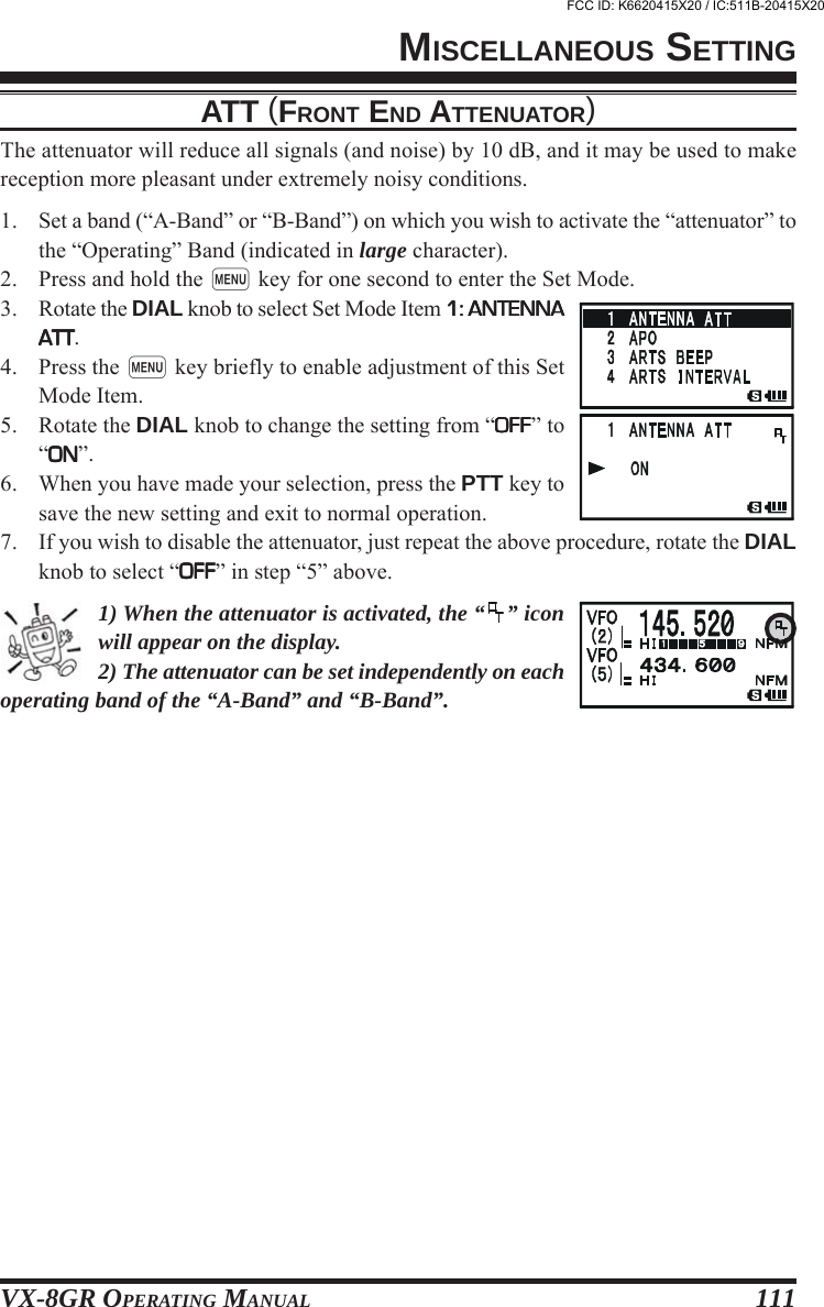
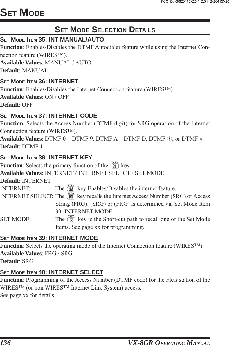
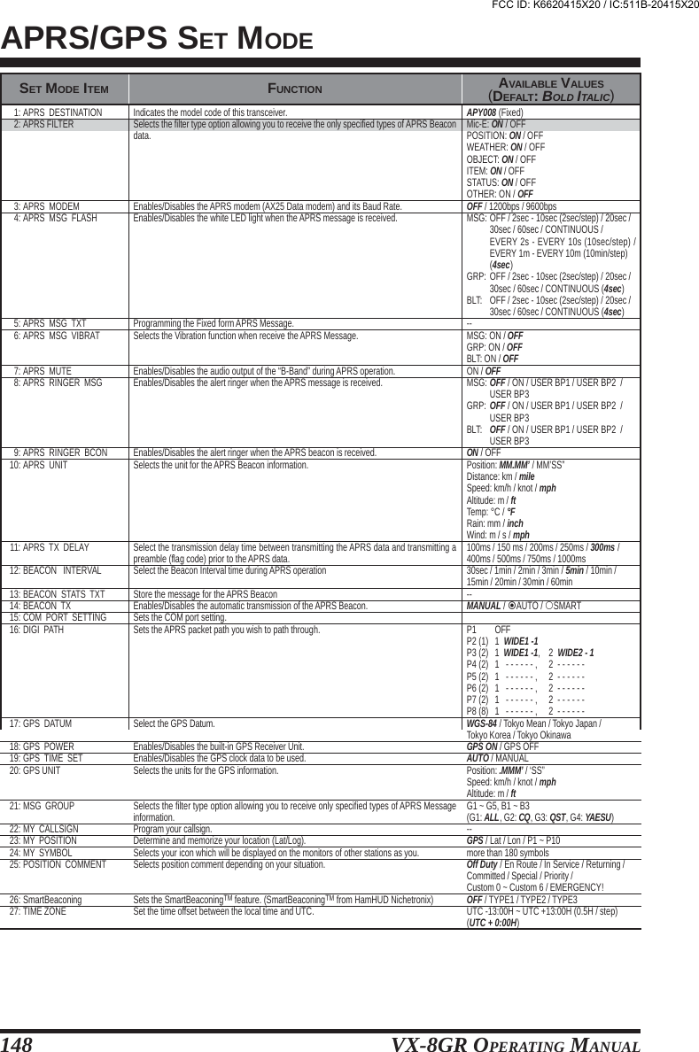
![VX-8GR OPERATING MANUAL 127SET MODE50: MEMORY SKIP51: MEMORY WRITE52: MESSAGE LIST53: MESSAGE REGISTER54: MESSAGE SELECT55: MIC GAIN56: MONI/T-CALL57: MUTE58: OFF TIMER59: ON TIMER60: OPENING MESSAGE61: PAGER ANS-BACK62: PAGER CODE-RX63: PAGER CODE-TX64: PASSWORD65: PR FREQUENCY66: PRI REVERT67: PRI TIME68: PTT DELAY69: RPT ARS70: RPT SHIFT71: RPT SHIFT FREQ72: RX MODE73: SAVE RX74: SAVE TX75: SCAN LAMP76: SCAN RE-START77: SCAN RESUME78: SENSOR DISPLAY79: SENSOR INFO80: SET MODE CSR81: SET MODE FORMAT82: SMART SEARCH83: S-METER SYMBOL84: SPEC-ANALYZER85: SQL LEVEL86: SQL S-METER87: SQL SPLIT88: SQL TYPE89: STEP FREQUENCY90: TIME SET91: TONE FREQUENCY92: TONE-SRCH MUTE93: TONE-SRCH SPEED94: TOT95: VFO MODE96: VFO SKIP97: VIBRATOR98: VIBRATOR MODE99: VOLUME MODE100: WX ALERTSelects the Memory Scan channel-selection mode.Determines the method of selecting channels for Memory Storage.Programming a Member List for the Message feature.Selects your Personal ID for the Message feature.Programming a Message for the Message feature.Adjusts the microphone gain level.Selects the MONI key (just below the PTT switch) function.Adjusts the receiver audio output level when the MUTE function was activated.Set the OFF Timer time.Set the ON Timer time.Selects the Opening Message that appears when the radio is powered on.Enables/Disables the Answer Back function of the Enhanced CTCSS Paging & Code Squelch.Sets the Receiver Pager Code for the Enhanced CTCSS Paging & Code Squelch.Sets the Transmitting Pager Code for the Enhanced CTCSS Paging & Code Squelch.Programming and activating the Password feature.Program the CTCSS Tone Frequency for the User Programmed Reverse CTCSS Decoder.Enables/Disables the Priority Revert feature.Selects the time between the Priority (Dual Watch) channel checks, when the feature isactive.Selects the time delay before the carrier is transmitted, when the PTT switch is pressed.Enables/Disables the Automatic Repeater Shift function.Sets the Repeater Shift Direction.Sets the magnitude of the Repeater Shift.Sets the receiving mode.Selects the Receive-mode Battery Saver interval (“sleep” ratio).Enables/Disables the Transmitter Battery Saver.Enables/Disables the Scan Lamp (while scanner is paused).Selects the Scan Re-start Delay time.Selects the Scan Resume mode.Selects the sensor information when the transceiver is operating in the “Mono” band modewith large characters.Indicates the Information of the internal sensors.Selects the Set Mode Cursor.Selects the display format of the Set Mode operation.Selects the Smart Search Sweep mode.Selects the S- & TX PO meter Symbol.Selects the Spectrum Analyzer sweep mode.Sets the Squelch threshold level.Adjusts the Squelch threshold level to the S-meter level.Enables/disables split CTCSS/DCS coding.Selects the Tone Encoder and/or Decoder mode.Setting of the DIAL frequency steps.Sets the Clock time.Setting of the CTCSS Tone FrequencyEnables/Disables the receiver audio output while the Tone Search Scanner is activated.Selects the Tone Search Scanner speed.Setting of the TOT timeSelects or disables the VFO band edge limiting for the current band.Setting My Band.Enables/Disables the Vibrator function.Selects the vibration mode of the Vibrator function.Select the [VOL] key function.Enables/Disables the Weather Alert FeatureOFF / SKIP / ONLYNEXT / LOWER------LEVEL 1 ~ LEVEL 9 (LEVEL 5)MONI / T-CALL1MUTE 30%, MUTE 50%,MUTE 100%, or OFF----NORMAL / OFF / DC / MESSAGEON / OFF------300Hz ~ 3000Hz (1000Hz/step) (1600Hz)ON / OFF0.1sec ~ 0.9sec (0.1sec/step) or1.0sec ~ 10.0sec (0.5sec/step) (5.0sec)OFF / 20ms / 50ms / 100ms / 200msON / OFFSIMPLEX / -RPT / +RPT0.000MHz ~ 150.000MHz (50 kHz/step)2AUTO / NFM / AM0.2sec ~ 0.9sec (0.1sec/step),1.0sec ~ 9.5sec (0.5sec/step), or10.0sec ~ 60.0sec (5sec/step)ON / OFFON / OFF0.1sec ~ 0.9sec (0.1sec/step) or1.0sec ~ 10.0sec (0.5sec/step) (2.0sec)2.0sec ~ 10.0sec (0.5sec/step) /BUSY /HOLD (5.0sec)DC / TEMP / WAVE / BARO / ALTI / OFF--Nine patternsLIST / ITEMSINGLE / CONTINUOUSFour patterns1Time / CONTINUOUS / Full TimeLEVEL 0 ~ LEVEL 15 (LEVEL 1)OFF / LEVEL 0 ~ LEVEL 9OFF / ONOFF / TONE / TONE SQL / DCS /REV TONE / PR FREQ / PAGER / MESSAGEAUTO / 5.0 / 6.25 / 8.33 / 9.0 / 10.0 / 12.5 /15.0 / 20.0 / 25.0 / 50.0 / 100.0 kHz--50 standard CTCSS tones (100.0Hz)ON / OFFFAST (2.5 tone/sec) / SLOW (1.25 tone/sec)OFF / 0.5min ~ 10.0min (0.5min/step)(3.0min)ALL / BAND--OFF / BUSY / SIGNALINGMODE1 / MODE2 / MODE3NORMAL / AUTO BACKON / OFFSET MODE ITEM FUNCTION AVAILABLE VALUES(DEFALT: UNDERLINED BOLD)1: Depends on the transceiver version.2: Depends on the operating band and transceiver version.FCC ID: K6620415X20 / IC:511B-20415X20](https://usermanual.wiki/Yaesu-Musen/20415X20/User-Guide-1261125-Page-129.png)
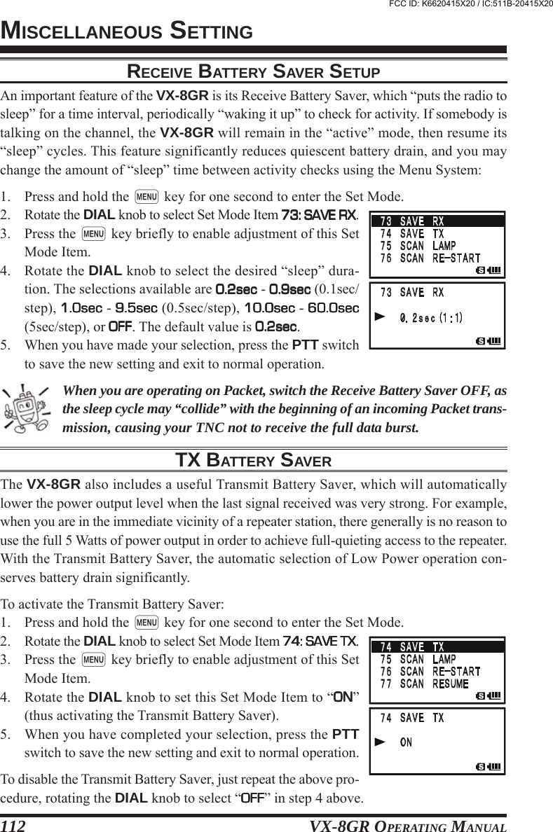
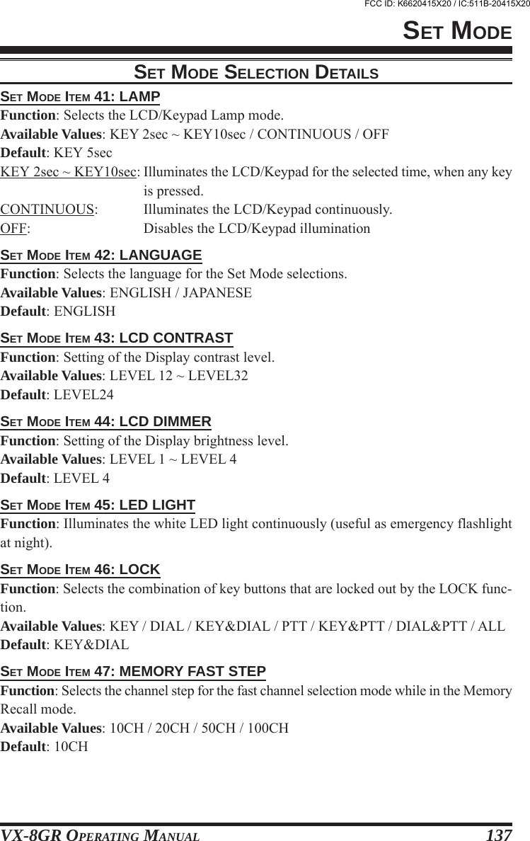
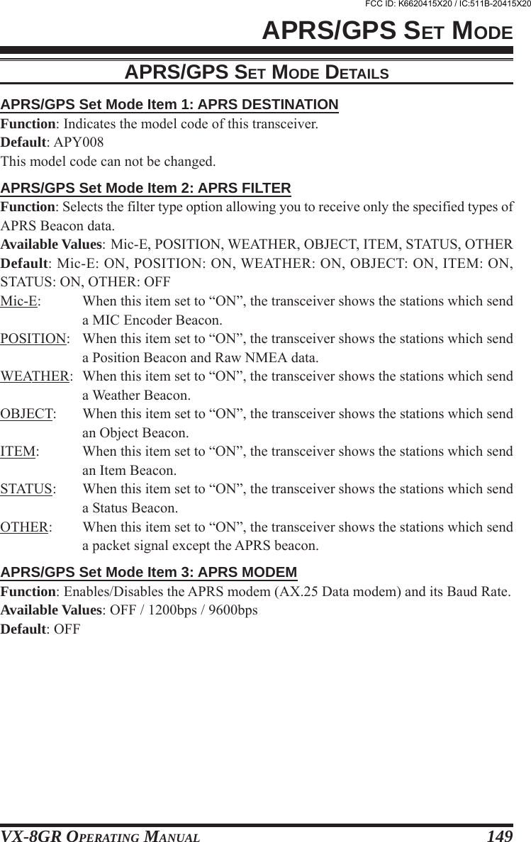
![VX-8GR OPERATING MANUAL128SET MODEREPEATER SETTINGEnables/Disables the Automatic Repeater Shift function.Sets the Repeater Shift Direction.Sets the magnitude of the Repeater Shift.CTCSS/DCS/EPCS SETTINGSelects the number of Bell ringer repetitions.Enables/Disables the Bell ringer function and its sound selection.Setting of the DCS code.Enables/Disables the “Inverted” DCS tone.Enables/Disables the Answer Back function of the Enhanced CTCSS Paging & Code Squelch.Sets the Receiver Pager Code for the Enhanced CTCSS Paging & Code Squelch.Sets the Transmitting Pager Code for the Enhanced CTCSS Paging & Code Squelch.Program the CTCSS Tone Frequency for the User Programmed Reverse CTCSS Decoder.Enables/Disables split CTCSS/DCS coding.Selects the Tone Encoder and/or Decoder mode.Setting of the CTCSS Tone FrequencyEnables/Disables the receiver audio output while the Tone Search Scanner is activated.Selects the Tone Search Scanner speed.ARTSTM SETTINGSelect the Beep option during ARTSTM operation.Select the Polling Interval during ARTSTM operation.Program and activate the CW Identifier (used during ARTSTM operation).MEMORY SETTINGEnables/Disables the Memory Bank Link Scan.Stores Alpha-Numeric “Tag” for the Memory Bank.Selects the channel step for the fast channel selection mode while in the Memory Recall mode.Stores “Alpha-Numeric” tags for the Memory channels.Enables/Disables the Memory Write Protector.Determines the method of selecting channels for Memory Storage.SCAN SETTINGSelects the Memory Scan channel-selection mode.Enables/Disables the Scan Lamp (while scanner is paused).Selects the Scan Re-start Delay time.Selects the Receive-mode Battery Saver interval (“sleep” ratio).Enables/Disables the Priority Revert feature.Selects the time between the Priority (Dual Watch) channel checks, when the feature is active.BATTERY SAVING SETTINGSetting of the Automatic Power-Off time.Enables/Disables the BUSY LED while the squelch is open.Selects the Receive-mode Battery Saver interval (“sleep” ratio).Enables/Disables the Transmitter Battery Saver.MESSAGE SETTINGProgramming a Member List for the Message feature.Selects your Personal ID for the Message feature.Programming a Message for the Message feature.WIRESTM SETTINGEnables/Disables the DTMF Autodialer feature while using the Internet Connection feature (WIRESTM).Enables/Disables the Internet Connection feature (WIRESTM).Selects the Access Number (DTMF digit) for SRG operation of the Internet Connection feature (WIRESTM).Selects the primary function of the [INTERNET] key.Selects the operating mode of the Internet Connection feature (WIRESTM).Programming of the Access Number (DTMF code) for the FRG station of the WIRESTM (or non WIRESTMInternet Link System) access.EAI SETTINGEnables/Disables the Emergency Automatic ID (EAI) feature.Sets the Emergency Automatic ID (EAI) operating mode and its transmit time.Select the alarms utilized when the Emergency function is engaged.SET69:70:71:SET12:13:21:22:61:62:63:65:87:88:91:92:93:SET3:4:16:SET5:6:47:48:49:51:SET50:75:76:77:66:67:SET2:14:73:74:SET52:53:54:SET35:36:37:38:39:40:SET27:28:29: MODE ITEMRPT ARSRPT SHIFTRPT SHIFT FREQ MODE ITEMBELL RINGERBELL SELECTDCS CODEDCS INVERSIONPAGER ANS-BACKPAGER CODE-RXPAGER CODE-TXPR FREQUENCYSQL SPLITSQL TYPETONE FREQUENCYTONE-SRCH MUTETONE-SRCH SPEED MODE ITEMARTS BEEPARTS INTERVALCW ID MODE ITEMBANK LINKBANK NAMEMEMORY FAST STEPMEMORY NAMEMEMORY PROTECTMEMORY WRITE MODE ITEMMEMORY SKIPSCAN LAMPSCAN RE-STARTSCAN RESUMEPRI REVERTPRI TIME MODE ITEMAPOBUSY LEDSAVE RXSAVE TX MODE ITEMMESSAGE LISTMESSAGE REGISTERMESSAGE SELECT MODE ITEMINT MANUAL/AUTOINTERNETINTERNET CODEINTERNET KEYINTERNET MODEINTERNET SELECT MODE ITEMEAIEAI TIMEEMERGENCY SELECTAVAILABLE VALUES (DEFAULT: BOLD ITALIC)ON / OFFSIMPLEX / -RPT / +RPT0.000MHz ~ 150.000MHz (50 kHz/step)1AVAILABLE VALUES (DEFAULT: BOLD ITALIC)1time - 20times / CONTINUOUSOFF / BELL / USER BP1 / USER BP2 /USER BP3104 standard DCS codes (DCS 023)RX-NORMAL, TX-NORMAL /RX-INVERT, TX-NORMAL /RX-BOTH, TX-NORMAL /RX-NORMAL, TX-INVERT /RX-INVERT, TX-INVERT / RX-BOTH, TX-INVERTON / OFF----300 Hz ~ 3000 Hz (1000 Hz/step) (1600 Hz)OFF / ONOFF / TONE / TONE SQL / DCS / REV TONE /PR FREQ / PAGER / MESSAGE50 standard CTCSS tones (100.0Hz)ON / OFFFAST (2.5 tone/sec) / SLOW (1.25 tone/sec)AVAILABLE VALUES (DEFAULT: BOLD ITALIC)IN RANGE / ALWAYS / OFF15sec / 25sec--AVAILABLE VALUES (DEFAULT: BOLD ITALIC)----10CH / 20CH / 50CH / 100CH--ON / OFFNEXT / LOWERAVAILABLE VALUES (DEFAULT: BOLD ITALIC)OFF / SKIP / ONLYON / OFF0.1sec ~ 0.9sec (0.1sec/step) or1.0sec ~ 10.0sec (0.5sec/step) (5.0sec)2.0sec ~ 10.0sec (0.5sec/step) /BUSY / HOLD (5.0sec)ON / OFF0.1sec ~ 0.9sec (0.1sec/step) or1.0sec ~ 10.0sec (0.5sec/step) (5.0sec)AVAILABLE VALUES (DEFAULT: BOLD ITALIC)0.5hour - 12.0hour / OFFON / OFF0.2sec ~ 0.9sec (0.1sec/step),1.0sec ~ 9.5sec (0.5sec/step), or10.0sec ~ 60.0sec (5sec/step)ON / OFFAVAILABLE VALUES (DEFAULT: BOLD ITALIC)------AVAILABLE VALUES (DEFAULT: BOLD ITALIC)MANUAL / AUTOON / OFFDTMF 0 ~ DTMF 9, DTMF A ~ DTMF D, DTMF ,or DTMF # (DTMF 1)INTERNET / INT SELECT / SET MODEFRG / SRG--AVAILABLE VALUES (DEFAULT: BOLD ITALIC)ON / OFFINT 1min ~ INT 9min, INT10min, INT15min,INT20min, INT30min, INT40min, INT50min,CON 1min ~ CON 9min, CON10min, CON15min,CON20min, CON30min, CON40min, CON50min,(CON 5min)BEEP / STROBE / BEEP & STROBE / BEAM /BEEP & BEAM / CW / BEEP & CW / CW-ID TXFCC ID: K6620415X20 / IC:511B-20415X20](https://usermanual.wiki/Yaesu-Musen/20415X20/User-Guide-1261125-Page-130.png)
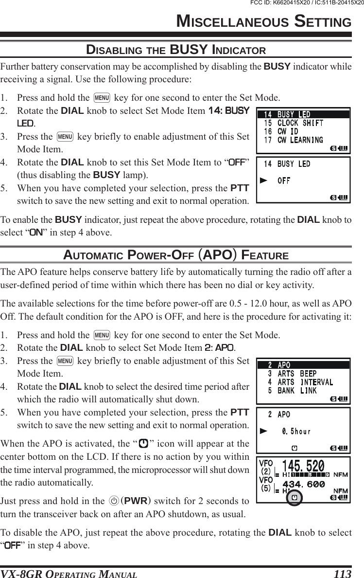
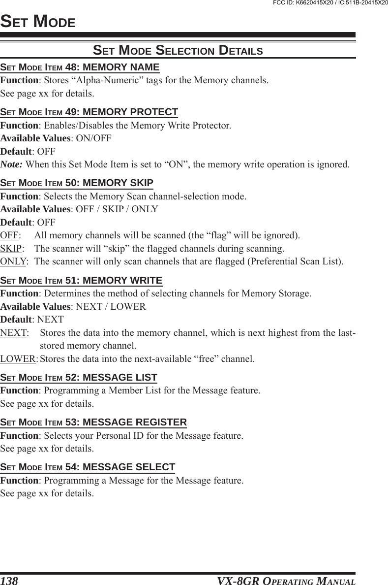
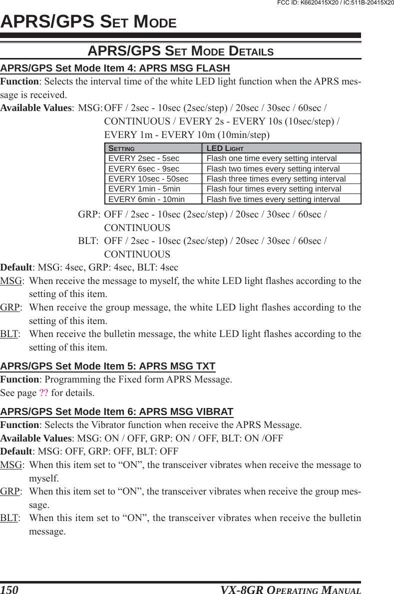
![VX-8GR OPERATING MANUAL 129SET MODEVIBRATOR SETTINGEnables/Disables the Vibrator function.Selects the vibration mode of the Vibrator function.DTMF SETTINGSelects the DTMF Autodialer Delay Time.Enables/Disables the DTMF Autodial feature.Programming the DTMF Autodialer.Selects the DTMF Autodialer Sending Speed.SWITCH/KNOB SETTINGSet the duration that a secondary function of the [F/W] key (press and holding the [F/W] key) is helddetermines the function they activate.Selects the function of the [H/M] key.Selects the Control Locking lockout combination.Selects the MONI key (just below the PTT switch) function.Selects the time delay before the carrier is transmitted, when the PTT switch is pressed.Select the [VOL] key function.DISPLAY SETTINGIndicates the DC Supply Voltage.Selects the LCD/Keypad Lamp mode.Setting the Display contrast level.Setting the Display brightness level.Illuminates the white LED light continuously (useful as emergency flashlight at night).Selects the Opening Message that appears when the radio is powered on.Selects the sensor information when the transceiver is operating in the “Mono” band mode with largecharacter.Displays internal sensor information.Selects the S- & TX PO meter Symbol.Selects the Spectrum Analyzer sweep mode.BEEP SETTINGEnables/Disables the Band-edge beeper while selecting the frequency with the DIAL knob.Adjust the Beep volume level.Create the Beep Melody for Bell ringer function.Enables/Disables the keypad beeper.Select the CW tone pitch for the CW Learning, CW Training, and CW Identifier functions.MISCELLANEOUS SETTINGEnables/Disables the receiver Front-end Attenuator.Enables/Disables the Busy Channel Lock-Out feature.Shifting of CPU clock frequency.Enables/Disables the CW Learning feature.Enables/Disables the CW Training feature.Enables/Disables the extended Set Mode Menu.Reducing the Deviation level by 50 %.Enables/Disables the function of the VFO DIAL knob, while in the Home Channel mode.Selects the language for the Set Mode selections.Adjusts the microphone gain level.Adjusts the receiver audio output level when the MUTE function was activated.Set the OFF Timer time.Set the ON Timer time.Programming and activating the Password feature.Sets the receiving mode.Selects the Set Mode Cursor.Selects the display format of the Set Mode operation.Selects the Smart Search Sweep mode.Sets the Squelch threshold level.Adjusts the Squelch threshold level to the S-meter level.Setting of the DIAL frequency steps.Sets the Clock time.Setting of the TOT timeSelects or disables the VFO band edge limiting for the current band.Set My Band.Enables/Disables the Weather Alert FeatureSET97:98:SET23:24:25:26:SET31:34:46:56:68:99:SET20:41:43:44:45:60:78:79:83:84:SET8:9:10:11:18:SET1:7:15:17:19:30:32:33:42:55:57:58:59:64:72:80:81:82:886:89:90:95:96:97:100: MODE ITEMVIBRATORVIBRATOR MODE MODE ITEMDTMF DELAYDTMF MANUAL/AUTODTMF SELECTDTMF SPEED MODE ITEMFW KEY HOLD TIMEHOME/REVERSELOCKMONI/T-CALLPTT DELAYVOLUME MODE MODE ITEMDC VOLTAGELAMPLCD CONTRASTLCD DIMMERLED LIGHTOPENING MESSAGESENSOR DISPLAYSENSOR INFORMATIONS-METER SYMBOLSPEC-ANALYZER MODE ITEMBEEP EDGEBEEP LEVELBEEP MELODYBEEP SELECTCW PITCH MODE ITEMANTENNA ATTBCLOCLOCK SHIFTCW LEARNINGCW TRAININGEXTENDED MENUHALF DEVIATIONHOME VFOLANGUAGEMIC GAINMUTEOFF TIMERON TIMERPASSWORDRX MODESET MODE CSRSET MODE FORMATSMART SEARCHSQL LEVELSQL S-METERSTEP FREQUENCYTIME SETTOTVFO MODEVFO SKIPWX ALERTAVAILABLE VALUES (DEFAULT: BOLD ITALIC)OFF / BUSY / SIGNALINGMODE1 / MODE2 / MODE3AVAILABLE VALUES (DEFAULT: BOLD ITALIC)50ms / 250ms / 450ms / 750ms / 1000msMANUAL / AUTO--50mS / 100mSAVAILABLE VALUES (DEFAULT: BOLD ITALIC)0.3sec / 0.5sec / 0.7sec / 1.0sec / 1.5secHOME / REVKEY / DIAL / KEY&DIAL / PTT / KEY&PTT /DIAL&PTT / ALLMONI / T-CALL2OFF / 20ms / 50ms / 100ms / 200msNORMAL / AUTO BACKAVAILABLE VALUES (DEFAULT: BOLD ITALIC)--KEY 2sec - KEY 10sec / CONTINUOUS /OFF (KEY 5sec)LEVEL 12 ~ LEVEL32 (LEVEL24)LEVEL 1 ~ LEVEL 4--NORMAL / OFF / DC / MESSAGEDC / TEMP / WAVE / BARO / ALTI / WX / OFF--Four patterns1Time / Continuous / Full TimeAVAILABLE VALUES (DEFAULT: BOLD ITALIC)ON / OFFLEVEL 1 - LEVEL 9 (LEVEL 5)--KEY & SCAN / KEY / OFF400 - 1000 Hz (50 Hz/step) (700 Hz)AVAILABLE VALUES (DEFAULT: BOLD ITALIC)ON / OFFON / OFFON / OFF----ON / OFFON / OFFDISABLE / ENABLEENGLISH / JAPANESELEVEL 1 ~ LEVEL 9 (LEVEL 5)MUTE 30%,MUTE 50%, MUTE 100%, or OFF------AUTO / NFM / AM / WFMNine patternsLIST / ITEMSINGLE / CONTINUOUSLEVEL 0 ~ LEVEL 15 (LEVEL 1)OFF / LEVEL 0 ~ LEVEL 9AUTO / 5.0 /6.25 / 8.33 / 9.0 / 10.0 / 12.5 / 15.0 /20.0 / 25.0 / 50.0 / 100 kHz--OFF / 0.5min ~ 10.0min (0.5min/step) (3.0min)ALL / BAND--ON / OFF1: Depends on the operating band and transceiver version.2: Depends on the transceiver version.FCC ID: K6620415X20 / IC:511B-20415X20](https://usermanual.wiki/Yaesu-Musen/20415X20/User-Guide-1261125-Page-131.png)

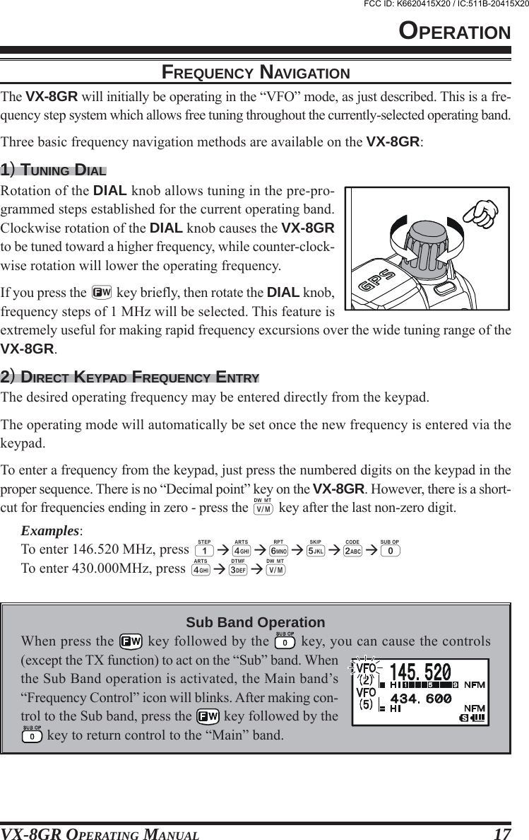
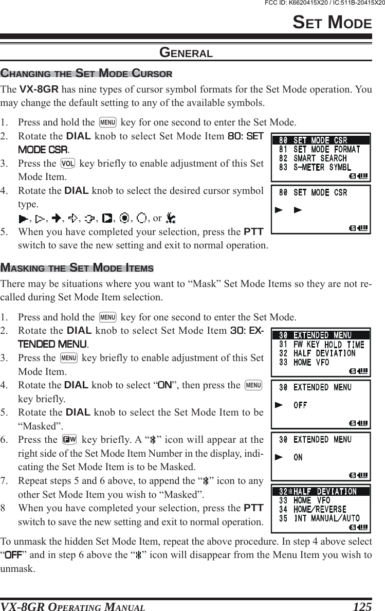
![VX-8GR OPERATING MANUAL158SPECIFICATIONSGENERALFrequency Ranges: A (Main) Band RX: 108-137 MHz (Air Band)137-174 MHz (144 MHz HAM)174-222 MHz (VHF-TV)222-420 MHz (General 1)420-470 MHz (430 MHz HAM)470-800 MHz (UHF-TV, Cellular Blocked)800-999.90 MHz (General 2, Cellular Blocked)B (Sub) Band RX: 108-137 MHz (Air Band)137-174 MHz (144 MHz HAM)174-222 MHz (VHF-TV)222-420 MHz (General 1)420-470 MHz (430 MHz HAM)470-580 MHz (UHF-TV)TX: 144-146 MHz or 144-148 MHz430-440 MHz or 430-450 MHzChannel Steps: 5/6.25/8.33/10/12.5/15/20/25/50/100 kHzEmission Type: F1D, F2A, F2D, F3EFrequency Stability: ±5 ppm (–10 °C to +60 °C [+14 °F to +140 °F])Repeater Shift: ±600 kHz (144 MHz), ±1.6/5.0/7.6 MHz (430 MHz)Antenna Impedance: 50 OhmsSupply Voltage: Nominal: 7.4 V DC (Negative Ground)Operating: 4-14 V DC (Negative Ground, EXT DC jack)Operating with Charging: 11-16 V DC (Negative Ground, EXT DC jack)Current Consumption: 200 mA (Mono Band Receive)(@7.4 VDC, approx.) 240 mA (Dual Band Receive)85 mA (Mono Band Receive, Standby, Saver Off)120 mA (Dual Band Receive, Standby, Saver Off)35 mA (Mono Band Receive, Standby, Saver On “Save Ratio 1:5”)42 mA (Dual Band Receive, Standby, Saver On “Save Ratio 1:5”)300 μA (Auto Power Off)1.7A (144 MHz, 5W TX)1.9 A (430 MHz, 5W TX)Operating Temperature: –20 °C to +60 °C (–4 °F to +140 °F)Case Size (W x H x D): 60 x 95 x 28 mm (2.4” x 3.7” x 1.1”) w/o knob & antennaWeight (Approx.): 250 g (8.8 oz) with FNB-101LI & antennaTRANSMITTERRF Power Output: 1.0 W (@4.5 V: AA x 3)5.0 W (@7.4 V or EXT DC)L3: 2.5 W, L2: 1 W, L1: 0.05 W (@7.4 V)Modulation Type: F2E, F3E: Variable ReactanceMaximum Deviation: ±5 kHz (F2E/F3E)Spurious Emission: At least 60 dB below (@ TX power HI/L3/L2)At least 50 dB below (@ TX power L1)Microphone Impedance: 2K OhmsFCC ID: K6620415X20 / IC:511B-20415X20](https://usermanual.wiki/Yaesu-Musen/20415X20/User-Guide-1261125-Page-160.png)