Yaesu Musen 20485X40 Amateur Radio with scanning receiver User Manual Operating Manual
Yaesu Musen Co., Ltd. Amateur Radio with scanning receiver Operating Manual
Contents
- 1. User Manual Part 1
- 2. User Manual Part 2
User Manual Part 1

C4FM FDMA
144/430MHz
DUAL BAND TRANSCEIVER
FTM-100DR
Operating Manual
Before Using
Installation and Connection
Basic Operations
Using the Memory
Scanning
Using the GPS Function
Using the APRS Function
Using the GM Function
Convenient Function
Functions to be used when
Necessary
Customize Menu Settings and
User Preferences
Appendix
Application for FCC / IC
FCC ID: K6620485X40
IC: 511B-20485X40

2
Before Using
Introduction
Features of this radio
144/430 MHz dual band mobile radio equipped with standard C4FM digital
communication modem
Clear audio and data communication is achieved using the digital modem functions
Wide band receive in the 108 MHz to 999 MHz range
(wireless business, public service and air band)
Transmission power
FTM-100DR Standard model Transmission power 0W
The dot matrix LCD is mounted on the controller
500 memory channels in the Band A (band at the top of the display) and 500
channels in the Band B (band at the bottom of the display)
The frequency and settings memories can be saved, using a micro-SD card. The
data in the micro-SD card can easily be copied to other radios
Diverse range of scanning functions (VFO scan, memory scan etc.)
Built-in GPS receiver unit, location and movement information can be displayed and
GPS data can be output to connected devices
Incorporated APRS® functions. Position, movement data and messages can be
communicated to other stations, digipeaters and the Internet.
*Refer to the separate “APRS Operating Manual”
GM (Group Monitor) function where in a group of frequently communicating members
can be registered, and then position information and messages can be exchanged
*Refer to the separate “GM Operating Manual”
Supports Yaesu WIRES-X Internet linking, providing communication with remote
partners using the Internet
*Refer to the separate “WIRES-X Operating Manual”
Bluetooth adaptor unit BU-2 (sold separately) permits hands-free operation
Voice guide unit FVS-2 (sold separately) provides frequency voice announcement,
and recording of received audio
* The APRS, GM and WIRES-X Operating Manuals are not included with the product.
Please download them from the Yaesu website.
Application for FCC / IC
FCC ID: K6620485X40
IC: 511B-20485X40

3
Before Using
Introduction
Important precautions for mobile radio operation
The use of protective tape or covering is recommended to protect the wiring and the
power cord inside the vehicle.
When installing the unit inside a vehicle, locate the radio, antenna, co-axial cable,
etc. at least 20 cm away from the following control equipment.
● Engine-related: Fuelinjectionequipmentandenginecontrol
● Transmission-related:Transmissionand4WDelectroniccontrolunit
● Others: ECS/EPS/ABS/ETACS/Fullyautomaticair-conditioner/
Auto-heater control unit/G sensor
Install the antenna and co-axial cable away from the control unit and wiring harness.
Place all cables so they do not entangle and impede the driver or passengers. Never
place any equipment in a location where it may pose a danger to the passengers,
where it may interfere with driving, or obstruct the driver field of view.
Do not install any apparatus in such a way that it may interfere with the proper
operation of the air bags.
After installing the radio, check that the brake lamp, head lamp, turning indicator
lights, wiper, etc. are working normally with the radio power switched on.
Keep full attention on driving, do not operate the radio controls or look at the radio
display while driving. Stop the vehicle at a safe location, before operating the radio
controls or looking at the display.
Do not drive the car in such a way that external sounds required for safe driving
cannot be heard. Most areas and districts prohibit the use of earphones and
headphones while driving.
When using the radio transmitter, if it appears to have abnormal effects on the control
equipment of the vehicle, stop the engine, turn off the power supply, and disconnect
the power cord. Resolve the problem before continuing to operate the radio
equipment.
When using the radio in an electric or hybrid car, the receiver may experience high
RF interference and noise from the inverters that are built into the electric vehicle.
Application for FCC / IC
FCC ID: K6620485X40
IC: 511B-20485X40

4
Before Using
Introduction
How to read this manual
In this manual, controller operations are expressed as follows:
Press ............................................Indicates that the key or switch is to be pressed
quickly.
Press for 1 second or longer .........Indicates that the key or switch is to be pressed
for one second or longer.
Select [MODE] ...................................Indicates that the items are to be highlighted on
the touch panel screen.
The following symbols are also used in this manual:
Caution
...Explains information to avoid incorrect operation.
Tip
...Explains operating hints and helpful advice.
Also note: the actual product may differ from the drawings shown in this manual.
Application for FCC / IC
FCC ID: K6620485X40
IC: 511B-20485X40
5
Before Using
Safety Precautions (make sure to read these)
Make sure to read this manual in order to use this radio safely and correctly.
Note beforehand that the company shall not be liable for any damages suffered by the
customer or third parties in using this product, or for any failures and faults that occur
during the use or misuse of this product, unless otherwise provided for under the law.
Type and meaning of the marks
DANGER
This symbol indicates the possibility of death or serious
injury being inflicted on the user and the surrounding
people when these instructions are ignored and the product
is handled wrongly.
WARNING
This symbol indicates the possibility of death or serious
injury being inflicted on the user and the surrounding
people when these instructions are ignored and the product
is handled wrongly.
CAUTION
This symbol indicates the possibility of physical
impediments occurring or impediments being inflicted
on the user and the surrounding people when these
instructions are ignored and the product is handled wrongly.
Type and meaning of symbols
Prohibited actions that must not be carried out in order to use this radio
safely.
For example, signifies that disassembly is prohibited.
Precautions that must be adhered to in order to use this radio safely. For
example, signifies that the power supply is to be disconnected.
DANGER
Do not use the device in “regions or
aircrafts and vehicles where its use
is prohibited” such as in hospitals
and aeroplanes.
This may exert an impact on electronic
and medical devices.
Do not use this product while driving
or riding a motorbike. This may
result in accidents.
Make sure to stop the car in a safe
location first before use if the device is
going to be used by the driver.
Never touch the antenna during
transmission.
This may result in injury, electric shock
and equipment failure.
Whenanalarmgoesoffwiththe
external antenna connected, cut
off the power supply to this radio
immediately and disconnect the
external antenna from this radio.
If not, this may result in fire, electric
shock and equipment failure.
Before Using
Application for FCC / IC
FCC ID: K6620485X40
IC: 511B-20485X40
6
Before Using
Safety Precautions (make sure to read these)
Do not operate the device when
flammable gas is generated.
Doing so may result in fire and
explosion.
Do not transmit in crowded places
in consideration of people who are
fitted with medical devices such as
heart pacemakers.
Electromagnetic waves from the device
may affect the medical device, resulting
in accidents caused by malfunctions.
Donottouchanyliquidleakingfrom
theliquiddisplaywithyourbare
hands.
There is a risk of chemical burns
occurring when the liquid comes
into contact with the skin or gets into
the eyes. In this case, seek medical
treatment immediately.
WARNING
Do not use voltages other than the
specified power supply voltage.
Doing so may result in fire and electric
shock.
Do not transmit continuously for
long periods of time.
This may cause the temperature of the
main body to rise and result in burns
and failures due to overheating.
Do not dismantle or modify the
device.
This may result in injury, electric shock
and equipment failure.
Do not handle the power plug and
connector etc. with wet hands. Also
do not plug and unplug the power
plug with wet hands.
This may result in injury, liquid leak,
electric shock and equipment failure.
Whensmokeorstrangeodorsare
emitted from the radio, turn off the
power and disconnect the power
cord from the socket.
This may result in fire, liquid leak,
overheating, damage, ignition and
equipment failure. Please contact our
company amateur customer support or
the retail store where you purchased
the device.
Keep the power plug pins and the
surrounding areas clean at all times.
This may result in fire, liquid leak,
overheating, breakage, ignition etc.
Do not place the device in areas
that may get wet easily (e.g. near a
humidifier).
This may result in fire, electric shock
and equipment failure.
WhenconnectingaDCpowercord,
pay due care not to mix up the
positive and negative polarities.
This may result in fire, electric shock
and equipment failure.
Do not use DC power cords other
than the one enclosed or specified.
This may result in fire, electric shock
and equipment failure.
Do not bend, twist, pull, heat
and modify the power cord
and connection cables in an
unreasonable manner.
This may cut or damage the cables
and result in fire, electric shock and
equipment failure.
Do not pull the cable when plugging
and unplugging the power cord and
connection cables.
Please hold the plug or connector when
unplugging. If not, this may result in fire,
electric shock and equipment failure.
Application for FCC / IC
FCC ID: K6620485X40
IC: 511B-20485X40
7
Before Using
Safety Precautions (make sure to read these)
Do not use the device when the
power cord and connection cables
are damaged, and when the DC
power connector cannot be plugged
in tightly.
Please contact our company amateur
customer support or the retail store
where you purchased the device as this
may result in fire, electric shock and
equipment failure.
Never cut off the fuse holder of the
DC power cord.
This may cause short-circuiting and
result in ignition and fire.
Do not use fuses other than those
specified.
Doing so may result in fire and
equipment failure.
Donotallowmetallicobjectssuch
as wires and water to get inside the
product.
This may result in fire, electric shock
and equipment failure.
Refrain from using headphones and
earphones at a loud volume.
Continuous exposure to loud volumes
may result in hearing impairment.
Disconnect the power cord
and connection cables before
incorporating items sold separately
and replacing the fuse.
This may result in fire, electric shock
and equipment failure.
Follow the instructions given when
installing items sold separately and
replacing the fuse.
This may result in fire, electric shock
and equipment failure.
Do not use the device when the
alarm goes off.
For safety reasons, please pull the
power plug of the DC power equipment
connected to the product out of the AC
socket.
Never touch the antenna as well. This
may result in fire, electric shock and
equipment failure due to thunder.
CAUTION
Do not place this device near a
heating instrument or in a location
exposed to direct sunlight.
This may result in deformation and
discoloration.
Do not place this device in a location
where there is a lot of dust and
humidity.
Doing so may result in fire and
equipment failure.
Stay as far away from the antenna as
possible during transmission.
Long-term exposure to electromagnetic
radiation may have a negative effect on
the human body.
Do not wipe the case using thinner
and benzene etc.
Please use a soft and dry piece of cloth
to wipe away the stains on the case.
For safety reasons, switch off the
power and pull out the DC power
cord connected to the DC power
connector when the device is not
going to be used for a long period
of time.
If not, this may result in fire and
overheating.
Donotthroworsubjectthedeviceto
strong impact forces.
This may result in equipment failure.
Do not the put this device near
magnetic cards and video tapes.
The data in the cash card and video
tape etc. may be erased.
Do not turn on the volume too
high when using a headphone or
earphone.
This may result in hearing impairment.
Application for FCC / IC
FCC ID: K6620485X40
IC: 511B-20485X40
8
Before Using
Safety Precautions (make sure to read these)
Keep out of the reach of small
children.
If not, this may result in injuries to
children.
Donotputheavyobjectsontop
of the power cord and connection
cables.
This may damage the power cord and
connection cables, resulting in fire and
electric shock.
Do not transmit near the television
and radio.
This may result in electromagnetic
interference.
Do not use optional products
other than those specified by our
company.
If not, this may result in equipment
failure.
Whenusingthedeviceinahybrid
car or fuel-saving car, make sure
to check with the car manufacturer
before using.
The device may not be able to receive
transmissions normally due to the
influence of noises from the electrical
devices (inverters etc.) fitted in the car.
Do not place the device on an
unsteady or sloping surface, or in
a location where there is a lot of
vibration.
The device may fall over or drop,
resulting in fire, injury and equipment
failure.
Do not stand on top of the product,
anddonotplaceheavyobjectson
toporinsertobjectsinsideit.
If not, this may result in equipment
failure.
Do not use a microphone other than
those specified when connecting a
microphone to the device.
If not, this may result in equipment
failure.
Do not touch the heat radiating
parts.
When used for a long period of time,
the temperature of the heat radiating
parts will get higher, resulting in burns
when touched.
Do not open the case of the product
except when replacing the fuse
and when installing items sold
separately.
This may result in injury, electric shock
and equipment failure.
Application for FCC / IC
FCC ID: K6620485X40
IC: 511B-20485X40
9
Before Using
Name and Function of Each Component
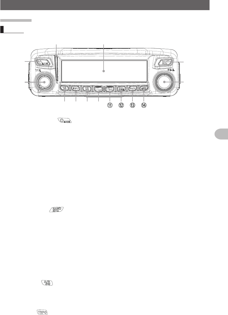
Controller
Front
➀➄
➅
➆ ➇ ➈ ➉
➁
➃
➂
➀ Power/Lock Switch ( )
Pressing for over 2 seconds switches the power between ON and OFF.
Briefly pressing engages or releases the key lock while the radio is turned on.
➁ VOL knob
Turning clockwise increases the volume whereas turning counterclockwise
decreases the volume.
➂ Indicator
• The top half lights green when in BUSY state.
• The top half lights red during transmission.
• The bottom half lights blue while receiving or transmitting digital voice signals.
• The bottom half lights white while receiving or transmitting digital data.
➃ Dot matrix LCD display
➄ BAND MHz key ( )
Switches the bands of the operating band.
Pressing and holding for over 1 second allows you to set the frequency in 5 MHz
units.
➅ DIAL knob
• Allows you to set the operating band frequency.
Turning clockwise increases the frequency whereas turning counterclockwise
decreases the frequency.
• Allows you to select the desired item for setup, memory registration, group
monitoring operation, etc.
➆ A/B DW key ( )
Briefly pressing each time switches the operating band between Band A and Band B.
Pressing for over 1 second each time switches the dual watch function between ON
and OFF.
➇ TXPO key ( )
Briefly pressing each time switches the transmission power (HI/MID/LOW).
Application for FCC / IC
FCC ID: K6620485X40
IC: 511B-20485X40
10
Before Using
Name and Function of Each Component
➈ V/M MW key ( )
Briefly pressing each time switches between VFO mode and memory mode.
Pressing and holding for over 1 second displays the memory registration screen.
➉ D/X key ( )
Briefly pressing each time switches the communication mode of the operating band.
Pressing and holding for over 1 second activates WIRES-X.
GM key ( )
Activates the GM (group monitor) function.
SQL VOICE key ( )
Pressing this button briefly and rotating the DIAL sets the squelch level.
Pressing and holding for over 1 second activates VOICE mode.
BACK key ( )
Briefly pressing enables the selected item or value. Then, the screen returns to the
previous screen.
DISP SETUP key ( )
Briefly pressing switches the display information (Partner station location
information/your location information/GPS INFO).
Tip For details on the display information, see page xx.
Pressing and holding for over 1 second displays the set-up menu.
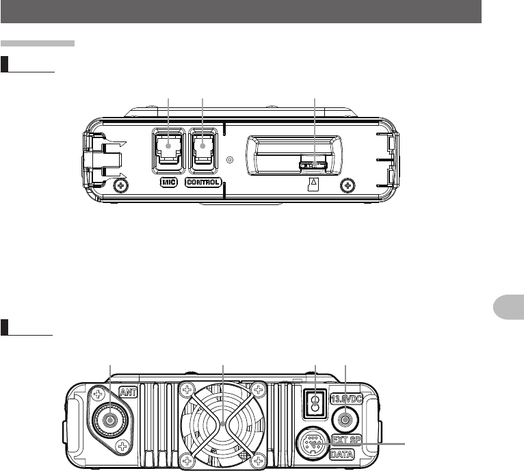
Back
➀
➁
➀ CONTROL jack
Plug in the control cable into this jack to connect with the main body.
➁ Screw hole to attach the mounting bracket
Application for FCC / IC
FCC ID: K6620485X40
IC: 511B-20485X40
11
Before Using
Name and Function of Each Component
Main body
Front
➀ ➁ ➂
➀ CONTROL jack
Plug in the control cable into this jack to connect with the controller.
➁ MIC jack
Plug in the provided microphone cable.
➂ micro-SD card slot
Back
➀➄➁
➃
➂
➀ ANT terminal
Connect the co-axial cable for the antenna.
➁ 13.8 VDC
Connect the provided DC power supply cable (with fuse attached).
➂ EXT SP jack
Connect the optional external speaker.
➃ DATA jack
Connect a cable for remote operation or the cable for connecting with the personal
computer interface unit and the external terminal unit.
➄ Cooling fan
Application for FCC / IC
FCC ID: K6620485X40
IC: 511B-20485X40
12
Before Using
Name and Function of Each Component
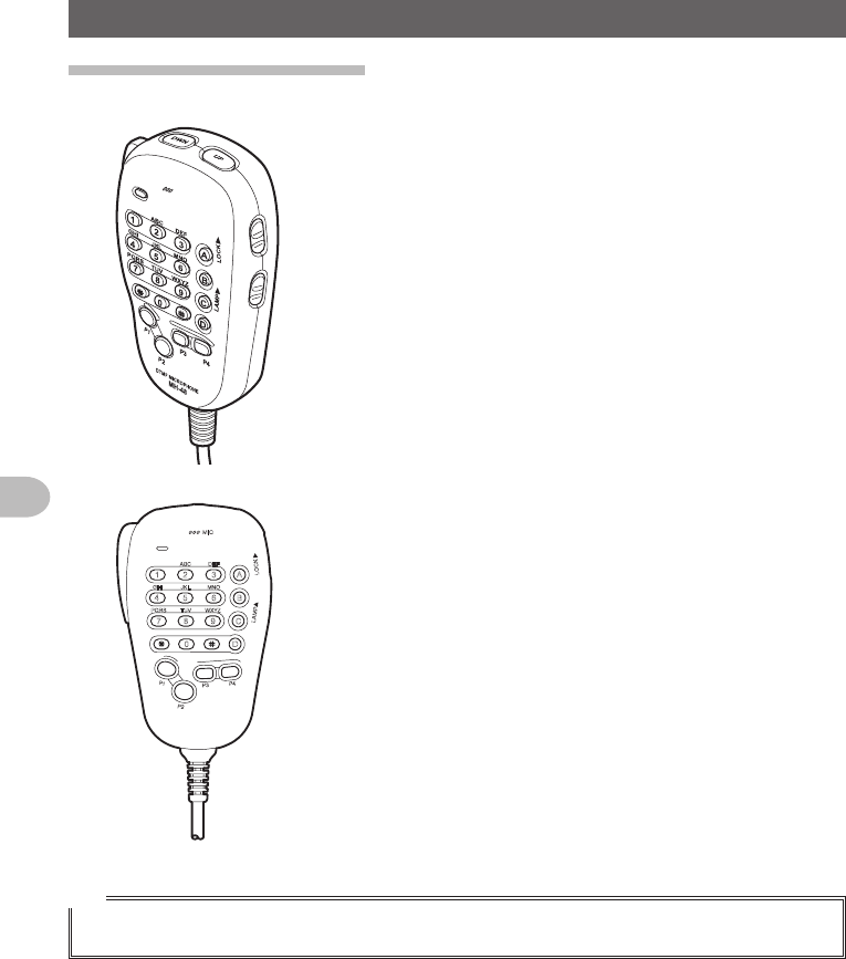
Microphone (MH-48A6JA)
LOCK
P3
P2
P1
7
1
4
8
2
0
5
9
B
A
C
D
3
6
P4
LAMP
DTMF MICROPHONE
MH-48
ABC
JKL
TUV
GHI
PQRS
DEF
MNO
WXYZ
MIC
[UP] Frequency is increased by 1 step.
[DWN] Frequency is decreased by 1 step.
[LOCK] Locks / unlocks the [UP] and [DWN] keys and
[P1] to [P4] keys.
[LAMP] Turns the lamp on the body of the microphone
on/off.
[MIC] Speak into here during transmission.
[1] to [0] Enters the numbers and letters.
[✽] Changes the VFO/Memory operating mode of
the operating band.
[#] Activates the GM (Group Monitor) functions.
[A] Switches the operating band to Band A.
[B] Switches the operating band to Band B.
[C] Adjusts the squelch level.
[D] Switches the display.
[P1] Turns off the squelch
(T.CALL: European version).
[P2] Recalls the receiver home channel.
[P3] Changes the communication mode.
[P4] Changes the transmit power.
[PTT] Press this key to begin the transmit mode.
Tip
Preferred functions can be assigned to buttons [P1] to [P4]. Select using the [CONFIG]→[10MIC
PROGRAM KEY] in the set-up menu.
Application for FCC / IC
FCC ID: K6620485X40
IC: 511B-20485X40
13
Before Using
Name and Function of Each Component
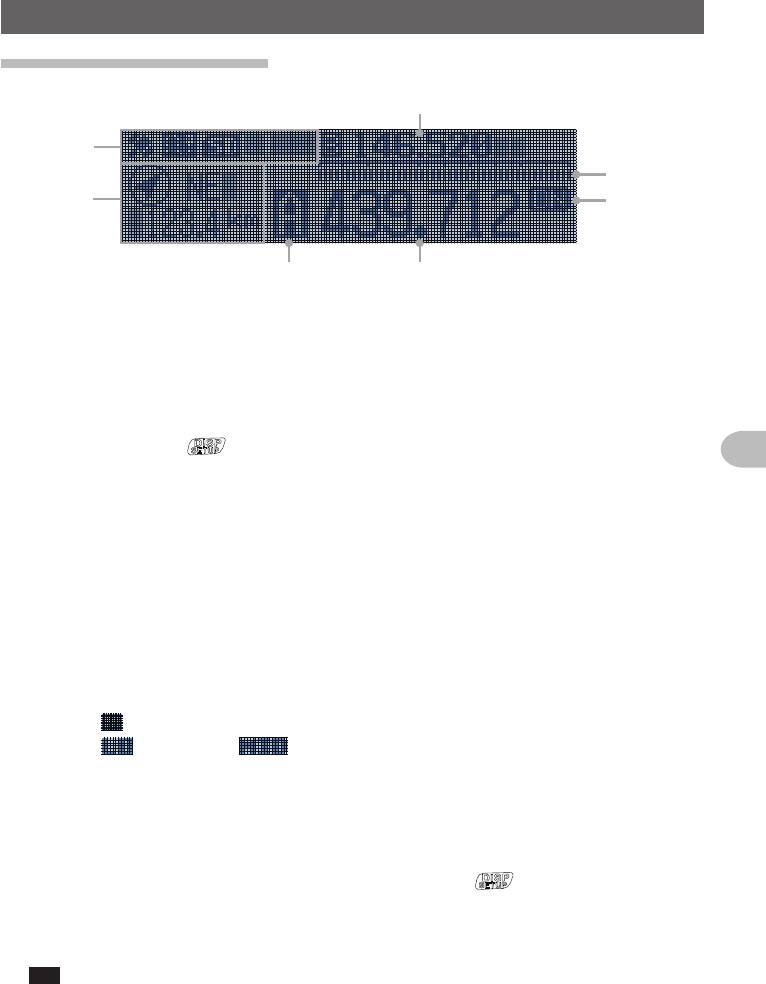
Explanation of the screen
➁
➂
➆➅
➄
➃
➀
➀ Icon display
Displays the Bluetooth, APRS, microSD card and GPS icons when each function is
in use.
➁ Station location information display
Displays the partner station location information and your location information.
Briefly pressing the key each time switches the information to display.
➂ Sub-band frequency display
Displays the sub-band name (A or B) and sub-band frequency.
➃ SQL level display
➄ Communication mode display
Displays the mode name such as analog and digital using abbreviations.
While in Auto mode, a bar appears and flashes above the abbreviation display. In
Auto mode, the communication mode is automatically set according to the receiving
signal.
➅ Operating band name/memory channel/transmission power
Displays the operating band name (A or B) in VFO mode.
Displays and the memory channel number in memory mode.
Displays for “LO” and for “MID”.
➆ Frequency display
Displays the operating band frequency.
●GPS INFO screen
When the partner information is displayed, briefly press the key twice to display the
GPS INFO screen.
The GPS satellite reception status is displayed. ○ appears when the receiving signal is
weak whereas ● appears when the receiving signal is strong.
Tip From [1 DISPLAY] → [4 GPS INFO], you can select “LOCATION” (location display) or
“FREQUENCY” (frequency display).
Application for FCC / IC
FCC ID: K6620485X40
IC: 511B-20485X40

14
Before Using
Installing the Radio
Precautions during installation
Note the following when installing this radio.
Do not install the radio in a place where there is extreme vibration, where there is a
lot of dust, excessive humidity or high temperature, or where it is exposed to direct
sunlight.
Install the radio in a well ventilated position, so heat release is not obstructed
because the heat sink gets hot when transmitting for a long periods of time.
Do not place any objects on top of the main body.
Do not lift up or hold the controller by holding the knob or control cable.
A regulated, negative ground 13.8 V DC power supply is required for this radio.
Check that the car battery is a negative ground 12 V system when using this radio in
a mobile unit. Never connect this radio to the 24 V battery of a large vehicle.
Never connect this radio to a 120 V AC power source.
Note that there is a risk that hum and noise may be introduced, depending on the
installation condition and the external power source used.
Install the device as far away as possible from the TV and radio to avoid TV and radio
interference (TVI, BCI).
In particular, do not install this radio near indoor antenna elements.
About the antenna
A good antenna installation is extremely important for transmission and reception
purposes. Note the following, as the type and characteristics of the antenna largely
determines whether the performance of the radio can be fully realized.
• Use an antenna that suits the installation conditions and application objective.
• Use an antenna that suits the operating frequency band.
• Use an antenna and a co-axial cable with a characteristic impedance of 50Ω.
• Adjust the VSWR (standing wave ratio) until it is 1.5 or less for an antenna with an
adjusted impedance of 50Ω.
• Keep the co-axial cable routing length as short as possible.
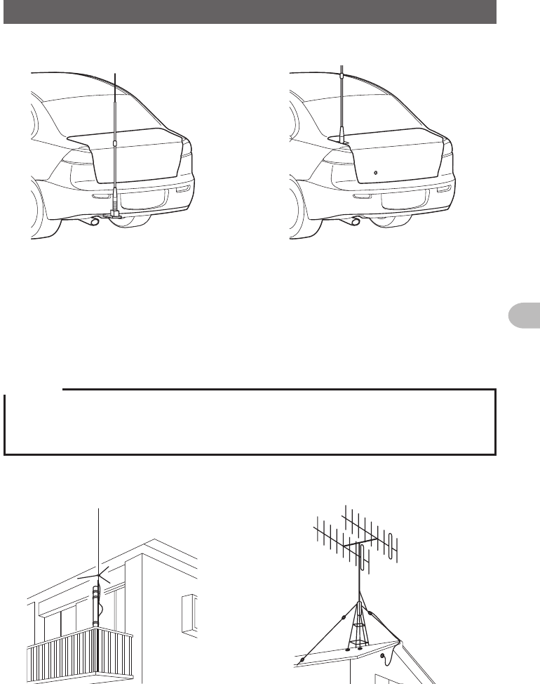
Install the antenna
●Antenna installation in a mobile unit
Mount the antenna base at the rear of the car (rear bumper, trunk, rear gate, etc.) and
then attach the antenna to the base.
Cautions
zEnsure that the antenna base is securely grounded to the car body.
zAvoid routing the co-axial cable enclosed with a commercial car antenna cable.
zDo not allow rain water or moisture to penetrate the cable or connectors when laying the co-axial
cable inside the car.
Installation and Connection
Application for FCC / IC
FCC ID: K6620485X40
IC: 511B-20485X40
15
Before Using
Installing the Radio
Bumper type Trunk type
●Antenna installation in a fixed station
There are omni-directional, and directed array antennas for use in an outdoor setting.
• Omni-directional antennas such as the GP (Ground Plane) antenna are suitable for
communications between a local station and mobile stations in all direction.
• Directional antennas such as the Yagi antenna are suitable for communications
between a base station and a remote station in a specific direction.
Cautions
zCreate a loop (slack) in the co-axial cable directly underneath the antenna and fasten it so that the
weight of the cable does not pull on the antenna or connector itself.
zInstall the antenna taking into consideration the securing supports and how the guying wires are
positioned, so that the antenna does not fall over or get blown away in strong winds.
GP antenna
<Veranda Mounted Example>
Yagi antenna
<Roof Mounted Example>
Installation and Connection
Application for FCC / IC
FCC ID: K6620485X40
IC: 511B-20485X40
16
Before Using
Installing the Radio
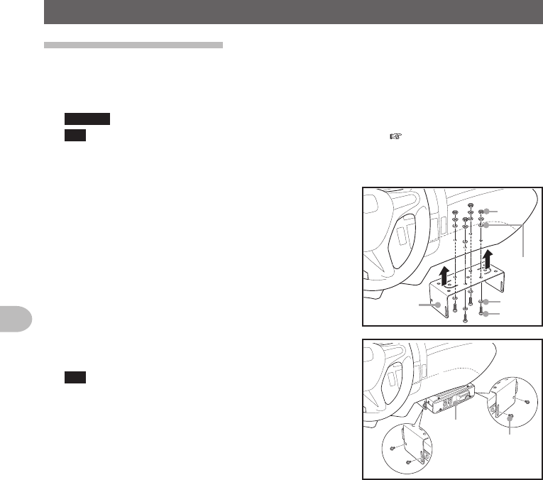
Installing the main body
Install the main body using the provided MMB-36 bracket.
1 Select the installation location
Caution Select a location where the antenna coax and power cable can be securely attached.
Tip Also refer to “Installation location when used in a mobile unit” ( P.xx).
2 Drill four 6 mm diameter holes in the location where the bracket is to be mounted,
matching the positions of the bolting holes of the bracket
3 Attach the bracket using the provided bolts, nuts
and washers Nut
Washer
Washer
Bolt
Bracket
4 Fasten the main body to the bracket, using the
provided flange bolts, as shown in the drawing
Tip The mounting angle can be changed depending on
the securing position of the flange bolts.
Flange bolt
Main body
Application for FCC / IC
FCC ID: K6620485X40
IC: 511B-20485X40