Yaesu Musen 20485X40 Amateur Radio with scanning receiver User Manual Operating Manual
Yaesu Musen Co., Ltd. Amateur Radio with scanning receiver Operating Manual
Contents
- 1. User Manual Part 1
- 2. User Manual Part 2
User Manual Part 2
17
Before Using
Connecting the Radio
Connecting the controller to the main body
Caution
Make sure the power supply is switched OFF before connecting the cable between the controller and
the main body.
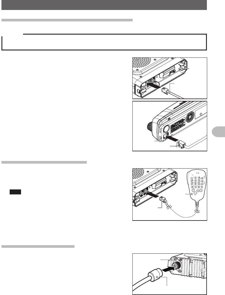
1 Plug the connector of the controller cable into the
[CONTROL] jack at the front of the main body
until a click sound is heard
Main
body
Controller
cable
2 Plug the other connector of the controller cable
into the [CONTROL] jack at the back of the
controller until a click sound is heard
Controller cable
Controller
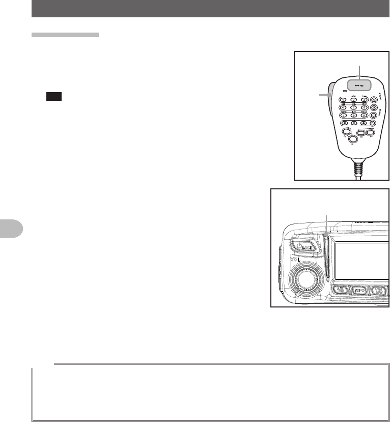
Connecting the microphone
1 Plug the microphone connector into the [MIC]
jack at the front of the main body until a click
sound is heard
Tips • To remove the microphone, pull the connector out
while pressing the latch.
• Using the optional microphone extension kit “MEK-
2”, a microphone with a 8-pin connector can be
used. A microphone extension cable (about 3 m
long) is also included in MEK-2. Use it to install the
microphone in locations which cannot be reached
by the attached microphone cable.
LOCK
P3
P2
P1
7
1
4
8
2
0
5
9
B
A
C
D
3
6
P4
LAMP
DTMF MICROPHONE
MH-48
ABC
JKL
TUV
GHI
PQRS
DEF
MNO
WXYZ
MIC
Connector
Microphone
Connecting the antenna
1 Attach the antenna co-axial cable to the [ANT]
terminal at the back of the main body and tighten
the connector
同軸ケーブル端子
本体(後面)
Main body
(rear side)
Co-axial cable connector
Application for FCC / IC
FCC ID: K6620485X40
IC: 511B-20485X40
18
Before Using
Connecting the Radio
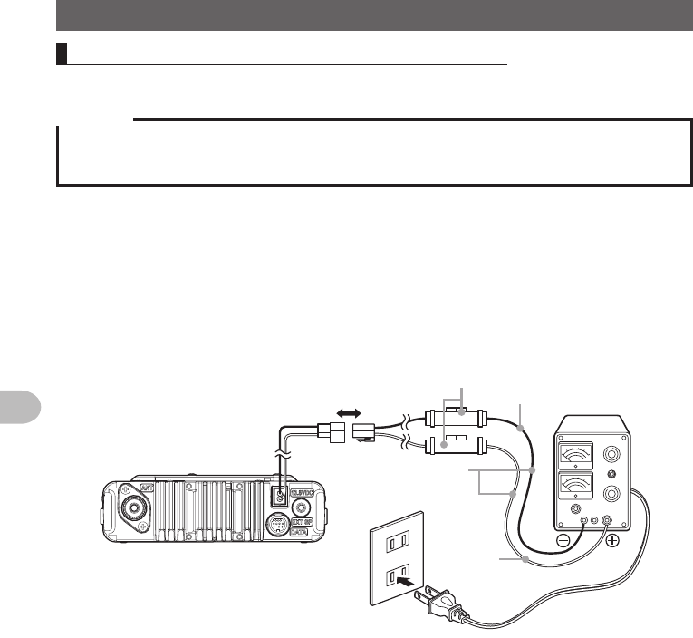
Connecting the externalpowersupplyequipment
When using this radio as a fixed station, use an external 12 V DC power source.
Cautions
zUse an external power source capable of supplying DC 13.8 V, a current capacity of 20 A or more
(FTM-100DR).
zMake sure to switch OFF the power of the external power source before connecting.
1 Connect the red wire (+) of the provided DC power supply cable to the positive
(+) terminal of the external power source, and the black wire (-) to the negative (-)
terminal of the external power source
2 Connect the DC power supply cable to the connector of the power cord of the main
body
Press the plug into the connector until a click sound is heard.
本体後面
電源コード
(DC(直流)
13.8V)
黒色 直流安定化
電源装置
AC100V
コンセント
DC電源ケーブル
(付属品)
ヒューズ
ホルダー
赤色
Power cord (DC
(direct current)
13.8 V)
Rear side of main body
Black
Red
AC line
outlet
DC power supply
cable (accessory)
Fuse holder
Direct current
13.8 V DC power
supply
Application for FCC / IC
FCC ID: K6620485X40
IC: 511B-20485X40

19
Before Using
Setting Up the micro-SD Card
The following operations can be carried out by using a micro-SD card in this radio.
• Backing up the information and settings of the radio
• Saving the information in the memory channels
• Saving the settings in the set-up mode
• Saving the GPS log data
• Saving data that has been downloaded using the GM function and WIRES-X function
• Exchanging the saved data among multiple radios
Micro-SD cards that can be used
2 GB, 4 GB, 8 GB, 16 GB and 32 GB micro-SDHC cards can be used in this radio.
Cautions
zThe micro-SD or micro-SDHC cards are not provided with the product.
zNot all micro-SD and micro-SDHC cards sold commercially are guaranteed to work with this
product.
Things to note when using micro-SD cards
• Do not bend the micro-SD card or place heavy objects on top of it.
• Do not touch the terminal face of the micro-SD card with your bare hands.
• Micro-SD cards that are initialized in other devices may not record normally when
used in this device. Re-initialize the micro-SD card in this radio when using a card
that has been initialized in another device. (Refer to Page xx on how to initialize the
memory card)
• Do not pull the micro-SD card out, or switch the power to the radio OFF when reading
or writing data to the card.
• Do not insert anything other than a micro-SD card into the micro-SD card slot of the
radio.
• Do not pull out or insert the micro-SD card with unreasonable force.
• When a single micro-SD card is used for a long period of time, writing and deletion of
data may become disabled. Use a new micro-SD card when data can no longer be
written or erased.
• Note that Yaesu shall not be liable for any damages suffered as a result of data loss
or corruption in use of the micro-SD card.
Application for FCC / IC
FCC ID: K6620485X40
IC: 511B-20485X40
20
Before Using
Setting Up the micro-SD Card
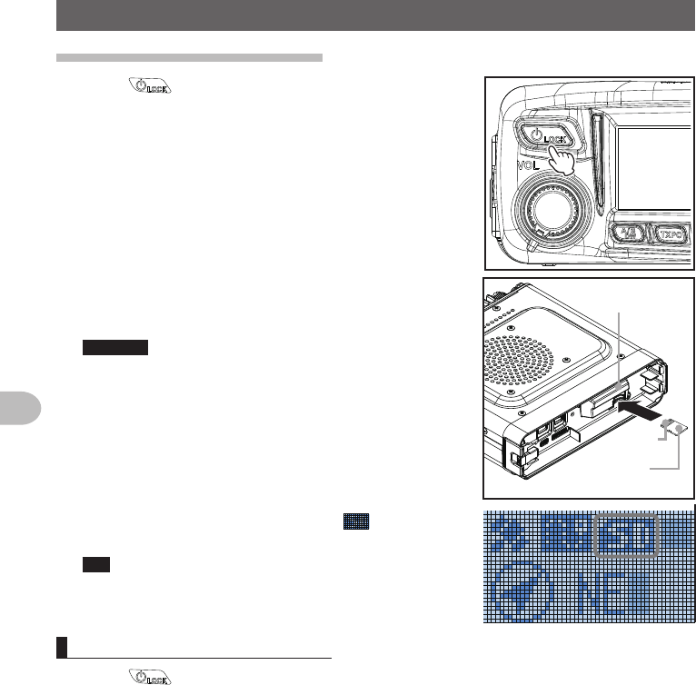
Installing the micro-SD card
1 Press for 2 seconds or longer to switch off the
power to the main body
2 Insert the micro-SD card into the micro-SD card slot,
with the terminal face on top, until a click sound is
heard
Cautions z Insert the micro-SD card in the correct direction.
z Do not touch the terminal of the micro-SD card
with your hands.
Terminal
face
microSD
card slot
microSD card
After the power is switched on, the “ ” icon will be
displayed at the top right of the display.
Tip It may take a while for the icon to appear depending on
the card capacity.
Removing the micro-SD card
1 Press for 2 seconds or longer to switch off the power to the main body
2 Push in on the microSD card
A click sound will be heard and the micro-SD card will be pushed outward.
3 Pull the micro-SD card from the micro-SD card slot
Application for FCC / IC
FCC ID: K6620485X40
IC: 511B-20485X40
21
Before Using
Setting Up the micro-SD Card
Initializing the micro-SD card
When using a new micro-SD card, initialize the micro-SD card according to the following
procedure.
Caution
Upon initialization, all the data recorded in the micro-SD card will be erased. Check the contents of
the micro-SD card before initialization.
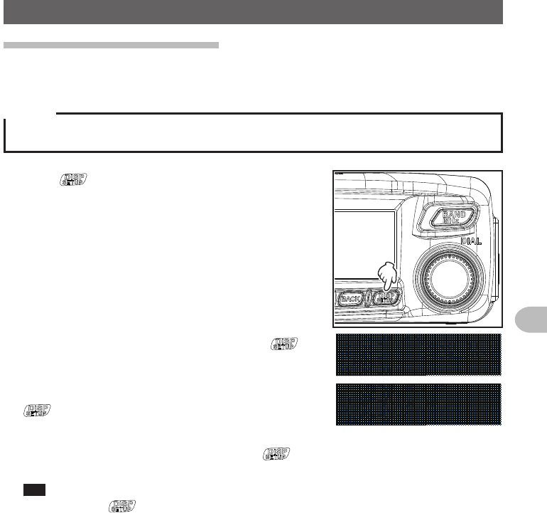
1 Press for one second or longer
The set-up menu will be displayed.
2 Turn the DIAL to select [11 SD], then press
The menu list will be displayed.
3 Turn the DIAL to select [4 FORMAT], then press
The format confirmation screen will be displayed.
4 Turn the DIAL to select [OK?], then press
The micro-SD card will be initialized.
Tip To cancel initialization, turn the DIAL to select [Cancel],
then press .
“Completed” will be displayed when initialization
is completed and the screen will then return to the
menu list.
Application for FCC / IC
FCC ID: K6620485X40
IC: 511B-20485X40
22
Before Using
Receiving
Turning the power on
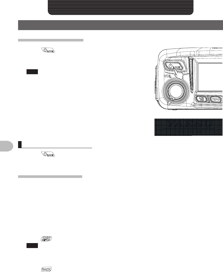
1 Press for 2 seconds or longer
The power will be switched on, and the display will
appear on the screen.
Tips • When switching the power on for the first time after
purchasing, or after resetting, a screen requesting
the call sign of your own station be entered, will be
displayed.
• From the second time onwards, the call sign of your
own station entered the first time will be displayed.
Switching the power off
1 Press for 2 seconds or longer
The screen display will disappear, and the power will be switched off.
Inputing the call sign
When switching the power on for the first time after
purchasing, or after resetting the device, a screen
requesting the call sign of your own station be entered
will be displayed.
The call sign is used to identify the transmitting station when communicating in the
digital mode.
1 Turn the DIAL to select the desired characters, then
press
Tips • Up to 10 characters (letters, numbers, and a hyphen )
can be entered.
• Refer to Page xx on how to operate the character input
screen.
2 Press
The screen will change.
Thereafter, the entered call sign is displayed at the
bottom of the power on screen, and the display will
switch to the frequency display screen (dual band
screen).
Basic Operations
Application for FCC / IC
FCC ID: K6620485X40
IC: 511B-20485X40
23
Before Using
Receiving
Basic Operations
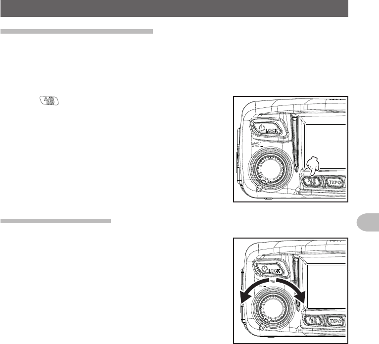
Switching the operating band
The two bands are displayed at the top and bottom of the dual band screen. You
can change the frequency and type of radio wave only for “operating band” which is
displayed at the lower part of the screen. The other band is called “sub-band” which is
displayed at the top part of the screen.
1 Press
Pressing each time switches the operating band
between Band A and Band B.
Adjustingthevolume
1 Turn VOL
Turning clockwise increases the volume whereas
turning counterclockwise decreases the volume.
Application for FCC / IC
FCC ID: K6620485X40
IC: 511B-20485X40
24
Before Using
Receiving
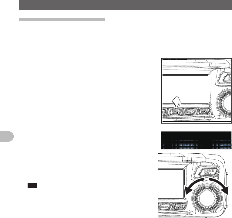
Adjustingthesquelchlevel
Annoying noises can be muted when a signal cannot be detected. Band A and Band B
squelch levels can be individually adjusted. Noise can be canceled more easily when
the squelch level is increased but it may become more difficult to pick up weak signals.
Adjust the squelch level as required.
1 Press [SQL]
The sub-band will be displayed, and the current
squelch level will be displayed on the SQL meter.
2 Turn the DIAL to adjust the squelch level
The squelch level displayed on the sub-band display
and the level displayed on the SQL meter will be
changed.
Tip If you do not perform any operation for 3 seconds after
changing the meter display or turning the DIAL, the
screen will return to the normal screen.
Application for FCC / IC
FCC ID: K6620485X40
IC: 511B-20485X40
25
Before Using
Receiving
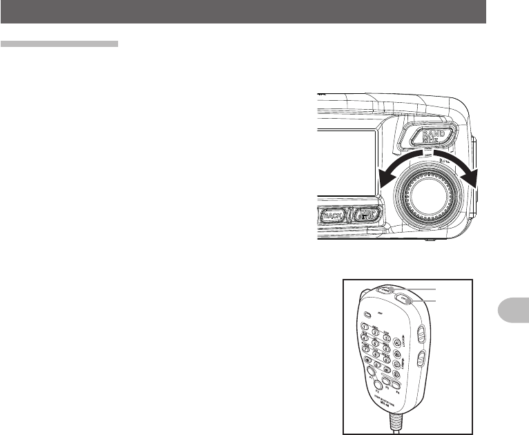
Tuning the radio
●Using the knobs
1 Turn the DIAL
The frequency will increase when the knob is turned
in a clockwise direction and decrease when turned in
a counter-clockwise direction.
●Using the microphone keys
1 Press [UP] or [DWN]
The frequency increases when [UP] is pressed, and
decreases when [DWN] is pressed.
UP
DWN
Application for FCC / IC
FCC ID: K6620485X40
IC: 511B-20485X40
26
Before Using
Communicating
Transmitting
1 Press and hold the microphone [PTT]
The top half of the indicator will light red.
2 Talk directly into the microphone [MIC]
Tip Keep the microphone at a distance of about 1 inch away
from the mouth when talking.
LOCK
P3
P2
P1
7
1
4
8
2
0
5
9
B
A
C
D
3
6
P4
LAMP
DTMF MICROPHONE
MH-48
ABC
JKL
TUV
GHI
PQRS
DEF
MIC
MNO
WXYZ
PTT
MIC
The top half of the
indicator will light red.
3 Release [PTT]
The red bar and PO meter level will disappear and the radio will return to the
receiving state.
Tips
• Refrain from transmitting continuously for a long period of time as much as possible. The
temperature of the main body will rise and this may result in burns and equipment failure due to
overheating.
• “ERROR TX FREQ” will be displayed when attempting to transmit on a frequency that is not in the
amateur band.
Application for FCC / IC
FCC ID: K6620485X40
IC: 511B-20485X40
27
Before Using
Communicating
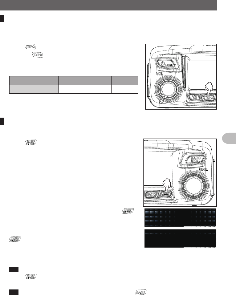
Adjustingthetransmitpower
When communicating with a nearby station, the transmit power can be reduced to save
on energy consumption.
1 Press
Pressing each time switches the transmission
power in the following order.
“HI” → “LO” → “MD”
Model HI MD LO
FTM-100DR 0W 20W 5W
Adjustingthesensitivityofthemicrophone
The sensitivity (gain) of the microphone can be adjusted.
1 Press for one second or longer
The set-up menu will be displayed.
2 Turn the DIAL to select [2 TX/RX], then press
The menu list will be displayed.
3 Turn the DIAL to select [2 MIC GAIN], then press
The microphone gain setting value will be displayed.
4 Turn the DIAL to select the desired microphone gain
“1 MIN” → “2 LOW” → “3 NORMAL” → “4 HIGH”
Tip Factory default value: NORMAL
5 Press for one second or longer
The sensitivity is set and the display returns to the previous screen.
Tip You can also return to the previous screen by pressing 3 times.
Application for FCC / IC
FCC ID: K6620485X40
IC: 511B-20485X40

28
Before Using
Communicating
Communicating in the FM mode
1 Choose the operating band
2 Select “MANUAL (FM)” as the modulation mode
3 Turn the DIAL to tune in to the frequency
4 Press and hold the microphone [PTT] to talk
Tip
You can also use the half deviation. From [2 TX/RX] → [8 HALF DEVIATION] in the set-up menu,
select “ON”.
Application for FCC / IC
FCC ID: K6620485X40
IC: 511B-20485X40

29
Before Using
Specification
●General
Frequencyrange : TX 144 - 146 MHz or 144 - 148 MHz
430 - 440 MHz or 430 - 450 MHz
:RX 108 - 137 MHz (Air Band)
137 - 174 MHz (144 MHz HAM)
174 - 400 MHz (GEN1)
400 - 480 MHz (430 MHz HAM)
480 - 999.99 MHz (GEN2)
Channelsteps : 5/6.25/8.33/10/12.5/15/20/25/50/100 kHz
(8.33 kHz : only for Air band)
EmissionType : F1D, F2D, F3E, F7W
Frequencystability : ±2.5 ppm −4°F to +140°F (−20°C to +60°C)
Antennaimpedance : 50 Ω
SupplyVoltage : Norminal 13.8 V DC, negative ground
Currentconsumption : 0.5 A (receive)
11 A (50 W TX, 144 MHz)
12 A (50 W TX, 430 MHz)
Operatingtemperature : −4°F to +140°F (−20°C to +60°C)
Casesize : Radio unit: 5.5" (W) × 1.6" (H) × 4.9" (D) (140 × 40 × 125 mm) w/o fan
Controller: 5.5" (W) × 2.8" (H) × 0.8" (D) (140 × 72 × 20 mm)
Weight(approx.) : 2.64 lbs (1.2 kg) with radio unit, controller, control cable
●Transmitter
RFpoweroutput : 50/20/5 W
Modulationtype : F1D, F2D, F3E : Variable Reactance Modulation
F7W : 4FSK (C4FM)
Spuriousemission : At least 60 dB below
Microphoneimpedance : About 2 kΩ
DATA terminal input impedance
: About 10 kΩ
Application for FCC / IC
FCC ID: K6620485X40
IC: 511B-20485X40

30
Before Using
Specification
●Receiver
Circuittype : Double conversion super-heterodyne
Intermediatefrequencies : A band:
1st : 47.25 MHz, 2nd :450 kHz
B band:
1st : 44.85 MHz, 2nd : 450 kHz
ReceiverSensitivity : 108 - 137 MHz (AM) 0.8μV typ for 10 dB SN
137 - 140 MHz (FM) 0.2μV for 12 dB SINAD
140 - 150MHz (FM) 0.2μV for 12 dB SINAD
150 - 174 MHz (FM) 0.25μV for 12 dB SINAD
174 - 222 MHz (FM) 0.3μV typ for 12 dB SINAD
222 - 300 MHz (FM) 0.25μV typ for 12 dB
SINAD
300 - 336 MHz (AM) 0.8μV typ for 10 dB SINAD
336 - 420 MHz (FM) 0.25μV for 12 dB SINAD
420 - 470 MHz (FM) 0.2μV typ for 12 dB SINAD
470 - 520 MHz (FM) 0.2μV for 12 dB SINAD
800 - 900 MHz (FM) 0.4μV typ for 12 dB SINAD
900 - 999.99 MHz (FM) 0.8μV typ for 12 dB SINAD
Cellular blocked (USA only)
Digital mode
140 - 150 MHz (Digital) 0.19μV typ for BER 1%
420 - 470 MHz (Digital) 0.19μV typ for BER 1%
Squelchsensitivity : 0.16μV (144/430 MHz)
Selectivity : AM, FM 12 kHz/35 kHz (−6 dB/−60 dB)
AFoutput : 3 W (8 Ω, THD10%, 13.8 V) internal speaker
8 W (4 Ω, THD10%, 13.8 V) Optional MLS-200-M10
AFoutputimpedance : 4 - 16 Ω
Strength of secondary radio waves
:4 nW and below
Cautions
zRated values are at normal temperature and pressure.
zRatings and specifications are subject to change without notice.
Application for FCC / IC
FCC ID: K6620485X40
IC: 511B-20485X40

31
Before Using
Specification
1. Changes or modifications to this device not expressly approved by YAESU MUSEN could void the
user’s authorization to operate this device.
2. This device complies with part 15 of the FCC Rules. Operation is subject to the following two
conditions: (1) This device may not cause harmful interference, and (2) this device must accept any
interference including received, interference that may cause undesired operation.
3. The scanning receiver in this equipment is incapable of tuning, or readily being altered, by the User
to operate within the frequency bands allocated to the Domestic public Cellular Telecommunications
Service in Part 22.
DECLARATION BY MANUFACTURER
The Scanner receiver is not a digital scanner and is incapable of being converted or modified to a
digital scanner receiver by any user.
WARNING: MODIFICATION OF THIS DEVICE TO RECEIVE CELLULAR RADIOTELEPHONE
SERVICE SIGNALS IS PROHIBITED UNDER FCC RULES AND FEDERAL LAW.
This device complies with Industry Canada license-exempt RSS standard(s). Operation is subject
to the following two conditions: (1) this device may not cause interference, and (2) this device must
accept any interference, including interference that may cause undesired operation of the device.
Le présent appareil est conforme aux CNR d’Industrie Canada applicables aux appareils radio
exempts de licence. L’exploitation est autorisée aux deux conditions suivantes : (1) l’appareil ne doit
pas produire de brouillage, et (2) l'utilisateur de l’appareil doit accepter tout brouillage radioélectrique
subi, même si le brouillage est susceptible d’en compromettre le fonctionnement.
Application for FCC / IC
FCC ID: K6620485X40
IC: 511B-20485X40

YAESU MUSEN CO., LTD.
Tennozu Parkside Building
2-5-8 Higashi-Shinagawa, Shinagawa-ku, Tokyo
140-0002 Japan
YAESU USA
6125 Phyllis Drive, Cypress, CA 90630, U.S.A.
YAESU UK
Unit 12, Sun Valley Business Park, Winnall Close
Winchester, Hampshire, SO23 0LB, U.K.
Copyright 2015
YAESU MUSEN CO., LTD.
All rights reserved.
No portion of this manual
may be reproduced
without the permission of
YAESU MUSEN CO., LTD.
Printed in Japan
1409P-AO
Application for FCC / IC
FCC ID: K6620485X40
IC: 511B-20485X40