Yaesu Musen 20523X51 ANALOGUE SCANNING RECEIVER User Manual OM
Yaesu Musen Co., Ltd. ANALOGUE SCANNING RECEIVER OM
User Manual
16
Basic Operation
FTM-3100R Operating Manual
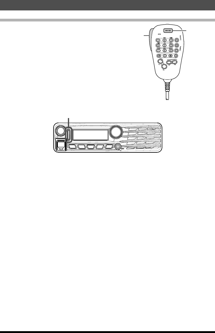
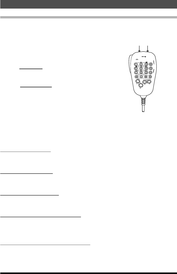
Transmission
1. Press and hold PTT on the microphone.
Both the upper and lower portions of the PTT
mode/status indicator light red.
LOCK
P3
P2
P1
7
1
4
8
2
0
5
9
B
A
C
D
3
6
P4
LAMP
DTMF MICROPHONE
MH-48
ABC
JKL
TUV
GHI
PQRS
DEF
MNO
WXYZ
MIC
MIC
PTT
VOL
DIAL
DW MW
SETUP
REV V/M
SQL TXPO MHz
Both the upper and lower portions light red
2. Speak into MIC on the microphone.
Note: Keep the microphone about 5 cm away from your mouth.
The sensitivity (gain) of the microphone can be adjusted. For details, refer to the
Advanced Manual (download from the Yaesu website).
3. Release PTT.
The transmit mode/status indicator turns off and the transceiver returns to the receive
mode.
Caution: Do not continue transmitting for a prolonged period. The transceiver may
overheat, resulting in malfunction or injury.
Note: “ERROR” appears if you attempt to transmit on an unavailable frequency.
Application for FCC / IC
FCC ID: K6620523X51 / IC: 511B-20523X51
17
Basic Operation
FTM-3100R Operating Manual
Adjusting the transmit power
When communicating with a nearby station, the transmit power level may be lowered to
reduce the battery power consumption.
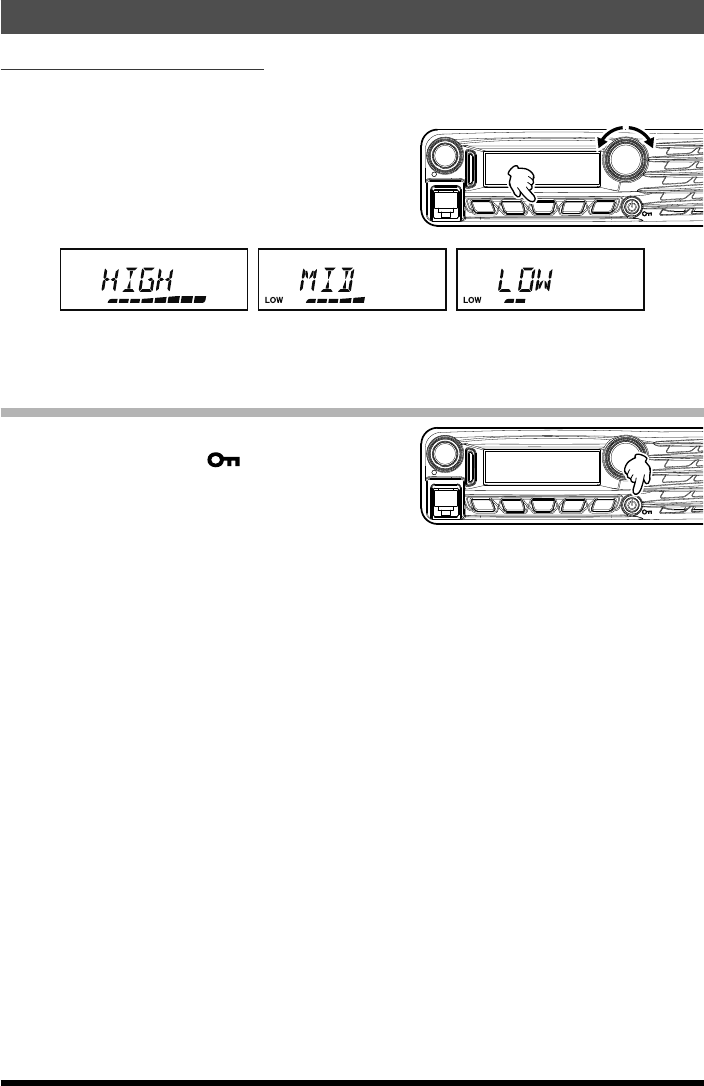
1. Press the [TXPO] key.
2. Rotate the DIAL to select the transmit pow-
er.
Note: The default setting: HIGH
VOL
DIAL
DW MW
SETUP
REV V/MMHz
SQL TXPO
HIGH (65 W) MID (30 W) LOW (5 W)
3. Press the [TXPO] key to save the new setting and exit to normal operation.
Lock Feature
To activate the key-lock feature, press the
[Power(Lock)] key. The “ ” icon will appear
on the LCD.
To cancel key-lock, press the [Power(Lock)]
key again.
VOL
DIAL
DW MW
SETUP
REV V/MMHz
SQL TXPO
To select which keys are locked, use the Setup Menu Item “17 LOCK” see page 30 for
details.
Application for FCC / IC
FCC ID: K6620523X51 / IC: 511B-20523X51
18 FTM-3100R Operating Manual
Advanced Operation
Repeater Operation
The FTM-3100R includes the ARS (Automatic Repeater Shift) function, which permits
communication through repeaters automatically, by simply setting the receiver to the re-
peater frequency.
1. Tune to the repeater frequency.
2. Press the PTT to transmit.
During transmission, radio waves having an 100.0 Hz* tone signal are emitted on the
frequency offset from the receive frequency by 0.6 MHz*.
*: Depends on the transceiver version.
Note: From the Setup Menu, you can change the repeater setting.
RPT ARS 29 à Deactivates the ARS function.
RPT FREQ 30 à Allows changing the repeater shift frequency offset.
RPT SFT 31 à Allows setting the repeater shift direction.
Checking the Repeater Uplink (Input) Frequency
It is often helpful to be able to check the uplink (input) frequency of a repeater, to see if
the calling station is within direct (“Simplex”) range.
To do this, just press the [REV(DW)] key. You’ll
notice that the display has shifted to the repeat-
er uplink frequency. Press the [REV(DW)] key
again to cause operation to revert to normal
monitoring of the repeater downlink (output)
frequency. While listening on the repeater input
frequency using the [REV(DW)] key, the repeat-
er offset icon will blink.
Blinks
Application for FCC / IC
FCC ID: K6620523X51 / IC: 511B-20523X51
19
Advanced Operation
FTM-3100R Operating Manual
Weather Broadcast Reception
The FTM-3100R includes a unique feature which allows reception of weather broadcasts
in the 160 MHz frequency range. Ten standard Weather Broadcast channels are preload-
ed into a special memory bank.
To listen to a Weather Broadcast Channel:
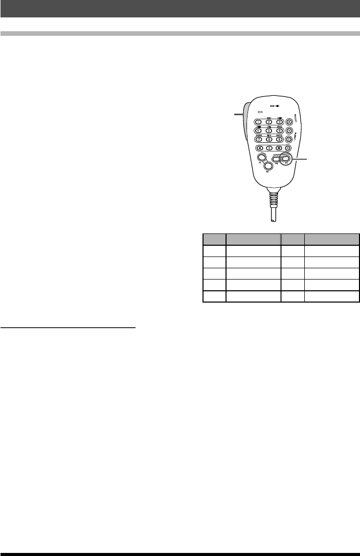
1. Press the Microphone [P4] button to recall
the Weather Broadcast channels.
Note: The [P4] key, one of the programma-
ble keys, is assigned (default setting)
as the “WX Broadcast” one-touch
access key. Please note that if you
change/assign another function to the
[P4] key, one-touch access to the WX
channel will be unavailable.
2. Turn the DIAL knob to select the desired
Weather Broadcast channel.
3. To scan the other channels for activity,
press the Microphone PTT switch.
4. To exit to normal operation, press the [P4]
button again. Operation will return to the
VFO or Memory channel in operation before
you began Weather Broadcast operation.
LOCK
P3
P2
P1
7
1
4
8
2
0
5
9
B
A
C
D
3
6
P4
LAMP
DTMF MICROPHONE
MH-48
ABC
JKL
TUV
GHI
PQRS
DEF
MNO
WXYZ
MIC
P4 key
PTT
CH Frequency CH Frequency
1 162.550 MHz 6 162.500 MHz
2 162.400 MHz 7 162.525 MHz
3 162.475 MHz 8 161.650 MHz
4 162.425 MHz 9 161.775 MHz
5 162.450 MHz 10 163.275 MHz
Severe Weather Alert Feature
In the event of extreme weather disturbances, such as storms and hurricanes, NOAA (the
National Oceanic and Atmospheric Administration) sends a weather alert accompanied
by a 1050 Hz tone and subsequent weather report on one of the NOAA weather chan-
nels. You may enable this feature via Setup Menu Item “43 WX ALERT” see page 31
for details.
Application for FCC / IC
FCC ID: K6620523X51 / IC: 511B-20523X51
20
Advanced Operation
FTM-3100R Operating Manual
CTCSS Operation
This radio is equipped with the CTCSS (Continuous Tone-coded Squelch System) that
allows audio to be heard only when receiving signals containing a tone corresponding to
the tone squelch menu setting. By matching the CTCSS tone with the partner station in
advance, quiet standby monitoring is possible.
1. Press and hold the [MHz(SETUP)] key for over one second.
The Setup menu appears.
2. Rotate the DIAL knob to select “SQL TYPE 35”, then press the [MHz(SETUP)] key.
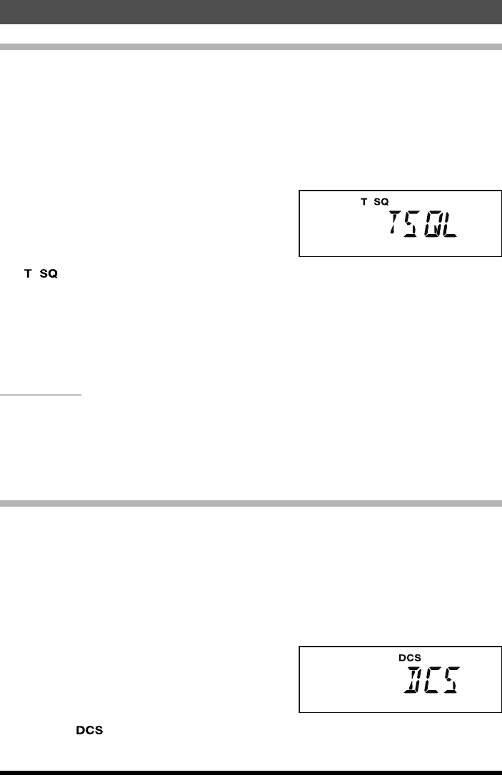
3. Rotate the DIAL knob to select “TSQL”, then
press and hold the [MHz(SETUP)] key for
over one second.
“ ” is displayed on the screen. Now the squelch opens only when receiving tone
signals of the set frequency.
Note: From the Setup Menu, you can change the CTCSS setting.
TONE FRQ 38 à The tone frequency can be selected from 50 frequencies.
BELL 6 à A bell tone (beep) may be set to sound when signals containing
a corresponding CTCSS tone are received.
Tone Search
When the CTCSS tone being transmitted by another station is not known, you can tune
the radio to the incoming signal and activate tone scan to search for and identify the tone
being used.
Note: For details, refer to the Advanced Manual (download from the Yaesu website).
DCS Operation
This radio is equipped with a DCS (Digital Coded Squelch) function that allows audio to
be heard only when signals containing the corresponding DCS code are received. By
matching the DCS code with the partner stations beforehand, a quiet receive standby is
possible.
1. Press and hold the [MHz(SETUP)] key for over one second.
The Setup menu appears.
2. Rotate the DIAL knob to select “SQL TYPE 35”, then press the [MHz(SETUP)] key.
3. Rotate the DIAL knob to select “DCS”, then
press and hold the [MHz(SETUP)] key for
over one second.
Displays “ ” on the screen. The squelch opens only when receiving a signal con-
taining the corresponding DCS code.
Application for FCC / IC
FCC ID: K6620523X51 / IC: 511B-20523X51

21
Advanced Operation
FTM-3100R Operating Manual
Note: From the Setup Menu, you can change the DCS setting.
DCS CODE 9 à The DCS code can be selected from 104 codes.
BELL 6 à A bell tone (beep) may be set to sound when signals containing
a corresponding DCS code are received.
DCS Search
When the DCS code being transmitted by another station is not known, you can tune the
radio to the incoming signal and activate DCS code scan to search for and identify the
DCS code being used.
Note: For details, refer to the Advanced Manual (download from the Yaesu website).
The following features are also available:
EPCS (Enhanced Paging & Code Squelch) Operation
Use the pager code consisting of two CTCSS tones to exchange communications with
specified stations.
Note: For details, refer to the Advanced Manual (download from the Yaesu website).
Split Tone Operation
The FTM-3100R can be operated in a “Split Tone” configuration that enables operation on
repeaters using a mix of both CTCSS and DCS control via the Setup menu.
Note: For details, refer to the Advanced Manual (download from the Yaesu website).
DTMF Operation
DTMF tones (Dual Tone Multi Frequencies) are the tones you hear when dialing from a
telephone keypad. The FTM-3100R transceiver can transmit the DTMF codes by using
the keys on the microphone or recalling registered number strings from memories.
The maximum of 16-digit DTMF codes can be registered in up to 10 memory channels.
It is convenient to register telephone patch numbers, and network linking sequences to
the DTMF memory channels.
Note: For details, refer to the Advanced Manual (download from the Yaesu website).
Application for FCC / IC
FCC ID: K6620523X51 / IC: 511B-20523X51
22 FTM-3100R Operating Manual
Memory Operation
The FTM-3100R provides a wide variety of memory system resources. These include:
r 199 “basic” memory channels, numbered “1” through “199”.
r A “Home” channel, providing storage and quick recall of one prime frequency.
r 10 sets of band-edge memories, also known as “Programmable Memory Scan” chan-
nels, labeled “L0/U0” through “L9/U9”.
Each memory may be appended with an alphanumeric label of up to 8 characters, for
quick channel recognition.
Memory Storage
1. In the VFO mode, select the desired frequency, repeater shift, CTCSS/DCS tone, and
TX power level.
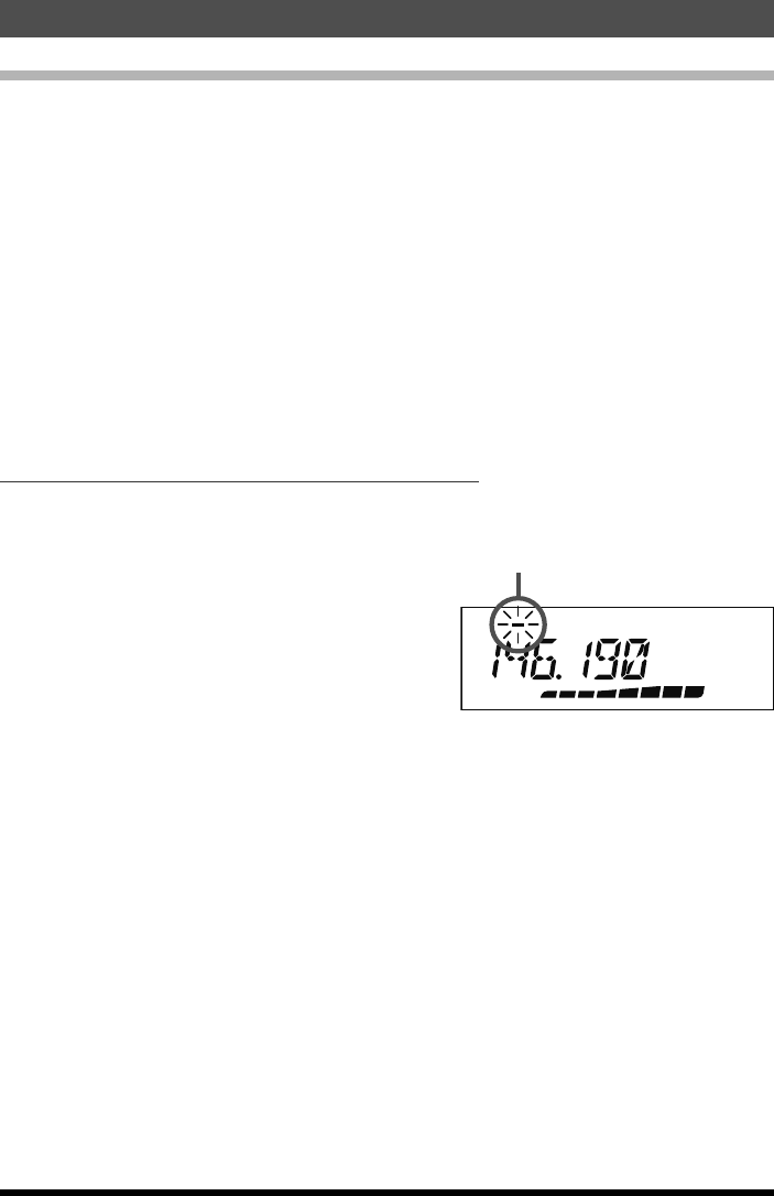
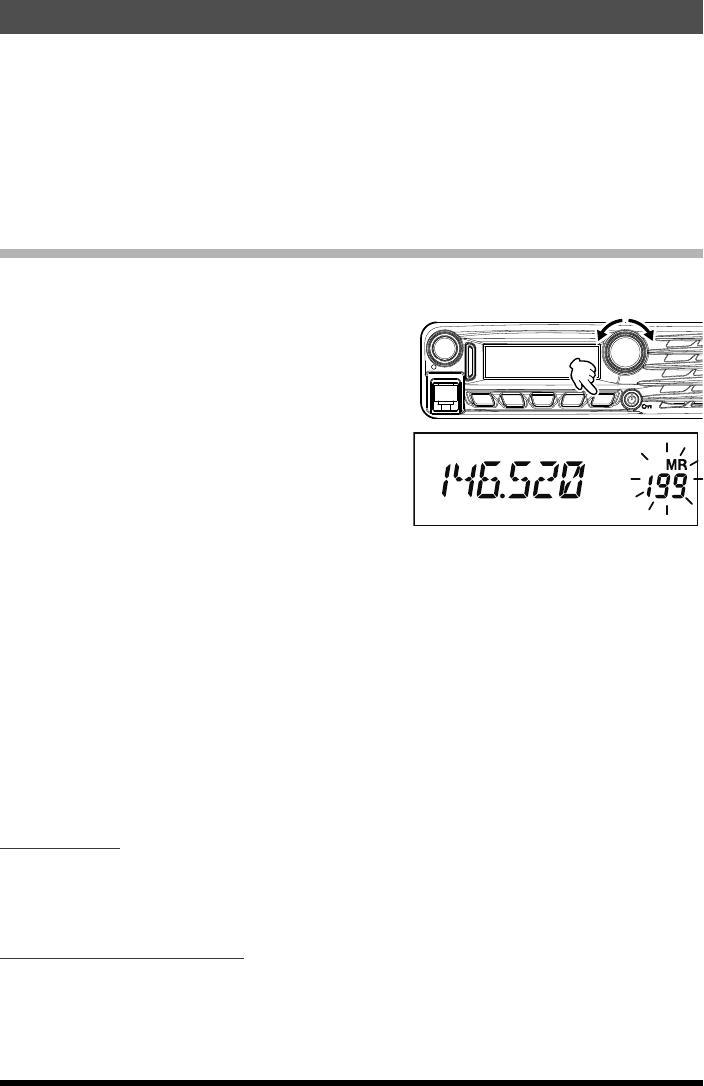
2. Press and hold the [V/M(MW)] key for one
second.
A memory number will appear in the bottom
right corner of the display.
Note: If the channel number is blinking,
there currently is no data stored on
that channel; if the channel number is
not blinking, that channel is currently
“occupied” by other frequency data.
VOL
DIAL
DW MW
SETUP
REV V/MMHz
SQL TXPO
3. Within five seconds of pressing the [V/M(MW)] key, use the DIAL knob to select the
desired memory into which you wish to store the frequency.
Note: While operating in the Memory Storage mode, the keypad of the MH-48A6JA
Microphone may be used to enter the memory channel number directly.
To do this, enter the desired Channel Number on the keypad and then press the
[#] key. Refer to the “For example” of the “Memory Recall from the Microphone
Keypad“ on next page.
4. Press the [V/M(MW)] key again, this time momentarily, to store the displayed data into
the selected memory channel slot.
5. To store additional frequencies, repeat steps 1 through 4, remembering to set the re-
peater shift, CTCSS/DCS tone, and TX power level, as appropriate.
Split Memory
A separate transmit frequency may be registered to a memory channel to which a receive
frequency has already been registered.
Note: For details, refer to the Advanced Manual (download from the Yaesu website).
Naming a Memory Channel
You may also append an alphanumeric “Tag” (label) to each memory, to aid in recollection
of the channel’s use (such as club name, etc.).
Note: For details, refer to the Advanced Manual (download from the Yaesu website).
Application for FCC / IC
FCC ID: K6620523X51 / IC: 511B-20523X51
23
Memory Operation
FTM-3100R Operating Manual
Memory Recall
Once the desired frequencies are stored into memory channels, switch from the “VFO”
mode to the “Memory Recall” mode, to operate on the just-stored memory channels.
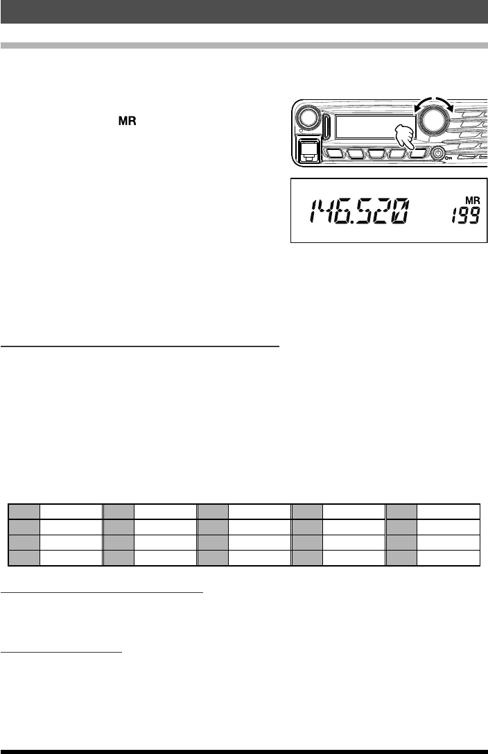
1. Press the [V/M(MW)] key, repeatedly if nec-
essary, until the “ ” icon and a memory
channel number appear on the display; this
indicates that the “Memory Recall” mode is
now engaged.
2. When more than one memory has been
stored, use the DIAL knob to select any of
the programmed memories for operation.
VOL
DIAL
DW MW
SETUP
REV V/MMHz
SQL TXPO
Note: Alternatively, the microphone [UP] or [DWN] button may be used to step or scan
through the available memories. When using the microphone buttons, press the
button momentarily to move one step up or down; press and hold the [UP] or
[DWN] button for one second to begin memory scanning.
Memory Recall from the Microphone Keypad
While operating in the Memory Recall mode, the keypad of the MH-48A6JA Microphone
may be used for direct recall of memory channels.
To do this, enter the desired Channel Number on the keypad and then press the [#] key.
For example:
To recall Memory Channel “5”, press [5] à [#]
To recall Memory Channel “123”, press [1] à [2] à [3] à [#]
You may also recall Programmable Memory Scan (PMS) channels (“L0/U0” through “L9/
U9”) by entering the channel numbers listed in the below table:
L1 201 L3 205 L5 209 L7 213 L9 217
U1 202 U3 206 U5 210 U7 214 U9 218
L2 203 L4 207 L6 211 L8 215 L0 219
U2 204 U4 208 U6 212 U8 216 U0 220
Moving Memory Data to the VFO
Data stored on memory channels can easily be moved to the VFO.
Note: For details, refer to the Advanced Manual (download from the Yaesu website).
Memory Only Mode
Once memory channel programming has been completed, you may place the radio in a
“Memory Only” mode, whereby VFO operation is impossible.
Note: For details, refer to the Advanced Manual (download from the Yaesu website).
Application for FCC / IC
FCC ID: K6620523X51 / IC: 511B-20523X51
24
Memory Operation
FTM-3100R Operating Manual
Masking Memories
There may be situations where you want to “Mask” memories so they are not visible
during memory selection or scanning. (except for Memory Channel “1”, the Priority Chan-
nel, and the Home Channel).
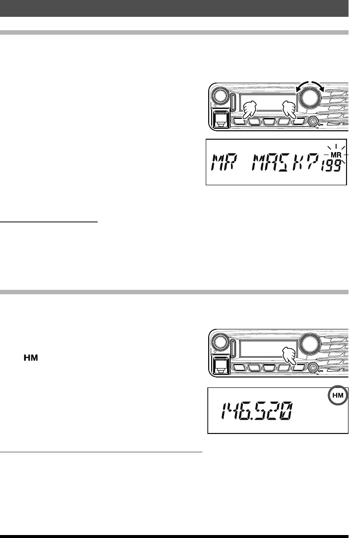
1. In the Memory Recall mode, press and hold
the [V/M(MW)] key for one second, then
rotate the DIAL knob to select the memory
channel you wish to mask.
2. Press the [SQL] key.
The erase confirmation screen appears.
3. Press the [SQL] key.
The previously selected memory will be
“masked”.
VOL
DIAL
DW MW
SETUP
REV
SQL TXPO V/MMHz
Note: Press any key, other than
[SQL], to cancel the memory mask.
Unmasking Memories
1. To Unmask a hidden memory, in the Memory Recall mode, press and hold the
[V/M(MW)] key for one second.
2. Rotate the DIAL knob to select the masked memory number.
3. Press the [SQL] key to restore the memory channel data.
HOME Channel Memory
A convenient one-touch “Home” channel memory is available to simplify returning to an
often used frequency.
To recall the Home channel, just press the
[V/M(MW)] key, repeatedly if necessary, until
the “ ” icon appears on the display; this
indicates that the Home Channel has been
recalled.
Note: When shipped from the factory, the
Home Channel is set to 146.520 MHz
(USA version) or 144.000 MHz (EXP
version).
VOL
DIAL
DW MW
SETUP
REV V/MMHz
SQL TXPO
Changing the frequency of the home channel
The default frequency setting of the home channel can be changed.
1. In the VFO mode, tune to the desired Home channel frequency.
2. Press and hold the [V/M(MW)] key for one second, and then press the [REV(DW)] key.
The overwrite confirmation screen appears.
3. Press the [REV(DW)] key.
The home channel frequency is overwritten.
Application for FCC / IC
FCC ID: K6620523X51 / IC: 511B-20523X51
25FTM-3100R Operating Manual
Scanning
Basic Scanner Operation
Before activating the scanner, make sure that the Squelch is set to silence the back-
ground noise when no signal is present. Scanning is not possible while the Squelch is
open (if noise or signals are being heard).
Scanning may be started or stopped using the micro-
phone [UP] or [DWN] button.
The following techniques are used for scanning:
r in the VFO mode, press and hold either the [UP]
or [DWN] button for one second, to start upward or
downward scanning of the band.
r In the Memory mode, press and hold either the
[UP] or [DWN] button for one second to start chan-
nel scanning toward a higher or lower-numbered
memory channel, respectively.
LOCK
P3
P2
P1
7
1
4
8
2
0
5
9
B
A
C
D
3
6
P4
LAMP
DTMF MICROPHONE
MH-48
ABC
JKL
TUV
GHI
PQRS
DEF
MNO
WXYZ
MIC
DWN UP
r Scanning pauses when a signal opens the squelch, and the decimal point on the dis-
play will blink. You can choose one of three scan-resume modes (described later).
r
To halt the scan manually, the easiest way is to push the PTT switch on the microphone
momentarily (no transmission will occur while you are scanning). The scan may also be
halted manually by pressing the microphone [UP] or [DWN] button, or the [V/M(MW)] key.
Scan Resume Options
Select which of the three resume scan modes is to be performed after the scanning stops.
Note: For details, refer to the Advanced Manual (download from the Yaesu website).
Memory Skip Scanning
Memory channels which you do not want to receive can be skipped during scanning.
Note: For details, refer to the Advanced Manual (download from the Yaesu website).
Preferential Memory Scan
Set up a “Preferential Scan List” of channels which you can “flag” within the memory system.
Note: For details, refer to the Advanced Manual (download from the Yaesu website).
Programmable Memory Scan (PMS)
Using the dedicated PMS memory channels, only the frequencies within the specified
frequency range will be scanned.
Note: For details, refer to the Advanced Manual (download from the Yaesu website).
Priority Channel Scanning (Dual Watch)
Scanning features include a two-channel scanning capability which allows you to operate
on a VFO, Memory channel, or Home channel, while periodically checking a user defined
Memory Channel for activity.
Note: For details, refer to the Advanced Manual (download from the Yaesu website).
Application for FCC / IC
FCC ID: K6620523X51 / IC: 511B-20523X51
26 FTM-3100R Operating Manual
Reset Procedure/Clone
Reset Procedure
In some instances of erratic or unpredictable operation, the cause may be corruption of
data in the microprocessor (due to static electricity, etc.). If this happens, resetting the
microprocessor may restore normal operation. Note that all memories will be erased if
you do a complete microprocessor reset, as described below.
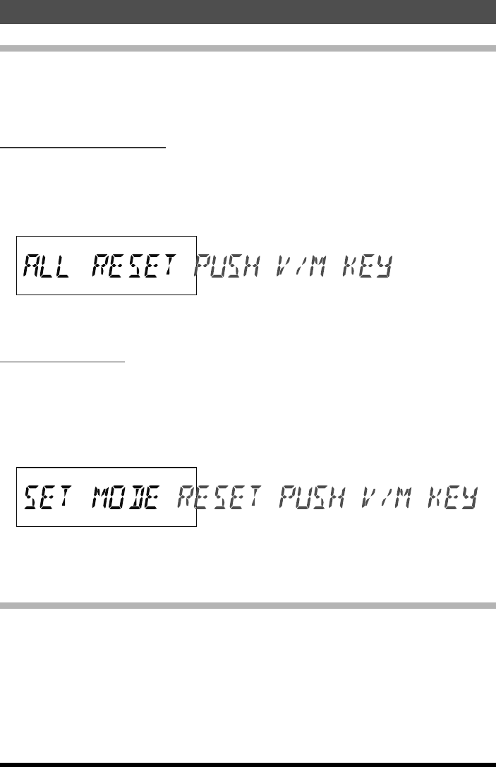
Microprocessor Resetting
To clear all memories and other settings to factory defaults:
1. Turn the radio OFF.
2. Press and hold the [TXPO], [MHz(SETUP)], and [V/M(MW)] keys while turning the
radio on. The “ALL RESET PUSH V/M KEY” notation will scroll on the display.
3. Press the [D/M(MW)] key momentarily to reset all settings to their factory defaults
(press any other key to cancel the Reset procedure).
Set Mode Resetting
To reset the Set (Menu) mode settings to their factory defaults, while leaving other set-
tings unchanged:
1. Turn the radio OFF.
2. Press and hold the [TXPO] and [MHz(SETUP)] keys while turning the radio on. The
“SET MODE RESET PUSH V/M KEY” notation will scroll on the display.
3. Press the [D/M(MW)] key momentarily to reset the Set (Menu) mode settings to their
factory defaults (press any other key to cancel the Reset procedure).
Clone
The FTM-3100R includes a convenient “Clone” feature, which allows the memory and
configuration data from one transceiver to be transferred to another FTM-3100R.
This can be particularly useful when configuring a number of transceivers for a public
service operation.
Note: For details, refer to the Advanced Manual (download from the Yaesu website).
Application for FCC / IC
FCC ID: K6620523X51 / IC: 511B-20523X51

27FTM-3100R Operating Manual
Miscellaneous Settings
Programming the Key Assignments
Default FTM-3100R key functions have been assigned to the Microphone’s [P1]/[P2]/[P3]/
[P4] keys at the factory. The user may change these key function assignments, if quick
access to another function is desired.
Note: For details, refer to the Advanced Manual (download from the Yaesu website).
Keyboard Beeper
A key/button beeper provides useful audible feedback whenever a key/button is pressed.
If you want to turn the beeper off (or back on again).
Note: If you want to turn the beeper off (or back on again), see Setup Menu Item “3 BEP
KEY” on page 29.
Display Brightness
You can adjust the display brightness.
Note: See Setup Menu Item “16 LCD DMMR” on page 30.
Time-Out-Timer (TOT)
The “Time-Out Timer” (TOT) feature is designed to force the transceiver into the “receive”
mode after a preset time period of continuous transmission (the default is 3 minutes).
Note: See Setup Menu Item “39 TOT” on page 31.
Automatic Power Off (APO)
The “Automatic Power-Off” (APO) feature will turn the radio completely off after a user
defined period of PTT or key/button inactivity.
Note: See Setup Menu Item “1 APO” on page 29.
Busy Channel Lock-Out (BCLO)
The BCLO feature prevents the transmitter from being activated whenever a signal strong
enough to break through the “noise” squelch is present on the frequency.
Note: See Setup Menu Item “2 BCLO” on page 29.
TX Deviation Level
You can reduce the receiver bandwidth and transmit deviation when operating on closely
spaced frequencies (channel spacing of 12.5 or 15 kHz). The reduced transmitter devia-
tion will minimize adjacent channel interference to other users.
Note: See Setup Menu Item “45 W/N DEV” on page 31.
MIC Gain Setting
At the factory, the microphone gain has been programmed so that it should be satisfac-
tory for the supplied MH-48A6JA Microphone. If you use an after-market microphone or
connect a TNC, you may wish to set a different Mic Gain level.
Note: See Setup Menu Item “18 MIC GAIN” on page 30.
Application for FCC / IC
FCC ID: K6620523X51 / IC: 511B-20523X51

28
Miscellaneous Settings
FTM-3100R Operating Manual
Displaying the Supply Voltage
Display the Power Supply voltage.
Note: See Setup Menu Item “8 DC VOLT” on page 29.
Displaying the Temperature
Indicates the current temperature inside the transceiver’s case.
Note: See Setup Menu Item “37 TEMP” on page 30.
Band Edge Beeper
The FTM-3100R will automatically “beep” when the receiver’s band edge is encountered
during scanning (either in standard VFO scanning or during PMS operation). You may
additionally enable this feature (band edge beeper) when the frequency reaches the band
edge while selecting the VFO frequency manually, using the DIAL knob.
Note: For details, refer to the Advanced Manual (download from the Yaesu website).
Application for FCC / IC
FCC ID: K6620523X51 / IC: 511B-20523X51
29FTM-3100R Operating Manual
Setup (Menu) Mode
The FTM-3100R Setup (Menu) mode, already described in parts of many previous
chapters, is easy to activate and set. It may be used for configuration of a wide variety
of transceiver parameters, some of which have not been detailed previously. Use the
following procedure to activate the Setup (Menu) mode:
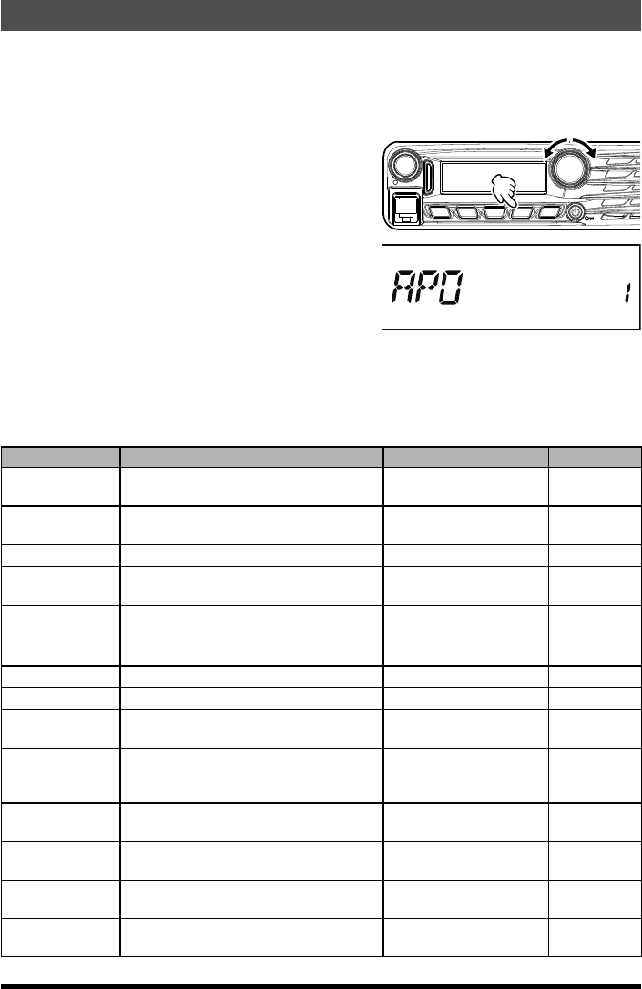
1. Press and hold the [MHz(SETUP)] key for
one second to enter the Setup menu.
2. Rotate the DIAL knob to select the Menu
Item to be adjusted.
3. Press the [MHz(SETUP)] key momentarily
to enable adjustment of the selected Menu
item, and then rotate the DIAL knob to per-
form the actual adjustment.
4. After completing your selection and adjust-
ment, press and hold the [MHz(SETUP)] key
for one second to exit the Setup menu and
resume normal operation.
VOL
DIAL
DW MW
SETUP
REV
SQL TXPO V/MMHz
Note: For details, refer to the Advanced Manual (download from the Yaesu website).
Menu Item Function Available Values Default
1: APO Enables/Disables the Automatic Power
Off feature.
0.5H to 12H (0.5H step)/
OFF OFF
2: BCLO Enables/Disables the Busy Channel
Lock-Out feature. ON/OFF OFF
3: BEP KEY Enables/Disables the key beeper. KEY+SCAN/KEY/OFF KEY+SCAN
4: BEP EDGE Enables/Disable the Band-edge beeper
while scanning. ON/OFF OFF
5: BEP STBY Enables/Disable the Standby beep ON/OFF ON
6: BELL Selects the CTCSS/DCS/EPCS Bell
Ringer repetitions. 1 to 20/CONTINUE/OFF OFF
7: CLK TYPE Shifting of the CPU clock frequency. A/B A
8: DC VOLT Indicates the DC Supply Voltage. --- ---
9: DCS CODE Setting of the DCS code. 104 standard DCS
codes 023
10: DCS INV
Select a combination of DCS inversion
codes in terms of communication direc-
tion.
NORMAL/INVERT/
BOTH NORMAL
11: DT AUTO Enables/Disables the DTMF Autodialer
feature. MANUAL/AUTO MANUAL
12: DT DELAY Setting of the DTMF Autodialer TX Delay
Time. 50/250/450/750/1000 450 MS
13: DT SET Loading of the DTMF Autodialer Memo-
ries. --- ---
14: DT SPEED Setting of the DTMF Autodialer Sending
Speed. 50/100 50 MS
Application for FCC / IC
FCC ID: K6620523X51 / IC: 511B-20523X51

30
Setup (Menu) Mode
FTM-3100R Operating Manual
Menu Item Function Available Values Default
15: DW RVRT Enables/Disables the “Priority Channel
Revert” feature. ON/OFF OFF
16: LCD DMMR Setting of the front panel display’s illumi-
nation level. LEVEL 1/2/3/4 LEVEL 4
17: LOCK Selects the Control Locking Lockout
combination.
KEY+DIAL/PTT/
KEY+PTT/DIAL+PTT/
ALL/KEY/DIAL
KEY+DIAL
18: MIC GAIN Adjust the microphone gain level. LEVEL 1 to 9 LEVEL 5
19: MEM NAME Programming an Alpha/Numeric label for
a Memory Channel. --- ---
20: MW MODE Selects the method of selecting of chan-
nels for Memory Storage. NEXT CH/LOWER CH NEXT CH
21: OPEN MSG Selects the Opening Message that ap-
pears when the radio is powered ON. OFF/DC/MESSAGE MESSAGE
22: PAG CD-R
Setting the Receiver Pager Code for
the Enhanced CTCSS Paging & Code
Squelch function.
--- 05 47
23: PAG CD-T
Setting the Transmitting Pager Code for
the Enhanced CTCSS Paging & Code
Squelch function.
--- 05 47
24: PRG P1 Programming the function assigned to
Microphone’s [P1] key.
SQL OFF
HOME
WX CH
CD SRCH
SCAN
T CALL
TX POWER
DIG/ANA
GM
Setup Menu Item #1 to
45
SQL OFF
25: PRG P2 Programming the function assigned to
Microphone’s [P2] key. HOME
26: PRG P3 Programming the function assigned to
Microphone’s [P3] key. CD SRCH
27: PRG P4 Programming the function assigned to
Microphone’s [P4] key. ø
28: RF SQL Adjusts the RF Squelch threshold level. OFF/S1 to S8 OFF
29: RPT ARS Activates/Deactivates the Automatic Re-
peater Shift feature. ON/OFF ON
30: RPT FREQ Sets the magnitude of the Repeater Shift. 0.00 - 150.00 (MHz) 0.60 MHz
31: RPT SFT Sets the Repeater Shift direction. -RPT/+RPT/SIMPLEX SIMPLEX
32: SCAN RSM Selects the Scan Resume mode.
BUSY
/
HOLD
/2-10 (SEC) 5.0 SEC
33: SCAN SKP Selects the Memory Scan mode. OFF/SKIP/SELECT OFF
34: SQL EXP Sets the squelch type separately for
transmission and reception. ON/OFF OFF
35: SQL TYPE Selects the Tone Encoder and/or Decod-
er mode.
TONE/TSQL/DCS/
RV TONE/PAGER/OFF OFF
36: STEP Sets the Synthesizer steps. AUTO/5/6.25/10/12.5/15
/20/25/50/100 (kHz) AUTO
37: TEMP Indicates the current temperature inside
the transceiver’s case. --- ø
38: TONE FRQ Setting of the CTCSS Tone Frequency. 67.0 to 254.1 (Hz) 100.0 HZ
Application for FCC / IC
FCC ID: K6620523X51 / IC: 511B-20523X51

31
Setup (Menu) Mode
FTM-3100R Operating Manual
Menu Item Function Available Values Default
39: TOT Sets the Time-Out Timer. 0.5 to 10.0 (MIN)/OFF 3.0 MIN
40: TS MUTE
Enables/Disables the receiver audio out-
put while the Tone Search Scanner is
activated.
ON/OFF ON
41: TS SPEED Selects the Tone Search Scanner speed. FAST/SLOW FAST
42: VER DISP Displays the transceiver software version CPU x.xx
DSP x.xx ---
43: WX ALERT Enables/Disables the Weather Alert fea-
ture. ON/OFF OFF
44: WX VOL Selects the audio output level of the
Weather Alert. NOR VOL/MAX VOL NOR VOL
45: W/N DEV Reduction of the Microphone Gain/Devia-
tion and receiver bandwidth. WIDE/NARROW WIDE
ø: Depends on the transceiver version.
Application for FCC / IC
FCC ID: K6620523X51 / IC: 511B-20523X51
32 FTM-3100R Operating Manual
Maintenance
Care and maintenance
Turn the power OFF before wiping away any dust and stains on the transceiver with a dry
soft cloth. For stubborn stains, slightly moisten a soft cloth and wring it out before using it
to wipe away the stains.
Caution: Never use washing detergents and organic solvents (thinner, benzene, etc.).
Doing so may result in paint flaking or damage to the transceiver finish.
Replacing the fuse
When the fuse of the DC power supply cable blows and the transceiver becomes
inoperable, correct the cause of the problem, and then replace the fuse with a new one of
the correct (25 Amp) rating.
Caution: When replacing the fuse, be sure to disconnect the power supply cable from
the transceiver and from the external DC power supply.
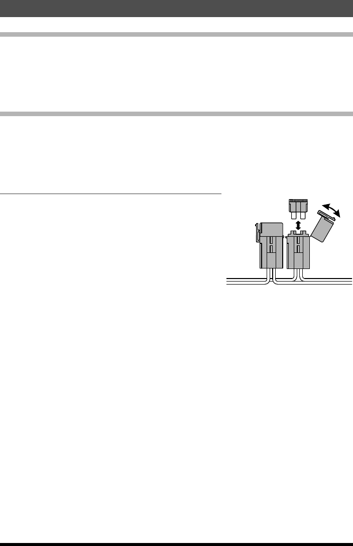
Replacing the fuse of the DC power supply cable
1. Prepare a new fuse.
Use a fuse with a rating of 25 A.
Caution: Never attempt to use a fuse that is
not of the specified rating
2. Open the fuse holder as shown in the dia-
gram on the right.
3. Remove the blown fuse.
4. Attach the new fuse.
5. Close the fuse holder.
Application for FCC / IC
FCC ID: K6620523X51 / IC: 511B-20523X51

33FTM-3100R Operating Manual
Specifications
General
Frequency Range: Tx 144 - 148 MHz
Rx 136 - 174 MHz
Channel Step: 5/6.25/10/12.5/15/20/25/50/100 kHz
Standard Repeater Shift: ±600 kHz
Frequency Stability: ±10 ppm [-4 °F to +140 °F (-20 °C to +60 °C)]
Modes of Emission: F3E
Antenna Impedance: 50 Ohms, unbalanced
Supply voltage: 13.8 V DC ±15%, negative ground
Current Consumption (typical): Rx: less than 0.7 A, less than 0.5 A (squelched)
Tx: 15 A (65 W) /10 A (30 W) /5 A (5 W)
Operating Temperature Range: -4° F to +140° F (-20° C to +60° C)
Case Size (WxHxD): 6.1” x 1.7” x 6.1” (154 x 43 x 155 mm) (w/o knobs)
Weight (Approx.): 2.86 lb (1.3 kg)
Transmitter
Output Power: 65/30/5 W
Modulation Type: Variable Reactance
Maximum Deviation: ±5 kHz (Wide)
±2.5 kHz (Narrow)
Spurious Radiation: Better than -60 dB
Microphone Impedance: 2k Ohms
Receiver
Circuit Type: Double Conversion Superheterodyne
Ifs: 1st 47.25 MHz, 2nd 450 kHz
Sensitivity (for 12dB SINAD): 0.20 μV (Ham band, wide)
0.22 μV (Ham band, narrow)
Selectivity (–6/–60dB): 12 kHz/28 kHz
Maximum AF Output: 3 W @ 13.8 V, 10% THD
Rated values are at normal temperature and pressure.
Ratings and specifications are subject to change without notice.
Application for FCC / IC
FCC ID: K6620523X51 / IC: 511B-20523X51

34 FTM-3100R Operating Manual
1. Changes or modifications to this device that are not expressly approved by YAESU MUSEN could
void the user’s authorization to operate this device.
2. This device complies with part 15 of the FCC Rules. Operation is subject to the following two
conditions: (1) This device may not cause harmful interference, and (2) this device must accept any
interference including received, interference that may cause undesired operation.
3. The scanning receiver in this equipment is incapable of tuning, or readily being altered, by the User
to operate within the frequency bands allocated to the Domestic public Cellular Telecommunications
Service in Part 22.
This device complies with Industry Canada license-exempt RSS standard(s). Operation is subject
to the following two conditions: (1) this device may not cause interference, and (2) this device must
accept any interference, including interference that may cause undesired operation of the device.
Le présent appareil est conforme aux CNR d’Industrie Canada applicables aux appareils radio
exempts de licence. L’exploitation est autorisée aux deux conditions suivantes : (1) l’appareil ne doit
pas produire de brouillage, et (2) l’utilisateur de l’appareil doit accepter tout brouillage radioélectrique
subi, même si le brouillage est susceptible d’en compromettre le fonctionnement.
DECLARATION BY MANUFACTURER
The Scanner receiver is not a digital scanner and is incapable of being converted or modified to a
digital scanner receiver by any user.
WARNING: MODIFICATION OF THIS DEVICE TO RECEIVE CELLULAR RADIOTELEPHONE
SERVICE SIGNALS IS PROHIBITED UNDER FCC RULES AND FEDERAL LAW.
CAN ICES-3 (B) / NMB-3 (B)
This equipment has been tested and found to comply with the limits for a Class B digital device,
pursuant to part 15 of the FCC Rules. These limits are designed to provide reasonable protection
against harmful interference in a residential installation. This equipment generates uses and can
radiate radio frequency energy and, if not installed and used in accordance with the instructions, may
cause harmful interference to radio communications. However, there is no guarantee that interference
will not occur in a particular installation.
If this equipment does cause harmful interference to radio or television reception, which can
be determined by turning the equipment off and on, the user is encouraged to try to correct the
interference by one or more of the following measures:
r Reorient or relocate the receiving antenna.
r Increase the separation between the equipment and receiver.
r Connect the equipment into an outlet on a circuit different from that to which the receiver is
connected.
r Consult the dealer or an experienced radio/TV technician for help.
Application for FCC / IC
FCC ID: K6620523X51 / IC: 511B-20523X51
Application for FCC / IC
FCC ID: K6620523X51 / IC: 511B-20523X51

Copyright 2016
YAESU MUSEN CO., LTD.
All rights reserved.
No portion of this manual
may be reproduced
without the permission of
YAESU MUSEN CO., LTD.
Printed in Japan
1602-0O
YAESU MUSEN CO., LTD.
Tennozu Parkside Building
2-5-8 Higashi-Shinagawa, Shinagawa-ku, Tokyo 140-0002 Japan
YAESU USA
6125 Phyllis Drive, Cypress, CA 90630, U.S.A.
YAESU UK
Unit 12, Sun Valley Business Park, Winnall Close
Winchester, Hampshire, SO23 0LB, U.K.
*EH052N150*
EH052N150
Application for FCC / IC
FCC ID: K6620523X51 / IC: 511B-20523X51