Yaesu Musen 20605X20 Analog Scanning Receiver User Manual part 3
Yaesu Musen Co., Ltd. Analog Scanning Receiver part 3
Contents
- 1. User Manual - part 1
- 2. User Manual - part 2
- 3. User Manual - part 3
- 4. User Manual - part 4
User Manual - part 3

21
Preparation
Preparing the Battery Pack/External Power Supply
Connecting an External Power Supply for Use in Vehicle
The optional external power supply adapter
with a cigarette lighter plug (SDD-13) allows
the transceiver to be used in a vehicle�
1 Turn off the transceiver�
2 Insert the plug of the external power
supply adapter with a cigarette lighter plug
(SDD-13) in the EXT DC IN jack of the
transceiver�
3 Insert the cigarette lighter plug of the
external power supply adapter in the
cigarette lighter socket of the vehicle�
Cautions
yThe SDD-13 is compatible with a 12 V DC cigarette lighter socket� Do not connect the SDD-13 to
the 24 V DC cigarette lighter socket�
yUse the transceiver at the minimum required transmission power level to prevent overheating�
yDo not continue transmission for a prolonged period of time� The transceiver may overheat,
resulting in malfunction or burns�
yIf you operate the transceiver for 7 hours or longer, it is recommended that you remove the battery
pack and install the optional battery case (FBA-39)�
yRecharging the fully-charged battery pack repeatedly can shorten its service life� Be extremely
careful not to do so when you operate the transceiver when using an external power supply�
yWhile charging the battery pack, protect the transceiver from water�
yCharge the battery pack in a place where the ambient temperature is +5 °C to +35 °C (+41 °F to
+95 °F).
yIf the terminal or electrode of the battery pack is dirty, the transceiver can malfunction due to poor
contact, resulting in overheating or rupture� If the terminal or electrode gets dirty, clean it using a dry
cloth or cotton swab�
Tips
• The battery pack can be charged within approximately 8 hours using the external power supply
(approximately 8 hours to charge the optional battery pack FNB-102LI)� If the battery pack is
charged with the transceiver turned on, the charging time increases slightly�
• When the battery pack has been fully charged, charging stops automatically�
• The external power supply can be used with the battery case installed�
• If you connect the transceiver to the external power supply with the transceiver turned off,
“CONNECTED TO EXTERNAL POWER” appears on the LCD, and about 20 seconds later
“BATTERY NOT INSTALLED” appears�
To cigarette lighter socket
of vehicle
EXT DC IN jack
External power supply
adapter with a cigarette
lighter plug SDD-13(optional)
T�B�D�
Application for FCC / IC
FCC ID: K6620605X20
IC: 511B-20605X20

22
Preparation
Preparing the Battery Pack/External Power Supply
Connecting to an External Power Supply Using a Power Cable
The optional power cable (E-DC-6) allows the transceiver to be connected to an external
power supply�
1 Turn off the transceiver�
2 Connect the optional external power supply
cable (E-DC-6) to an external power supply�
Remarks • Connect the red/black wire or white/red
wire to the positive (+) terminal of the
external power supply and the black wire
to the negative (−) terminal.
• Set the voltage of the external power
supply to 12 to 14 V�
3 Insert the plug of the external power supply in
the EXT DC IN jack of the transceiver�
Cautions
yWhen you use the transceiver with the external power supply cable (E-DC-6) connected to an
external power supply, pay attention to the following:
• The power supply voltage must be between 12 V and 14 V�
If the voltage exceeds 14 V, the high voltage protection function is activated to disable high-power
transmission� L3 (2�5 W) is selected automatically to reduce the transmission power� If the voltage
exceeds 16 V, malfunctions such as damage to the electric circuits of the transceiver may result�
Take extra care�
• Connect the red/black wire or white/black wire of the external power supply cable (E-DC-6) to the
positive (+) terminal of the external power supply and the black wire to the negative (−) terminal.
• Use an external power supply having sufficient current capacity (3 A or more)�
• If the transceiver is used with supplied antenna connected, the external power supply can
malfunction, resulting in a failure� If you use an external power supply, remove the supplied
antenna and connect an external antenna� Place the external power supply sufficiently away from
the transceiver�
yUse the transceiver at the minimum required transmission power level to prevent overheating�
yDo not continue transmission for a prolonged period� The transceiver may overheat, resulting in
malfunction or burn�
yIf you operate the transceiver for 7 hours or longer, it is recommended that you remove the battery
pack and install the optional battery case (FBA-39)�
yRecharging the fully-charged battery pack repeatedly can shorten its service life� Be extremely
careful not to do so when you operate the transceiver using an external power supply�
yWhile charging the battery pack, protect the transceiver from water�
yCharge the battery pack in a place where the ambient temperature is +5 °C to +35 °C (+41 °F to
+95 °F).
yIf the terminal or electrode of the battery case is dirty, the transceiver may malfunction due to poor
contact, resulting in overheating or rupture� If the terminal or electrode gets dirty, clean it using a dry
cloth or cotton swab�
Connect the external
antenna. External power supply
External power supply
cable E-DC-6
(optional)
T�B�D�
Application for FCC / IC
FCC ID: K6620605X20
IC: 511B-20605X20

23
Preparation
Preparing the Battery Pack/External Power Supply
Tips
• The battery pack can be charged within approximately 8 hours using the external power supply
(approximately 8 hours to charge the optional battery pack FNB-102LI)� If the battery pack is
charged with the transceiver turned on, the charging time increases slightly�
• The external power supply can be used with the battery case installed�
If you connect the transceiver to the external power supply with it turned off, “CONNECTED
TO EXTERNAL POWER” appears on the LCD, and about 20 seconds later, “BATTERY NOT
INSTALLED” appears�
Application for FCC / IC
FCC ID: K6620605X20
IC: 511B-20605X20

24
Preparation
Using a microSD Memory Card
Using a microSD memory card with the transceiver allows the following functions�
• Backing up information on the transceiver
• Saving memory information
• Saving data other than images
• Saving GPS log data
• Saving image data captured with the optional camera-equipped microphone (MH-
85A11U)
• Saving messages downloaded with the GM function or WIRES-X function
Usable microSD Memory Cards
This transceiver only supports the following capacity of microSD and microSDHD
memory cards�
• 2GB • 4GB • 8GB • 16GB • 32GB
Cautions when Using a microSD Memory Card
• Do not bend or place heavy objects on the microSD memory card�
• microSD memory cards formatted on other devices may not properly save information
when used with this transceiver� Format microSD memory cards again with this
transceiver when using memory cards formatted with another device�
• When saving data to a microSD memory card, do not remove the microSD memory
card or turn off the transceiver�
• Do not insert anything other than microSD memory card into the microSD memory
card slot of the transceiver�
• Do not attempt to forcefully remove mounted microSD memory card�
Mounting and Dismounting microSD Memory Card
1 Press and hold for over 1 second�
The transceiver will turn off�
Application for FCC / IC
FCC ID: K6620605X20
IC: 511B-20605X20
25
Preparation
Using a microSD Memory Card
2 Open the microSD cover on the side of the
transceiver�
3 Insert the microSD memory card into the card slot
until you hear a clicking sound (as shown in the
figure at the right)�
Cautions Ensure that the microSD memory card is facing
the proper direction when inserting it�
Do not touch the terminal of the microSD memory
card�
Do not push the microSD
memory card into this space.
4 Close the microSD cover�
5 Press and hold for over 1 second�
The transceiver will turn on� When the microSD
memory card is properly detected, lights on the
display�
Tip
Removing the microSD memory card
To remove the microSD memory card, as done in step 3 above,
push the memory card in until you hear a clicking sound, then
remove the memory card�
* Using the micro SD Card Clip makes it easy to remove the
micro SD memory card�
Caution
Do not turn off the transceiver while the data is being written to
the microSD memory card� Doing so may corrupt the data�
T�B�D�
T�B�D�
T�B�D�
T�B�D�
Application for FCC / IC
FCC ID: K6620605X20
IC: 511B-20605X20
26
Preparation
Using a microSD Memory Card
Formatting a microSD Memory Card
Format a new microSD memory card following the steps below before use�
Caution
Formatting a microSD memory card erases all data saved on it� If you are going to format the
microSD memory card you are using, be sure to check the data saved on it before formatting�
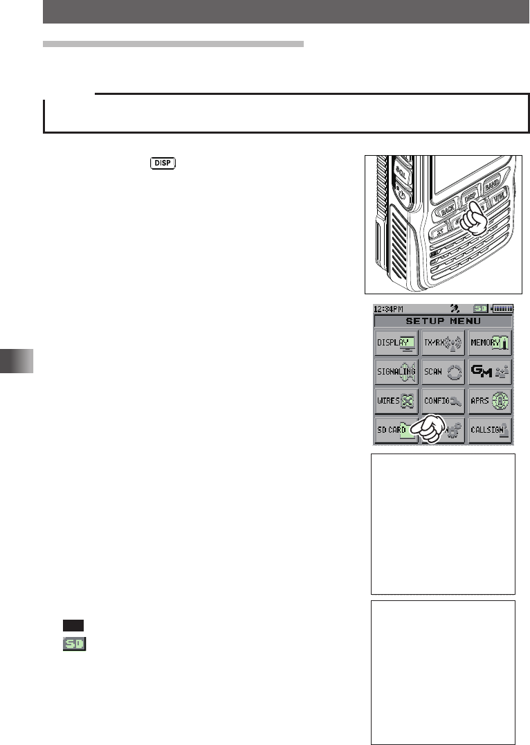
1 Press and hold for over 1 second�
The “SETUP MENU” screen appears�
2 Touch [SD CARD]�
3 Touch [FORMAT]�
[OK?] appears on the LCD�
4 Touch [OK]�
Tip To cancel formatting, select [Cancel]�
on the LCD blinks and formatting starts�
When formatting is completed, a beep sounds and
[Completed] appears on the LCD� T�B�D�
T�B�D�
Application for FCC / IC
FCC ID: K6620605X20
IC: 511B-20605X20
27
Basic Operation
Basic Operation
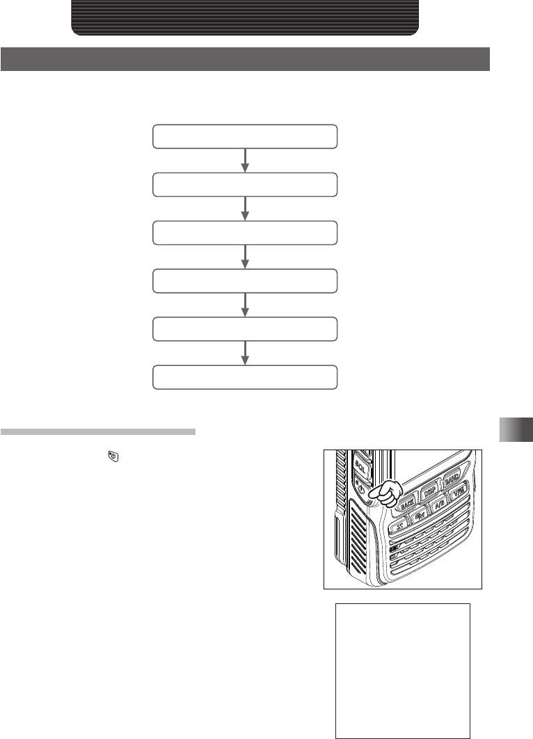
Performing Communication
Try communication using the transceiver in the analog communication mode� Follow the
procedure below:
Turn on the transceiver
Adjust the Volume Level
Select an Operating Band
Select a Frequency Band
Turn in to a Frequency
Perform Communication
Turning on the Transceiver
1 Press and hold for over 1 second�
When the transceiver is turned on for the first time
after purchase, the call sign input screen appears for
2 seconds� Then, the alphabet input screen appears�
From the second time, the opening screen appears
followed by the frequency screen� T�B�D�
Application for FCC / IC
FCC ID: K6620605X20
IC: 511B-20605X20
28
Basic Operation
Performing Communication
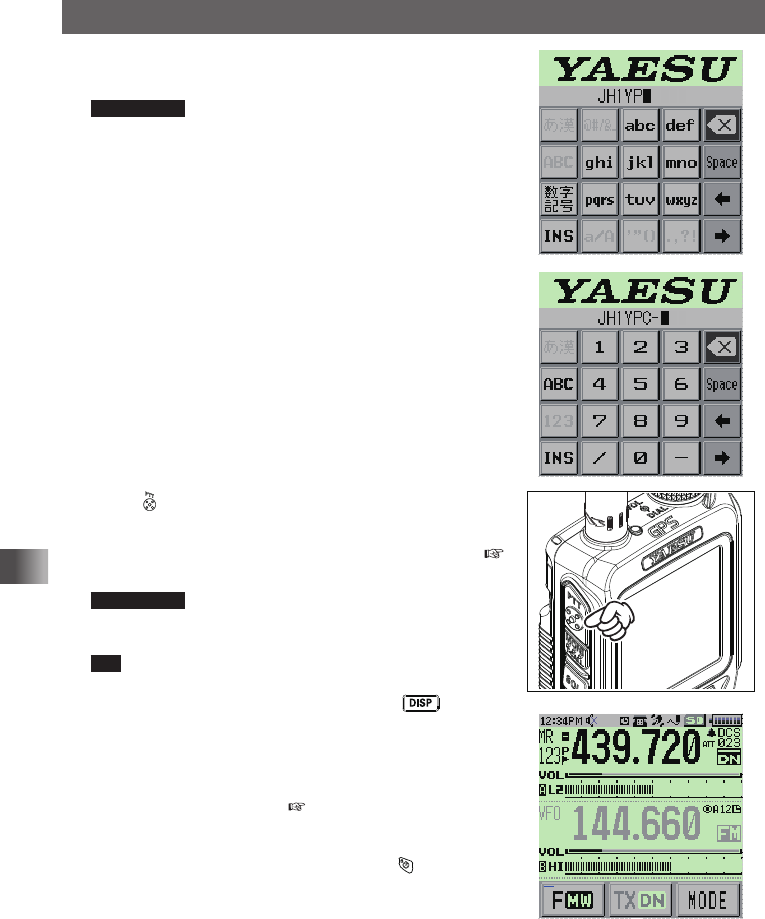
2 Input the call sign toggling the alphabet input screen
and number input screen�
Supplement The alphabet input screen can be switched to
the number input screen by touching [数字記号]�
The number input screen can be switched to the
alphabet input screen by touching [ABC]�
3 Press �
The call sign is set and the frequencies of both
A-band and B-band is displayed simultaneously� (
see page xx)
Supplement Factory settings are:
A-band (upper): 145�000 MHz
B-band (lower): 433�000 MHz
Tip You can change the information such as the power
supply voltage and the opening message displayed at
power-on� For example, press and hold for over 1
second to enter Set mode and then select [DISPLAY] →
[9 OPENING MESSAGE] to change the setting�
In addition, you can also set the transceiver to display
the reception frequency immediately without displaying
the opening message ( see page xx)�
yTurning off the Transceiver
To turn off the transceiver, press and hold for over 1
second�
メモリー書き込み中!A1
Application for FCC / IC
FCC ID: K6620605X20
IC: 511B-20605X20
29
Basic Operation
Performing Communication
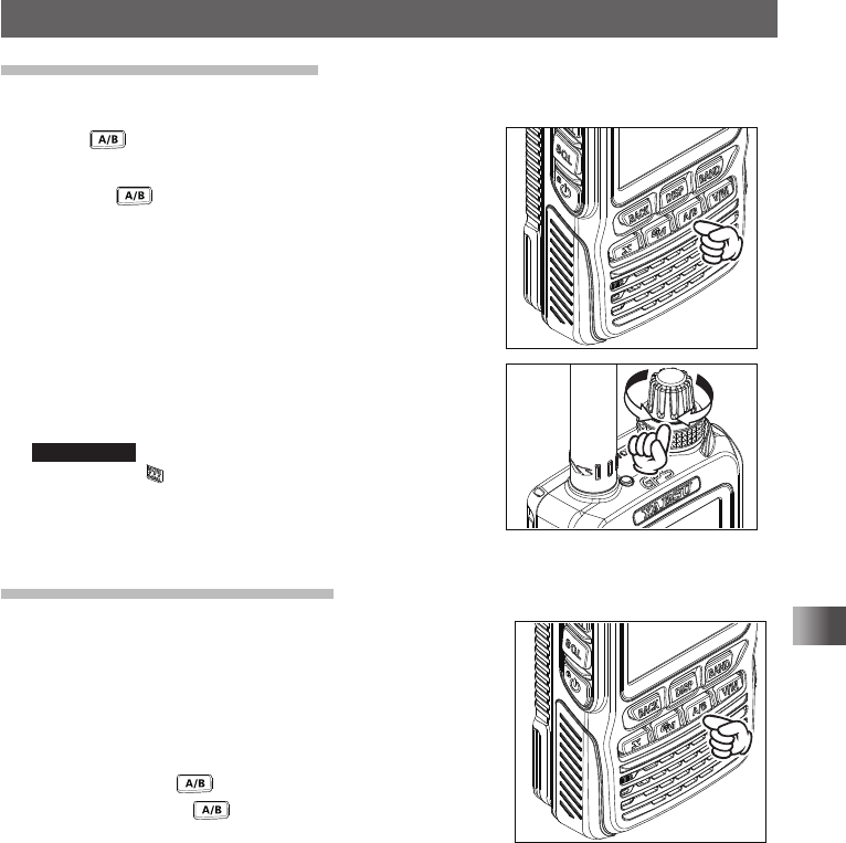
Adjusting the Volume Level
You can adjust the transceiver volume level for the A-band and B-band separately�
1 Press to select the band for which you want to
adjust the volume level�
Pressing each time toggles between the
A-band and B-band�
2 Rotate the VOL knob clockwise/counterclockwise
to adjust the volume level�
The [VOL] gauge moves right/left�
Supplement If no sound is heard from the speaker, press
and then adjust the volume level while
listening to white noise�
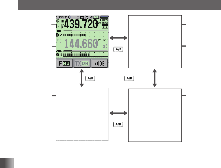
Toggling the Operating Band
Normally, 2 operating bands are displayed on the top half
and bottom half of the transceiver touch screen� This is
called Dual band�
With one of the bands selected, change the frequency
and radio wave form� The selected band is called
Operating band� The other band is called Sub-band�
Each time pressing toggles the operating band�
Pressing and holding for over 1 second displays
only the operating band which is called Mono-band�
On how to toggle operating bands, see the following
illustrations�
Application for FCC / IC
FCC ID: K6620605X20
IC: 511B-20605X20
30
Basic Operation
Performing Communication
A-band
(operating
band)
B-band
メモリー書き込み中!A1
Press and hold
for over
1 second
Press and hold
for over
1 second
A-band
B-band
(operating
band)
A-band
Mono-band
double size
characters
B-band
Mono-band
double size
characters
Press
Press
T�B�D� T�B�D�
T�B�D�
Application for FCC / IC
FCC ID: K6620605X20
IC: 511B-20605X20