Yaesu Musen 20605X20 Analog Scanning Receiver User Manual part 4
Yaesu Musen Co., Ltd. Analog Scanning Receiver part 4
Contents
- 1. User Manual - part 1
- 2. User Manual - part 2
- 3. User Manual - part 3
- 4. User Manual - part 4
User Manual - part 4
31
Basic Operation
Performing Communication
Tips
• On A-band, you can transmit and receive using the 144 MHz and 430 MHz Amateur radio bands�
• On B-band, you can transmit and receive using the 144 MHz and 430 MHz Amateur radio bands�
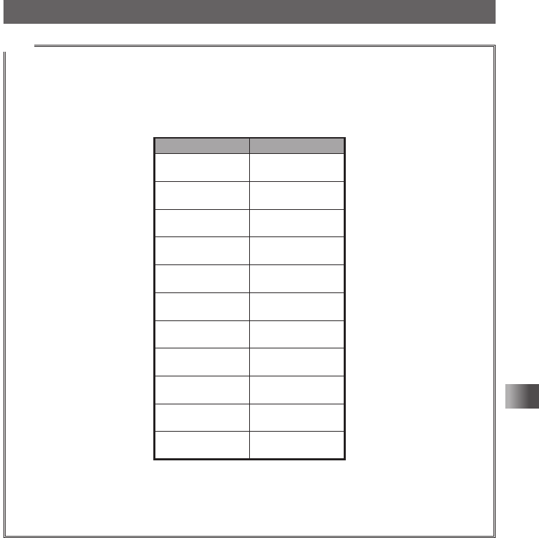
In addition, the frequencies on the chart below can be received on A-band and B-band�
Chart of A-band and B-band
reception frequencies
A-band B-band
1.8MHz - 30MHz
(SW band)
30MHz - 76MHz
(50 MHz band)
108MHz - 137MHz
(AIR band)
137MHz - 174MHz
(144 MHz band)
174MHz - 222MHz
222MHz - 420MHz
(INFO band (1))
420MHz - 470MHz
(430 MHz band)
470MHz - 770MHz
770MHz - 999MHz
(INFO band (2))
108MHz - 137MHz
(AIR band)
137MHz - 174MHz
(144 MHz band)
174MHz - 222MHz
222MHz - 420MHz
(INFO band (1))
420MHz - 470MHz
(430 MHz band)
470MHz - 580MHz
— —
— —
— —
76MHz - 108MHz
(FM BC Band) — —
0.5MHz - 1.8MHz
(AM BC Band) — —
• A-band and B-band can be received at the same time�
You can receive Amateur radio frequency while listening to the AIR band, or receive two Amateur
radio frequencies on the same frequency band at the same time (V+V/U+U: Dual frequency
reception on the same band)�
Application for FCC / IC
FCC ID: K6620605X20
IC: 511B-20605X20
32
Basic Operation
Performing Communication
Selecting a Frequency Band
You can select a frequency band to use for the A-band and B-band separately� The
frequency band can be selected by following the steps below�
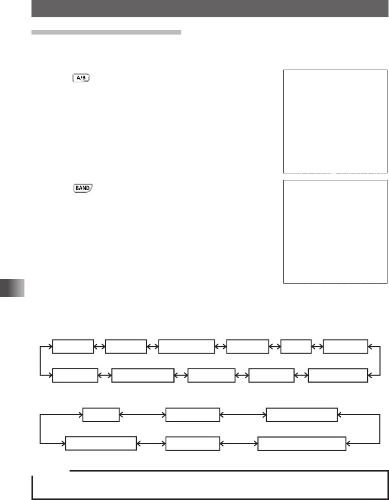
1 Press to select A-band�
メモリー書き込み中!A1
2 Touch to select your desired frequency band�
MENU DISPLAY 2'!A7723 TOP画面プリセットレシーバー!A1
TOP画面AF-DUAL表示'!A1 Band Scope'!A1
FUNCTION!A389 APRS Message list1'!A1
APRS Station list1'!A1
Available frequency bands differ depending on the band� The following frequency bands
can be used for A-band and B-band�
yFrequency band on A-band
Short Wave Band 50 MHz bandFM BC Band AIR band 144 MHz band
174MHz to 222MHz
Information
radio band (1)
430 MHz band
470MHz to 770MHz
Information
radio band (2)
AM BC Band
yFrequency band on B-band
AIR band 144MHz band 174MHz to 222MHz
Information radio band (1)
430MHz band
470MHz to 580MHz
Caution
Digital communication can be performed only on the A-band�
Digital communication cannot be performed on the B-band�
T�B�D�
T�B�D�
Application for FCC / IC
FCC ID: K6620605X20
IC: 511B-20605X20
33
Basic Operation
Performing Communication
Tips
• The frequency settings from the factory are:
A-band: 145�000 MHz B-band: 433�000 MHz
• In the default, Auto mode is set so that the transceiver can be automatically switched to the optimal
reception mode for the frequency bands�
Press and hold for over 1 second to switch the transceiver to Set mode, then touch, [TX/RX]
→ [1 MODE] → [3 RX MODE] to change mode ( see page xx)�
• For the relations between frequency bands and reception frequencies, see the table on page xx�
• You can also recall the home channel of each frequency band by touching [F MW] followed by
[HOME] ( see page xx)�
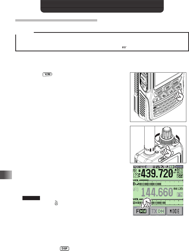
Tuning in to a Frequency
Tune in to your desired frequency using either of the following methods:
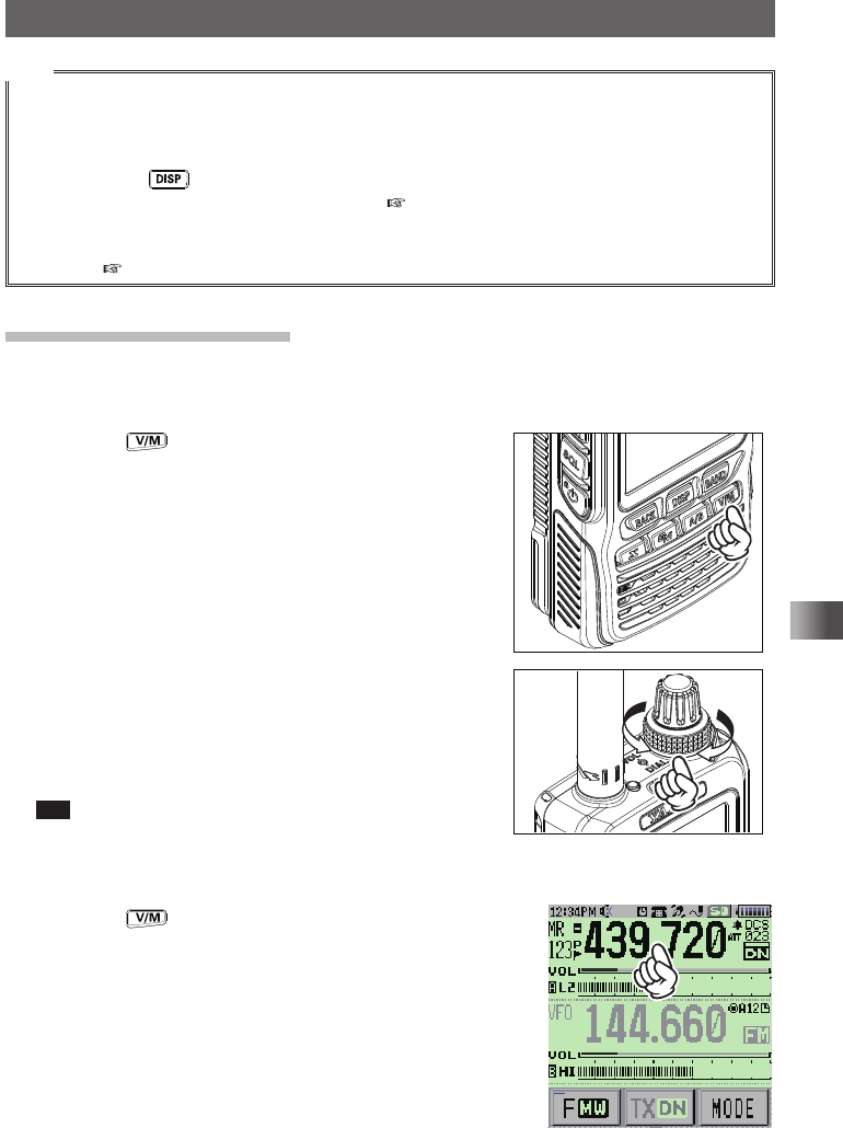
yRotating the DIAL to tune in to your desired frequency
1 Press the key to switch the transceiver to
VFO mode�
2 Rotate the DIAL to tune in to your desired
frequency�
Rotate clockwise: The frequency increases�
Rotate counterclockwise: The frequency
decreases�
Tip By touching [F MW] and rotating the DIAL, you can
tune in to the desired frequency in steps of 1 MHz�
yEntering your desired frequency directly using the numeric keys
1 Press the key to switch the transceiver to VFO
mode�
2 Touch the frequency displayed on the LCD�
The numeric keypad appears�
メモリー書き込み中!A1
Application for FCC / IC
FCC ID: K6620605X20
IC: 511B-20605X20
34
Basic Operation
Performing Communication
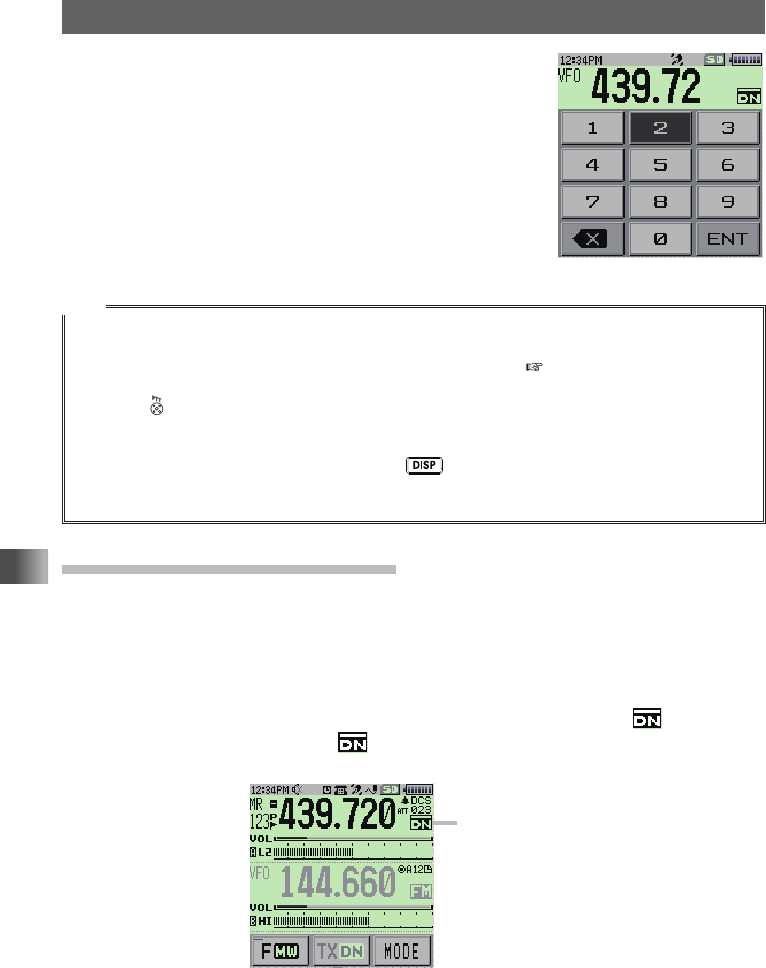
3 Enter the frequency using the numeric keys�
Example: To input 145�520 MHz
[1] → [4] → [5] → [5] → [2] → [ENT]
Example: To input 430�000 MHz
[4] → [3] → [ENT]
Tips
• In factory settings, Auto Step mode is set such that the transceiver is automatically switched to the
optimal frequency steps for the reception frequency�
You can also change frequency steps manually rotating the DIAL ( see page xx)�
• If you enter a wrong digit when entering a frequency using numeric keys, you can cancel it by
pressing �
• In factory settings, turning the DIAL further beyond the selected frequency band causes the
transceiver to switch to another frequency band�
To prevent this from happening, press and hold for over 1 second to switch to Set mode, then
touch [CONFIG] → [21 VFO MODE], and select “BAND” for repeatedly showing frequencies on the
same frequency band�
Selecting Communication Mode
yUsing AMS
This transceiver is equipped with AMS (Automatic Mode Select) which automatically
selects between 4 modes of transmission to fit the signal being received� Because the
transmission is automatically adjusted to that of the other station, not only C4FM digital
signals, but analog signals are also recognized automatically�
To utilize the AMS function, repeatedly touch [MODE] on the LCD until “ ” appears�
After receiving the signal, “DN” of “ ” will be changed according to the received
signal�
メモリー書き込み中!A1
Example of when
AMS is displayed
yFixing the Communication Mode
To fix the communication mode for operation, touch [MODE] on the LCD to switch the
communication mode�
Touching [MODE] on the LCD each time toggles the communication mode as follows�
Application for FCC / IC
FCC ID: K6620605X20
IC: 511B-20605X20
35
Basic Operation
Performing Communication
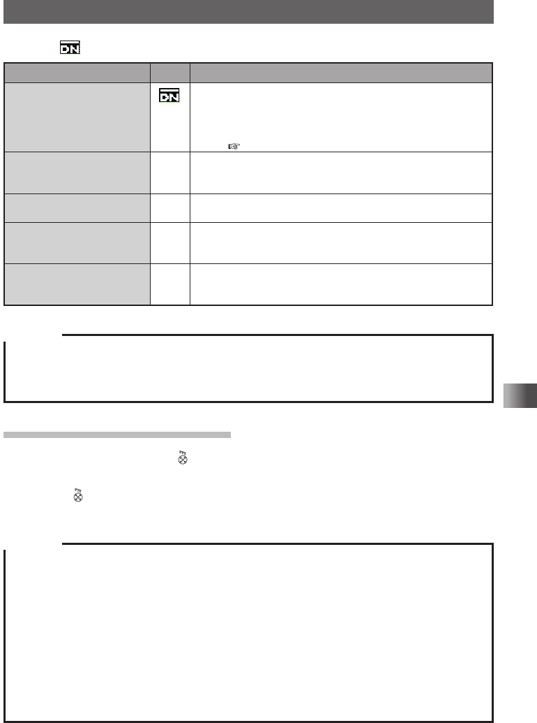
[ (AMS)] → [DN (V/D mode)] → [VW (FR mode)] → [FM (analog)]
Operation mode Icon Description of Modes
AMS
(Automatic Mode Select)
Transmission mode is automatically selected from 4 types according
to the signal received�
(“DN” part differs depending on the received signal�)
The AMS function operation can be changed with the Set mode
setting ( see page xx)�
V/D Mode
(Voice/Data simultaneous
transmission mode)
DN Calls are less prone to interruptions due to detection and correction
of voice signals during digital voice signal transmission� This is the
standard mode for C4FM FDMA Digital�
Voice FR Mode
(Voice Full Rate Mode)
VW High speed data communication using entire 12�5 kHz band�
Enables high-quality voice communication�
Data FR Mode (High Speed
Data Communication Mode)
DW Digital voice data transmission using the entire 12�5 kHz band�
The transceiver automatically switches to this mode during image
transmission�
Analog FM Mode FM Analog communication using FM mode�
Effective when the signal is weak and audio is susceptible to
interruption in digital mode�
Cautions
yDigital communication can be performed only on the A-band�
yDigital communication cannot be performed on the B-band�
yIn V/D mode (“DN” on the LCD), position information is included in the radio wave during voice
communication, however, it is not include in the Voice FR mode (“VW” on the LCD)�
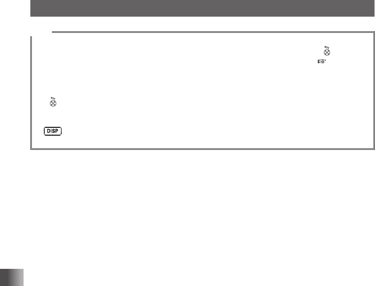
Transmitting/Receiving Signals
1 While pressing and holding , speak into the microphone�
Keep your mouth about 5 cm away from the microphone when you speak�
2 Release �
The transceiver returns to Reception mode�
Cautions
yUse the transceiver at the minimum required transmission power level� Doing so prevents the
transceiver from overheating and saves battery power, increasing the operating time�
yDo not continue transmitting for a prolonged period� The transceiver can overheat, resulting in
malfunction or burn�
yIf transmission is continued for a long period, the transceiver overheats and the overheat protection
function is activated� As a result, the transmitting power level is automatically set to Low Power� If
you continue transmitting while the overheat protection function is active, the transceiver will be
forcibly returned to the Reception mode�
yIf you touch the transceiver immediately after the overheat protection function has become active,
you can get burned� Wait for the temperature inside the transceiver to drop sufficiently before
resuming transmission�
yDo not perform transmission without attaching the antenna� The transmitter circuit can be damaged�
Application for FCC / IC
FCC ID: K6620605X20
IC: 511B-20605X20
36
Basic Operation
Performing Communication
Tips
• In FM mode, you can transmit on the 144 MHz and 430 MHz ham radio bands�
• Even while you are receiving in AM mode, you can transmit in NFM mode by pressing �
• You can change the transmit power level by touching [F MW] followed by [TXPWR] ( see page
xx)�
Transmit power level is different when using the battery pack or the alkaline battery case�
For more details, see “Changing the Transmission Power Level” on page xx�
• If is pressed when a frequency other than the amateur ham radio band is selected, an alarm tone
(beep) will be emitted and “ERROR” appears on the LCD, disabling transmission�
• You can select whether or not to prohibit transmission while receiving a signal� Press and hold
for over 1 second to switch the transceiver to Set mode, then with the setting from [CONFIG]
→ [2 BCLO], select [ON]�
Application for FCC / IC
FCC ID: K6620605X20
IC: 511B-20605X20
37
Basic Operation
Miscellaneous Settings
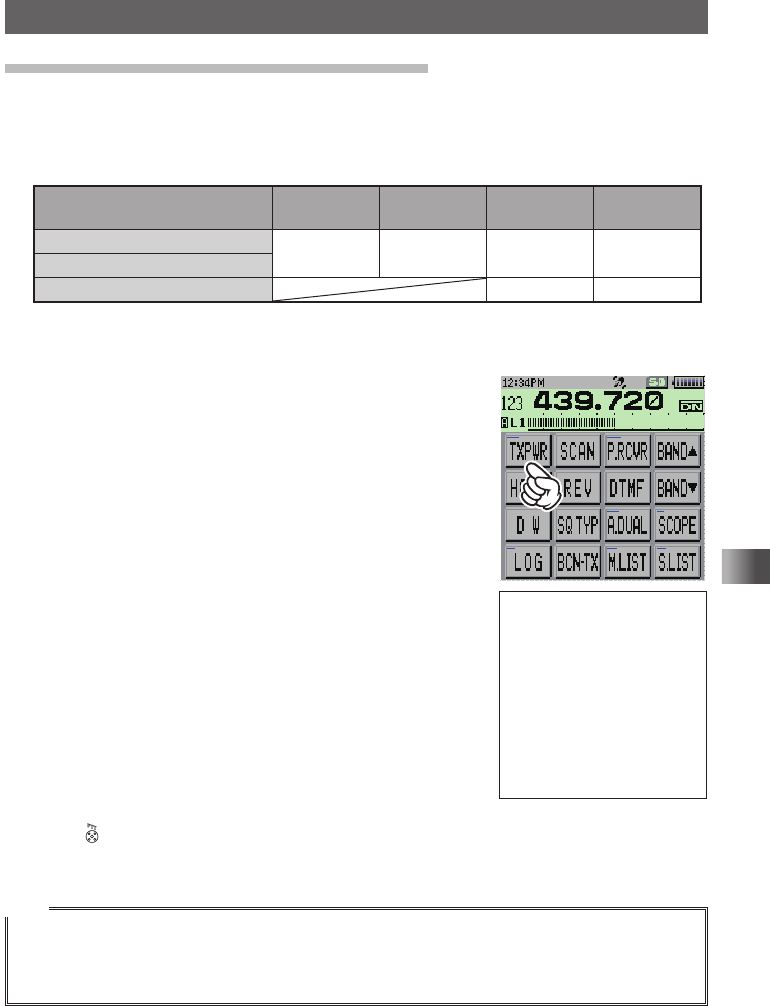
Changing the Transmission Power Level
The maximum transmission power level of this transceiver is 5 W� When communicating
with a friend in the immediate area or when you want to reduce the battery power
consumption, you can lower the transmit power level� For power supply types and
transmit power levels, see the table shown below�
Battery type
HI
(High Power)
L3 L2 L1
Battery pack 5W 2�5W 1W 0�1W
External power supply (DC13�8V)
Battery Case (alkaline battery) Approx� 0�8W 0�1W
1 Touch [F MW]�
2 Touch [TXPWR]�
MENU DISPLAY 2'!A7723 TOP画面プリセットレシーバー!A1
TOP画面AF-DUAL表示'!A1 Band Scope'!A1
FUNCTION!A389 APRS Message list1'!A1
APRS Station list1'!A1
3 Rotate the DIAL to select one of the following
transmission power levels�
“Hi”, “L1”, “L2”, “L3”
4 Press �
The transmission power level will be set�
Tips
• You can set the transmitter power level separately for the A-band and B-band�
• Use the transceiver at the minimum required transmit power level to reduce battery power
consumption�
• By default, “HI (High power)” is selected�
T�B�D�
Application for FCC / IC
FCC ID: K6620605X20
IC: 511B-20605X20
38
Basic Operation
Miscellaneous Settings
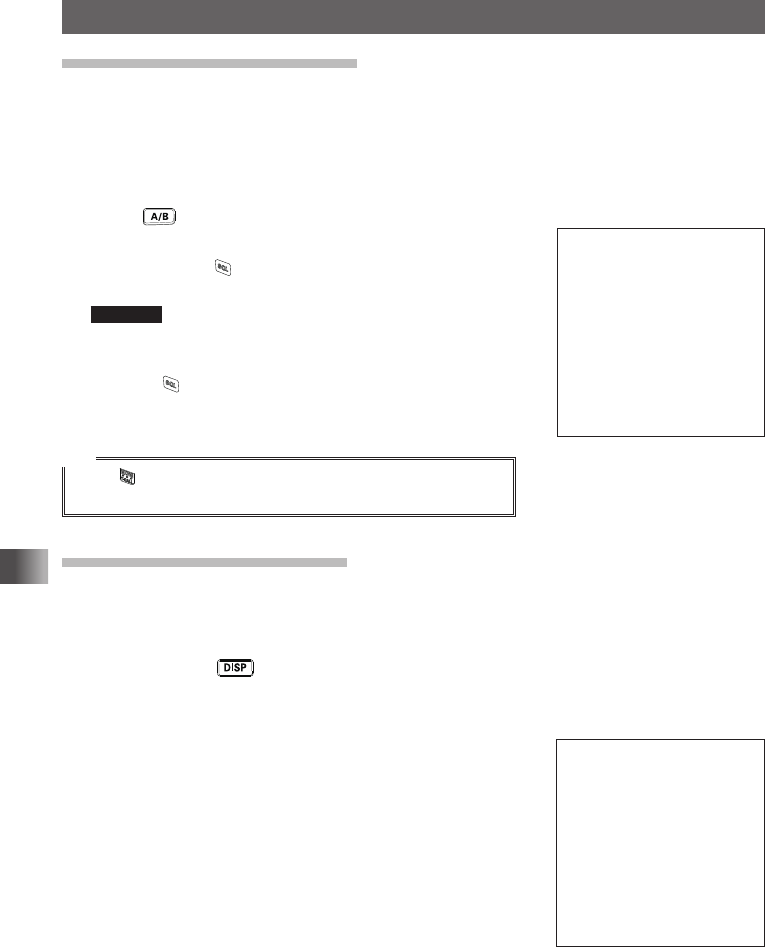
Adjusting the Squelch Level
You can mute the raspy noise heard when no signal is being received� The squelch level
can be adjusted separately for two broadcasts (FM and AM) received on the A-band and
B-band�
When the squelch level is increased, the noise is more liable to disappear, but it
becomes difficult to receive weak signals� Adjust the squelch level as required�
1 Press to set the band for which you want to adjust the squelch, to the operating
band�
2 While pressing , rotate the DIAL to adjust the squelch
level�
Remarks • The squelch level can be adjusted within the range
from 0 to 15�
• Default: LEVEL 1
3 Release �
The squelch level adjustment mode will be canceled�
Tip
While is held pressed, the squelch function will be
deactivated for both the A-band and B-band�
Setting the Frequency Step
By default, “AUTO (Step)” is selected so that the optimum frequency step is
automatically selected according to the received frequency� You can set the frequency
step to a fixed value�
1 Press and hold for over 1 second�
The transceiver enters Set mode�
2 Touch [CONFIG]�
3 Touch [18 STEP]�
T�B�D�
T�B�D�
Application for FCC / IC
FCC ID: K6620605X20
IC: 511B-20605X20
39
Basic Operation
Miscellaneous Settings
4 Rotate the DIAL to select your desired frequency step�
Remark Selectable frequency steps are as follows:
• AUTO • 5�0KHz • 6�25KHz
• (8�33KHz) • (9�0KHz) • 10KHz
• 12�5KHz • 15KHz • 20�0KHz
• 25�0KHz • 50�0KHz • 100�0KHz
It is recommended that AUTO be selected normally�
Default: AUTO
5 Press �
The frequency step setting mode will be canceled�
Tips
• For the AIR band (108 MHz to 136�991 MHz), the frequency step “8�33 kHz” can also be selected�
• For bands covering 250 MHz to 300 MHz, and bands covering 580 MHz or higher, the frequency
steps “5 kHz”, “6�25 kHz”, and “15 kHz” cannot be selected�
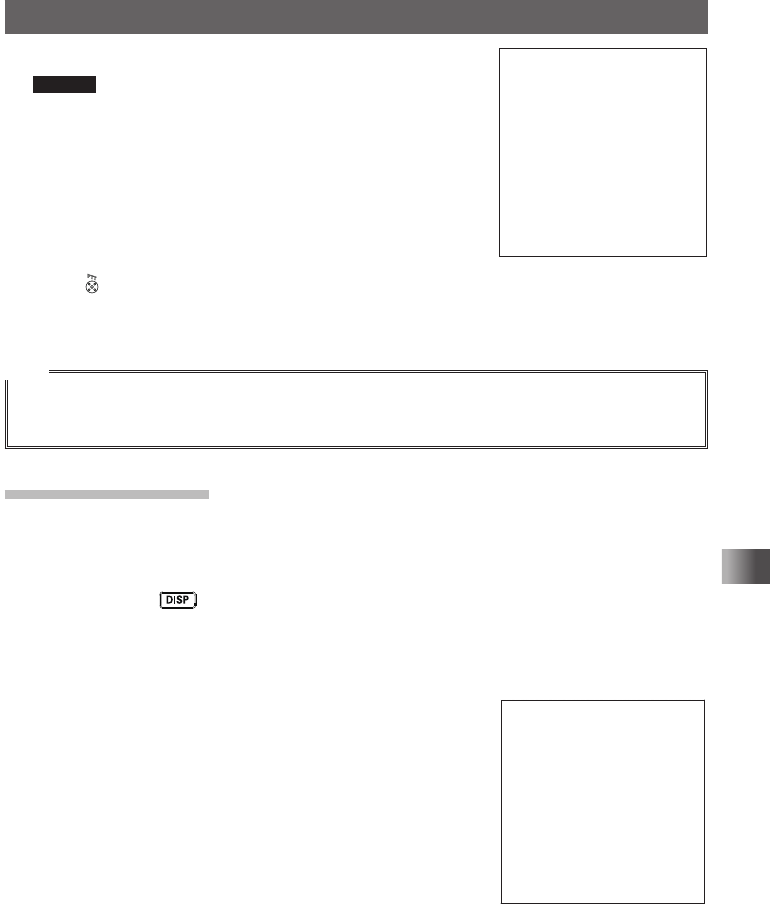
Changing the Mode
You can change the selected band mode�
By default, “AUTO (Auto Mode)” is set so that the optimal mode (radio wave type) is
automatically selected according to the band (frequency band)�
1 Press and hold for over 1 second�
The transceiver enters Set mode�
2 Touch [TX/RX]�
3 Touch [1 MODE]�
4 Touch [3 RX MODE]�
The current setting will be displayed�
T�B�D�
T�B�D�
Application for FCC / IC
FCC ID: K6620605X20
IC: 511B-20605X20
40
Basic Operation
Miscellaneous Settings
5 Rotate the DIAL to select your desired mode�
It is recommended that AUTO be selected normally�
Display Operation
AUTO The optimal mode is automatically selected according
to the frequency band�
NFM Only the selected band is switched to the NFM (FM
mode)�
AM Only the selected band is switched to the AM mode�
6 Press �
Set mode will be canceled�
Tip
Even if AM mode is selected on a ham radio band, 144 MHz band or 430 MHz band, transmission
takes place in the FM mode�
Caution
You cannot change the mode of A-band AM/FM broadcast radio bands�
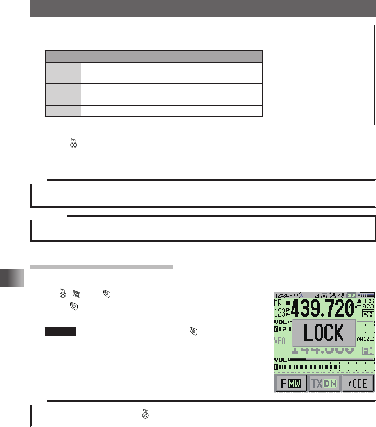
Locking Keys and Switches
To prevent accidental frequency change during operation, keys, switches and the DIAL
except , , and can be locked�
1 Press �
[LOCK] appears on the LCD�
Remark To unlock a key or switch, press again�
[UNLOCK] is displayed on the LCD for few seconds�
Tip
You can also lock the DIAL and by selecting the Set mode option [CONFIG] → [9 LOCK]�
T�B�D�
Application for FCC / IC
FCC ID: K6620605X20
IC: 511B-20605X20
41
Basic Operation
Miscellaneous Settings
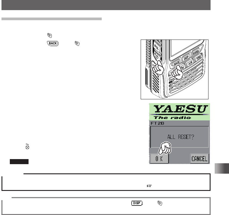
Restoring to Defaults (All Reset)
You can restore all transceiver settings and memory content to the defaults�
1 Press and hold for over 1 second, then turn off the transceiver�
2 While pressing press �
The transceiver turns on and you hear the beep�
3 When you hear the beep, release the key�
“ALL RESET?” appears on the LCD�
4 Touch [OK]�
A beep sounds and the call sign input screen appears
on the LCD�
5 Input the call sign�
Input the call sign using the numeric key pad�
6 Press �
The call sign is set and the frequency screen appears�
Remark To cancel resetting, touch [CANCEL]�
Caution
When the All Reset function is performed, all data registered in the memory will be deleted� Be sure to
write it down on paper or back up the data on a microSD memory card ( pages xx to xx)�
Tip
To restore only the Set Mode settings to default, while pressing , press to turn on the
transceiver�
Application for FCC / IC
FCC ID: K6620605X20
IC: 511B-20605X20
42
Using the Memory
Using the Memory
Registering to Memory Channel
Caution
The information registered to memory channels can be corrupted due to wrong operation, static
electricity, or electrical noise� Also, it can be erased in the case of a failure or repair� Be sure to write it
down on paper or back up the data on a microSD memory car ( see pages xx to xx)�
The transceiver allows you to use 900 memory channels (memory channel numbers 1
to 900)�
1 Press the key to enter VFO mode�
2 Rotate the DIAL to select the frequency you want
to register to a memory channel�
3 Touch [F MW] for over 1 second�
The transceiver enters Memory Channel
Registration mode, and the number of the memory
channel next to the most recently registered
memory will flash�
Remarks • To cancel the memory channel registration,
press �
• To specify a memory channel to which you want
to register the frequency, select the memory
channel by rotating the DIAL�
The ( icon indicating [The specified memory
channel is unregistered] lights up, and the
memory channel flashes�
The ) icon indicating [The specified memory
channel is registered] lights up�
• Pressing each time skips memory
channels quickly in steps of 100 memory
channels�
メモリー書き込み中!A1
Application for FCC / IC
FCC ID: K6620605X20
IC: 511B-20605X20
43
Using the Memory
A Wide Variety of Memory Functions
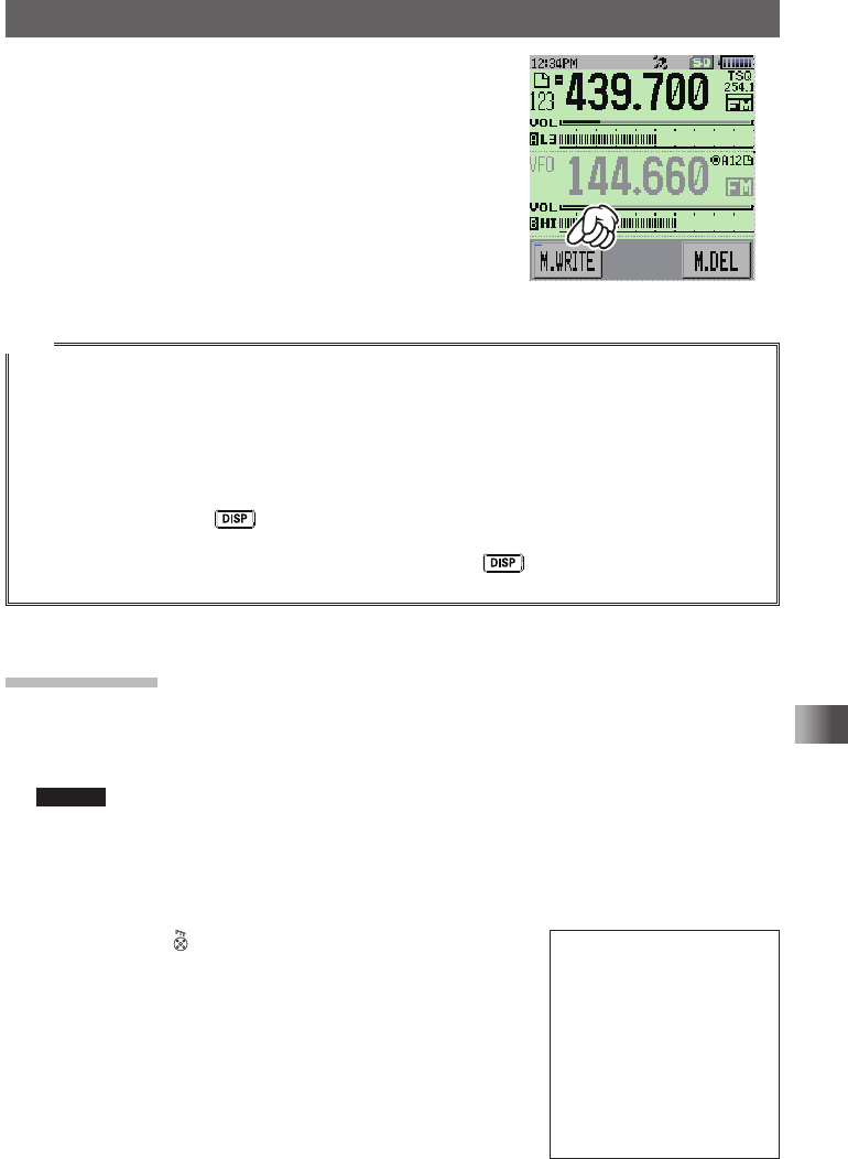
4 Touch [M.WRITE]�
The frequency registration will initiate�
If you attempt to register a frequency to a memory
channel on which another frequency has already
been registered, “Overwrite OK?” will appear on
the LCD�
Once the registration is completed, the frequency
will be displayed on the LCD�
TOP画面!A1
Tips
• By default, 145�000 MHz is registered to the memory channel 1� It can be changed to another
frequency, but not be deleted�
The frequency which has been registered to a memory channel can be overwritten with a new
frequency�
When you attempt to register a new frequency to a memory channel, an unregistered memory
channel appears�
• To display the lowest unregistered memory number when you register a frequency to a memory
channel, press and hold for over 1 second to enter Set mode, and then select [MEMORY] →
[6 MEMORY WRITE]�
• To inhibit registration to all memory channels, press and hold for over 1 second to enter Set
mode, and then select [MEMORY] → [4 MEMORY PROTECT]�
Split Memory
Two different frequencies, one for reception and other for transmission, can be
registered to a memory channel�
1 Register a reception frequency to a memory channel�
Remark See “Registering to Memory Channel” above�
2 Select a transmission frequency in VFO mode�
3 Touch [F MW] for over 1 second�
4 Rotate the DIAL to select the channel number to which you have registered the
reception frequency�
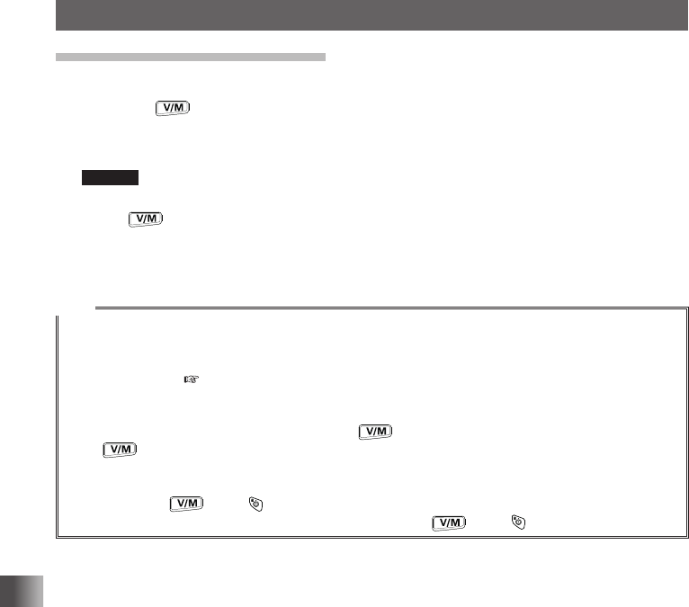
5 While pressing , touch [M.WRITE]�
When you recall the memory channel to which you
registered two different frequencies (one for receive and
the other for transmit), @ appears on the LCD� T�B�D�
Application for FCC / IC
FCC ID: K6620605X20
IC: 511B-20605X20
44
Using the Memory
A Wide Variety of Memory Functions
Recalling a Memory Channel
Recall a registered memory channel following the steps below�
1 Press the key to enter Memory mode�
The memory channel most recently used appears on the LCD�
2 Rotate the DIAL to select the desired memory channel�
Remark Touching [F MW] and rotating the DIAL allows you to skip memory channels quickly in
steps of 10 memory channels�
3 Press �
Memory mode will be canceled and the frequency selected in VFO mode will be
displayed�
Tips
• Unregistered memory channels are skipped�
• By default, a priority memory channel, which is used as dual receive priority memory channel, is
set to the memory channel number 1� “P” appears on the upper right corner of the priority memory
channel number ( see page xx)�
• The information registered to a memory channel can be transferred to the VFO operating band by
following procedure below�
Touch [F MW] for over 1 second. → Press the key. → “OVERWRITE OK?” appears. → Press
the key�
• Placing the transceiver in the Memory Channel Only mode by following the procedure below
restricts use to memory channels�
while pressing , press to turn on the transceiver�
To cancel the Memory Channel Only mode, while pressing , press again�
Application for FCC / IC
FCC ID: K6620605X20
IC: 511B-20605X20

45
Appendix
Appendix
Specifications
yGeneral
Frequency Range (A): RX: 0�5 - 1�8 MHz, 1�8 - 30 MHz,
30 - 76 MHz, 76 - 108 MHz,
108 - 137 MHz, 137 - 174 MHz,
174 - 222 MHz, 222 - 225 MHz,
222 - 420 MHz, 420 - 470 MHz,
470 - 800 MHz,
800 - 999 MHz (Cellular Blocked)
Frequency Range (B): RX: 108 - 137 MHz, 137 - 174 MHz,
174 - 222 MHz, 222 - 225 MHz,
222 - 420 MHz, 420 - 470 MHz,
470 - 580 MHz
Frequency Range (A/B): TX: 144 - 148 MHz,
430 - 450 MHz
Channel Steps: 5, 8�33, 9, 10, 12�5, 15, 20, 25, 50, 100 kHz
Mode of Emission: F1D, F2D, F3E, F7W
Antenna Impedance: 50 Ω, unbalanced
Frequency Stability: ±2.5 ppm (−10 °C to +50 °C)
Operating Temperature Range: −20 °C to +60 °C
Supply Voltage: 7�4 V DC (Rated),
4 - 9 V DC (Battery terminal Input),
10 - 16 V DC (EXT DC Input)
Current Consumption (Approx.): RX: 250 mA (Analog / Mono Band)
300 mA (Digital / Mono Band)
TX: 1�6 A (144 MHz / Analog)
1�7 A (144 MHz / Digital)
2�0 A (430 MHz / Analog)
2�1 A (430 MHz / Digital)
Case Size (W × H × D): 62 × 110 × 32�5 mm (w/o knobs & antenna)
Weight (Approx.): 310 g (with Battery & Antenna)
Application for FCC / IC
FCC ID: K6620605X20
IC: 511B-20605X20

46
Appendix
Specifications
yTransmitter
Output Power: 5 W (144 / 430 MHz), 2�5 W (144 / 430MHz)
1�0 W (144 / 430 MHz), 50 mW (144 / 430MHz)
Modulation Type: Variable Reactance
Maximum Deviation: ±5 kHz
Spurious Radiation: better than −60 dB
Microphone Impedance: 2 k ohm
yReceiver
Circuit Type: Double-conversion super heterodyne (N-FM / AM)
Intermediate Frequency: 1st: A- Band 47�25 MHz (N-FM / AM)
1st: B- Band 46�35 MHz (N-FM / AM)
2nd: 450 kHz (N-FM / AM)
Sensitivity (for 12dB SINAD): 0�5 - 1�8 MHz: 3�00
μ
V(S/N 10 dB)
1�8 - 30 MHz: 3�00
μ
V(S/N 10 dB)
30 - 50 MHz: 0�50
μ
V(12 dB SINAD)
50 - 54 MHz: 0�18
μ
V(12 dB SINAD)
54 - 76 MHz: 1�00
μ
V(12 dB SINAD)
76 - 108 MHz: 1�00
μ
V(12 dB SINAD)
108 - 137 MHz: 1�50
μ
V(S/N 10 dB)
137 - 174 MHz: 0�18
μ
V(12 dB SINAD)
174 - 225 MHz: 1�00
μ
V(12 dB SINAD)
222 - 225 MHz: 0�50
μ
V(12 dB SINAD)
300 - 350 MHz: 0�50
μ
V(12 dB SINAD)
350 - 420 MHz: 0�20
μ
V(12 dB SINAD)
420 - 470 MHz: 0�18
μ
V(12 dB SINAD)
470 - 580 MHz: 0�35
μ
V(12 dB SINAD)
580 - 800 MHz: 3�00
μ
V(12 dB SINAD)
800 - 999 MHz: 1�00
μ
V(12 dB SINAD)
(USA Version Cellular Blocked)
Selectivity (−6dB/−60dB): 15 kHz / 35 kHz (N-FM/AM)
Maximum AF Output: 200 mW @ 7�4V, 10% THD
AF Output Impedance: 8 ohm
Specifications are subject to change without notice, and are guaranteed within the 144/222 (USA
version)/430 MHz amateur bands only.
Application for FCC / IC
FCC ID: K6620605X20
IC: 511B-20605X20

47
Appendix
1� Changes or modifications to this device not expressly approved by YAESU
MUSEN could void the user’s authorization to operate this device�
2� This device complies with part 15 of the FCC Rules� Operation is subject to the
following two conditions: (1) This device may not cause harmful interference, and
(2) this device must accept any interference including received, interference that
may cause undesired operation�
3� The scanning receiver in this equipment is incapable of tuning, or readily being
altered, by the User to operate within the frequency bands allocated to the
Domestic public Cellular Telecommunications Service in Part 22�
This device complies with Industry Canada license-exempt RSS standard(s)�
Operation is subject to the following two conditions: (1) this device may not
cause interference, and (2) this device must accept any interference, including
interference that may cause undesired operation of the device�
Le présent appareil est conforme aux CNR d’Industrie Canada applicables aux
appareils radio exempts de licence� L’exploitation est autorisée aux deux conditions
suivantes : (1) l’appareil ne doit pas produire de brouillage, et (2) l'utilisateur de
l’appareil doit accepter tout brouillage radioélectrique subi, même si le brouillage
est susceptible d’en compromettre le fonctionnement�
Part 15�21: Changes or modifications to this device not expressly approved by
YAESU MUSEN could void the user’s authorization to operate this device�
DECLARATION BY MANUFACTURER
The Scanner receiver is not a digital scanner and is incapable of being converted or
modified to a digital scanner receiver by any user�
WARNING: MODIFICATION OF THIS DEVICE TO RECEIVE CELLULAR
RADIOTELEPHONE SERVICE SIGNALS IS PROHIBITED UNDER FCC RULES
AND FEDERAL LAW�
Application for FCC / IC
FCC ID: K6620605X20
IC: 511B-20605X20

YAESU MUSEN CO., LTD.
Tennozu Parkside Building
2-5-8 Higashi-Shinagawa, Shinagawa-ku, Tokyo
140-0002 Japan
YAESU USA
6125 Phyllis Drive, Cypress, CA 90630, U.S.A.
YAESU UK
Unit 12, Sun Valley Business Park, Winnall Close
Winchester, Hampshire, SO23 0LB, U.K.
Copyright 2015
YAESU MUSEN CO., LTD.
All rights reserved.
No portion of this manual
may be reproduced
without the permission of
YAESU MUSEN CO., LTD.
Printed in Japan
1409P-AO
Application for FCC / IC
FCC ID: K6620605X20
IC: 511B-20605X20