Yaesu Musen 20663X20 AMATEUR HANDHELD VHF RADIO - SCANNING RECEIVER User Manual OM
Yaesu Musen Co., Ltd. AMATEUR HANDHELD VHF RADIO - SCANNING RECEIVER OM
Contents
- 1. User Manual 1
- 2. User Manual 2
- 3. User Manual 3
User Manual 2
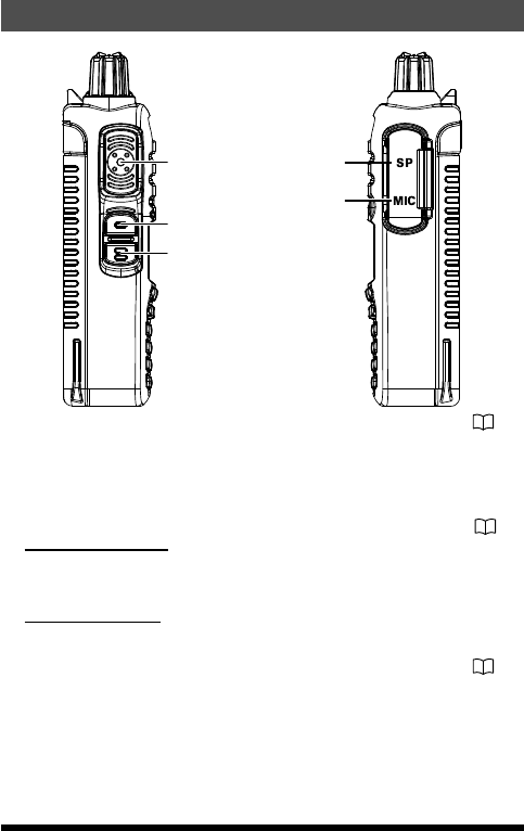
Controls & Connections (Side Panel)
PTT (Push To Talk) Switch .................................................. 21
• Press this switch to transmit, and release it (to receive) after your trans-
mission is completed.
• In the Set mode, press the PTT switch to save the new setting and return
to normal operation.
MONI/T.CALL Key (Function is selectable from Set mode)
..................................................................................................... 28
•USA/Asian Version:
Press this switch to open the squelch, and listen for very weak signals
near the background noise level.
•European Version:
Pressing this switch activates the T-CALL (1750 Hz) for repeater access.
F key ..................................................................................... 22
Press and hold this key to enter the Set Mode.
SP Jack
This three-conductor miniature jack provides connection for an external
speaker.
MIC Jack
This three-conductor miniature jack provides connections for microphone
audio, earphone audio, PTT, and ground.
11FT-25R/FT-25E Operating Manual
Application for FCC / IC
FCC ID: K6620663X20, IC: 511B-20663X20
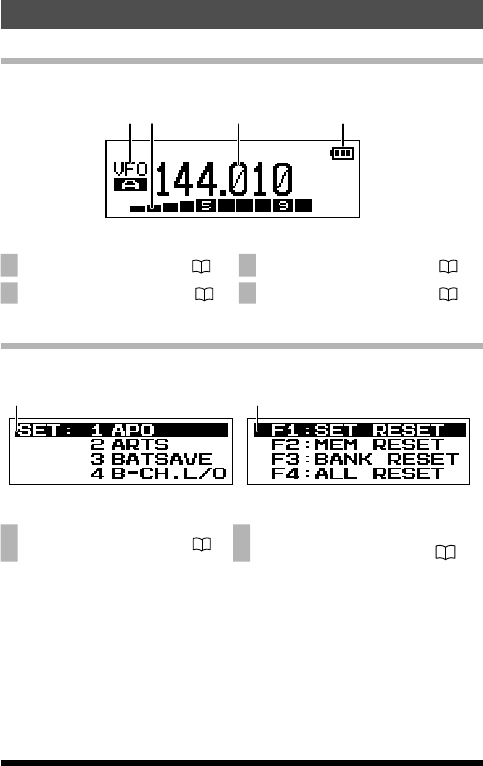
Controls & Connections (LCD)
Normal operation display
2 3 41
1 VFO-A / VFO-B .................. 23 3 Operating Frequency ........ 20
2 S & PO Meter ..................... 21 4 Battery Indicator ………… 18
The Set Mode and Preference Mode display
Set Mode Preferred Operating Mode
56
5 Set Mode Menu ................. 22 6 Preferred Operating Mode ............
............................................. 23
12 FT-25R/FT-25E Operating Manual
Application for FCC / IC
FCC ID: K6620663X20, IC: 511B-20663X20
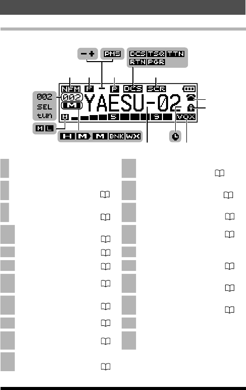
Display of features and settings
7 8 11
9 10 12
13
14
15
16
24
2122 20
27
26
25
v
v
v v
19 18 17
v
23
7Operating Mode 18 Memory Tag Name .....................
....................................... 30,31
8Secondary Keypad Active ..........
............................................. 14 19 Weather Channel* ......................
........................................... 34
9Repeater Shift Direction..............
............................................. 27 20 Memory Bank ............................
............................................ 29
10 Programmable Memory (Mode
(VFO)) Scan ..................... 36 21 Memory Mode ................... 29
11 Priority Channel .............. 14 22 Skipped Memory Channel
12 Squelch Operation .......... 39 23 Home Channel .................. 32
13 Scramble Feature* .......... 39 24 TX Power Level Indicator .........
............................................ 21
14 DTMF Mode ..................... 39 25 Memory Offset Tuning ...............
............................................ 32
15 Keypad Lock .................. 24 26 Selecting ICON indicator
16 VOX Feature .................... 39 27 Memory (BANK) Channel Num-
ber
17 Automatic Power-Off Feature ..
.......................................... 39
* This feature is displayed depending on the transceiver version.
13
Control & Connections (LCD)
FT-25R/FT-25E Operating Manual
Application for FCC / IC
FCC ID: K6620663X20, IC: 511B-20663X20
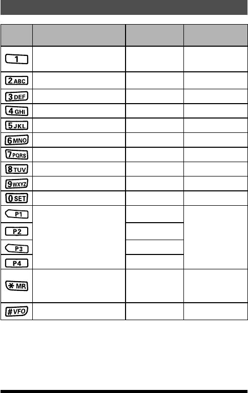
Controls & Connections (Keypad)
Key Primary Function
(PRESS Key)
Secondary Func-
tion
(PRESS F + Key)
Third Function
(Press and Hold Key)
Frequency entry digit “1” ―
Recalls the “Weather”
broadcast
channel bank
Frequency entry digit “2” ―Activates the ARTS
feature
Frequency entry digit “3” ― ―
Frequency entry digit “4” ― ―
Frequency entry digit “5” ― ―
Frequency entry digit “6” ―Key Lock feature
Frequency entry digit “7” ― ―
Frequency entry digit “8” ― ―
Frequency entry digit “9” ― ―
Frequency entry digit “0” ― ―*1
recalls the stored or
assigned setting
HOME (Fixed
setting)
store or assign a
setting to the key
TX PWR (Fixed
setting)
FM radio
REV (Fixed setting)
recalls the Memory Mode and
activates the “Memory “Tune”
Mode while in the Memory
Mode.
Activates the Priori-
ty function Memory write mode
Switches VFO-A and VFO-B
PMS(Program Mem-
ory (Mode) Scan)
Program Scan Setting
*1 : When entering a frequency from the keypad, there is a short-cut for
frequencies ending in zero - after the last non-zero digit, press and hold
the [0/SET] key to enter all the zeros at once.
14 FT-25R/FT-25E Operating Manual
Application for FCC / IC
FCC ID: K6620663X20, IC: 511B-20663X20
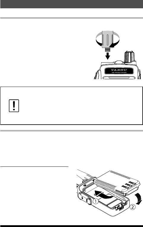
Installation of Accessories
Antenna Installation
The supplied antenna provides good results over the entire frequency range
of the transceiver. However, for enhanced reception on certain non-Amateur
frequencies, you may wish to connect an an-
tenna designed specically for that frequency
range, as the supplied antenna is necessarily
a compromise outside the Amateur bands,
and cannot be expected to provide high per-
formance at all frequencies.
To install the supplied antenna, hold the bot-
tom end of the antenna, then screw it onto the
mating connector on the transceiver until it is
snug. Do not over-tighten by using of extreme
force.
• Never transmit without having an antenna connected.
• When installing the supplied antenna, never hold the upper
part of the antenna while screwing it onto the mating con-
nector on the transceiver.
• If using an external antenna for transmission, ensure that the
SWR presented to the transceiver is 1.5:1 or lower, to avoid
excessive feedline loss.
Preparation of SBR-25LI Battery Pack
The SBR-25LI is a high-performance Li-Ion battery providing long operating
time in a compact package. Under normal use, the SBR-25LI may be used
for approximately 300 charge cycles, after which operating time may be ex-
pected to decrease. When an old battery pack exhibits diminished capacity,
replace the pack with a new one.
Installing the Battery Pack
1. Insert the battery pack into the bat-
tery compartment on the back of the
transceiver(
).
2. Push the battery in until the battery
latch on the lower back side of the
transceiver clicks securely().
15FT-25R/FT-25E Operating Manual
Application for FCC / IC
FCC ID: K6620663X20, IC: 511B-20663X20
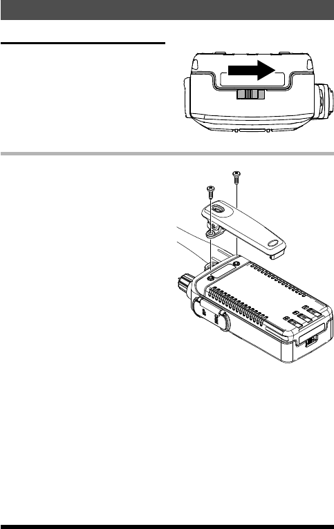
Removing the Battery Pack
To remove the battery, turn the
transceiver OFF. While sliding the latch
in the direction of the arrow, as shown
in the illustration, slide the battery pack
downward and out of the transceiver.
Attaching the Belt Clip
Attach the belt clip on the back of
transceiver using the supplied screws
(two).
16
Installation of Accessories
FT-25R/FT-25E Operating Manual
Application for FCC / IC
FCC ID: K6620663X20, IC: 511B-20663X20
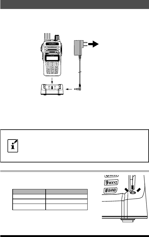
Charging the Battery Pack
If the battery has never been used, or its charge is depleted, it may be
charged by placing the FT-25R/E in the SBH-22 Rapid Charger desktop cra-
dle, connected with the SAD-20B/C/U/G AC adapter.
DC jack
AC line outlet
A fully-discharged SBR-25LI Battery Pack will be charged completely in
about 2.5 hours (depending on the battery being charged). Disconnect the
SAD-20B/C/U/G from the DC jack and the AC line outlet.
• The SAD-20B/C/U/G is not designed to power the trans-
ceiver for operation (reception or transmission).
• Please be advised that the SAD-20B/C/U/G may contribute
noise to TV and radio reception in the immediate vicinity, so
we do not recommend its use adjacent to such devices.
About Desktop charger lamp
The battery charging status is indicated by the
desktop charger lamp, as shown in the below table:
Lamp Status Description
Red lighting Charging
Green lighting Charge Complete
Red blinking Charge Error
FT-25R/E / SBH-22 with SAD-20B
(Example of USA model)
17FT-25R/FT-25E Operating Manual
Application for FCC / IC
FCC ID: K6620663X20, IC: 511B-20663X20
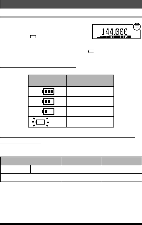
Low Battery Indication
• As the battery discharges during use, the
voltage will gradually become lower. When
the battery voltage is too low for reliable op-
eration, the “ ” icon will blink on the LCD
display, indicating that the battery pack must
be recharged before further use.
• Avoid recharging Li-Ion batteries before the “ ” indicator is observed, as
this can degrade the charge capacity of your Li-Ion battery pack.
About Battery Indicator Icons
Battery charge indicator icons are shown below:
Icons Description
Full battery power
Enough battery power
Low battery power
(w/blink) charge (or replace) the
battery
Approximate Operating Time and Remaining Charge
Level Indication
Approximate operating time for the transceiver with the fully charged battery
pack is as follows.
Frequency Band SBR-25LI SBR-26LI
Amateur Band 144 MHz band Approx. 10.0 hours Approx. 12.5 hours
FM Broadcast Band Approx. 11.0 hours Approx. 15.0 hours
Transmit 6 seconds; Receive 6 seconds; Stand by 48 seconds.
18
Charging the Battery Pack
FT-25R/FT-25E Operating Manual
Application for FCC / IC
FCC ID: K6620663X20, IC: 511B-20663X20
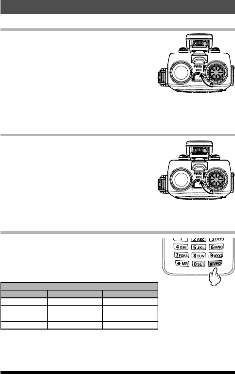
Basic Operation
Turn the Power ON and OFF
• Be sure the Battery Pack is installed, and is fully
charged. Connect the antenna to the top panel
Antenna jack.
• Rotate the PWR/VOL knob out of the click-
stop to turn the transceiver ON. The current DC
supply voltage will be shown on the display for
two seconds. After the two second interval, the
display will commence the normal operating fre-
quency indication.
• To turn the transceiver OFF, turn the PWR/VOL knob fully counter-clock-
wise into the click-stop position.
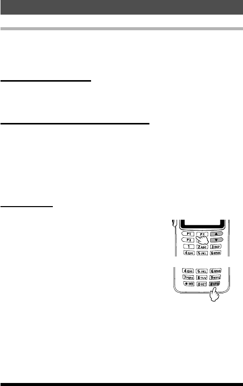
Adjust the Audio Volume Level and Squelch Setting
Rotate the PWR/VOL knob to adjust the receiver
volume. Listen to the open squelch background
noise to adjust the audio to a comfortable level.
1. To set the squelch level, press the F key and
then press the MONI/T.CALL key, to open the
SQ LEVEL set mode.
2. Press the [] or [] key to adjust to a level at
which the background noise is muted.
3. Press the PTT switch to save the squelch setting and return to normal
operation.
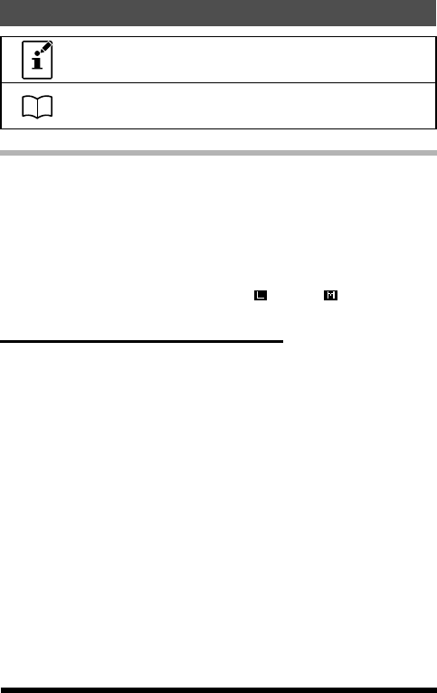
Changing between VFO-A and VFO-B
• Press the [#VFO] key repeatedly to toggle the
frequency control between the VFO mode and
the Memory mode.
• Frequency ranges are shown in the table.
Frequency Range
RX TX
USA model 137-174 MHz 144-148 MHz
European
model 137-174 MHz 144-146 MHz
Asian model 137-174 MHz 136-174 MHz
19FT-25R/FT-25E Operating Manual
Application for FCC / IC
FCC ID: K6620663X20, IC: 511B-20663X20
Frequency Navigation
The FT-25R/E will initially be operating in the “VFO” mode. The VFO permits
free tuning throughout the currently-selected operating band in designated
frequency steps (operating channels).
Three basic frequency navigation methods are provided on the FT-25R/E:
1) Tuning Frequency
Pressing the [] key tunes the FT-25R/E toward a higher frequency, while
pressing the [] key will lower the operating frequency, in steps prepro-
grammed for the current operating band.
2) Direct Keypad Frequency Entry
The operating frequency may be entered directly from the keypad by press-
ing the numbered digits on the keypad in the proper sequence.
Examples:
To enter 145.560 MHz, press [1] [4] [5] [5] [6] [0]
To enter 145.000 MHz*, press [1] [4] [5] [0] [0] [0]
*There is a short-cut to enter frequencies ending in zeros - after
the last non-zero digit, press and hold the [0/SET] key to enter the
remaining zeros.
3) Scanning
Manual VFO Scan:
To manually initiate VFO scanning, press and
hold either the [] or [] key to begin upward or
downward scanning, respectively.
Programmed Mode VFO Scan:
To begin scanning within a limited sub-band
range from the VFO mode, press and hold the
[#VFO] key to select the bandwidth for the Pro-
grammed Mode (VFO) scanner. Then press the F
key and the [#VFO] key to start scanning.
The scanner will stop when it receives a signal
strong enough to open the Squelch threshold.
(Manual VFO Scan)
(Programmed Mode
VFO Scan)
The FT-25R/E will then hold on that frequency in accordance with the “RE-
SUME” mode setting (Set Mode Item “25 RESUME”).
Press the PTT switch momentarily to cancel the scanning (this only stops the
scan; it does not cause a transmission to occur).
20
Basic Operation
FT-25R/FT-25E Operating Manual
Application for FCC / IC
FCC ID: K6620663X20, IC: 511B-20663X20
The direction of the scan may not reverse while FT-25R/E is
scanning.
For more details on the scanning, see page 35.
Transmission
• To transmit, press the PTT switch, and speak into the front panel micro-
phone (located in the lower left-hand corner of the speaker grille) in a nor-
mal voice level. The TX/BUSY indicator will glow red during transmission.
• To return to the receive mode, release the PTT switch.
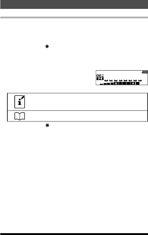
• During transmit, the power level will be indicated relatively on the bar
graph at the bottom of the LCD. Full scale deection conrms “High Pow-
er” operation. Five bars indicate “Medium Power” operation, while one bar
indicates “Low Power” operation. Additionally, while operating on the “Low
Power” or “Medium Power” setting, the “ ” icon or “ ” icon will appear
at the bottom-left of the display.
Changing the Transmit Power Level
To change the power level:
1. Press the F key and then press the [P2] key.
• The present TX power output level will appear on the display.
• To adjust the TX power in the Set Mode, press and hold the F key.
Then repeatedly press the [▲] or [▼] key to select Set Mode item “32 TX
PWR” and then press the F key.
2. Press the [▲] or [▼] key to select the desired power output level.
Available selections are “HI ” (5 W), “MID” (2.5 W), and “LOW” (0.5 W).
3. Press the PTT switch to save the new setting and return to normal oper-
ation.
21
Basic Operation
FT-25R/FT-25E Operating Manual
Application for FCC / IC
FCC ID: K6620663X20, IC: 511B-20663X20
Activating the Set Mode
Use the following procedure to activate the Set Mode and configure the
transceiver parameters.
1. Press and hold the F key to enter the Set Mode.
2. Repeatedly press the [▲] or [▼] key to select the Set Mode Item to be
adjusted.
3. Press the F key momentarily to enable adjustment of the Set Mode Item.
4. Press the [▲] or [▼] key to adjust the level, or choose the parameter, of the
selected Set Mode Item.
5. After completing the selection and adjustment, press the PTT switch to
save the new setting and exit to normal operation.
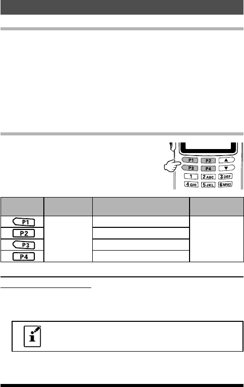
Setting the Quick Recall Keys
The four keys (P1, P2, P3 & P4), are user pro-
grammable. The four keys are assigned as shown
in the table:
Quick
Recall Key Press Press after pressing F key Press and hold
recall the
stored or
assigned
setting
HOME (Fixed setting)
store or assign
a setting to the
key
TX PWR (Fixed setting)
SQL TYPE (Fixed setting)
REV (Fixed setting)
Assigning Set Mode Items to the Quick Recall Keys (Set
Mode Recall feature)
1. Press and hold the F key to enter the Set Mode.
2. Press the [▲] or [▼] key to select the Set Mode Item to be assigned to the
quick recall key as a recalled Menu item.
The quick recall keys can store and recall favorite frequen-
cy settings, and are also short-cut keys to the Set Mode
menu items.
3. Press and hold the [P1], [P2], [P3] or [P4] key to assign the Set Mode Item
to the quick recall key.
4. Press the [P1], [P2], [P3] or [P4] key to recall the assigned Set Mode Item.
22
Basic Operation
FT-25R/FT-25E Operating Manual
Application for FCC / IC
FCC ID: K6620663X20, IC: 511B-20663X20
Storing the displayed Frequency and Settings to a
Quick Recall Key (Quick Memory feature)
1. While operating in the VFO mode or the Memory mode, set the desired
frequency and associated settings.
2. Press and hold the [P1], [P2], [P3] or [P4] key to store the frequency and
settings to a Programmable key.
3. Press the [P1], [P2], [P3] or [P4] key to recall the stored settings.
A Quick recall key may also store the frequency and asso-
ciated settings in the Memory Mode.
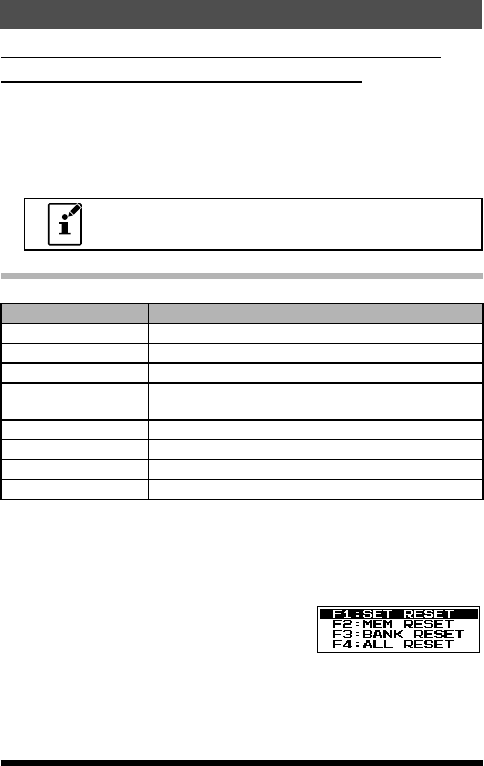
Setting the Preferred Operating Mode
The following reset or preferred operating modes may be selected.
Display Description
F1:SET RESET Reset the Set Mode settings to factory defaults.
F2:MEM RESET Clear the Memory settings to factory defaults.
F3:BANK RESET Clear the Memory Bank assignments.
F4:ALL RESET Clear the All memories and other settings to factory
defaults.
F5:MEM-ONLY Operation on the Memory mode only.
F6:VHF-ONLY Operation on the VHF Band only.
F7:FM-ONLY Operation on the FM Band only.
F8 CLONE Clone mode.
1. Turn the transceiver OFF.
2. Press and hold the MONI/T.CALL key and the PTT switch simultaneously,
while turning the radio ON.
3. When the LCD backlight comes on, release the MONI/T.CALL key and
PTT switch.
4. Referring to the above table, press the [▲] or
[▼] key to select the desired operating mode.
5. Press the F key momentarily to activate the selected operating mode.
23
Basic Operation
FT-25R/FT-25E Operating Manual
Application for FCC / IC
FCC ID: K6620663X20, IC: 511B-20663X20
Advanced Operation
After becoming familiar with the basic operations of the FT-25R/E, you will
want to learn about some of the really handy operating and convenience fea-
tures.
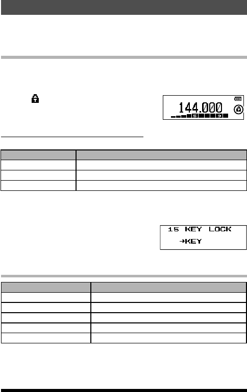
Turning the Keylock Feature ON and OFF
The FT-25R/E keypad may be locked to prevent accidental frequency
change or inadvertent transmissions,
1. Press and hold the [6] key to lock the keys and switches.
•The icon will appear on the LCD display.
•To unlock, press and hold the [6] key again.
Change the key locking scheme
The following locking schemes may be selected.
Display Description
KEY(default setting) Just the front panel keypad is locked out.
PTT The PTT switch is locked out (TX not possible).
P+K Both the PTT switch and the keypad are locked out.
1. Press and hold the F key to enter the Set Mode.
2. Press the [▲] or [▼] key to select Set Mode Item “15 KEY LOCK”.
3. Press the F key momentarily to enable adjustment of this Item.
4. Press the [▲] or [▼] key to choose one of the
above listed locking schemes.
5. Press the PTT switch to save the new setting and return to normal oper-
ation.
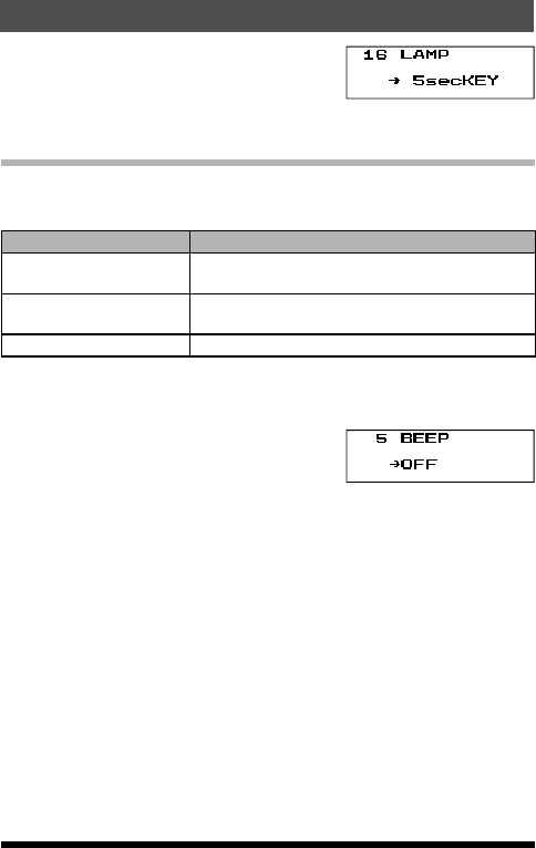
Change the LCD and keypad back light setting
Display Description
5secKEY (default setting) Keypad and LCD Lamp lights for 5sec.
10secKEY Keypad and LCD Lamp lights for 10sec.
30secKEY Keypad and LCD Lamp lights for 30sec.
CONT Keypad and LCD Lamp lights continually.
OFF Disable the Keypad and LCD Lamp function.
1. Press and hold the F key to enter the Set Mode.
2. Press the [▲] or [▼] key to select Set Mode item “16 LAMP”
3. Press the F key to enable adjustment of this Item.
24 FT-25R/FT-25E Operating Manual
Application for FCC / IC
FCC ID: K6620663X20, IC: 511B-20663X20
4. Press the [▲] or [▼] key to select one of the
modes described above.
5. Press the PTT switch to save the new setting and return to normal oper-
ation.
Disabling the Keypad and Scan Stop Beeper
An audible beep tone will sound when a keypad button is pressed, and also
when the receiver scanning stops. The beep tone operation may be changed
as shown in the below table:
Display Description
KEY The beeper sounds when a keypad button is
pressed.
KEY+SC(default setting) The beeper sounds when a keypad button is
pressed, or when the receiver scanning stops.
OFF The beeper does not sound.
1. Press and hold the F key to enter the Set Mode.
2. Press the [▲] or [▼] key to select Set Mode item “5 BEEP”
3. Press the F key to enable adjustment of this Item.
4. Press the [▲] or [▼] key to select “OFF”
5. Press the [▲] or [▼] key to select one of the
modes described above.
6. Press the PTT switch to save the new setting and return to normal oper-
ation.
7. To turn the beep back on again, select “KEY” or “KEY+SC (Default setting)”
in step 4 above.
25
Advanced Operation
FT-25R/FT-25E Operating Manual
Application for FCC / IC
FCC ID: K6620663X20, IC: 511B-20663X20
Repeater Operation
Repeater stations are often located on mountaintops or other high locations,
and provide a dramatic extension of the communication range for low-pow-
ered hand-held or mobile transceivers. The FT-25R/E includes a number of
features which make repeater operation simple and enjoyable.
Repeater Shifts
The transceiver has been congured at the factory for the repeater shifts
customary in the sales destination country. For the 144 MHz band the re-
peater shift will be 0.6 MHz.
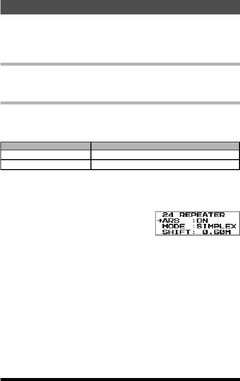
Automatic Repeater Shift (ARS)
The FT-25R/E provides a convenient Automatic Repeater Shift feature, which
automatically applies the appropriate repeater frequency shift when tuning in
the repeater sub-bands of the designated country. The ARS setting options
are listed below:
Display Description
ARS : ON (default setting) Enable the Automatic Repeater Shift function.
ARS : OFF Disable the Automatic Repeater Shift function.
1. Press and hold the F key to enter the Set Mode.
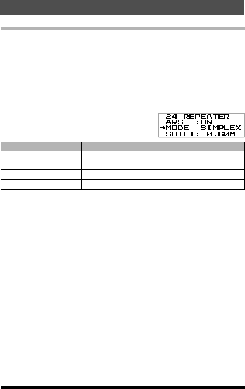
2. Press the [▲] or [▼] key to select Set Mode item “24 REPEATER”
3. Press the F key to enable adjustment of this Item.
4. Press the F key to enable ARS.
5. Press the [▲] or [▼] key to select “ON” or
“OFF”.
6. Press the PTT switch to save the new setting
and return to normal operation.
26 FT-25R/FT-25E Operating Manual
Application for FCC / IC
FCC ID: K6620663X20, IC: 511B-20663X20
Manual Repeater Shift Setting
If the ARS feature has been deactivated, or if a repeater shift direction other
than the established ARS setting is desired, the repeater shift direction may
be set manually.
1. Press and hold the F key to enter the Set Mode.
2. Press the [▲] or [▼] key to select Set Mode item “24 REPEATER”, then
press the F key to enable this item.
3. Press the [▲] or [▼] key to select MODE, and press F key to enable this
item.
4. Press the [▲] or [▼] key to select the Shift
Mode, and press the F key to enable adjust-
ment of this Item.
Display Description
MODE : SIMPLEX
(default setting) Disable the Manual Repeater Shift function.
MODE : +REP Enable the Manual Repeater Shift + direction.
MODE : -REP Enable the Manual Repeater Shift - direction.
5. To change the repeater shift magnitude, press the [▲] or [▼] key to select
SHIFT.
6. Press the F key to enable adjustment of this Item.
7. Press the [▲] or [▼] key to select the repeater shift magnitude (0.05 MHz
~ 99.95 MHz).
8. Press the PTT switch to save the new setting and return to normal oper-
ation.
27
Repeater Operation
FT-25R/FT-25E Operating Manual
Application for FCC / IC
FCC ID: K6620663X20, IC: 511B-20663X20
Tone Calling (1750 HZ)
For operation in counties that require a 1750-Hz burst tone for repeater
access (typically in Europe), the MONI/T.CALL key may be programmed to
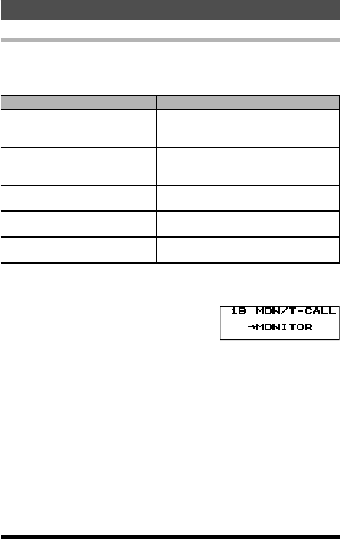
serve as a “Tone Call” key instead. Use Set Mode item “19 MON/T-CL”, to
change the conguration of this key.
Display Description
MONITOR
(default setting (USA and Asian
version))
Pressing the MONI/T.CALL key opens
the receiver noise squelch.
T-CALL1750
(default setting (European ver-
sion))
Pressing the MONI/T.CALL key acti-
vates the 1750 Hz burst tone.
T-CALL2100 Pressing the MONI/T.CALL key acti-
vates the 2100 Hz burst tone.
T-CALL1000 Pressing the MONI/T.CALL key acti-
vates the 1000 Hz burst tone.
T-CALL1450 Pressing the MONI/T.CALL key acti-
vates the 1450 Hz burst tone.
1. Press and hold the F key to enter the Set mode.
2. Press the [▲] or [▼] key to select Set Mode item “19 MON/T-CL”.
3. Press the F key to enable adjustment of this Item.
4. Press the [▲] or [▼] key to select a Tone
Calling feature.
5. Press the PTT switch to save the new setting
and return to normal operation.
To access a tone burst controlled repeater, press and hold in the MONI/
T.CALL key for the time duration specified by the repeater owner/operator.
The transmitter will automatically be activated, and the 1750-Hz audio tone
will be superimposed on the carrier. Once the repeater is accessed, release
the MONI/T.CALL key and use the PTT switch to activate the transmitter
thereafter.
28
Repeater Operation
FT-25R/FT-25E Operating Manual
Application for FCC / IC
FCC ID: K6620663X20, IC: 511B-20663X20
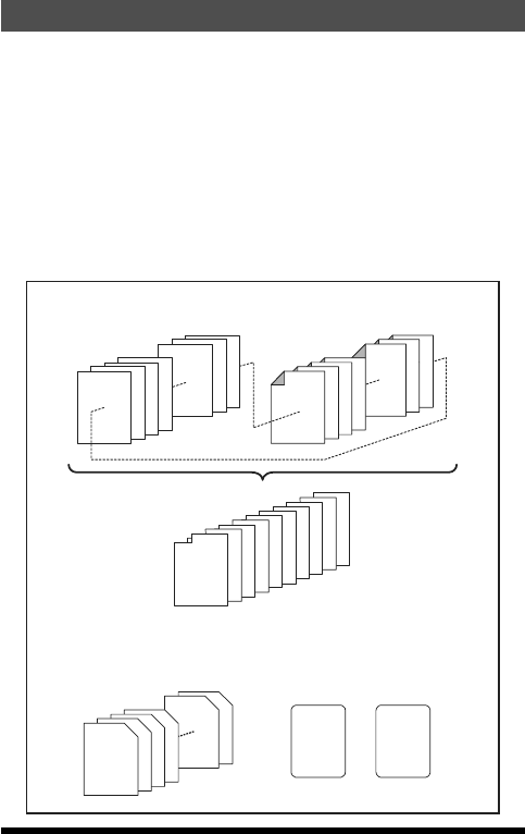
Memory Mode
The FT-25R/E provides a wide variety of memory system resources. These
include:
• 200 “Standard” memory channels, numbered “001” through “200”.
• 2 “Home” channels, providing storage and quick recall of one prime fre-
quency on each operating band.
• 10 sets of band-edge memories, also known as “Programmable Memory
Scan” channels, labeled “L01/U01” through “L10/U10”
• 10 Memory Banks, labeled “BANK 1” through “BANK10” Each Memory
Bank can be assigned up to 200 channels from the “standard” and “PMS”
memory channels.
• 10 “Weather Broadcast” Channels.
Standard Memory Channels
(200 channels)
PMS Memory Channels
(10 Sets)
Memory Banks
(10 banks)
Weather Broadcast Channels
(10 channels)
HOME Channels
(2 channels)
4
3
2
1
198
199
200
L1/U1
L2/U2
L3/U3
L4/U4
L8/U8
L9/U9
L10/U10
Memory Bank 1
Memory Bank 2
Memory Bank 3
Memory Bank 4
Memory Bank 5
Memory Bank 6
Memory Bank 7
Memory Bank 8
Memory Bank 9
Memory Bank 10
WX 1
WX 2
WX 3
WX 4
WX 9
WX 10
144 MHz Band
FM Radio
Broadcasting
Band
+
29FT-25R/FT-25E Operating Manual
Application for FCC / IC
FCC ID: K6620663X20, IC: 511B-20663X20
Memory Storage
1. Select the desired frequency, while operating in the VFO mode.
Be sure to set up any desired CTCSS or DCS tones, as well as any de-
sired repeater offset. The power level may also be set at this time, if you
wish to store it.
2. Press and hold the [ MR] key.
A blank memory channel will be displayed automatically.
3. If it is desired to change to another channel number, press the [▲] or [▼]
key.
4. Press the Alphabet / Numeric keys to input
characters and create a “Tag” (label) for the
memory channel.
If not inputting a “Tag” (label), proceed to step 5.
• To move the cursor to the next character, press the F key.
• To correct a mistake, press the F key repeatedly until the
cursor returns to the character position.
For more details on the character/symbol, see page 38.
5. Press and hold the [ MR] key to store the frequency and settings into the
selected memory channel.
“MEM-IN” on the display will blink twice and the tone will sound to com-
plete the memory setting.
30
Memory Mode
FT-25R/FT-25E Operating Manual
Application for FCC / IC
FCC ID: K6620663X20, IC: 511B-20663X20