Yaesu Musen 20663X20 AMATEUR HANDHELD VHF RADIO - SCANNING RECEIVER User Manual OM
Yaesu Musen Co., Ltd. AMATEUR HANDHELD VHF RADIO - SCANNING RECEIVER OM
Contents
- 1. User Manual 1
- 2. User Manual 2
- 3. User Manual 3
User Manual 3
Memory Recall
1. While operating in the VFO mode, press the [ MR] key to enter the Mem-
ory mode.
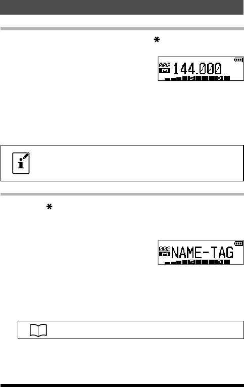
2. Press the [▲] or [▼] key to select the desired
memory channel.
3. To return to the VFO mode, press the [#VFO]
key.
When the transceiver is already set to the Memory mode, an easy way to
recall a memory channel is to enter the memory channel number using the
numeric keypad.
For example: in the Memory Mode to recall memory channel #002, press
the [2] key.
• To recall Memory Channel #200, enter “200”. To recall Pro-
grammable Memory channels “L1/U1” through “L10/U10”
enter “201/202” through “210/220”.
Changing the memory label (tag) name
1. Press the [ MR] key to recall the memory channel that you wish to label
or rename.
2. Press and hold the F key to enter the Set Mode.
3. Press the [▲] or [▼] key to select Set Mode item “20 NAME TAG”.
4. Press the F key to enter (or edit) the channel
name tag.
“NAME-TAG” message will appear.
5. Press the Alphabet / Numeric keys to enter the characters or symbols for
the memory channel “Tag” (label).
• To move the cursor to the next character, press the [▲] key.
• To correct a mistake, press the [▼] key repeatedly until the cursor returns
to the character position.
For more details on character/symbol input, see page 38.
6. Press the PTT switch to save the new setting and return to the memory
channel.
31
Memory Mode
FT-25R/FT-25E Operating Manual
Application for FCC / IC
FCC ID: K6620663X20, IC: 511B-20663X20
HOME Channel Memory Recall
A “HOME” channel memory is provided for each operating band, to allow
quick recall of a favorite operating frequency on each band. The default
home channels are below:
Default Home Channels
Band Frequency
144 MHz Band 144.000 MHz
FM Radio Band 95.000 MHz
1. Press the F key, then press the [P1] key.
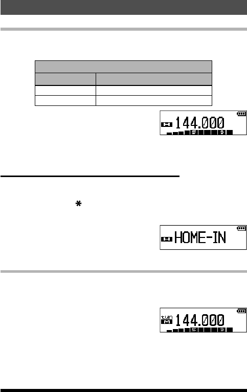
The default home channel, as listed above,
is displayed.
2. Press the F key, then press the [P1] key to exit to normal operation.
Repeat this process to recall the HOME channel on any operating band.
Changing the Home Channel Frequency
The home channel frequencies may be changed from the default settings.
1. While operating in the VFO mode, select the desired frequency.
2. Press and hold the [ MR] key.
A blank memory channel will be displayed.
3. Press the [P1] key.
• “HOME-IN” will be displayed, and then exit
to normal operation.
• The home channel frequency is changed and overwriting is complete.
Memory Offset Tuning
Once a particular memory channel is recalled, it is easy to tune off that chan-
nel, as though you were in the “VFO” mode.
1. Recall the memory channel.
2. Press the [#VFO] key to activate the “Memory
Channel Tuning” feature.
The Memory Channel number on the LCD
display will be replaced by “tun”.
32
Memory Mode
FT-25R/FT-25E Operating Manual
Application for FCC / IC
FCC ID: K6620663X20, IC: 511B-20663X20
When an alpha-numeric Tag is shown in place of the
memory channel operating frequency display, the display
will automatically revert to display the operating frequen-
cy along with the “tun” indication. It is not necessary to
enter the Menu and change from the alpha-numeric Tag
display to the operating frequency display.
3. Press the [▲] or [▼] key to tune to the desired frequency.
4. To return to the original memory frequency, just press the [#VFO] key.
The display will revert to a display of the alpha-numeric Tag (if any) that
may have originally appeared on the LCD.
To store the new frequency while using Memory Offset Tun-
ing, press and hold the [ MR] key (per the normal memory
storage procedure). The next-available clear memory location
will be displayed. Then press and hold the [ MR] key again
to save the new frequency the available memory channel.
Deleting Memories
All excerpt the Memory Channel “001” and the Home Channels may be easi-
ly deleted.
Once deleted, the channel data cannot be recovered, so
make a note of the information (Memory Channel settings,
etc), before deleting the memories.
1. Press and hold the F key to enter the Set Mode.
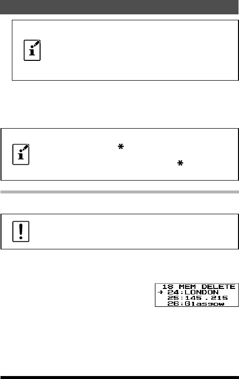
2. Press the [▲] or [▼] key to select Set Mode item “18 MEM DEL”.
3. Press the F key to enable adjustment of this Item.
4. Press the [▲] or [▼] key to select the memo-
ry channel to be “deleted”.
5. Press the F key to delete the selected mem-
ory channel.
6. Press the PTT switch to return to normal operation.
33
Memory Mode
FT-25R/FT-25E Operating Manual
Application for FCC / IC
FCC ID: K6620663X20, IC: 511B-20663X20
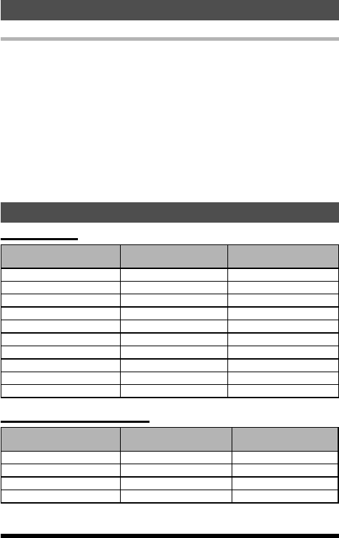
Weather Broadcast Channels
In the USA, the VHF Weather Broadcast Station Memory Channel Bank has
been pre-programmed at the factory for immediate access to NOAA weather
information stations.
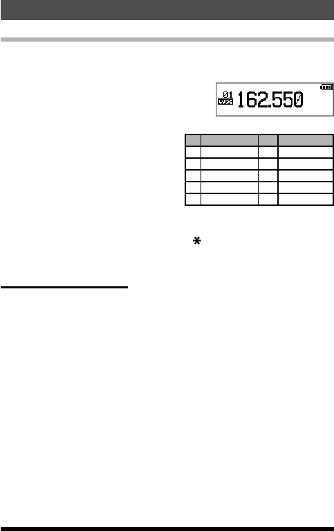
1. Press and hold the [1] key to recall the
Weather Broadcast Memory Bank.
2. Press the [▲] or [▼] key to select the desired
Weather Broadcast channel.
3. To scan for additional or stronger
Weather stations, just press the PTT
switch (or press and hold the [▲] or
[▼] key).
When the scanner pauses on a sta-
tion, press the PTT switch once to
halt the scan, or press it again to re-
start the scan.
CH Frequency CH Frequency
01 162.550 MHz 06 162.500 MHz
02 162.400 MHz 07 162.525 MHz
03 162.475 MHz 08 161.650 MHz
04 162.425 MHz 09 161.775 MHz
05 162.450 MHz 10 163.275 MHz
4. To return to normal operation, press the [ MR] key, or press and hold the
[1] key again.
Severe Weather Alert
In the event of extreme weather disturbances, such as severe thunderstorms
and hurricanes, the NOAA (National Oceanic and Atmospheric Administra-
tion) sends a weather alert accompanied by a 1050 Hz tone and subsequent
weather report on one of the NOAA weather channels.
34
Memory Mode
FT-25R/FT-25E Operating Manual
Application for FCC / IC
FCC ID: K6620663X20, IC: 511B-20663X20
Scanning
The FT-25R/E makes available scanning of the stored memory channels, or
scanning of the entire operating band, or scanning of a programmable sub
band portion. Scanning will halt when signals are encountered, and commu-
nication may be initiated on that frequency.
Operation is basically the same in each of the above scanning modes. Be-
fore beginning, take a moment to select the way the scanning will resume
after it halts on a signal.
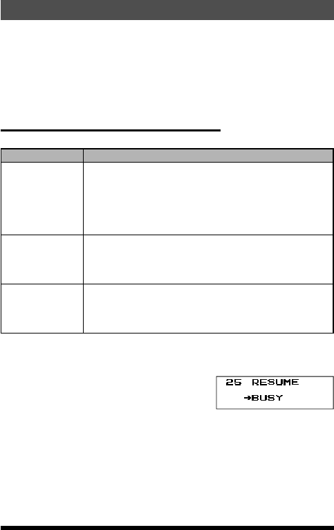
Setting the Scan-Resume Technique
Three options for the Scan-Resume mode are available:
Display Description
BUSY
(default setting)
In BUSY mode, the scanner will halt on a signal it en-
counters. Scanning will resume one second after the
other station signal ceases transmitting. In the case
of constant-carrier signals like Weather Station broad-
casts, the scanner will likely remain on this frequency
indefinitely.
HOLD
In HOLD mode, the scanner will halt on a signal it en-
counters.
Scanning will only resume when it is manually re-initiat-
ed.
TIME
In TIME mode, the scanner will halt on a signal it en-
counters, scanning will resume after five seconds even
if a signal is still on the frequency. To cancel scanning,
press the the PTT switch, [▲] or [▼] key.
1. Press and hold the F key to enter the Set mode.
2. Press the [▲] or [▼] key to select Set Mode Item “25 RESUME”.
3. Press the F key to enable adjustment of this Set Mode Items.
4. Press the [▲] or [▼] key to select the desired
scan-resume mode.
5. Press the PTT switch to save the setting and
exit to normal operation.
35FT-25R/FT-25E Operating Manual
Application for FCC / IC
FCC ID: K6620663X20, IC: 511B-20663X20
VFO Scanning
The FT-25R/E provides two VFO scanning functions: “Manual VFO Scan-
ning” and “Programmed Mode (VFO) Scanning.”
Manual VFO Scan
1. If necessary, press the [ MR] key to change to the VFO mode.
2. Press and hold the [▲] or [▼] key to initiate upward or downward scanning,
respectively.
3. When scanning encounters a signal strong enough to open the squelch,
the scanner will halt temporarily; the decimal point of the frequency display
will blink to indicate this “Resuming” condition.
4. The scanning will resume according to the Scan-Resume mode selected in
the Set Mode Item “25:RESUME”.
5. To cancel scanning, press the PTT switch, [▲] or [▼] key.
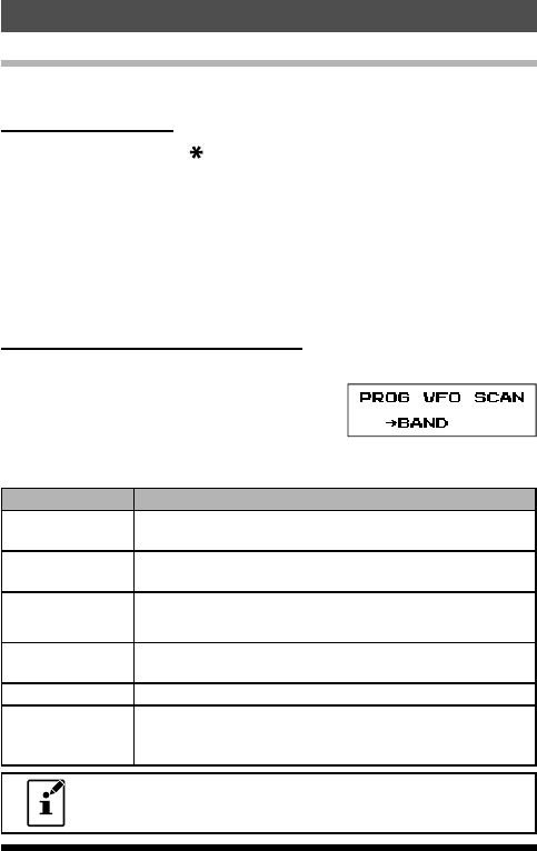
Programmed Mode (VFO) Scan
1. Press and hold the [#VFO] key.
2. Press the [▲] or [▼] key to select the band-
width for Programmed Mode (VFO) scanner.
Available selections are ±1 MHz, ±2 MHz, ±5 MHz, ALL, PMS-X, and
BAND.
Display Description
BAND
(default setting)
The scanner will sweep frequencies on the current op-
erating band.
±1MHz The scanner will sweep ±1 MHz from the operating fre-
quency.
±2MHz
The scanner will sweep ±2 MHz from the operating fre-
quency.
±5MHz The scanner will sweep ±5 MHz from the operating fre-
quency.
ALL The scanner will sweep all frequencies.
PMS-X
The scanner will sweep frequencies designated by the
currently selected PMS (Programmable Memory Scan)
frequency pair.
PMS-X will appear in the [#VFO] selections after setting a
PMS frequency pair.
36
Scanning
FT-25R/FT-25E Operating Manual
Application for FCC / IC
FCC ID: K6620663X20, IC: 511B-20663X20

3. Press the [#VFO] key to save the new setting and return to normal oper-
ation.
4. Press the F key, then press the [#VFO] key to start scanning.
5. When scanning encounters a signal strong enough to open the squelch,
the scanning will halt temporarily; the decimal point of the frequency display
will blink during this “Pause” condition.
6. The scanner will then resume according to the Scan-Resume mode select-
ed in the “RESUME” setting.
7. To cancel scanning, press the PTT switch, [▲] or [▼] key.
37
Scanning
FT-25R/FT-25E Operating Manual
Application for FCC / IC
FCC ID: K6620663X20, IC: 511B-20663X20
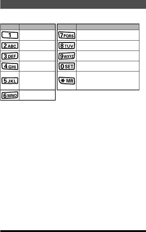
Input Character/Symbol List
On a character inputting display such as the memory mode “tag” display, the
characters and symbols may be input as below:
Key Key Assignment Key Key Assignment
1 7 P Q R S p q r s
2 A B C a b c 8 T U V t u v
3 D E F d e f 9 W X Y Z w x y z
4 G H I g h i 0 (blank character)
5 J K L j k l Û + - , . / : ; @ (blank character)
6 M N O m n o
38 FT-25R/FT-25E Operating Manual
Application for FCC / IC
FCC ID: K6620663X20, IC: 511B-20663X20
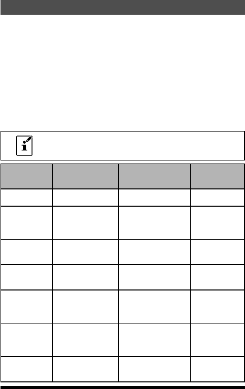
Set (Menu) Mode
The FT-25R/E Set Mode, already partially described in the previous chap-
ters, may be activated to select or change various transceiver functions.
Many of the useful parameter congurations have not been fully detailed in
this manual. Refer to the chart below for a list of the Set Mode Items and
their various parameters.
1. Press and hold the F key to enter the Set Mode.
2. Press the [▲] or [▼] key to select the Set Mode Item to be adjusted.
3. Press the F key momentarily to enable adjustment of the Set Mode Item.
4. Press the [▲] or [▼] key to adjust or select the parameter to be changed
on the Set Mode Item selected in above step.
5. After completing your selection and adjustment, press the PTT switch mo-
mentarily to save the new setting and exit to normal operation.
Press and hold the F key to move from the lower menu con-
tents to the upper menu contents in the Set Mode.
Item
(lower menu
item)
Function Values Default Value
1 APO Setting of the Automatic
Power-Off feature.
OFF / 0.5H to 12.0H
(Step 0.5H)
OFF
2 ARTS Selects the Beep
option and the Polling
Interval during ARTS™
operation.
BEEP= INRANG /
ALWAYS / OFF
INTV= 25SEC / 15SEC
BEEP=OFF
INTV= 25SEC
3 BATTSAVE Selects the Receive-
mode Battery Saver
interval (“sleep” ratio)
200mS / 300mS / 500mS
/ 1SEC / 2SEC / OFF
200mS
4 B-CH.L/O Enables/Disables the
Busy Channel Lock-
Out feature.
OFF / ON OFF
5 BEEP Beep function Enable/
Disable on presssing
the keypad, or stopping
the receiver scanning.
KEY+SC / KEY / OFF KEY+SC
6 BELL Select the number of
CTCSS/DCS/PAGER/
ARTS™ Bell ringer
repetitions.
OFF / 1Time / 3Times/
5Times / 8Times /
CONTINUE
OFF
7 COMPANDE
(COMPANDER)
Enables/Disables the
Voice Compander
feature
OFF / ON OFF
39FT-25R/FT-25E Operating Manual
Application for FCC / IC
FCC ID: K6620663X20, IC: 511B-20663X20

Item
(lower menu
item)
Function Values Default Value
8 CTCSS
(CTCSS TONE)
Setting the CTCSS
Frequency TX and RX
50 CTCSS tones / OFF TX=100.0Hz
RX=100.0Hz
9 CW ID CW Identifier during
ARTS™ operation.
TX= OFF / ON
ID= ------ (6 characters)
TX= OFF
ID= blank
10 DC VOLT displays Battery DC
Voltage. − −
11 DCS CODE Setting the DCS CODE
TX and RX
104 DCS CODEs / OFF TX=023
RX=023
12 DTMF SET Selects the MANUAL
or AUTO DTMF tones.
Setting the DTMF
autodialer sending
delay time and Speed.
MODE= MANUAL /
AUTO
DELAY= 50mS / 250mS /
450mS / 750mS
/ 1000mS
SPEED= 50mS / 100mS
M=MANUAL
D=450mS
S=50mS
13 DTMF WRT Programming to DTMF
autodialer. − −
14 EDG.BEEP Enables/Disables the
Band-edge beeper
while selecting the
frequency via the [▲]
or [▼] key.
BEEP OFF / BEEP ON BEEP OFF
15 KEY LOCK Keyboard Lock function KEY / PTT / P+K KEY
16 LAMP Selects the LCD/
Keypad Lamp mode.
5secKey / 10secKey /
30secKey / CONT / OFF
5secKey
17 LED Selects the enable or
disable TX/BUSY LED
function.
TX= ON / OFF
BUSY= ON/ OFF
TX=ON
BUSY=ON
18 MEM DEL
(MEM
DELETE)
Deletes Memory
Channel − −
19 MON/T-CL
(MON/T-CALL)
Selects the MONI
or T.CALL switch
function.
MONITOR / T-CALL1750
/ T-CALL2100 /
T-CALL1000 /
T-CALL1450
MONITOR (*) or
T-CALL1750 (*)
20 NAME TAG Renames Alpha-
Numeric “Tags” for the
Memory channels.
− −
40
Set (Menu) Mode
FT-25R/FT-25E Operating Manual
Application for FCC / IC
FCC ID: K6620663X20, IC: 511B-20663X20

Item
(lower menu
item)
Function Values Default Value
21 PAGER Setting the TX CTCSS
of 2 tone and the RX
CTCSS of 2 tone.
Enables/disables the
Answer Back function.
TX: ** **
RX: ** **
ACK : ON / OFF
TX=05 47
RX=05 47
ACK=OFF
22 PASSWORD Enables/disables the
Password feature
OFF / ON / OFF
23 PRI.RVT Enables/disables the
Priority Revert feature.
RVT.OFF / RVT. ON RVT.OFF
24 REPEATER ARS / MODE / SHIFT
function setting
ARS= ON / OFF
MODE=SIMPLEX / +RTP
/ -RTP
SHIFT= 0.05 MHz - 99.95
MHz (per 50KHz)
ARS=ON
MODE=SIMPLEX
SHIFT=**.**M (*)
25 RESUME Selects the Scan
Resume mode.
BUSY / HOLD / TIME BUSY
26 RF SQL Adjusts the RF Squelch
threshold level.
S-1 / S-2 / S-3 / S-4 / S-5
/ -6 / S-8 / S-FULL / OFF
OFF
27 SCN.LAMP Enables/Disables
the Scan lamp while
paused.
ON / OFF ON
28 SKIP
(SKIP SCAN)
Selects the Memory
Scan “Skip” channel-
selection mode.
− −
29 SQL TYPE Selects the Tone
Encoder and/or
Decoder mode.
OFF / R-TONE / T-TONE
/ TSQL / REV TN / DCS /
PAGER
OFF
30 STEP Setting of the frequency
steps.
5 / 6.25 / 10 / 12.5 / 15 /
20 / 25 / 50 / 100 kHz, or
AUTO
AUTO
31 TOT Setting of the TOT
time.
1 min - 30 min (per 1
min) or OFF
3min
32 TX PWR Selects TX Power HI(5W) / MID(2.5W) /
LOW(0.5W)
HI(5W)
41
Set (Menu) Mode
FT-25R/FT-25E Operating Manual
Application for FCC / IC
FCC ID: K6620663X20, IC: 511B-20663X20

Item
(lower menu
item)
Function Values Default Value
33 TX SAVE Enables/Disables the
Transmitter Battery
Saver.
SAVE OFF / SAVE ON SAVE OFF
34 VFO.SPL Enables or disables
“VFO Split” operation.
VSP.OFF / VSP.ON VSP.OFF
35 VOX Enable / Disable VOX
function.
VOX OFF / VOX ON VOX OFF
36 WFM.RCV Broadband FM
Radio(WFM) function
Enables/Disables
WFM.ON / WFM.OFF WFM.ON
37 WIDE/NAR Select Wide (±5 kHz)
or Narrow (±2.5 kHz)
TX Deviation.
WIDE / NARROW WIDE
38 WX ALERT Enables/Disables the
Weather Alert Scan
feature.
ALT.OFF / ALT. ON ALT.OFF
39
SCRAMBLE(*)
Inversion scrambling
(Encryption)
SCRB.OFF/SCRB.ON SCRB.OFF
(*) : This function may be displayed, depending on the transceiver ver-
sion.
42
Set (Menu) Mode
FT-25R/FT-25E Operating Manual
Application for FCC / IC
FCC ID: K6620663X20, IC: 511B-20663X20

Troubleshooting
If you suspect a malfunction, check the following items before requesting a
repair.
The transceiver does not turn on.
• Is the battery depleted?
• Charge the battery pack after purchase, and when the transceiver has not
been used for a long time.
• Is the battery pack properly attached?
Refer to “Installing the Battery Pack” and securely mount the battery pack.
There is no sound.
• Is the squelch level (or S meter squelch) set too high?
Press the MONI/T.CALL key and verify that you can hear white noise.
Adjust the squelch level (or S meter squelch) when receiving a weak sig-
nal.
• Is the volume low?
Rotate the PWR/VOL knob clockwise to increase the volume.
• Is the tone squelch or DCS on?
When the tone squelch or DCS is on, the sound is not output until the
transceiver receives a signal containing the same tone frequency or DCS
code set.
For more details on the DCS code, refer to the Advance Manual.
There is no transmission of radio waves.
• Are you pressing the PTT switch properly?
• Is the PTT lock on?
• Is the Busy TX Block (BCLO function) on?
When the Busy TX Block (BCLO function) is on, transmission is inhibited
when receiving a signal, even if the PTT switch is pressed. Wait until the
signal being received stops and then press the PTT switch.
• Is the transmission frequency on a ham radio band?
Transmission cannot be performed on the FM Radio Broadcast Band/Infor-
mation Radio Band.
• Is the voltage of the battery pack correct?
Check the remaining charge on the battery pack.
In addition, using an inadequate power supply where voltage drops during
transmission will prevent the FT-25R/E from operating at full capability.
The keys or DIAL do not respond.
• Is the Keypad Lock or PTT Lock on?
43FT-25R/FT-25E Operating Manual
Application for FCC / IC
FCC ID: K6620663X20, IC: 511B-20663X20

The battery pack cannot be charged or battery power
depletes immediately after charging.
• Is the battery pack being charged with a charger specied by Yaesu?
Charge the battery pack using the accessory battery charger (SAD-20B/
C/U/G) or the rapid charge cradle (SBH-22).
• Is the battery pack in use exhausted?
If the “Charging Error” appears on the desktop charger lamp when
charging, there is a chance the battery pack is over discharged. If the er-
ror is repeatedly displayed after charging the battery pack several times,
the battery pack may have reached its service life or be defective. Battery
packs are consumables. Please replace an exhausted battery pack with
a new one immediately. Battery packs can be charged and reused up to
approximately 300 times.
Some specic combinations of signals may cause internal beats (“birdies”)
from
high frequencies, caused by the internal oscillator. This is not a malfunction.
(See the calculation formula below: “n” is for the arbitrary integer). Also, de-
pending on the combination of simultaneously received signals, there may
be uctuations in receive sensitivity.
• Receive Frequency = 13 MHz × n multiplicative
• Receive Frequency = 19.2 MHz × n multiplicative
44
Troubleshooting
FT-25R/FT-25E Operating Manual
Application for FCC / IC
FCC ID: K6620663X20, IC: 511B-20663X20

Specifications
General
Frequency Ranges: RX 136 - 174 MHz
TX 144 - 146 (148) MHz
FM Broadcast 65-108 MHz
Channel Steps: 5 / 6.25 / 10 / 12.5 / 15 / 20 / 25 / 50 / 100 kHz
Frequency Stability: ±5 ppm (–10 °C to +60 °C, +14 F to +140F )
Repeater Shift:
±600 kHz (144 MHz), ±1.6 / 5.0 / 7.6 MHz
Emission Type: F2D, F3E
Antenna Impedance: 50 Ohms
Supply Voltage: Nominal: 7.4V DC, Negative Ground
Current Consumption: 215 mA (Receive) 200 mW Output
(Approx. @7.2V) 110 mA (Standby, Saver Off)
30 mA (Standby, Saver On)
4 mA (Auto Power Off)
1.5 A (5 W Tx , 144 MHz) 7.4 V DC
Operating Temperature: – 4 °F to +14 °F (– 20 °C to + 60 °C)
Case Size:
2.1” (W) x 4.1” (H) x 1.2” (D) (52.5 x 104.5 x 31 mm)
(W/O knob and antenna)
Weight: 9.17 Oz (260 g) with SBR-25LI and antenna
Transmitter
RF Power Output: 5.0 W (High) / 2.5 W (Middle) / 0.5 W (Low)
(@ 7.4 V with SBR-25LI)
Modulation Type: Variable Reactance F2D, F3E
Maximum Deviation: ±5.0 kHz (F2D, F3E)
Spurious Emission: At least 60 dB down (@ High and Middle power)
At least 40 dB down (@ Low power)
Microphone Impedance: 2 kOhms
45FT-25R/FT-25E Operating Manual
Application for FCC / IC
FCC ID: K6620663X20, IC: 511B-20663X20
Receiver
Circuit Type: Direct-Conversion
Sensitivity : 0.2 µV for 12 dB SINAD (140 - 150 MHz, NFM)
0.2 µV for 12 dB SINAD (420 - 470 MHz, NFM)
Selectivity: 12 kHz / 35 kHz (–6 dB /–60 dB)
AF Output: 0.8 W @ 16 ohms for 10% THD (@ 7.4 V)
(Internal SP Max Power 1 W)
0.8 W @ 16ohms for 10%THD (@ 7.4 V)
(EXT SP Jack Max Power 1 W)
Specifications are subject to change without notice, and are guaranteed with-
in the 144 MHz amateur band only. Frequency ranges will vary according to
transceiver version; check with your dealer.
“AUTO” Mode Preset Operating Parameter
USA Version
Frequency Range (MHz) Mode step
136.000-144.000 FM 12.5 kHz
144.000-148.000 FM 5k Hz
148.000-156.000 FM 12.5 kHz
156.000-157.450 FM 25 kHz
157.450-160.600 FM 12.5 kHz
160.600-160.975 FM 25 kHz
160.975-161.500 FM 12.5 kHz
161.500-162.900 FM 25 kHz
162.900-174.000 FM 12.5 kHz
65.000-108.000 (RX only) WFM 100kHz
Asian/European Version
Frequency Range (MHz
)
Mode step
136.000-160.600 FM 12.5 kHz
160.600-162.025 FM 25 kHz
162.025-174.000 FM 12.5 kHz
65.000-108.000 (RX only) WFM 100 kHz
46
Specifications
FT-25R/FT-25E Operating Manual
Application for FCC / IC
FCC ID: K6620663X20, IC: 511B-20663X20

1. Changes or modifications to this device that are not expressly
approved by YAESU MUSEN could void the user’s authorization
to operate this device.
2. This device complies with part 15 of the FCC Rules. Operation
is subject to the following two conditions: (1) This device may
not cause harmful interference, and (2) this device must accept
any interference including received, interference that may cause
undesired operation.
3. The scanning receiver in this equipment is incapable of tuning,
or readily being altered, by the User to operate within the
frequency bands allocated to the Domestic public Cellular
Telecommunications Service in Part 22.
This device complies with Industry Canada license-exempt RSS
standard(s). Operation is subject to the following two conditions: (1)
this device may not cause interference, and (2) this device must
accept any interference, including interference that may cause
undesired operation of the device.
Le présent appareil est conforme aux CNR d’Industrie Canada
applicables aux appareils radio exempts de licence. L’exploitation
est autorisée aux deux conditions suivantes : (1) l’appareil ne
doit pas produire de brouillage, et (2) l’utilisateur de l’appareil doit
accepter tout brouillage radioélectrique subi, même si le brouillage
est susceptible d’en compromettre le fonctionnement.
DECLARATION BY MANUFACTURER
The Scanner receiver is not a digital scanner and is incapable of
being converted or modified to a digital scanner receiver by any
user.
WARNING: MODIFICATION OF THIS DEVICE TO RECEIVE
CELLULAR RADIOTELEPHONE SERVICE SIGNALS IS
PROHIBITED UNDER FCC RULES AND FEDERAL LAW.
47FT-25R/FT-25E Operating Manual
Application for FCC / IC
FCC ID: K6620663X20, IC: 511B-20663X20

Note
48 FT-25R/FT-25E Operating Manual
Application for FCC / IC
FCC ID: K6620663X20, IC: 511B-20663X20

Note
49
FT-25R/FT-25E Operating Manual
Application for FCC / IC
FCC ID: K6620663X20, IC: 511B-20663X20

1612H-XX
Printed in Japan
Copyright 2016
YAESU MUSEN CO., LTD.
All rights reserved.
No portion of this manual
may be reproduced
without the permission of
YAESU MUSEN CO., LTD.
YAESU MUSEN CO., LTD.
Tennozu Parkside Building
2-5-8 Higashi-Shinagawa, Shinagawa-ku, Tokyo 140-0002 Japan
YAESU USA
6125 Phyllis Drive, Cypress, CA 90630, U.S.A.
YAESU UK
Unit 12, Sun Valley Business Park, Winnall Close
Winchester, Hampshire, SO23 0LB, U.K.
Application for FCC / IC
FCC ID: K6620663X20, IC: 511B-20663X20