Yaesu Musen 20693X20 FM TRANSCEIVER User Manual Operating Manual
Yaesu Musen Co., Ltd. FM TRANSCEIVER Operating Manual
UserManual.wiki
>
Yaesu Musen
>
20693X20 User Manual
Operating Manual
Navigation menu
Upload a User Manual
Namespaces
Wiki Guide
HTML
PDF
Info
Views
User Manual
Discussion / Help
Navigation
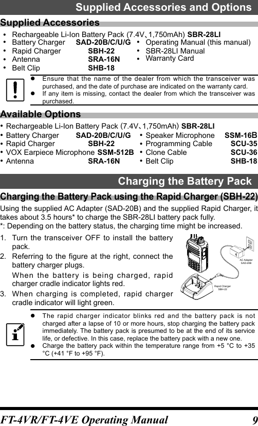
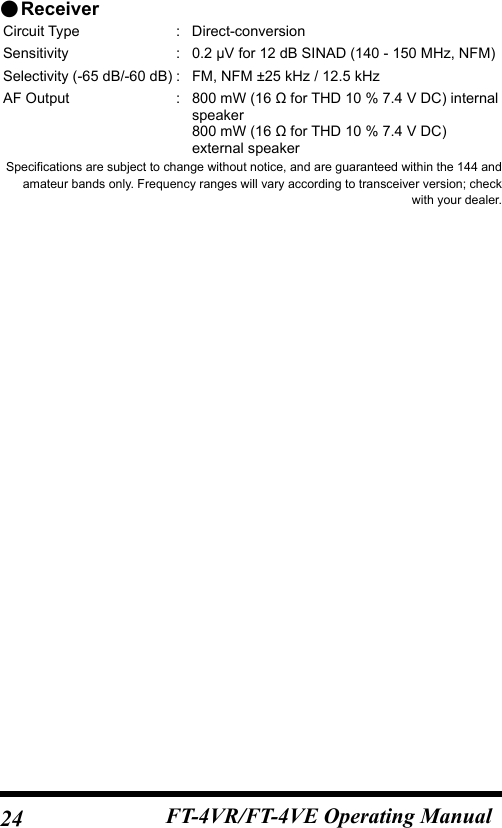
![10 FT-4VR/FT-4VE Operating Manual ●Approximate Operating Time and Remaining Charge Level IndicationApproximate operating time for the transceiver with the fully charged lithium-Ion battery pack (SBR-28LI), and the indication of the remaining charge level of the battery is shown in the below table:Frequency band Band in Use Charge Level Indication (Icon)144 MHz band Approx. 9.0 hours :Full battery power :Enough battery power : Battery is depleted. Charge battery. : (When blinking) Charge battery immediately.FM Broadcast Band Approx. 12.0 hoursThe battery charge level calculations are based on an operating cycle of: Transmitting 6 seconds (5 W): Receiving 6 seconds (VOL Level 16): Stand By 48 seconds (RX SAVE 1:5)OperationChanging between the VFO-A mode and VFO-B modePress the [#VFO] key repeatedly to toggle the frequency control between the VFO-A mode and VFO-B mode.To listen to the FM broadcast radio, press the [#VFO] key to change to the VFO-B. FM broadcast band may be received signals in the VFO-B mode only.Tuning to a Frequency(Two ways) ●Press the [] key or [] key to tune the frequency.By pressing the function key and then press the [] key or the [] key, the frequency will change in 1 MHz steps. ●Press the numeric keys to enter the frequency digits in order, beginning with the 100 MHz digit.When entering a frequency using the numeric keys, it may be canceled by pressing the PTT switch.](https://usermanual.wiki/Yaesu-Musen/20693X20/User-Guide-3771054-Page-3.png)
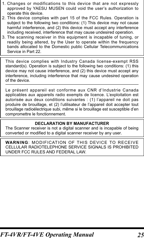
![11FT-4VR/FT-4VE Operating ManualChanging the Frequency Step ("AUTO" for normal operation)Pressing the [] key or [] key, the frequency step may be changed. Normally, the factory default setting will provide a good frequency step.Pressing and holding the Function key →Pressing the key →Pressing the Function key(Entering the Set mode) (Selecting "37 STEP")1. Press the [] key or the [] key to select the desired frequency step.2. Press the PTT switch to save the setting and return to normal operation.In the default setting, of the frequency step is set to “AUTO”, which automatically provides a suitable frequency step according to the frequency band.Adjusting the squelch settingThe squelch level may be adjusted to mute the background noise when no signal is present.1. Press the function key and then press the MONI/T-CALL switch.“LVL □”(0-15) appear on the display.2. Press the [] key or [] key to a level at which the background noise is muted.3. Press the PTT switch to save the setting. zThe default setting is“LVL 2”. zWhen the squelch level is increased, the noise is more likely to be silenced, but it may become more difficult to receive weak signals.Transmission1. While pressing and holding the PTT switch, speak into the microphone.TX/BUSY indicator lights red during the transmission.If the PTT switch is pressed when a frequency other than the amateur ham radio band is selected, an alarm tone (beep) will be emitted and “ERROR” appears on the LCD, disabling transmission.2. Release the PTT switch to return to receive mode.When receiving a signal, the TX/BUSY Indicator lights red.MicrophoneTX/BUSY lamp](https://usermanual.wiki/Yaesu-Musen/20693X20/User-Guide-3771054-Page-4.png)
![12 FT-4VR/FT-4VE Operating ManualChanging the Transmission Power LevelPressing and holding the Function key →Pressing the key →Pressing the Function key(Entering the Set mode) (Selecting "40 TX PWR")1. Press the [] or [] to select one of the following transmission power levels.TX PO Level Icon PO meterHIGH (5W)*(off)MID (2.5W)LOW (0.5W)*The default setting.2. Press the PTT switch to save the setting and return to the normal operation.The transmission power level may be set separately for each frequency band.Locking Keys and PTT switch1. Press and hold the [6] key, “LOCK” is displayed on the LCD for one second, the “ ” icon appears on the LCD, and then the keys and PTT switch are locked. zThe keys and the PTT switch may be selected to be locked using Set Mode [18 LOCK]( 20. The default setting is the [LK KEY] (the keys are locked). zThe [MONI/T-CALL] switch and the PWR/VOL knob cannot be locked.2. Press the [6] (LOCK) switch again, “UNLOCK” will be displayed on the LCD, the keys and the PTT switch are unlocked.Tone Calling (1750 Hz)If your transceiver is FT-4VE (European version), press and hold in the MONI/T-CALL switch to generates the 1750 Hz burst tone to access the European repeater.The transmitter will automatically be activated, and the 1750 Hz audio tone will be superimposed on the carrier. Once the repeater has been accessed, release the MONI/T-CALL switch, and use the PTT switch to activate the transmitter thereafter.](https://usermanual.wiki/Yaesu-Musen/20693X20/User-Guide-3771054-Page-5.png)
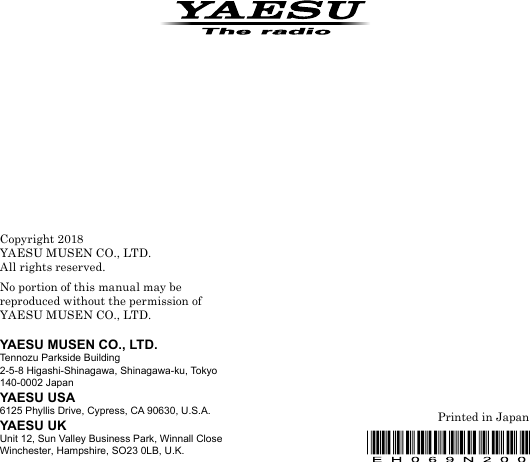
![13FT-4VR/FT-4VE Operating ManualIf needed, the FT-4VR (USA/Asian version), may be set to access repeaters which require a 1750 Hz burst tone by setting the MONI/T-CALL switch to serve as a “Tone Call” switch instead. To change the configuration of the MONI/T-CALL switch, use Set Mode [19 M/T-CL] ( 20).Using the MemoryThe FT-4VR/VE transceiver incorporates Large-capacity memory channels that can register the operating frequency, communication mode, and other operational information. 200 Memory Channels 2 Home Channels 10 pairs PMS Memory channelEach memory channel can store the following information.Operating frequency Frequency steps TX output powerMemory tagRepeater information Tone information DCS informationSkip memory information10 Memory Banks, labeled “BANK 1” through “BANK10” Each Memory Bank can be assigned up to 200 channels from the “standard” and “PMS” memory channels.2001994321L10/U10L09/U09L4/U4L3/U3L2/U2L1/U1Memory Channel Configuration of the TransceiverMemory channels(200 channels)Home channels(2 channels)Memory banks(10 banks)Up to 200 memory channels can beregistered to each bank.(One memory channel can be registered to several memory banks)PMS memory channels(10 sets)For additional details on the Skip Search Memory, PMS memory channel and Memory Bank, refer to the Advanced Manual which may be downloaded from the Yaesu website.](https://usermanual.wiki/Yaesu-Musen/20693X20/User-Guide-3771054-Page-6.png)
![14 FT-4VR/FT-4VE Operating ManualCAUTIONS!The information registered to memory channels can be corrupted by incorrect operation, static electricity, or electrical noise. Also, it can be erased in the event of a failure or repair. Be sure to keep a record of the settings on paper.Registering to Memory Channels1. Set the frequency and the communication mode to be registered to a memory channel.2. Press and hold the [ MR] key.A blank memory channel will be displayed auto-matically.3. Press the [] key or [] key to select the desired channel number.4. Input the memory tagUse the numeric keys to input the characters.If not inputting a “Tag” (label), proceed to step 5.Input CharacterExample: Press the [2] key repeatedly to toggle among the following available characters.2 → A → B → C → a → b → c → 2 → Memory ChannelNumberPress the function key to move the cursor.5. Press and hold the [ MR].The beep sounds and the memory is saved.Memory Recall1. While operating in the VFO mode, press the [ MR] key to enter the Memory mode.The memory channel most recently used appears on the LCD.2. Press the [▲] or [▼] key to select the desired memory channel.When the transceiver is already set to the Memory mode, an easy way to recall a memory channel is to enter the memory channel number using the numeric keypad.3. Press the [ MR] key to exit the memory mode, and return to the normal operation.](https://usermanual.wiki/Yaesu-Musen/20693X20/User-Guide-3771054-Page-7.png)
![15FT-4VR/FT-4VE Operating ManualPress and hold the MONI/T.CALL key and the PTT switch simultaneously, while turning the radio ON to enter the preferred operating mode.In the preferred operating mode, press the [] key or [] key to select the [F5 M-ONLY], then press the function key to enter the Memory Channel Only mode. To cancel the Memory Channel Only mode, press the [] key or [] key to select the [F5 M-ONLY], then press the function key again.Clearing MemoriesPressing and holding the Function key →Pressing the key →Pressing the Function key(Entering the Set mode) (Selecting "20 MEM DEL")1. Press the [] key or [] key to select the memory channel from which the data is to be cleared.2. Press the function key.“del OK” appears on the LCD and the memory channel is cleared.3. Press the PTT switch to save the setting and return to the normal operation. Data on memory channel One, and the Home channel may not be cleared.Recalling the Home Channels1. Press the Function key, and then press the [P1] key.“H” and the home channel frequency of the cur-rently selected band appears on the LCD.2. Press the Function key, and then press the [P1] key to return to the previous frequency.Home channelindicationChanging the Home Channel Frequency1. Set the frequency and the operating mode you want to store as a home channel.2. Press and hold the [ MR] key.A blank memory channel will be displayed automatically.3. Press the [P1] key."HOM-IN" is displayed, desired Home channel frequency is changed and re-turned to normal operation.](https://usermanual.wiki/Yaesu-Musen/20693X20/User-Guide-3771054-Page-8.png)
![16 FT-4VR/FT-4VE Operating ManualMemory Channel ScanningThe receiver may be set to scan memory channels:1. While operating in the VFO mode, press the [ MR] key to enter the Memory mode.2. Press and hold the [▲] key or [▼] key.Scanning starts toward higher memory channel numbers.If the scanner halts on an incoming signal, the back light will turn ON and the decimal point between the “MHz” and “kHz” digits of the frequency display will blink. Scanning will resume in about one second after the other station signal ceases transmitting (default setting).3. Press the PTT switch to cancel the scanning.If the scan has paused on a signal, rotating the DIAL knob will cause scanning to resume next memory channel.Setting the Receive Operation When Scanning StopsPressing and holding the Function key →Pressing the key →Pressing the Function key(Entering the Set mode) (Selecting "34 SCN.RSM")1. Press the [▲] key or [▼] key to select the operation performed after the scan stops:Display DescriptionBUSY(Default setting)In BUSY mode, the scanner will halt on a signal it encounters. Scanning will resume one second after the other station signal ceases transmitting. In the case of constant-carrier signals like Weather Station broadcasts, the scanner will likely remain on this frequency indefinitely.HOLDIn HOLD mode, the scanner will halt on a signal it encounters. Scanning will only resume when it is manually re-initiated.TIMEIn TIME mode, the scanner will halt on a signal it encounters, scanning will resume after five seconds even if a signal is still on the frequency. To cancel scanning, press the the PTT switch, [▲] or [▼] key.2. Press the PTT switch to save the setting and exit to normal operation.](https://usermanual.wiki/Yaesu-Musen/20693X20/User-Guide-3771054-Page-9.png)
![17FT-4VR/FT-4VE Operating ManualThe above setting (Set Mode [34 SCN.RSM]is common for all scanning operation.For additional details on the following functions, refer to the Advanced Manual which may be downloaded from the Yaesu website.Using Memory TagMemory name tags may be assigned to the memory channels and home channels.Using Memory BankThe transceiver allows using up to 10 memory banks to allow sorting and registering thechannels in convenient groups.Scanning FunctionThe transceiver supports the following four scanning functions:VFO ScanProgram ScanMemory Channel ScanProgrammable Memory Scan(PMS)Memory Bank ScanFor additional details on the Programmable Memory Scan (PMS) and Memory Bank Scan, refer to the Advanced Manual which may be downloaded from the Yaesu website.VFO ScanVFO scan function scans the frequencies, and detects signals.1. Press and hold the [] key or the [] to start scanning in the VFO mode.2. Press the PTT switch, [▲] or [▼] key to cancel scanning.](https://usermanual.wiki/Yaesu-Musen/20693X20/User-Guide-3771054-Page-10.png)
![18 FT-4VR/FT-4VE Operating Manual zIf the scan has paused on a signal, Turning the transceiver ON will cause scanning to resume instantly. zTo set the transceiver action when scanning stops, see “Setting the Receive Operation When Scanning Stops” on page ] ( 20).Using Set ModeThe Set Mode permits configuring the various functions according to individual operating needs and preferences.1. Press and hold the Function key.The previously selected Set Mode item is displayed.2. Press the [▲] key or [▼] key to select the desired Set Mode item.3. Press the function key, then press the [] key or [] key to change the setting.4. Press the PTT switch to save the settings and return to normal operation. zIn step 4 above, press the Function key to save the new setting and return to Set Mode item to set the other Set Mode. zOn some setting screens, key operation is different than described in the above steps (For example, inputting the characters, etc.). Refer to the Advance manual.For additional details, refer to the Advanced Manual which may be downloaded from the Yaesu website](https://usermanual.wiki/Yaesu-Musen/20693X20/User-Guide-3771054-Page-11.png)
![19FT-4VR/FT-4VE Operating ManualTables of Set Mode OperationsNo. Set Mode item DescriptionSelectable options(Options in bold are the default settings)1 APO Sets the length of time until the transceiver turns off automatically.OFF / 0.5 Hours 12Hours2 AR BEP Sets the beep option during ARTS operation. OFF / INRANG / ALWAYS3 AR INT Sets the polling interval during ARTS operation. 25 SEC / 15 SEC4 BCLO Turns the busy channel lockout function ON/OFF. BCL.OFF / BCL.ON 5 BEEP Sets the beep function on pressing the keypad, or stopping the receiver scanning. KEY+SC / KEY / OFF6 BELL Selects the number of CTCSS/DCS/PAGER/ARTS Bell ringer repetitions.OFF / 1 T / 3 T / 5 T / 8 T / CONT7 CWID Turns the CW Identifier ON/OFF during ARTS operation. TX OFF / TX ON8 CW WRT Sets the CW ID during ARTS operation.ID= (6 characters)default: blank9 DC VLT Displays the voltage. (Voltage)10 DCS.COD Sets the DCS CODE RX and TX. 104 DCS CODEs / OFFdefault: 023 R / 023 T11 DT DLY Sets the DTMF code transmission delay time.50MS / 250MS / 450MS / 750MS / 1000MS12 DT SETSelects the DTMF auto dialer memory channel and edits the DTMF code (Maximum 16 digits)d1 d913 DT SPD Sets the DTMF code transmission speed. 50MS / 100MS14 EDG.BEPTurns the the Band-edge beeper on/off.while selecting the frequency via the [▲] or [▼] key.BEP.OFF / BEP. ON15 LAMP Selects the LCD/Keypad Lamp mode. 5 SEC / 10 SEC / 30 SEC / CONT / OFF16 LED.BSY Turns the TX/BUSY lamp ON/OFF while receiving signals. BSY ON / BSYOFF17 LED.TX Turns the TX/BUSY lamp ON/OFF while transmitting signals. TX ON / TXOFF](https://usermanual.wiki/Yaesu-Musen/20693X20/User-Guide-3771054-Page-12.png)
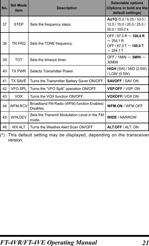
![20 FT-4VR/FT-4VE Operating ManualNo. Set Mode item DescriptionSelectable options(Options in bold are the default settings)18 LOCK Configures the lock mode setting. LK KEY / LK PTT / LK P+K19 M/T-CL Selects the function of the [MONI/T-CALL] switch.MONI / TC1750* / TC2100 / TC1000 / TC1450(*: Eurpean / Asian Version)20 MEM.DEL Deletes the memory channel 21 MEM. TAG Edits the memory channel tag. 22 PAG.ABK Turns the pager answer back Function ON/OFF ABK.OFF / ABK. ON23 PAG.CDR Specifies a personal code (receive). 01 05 50, 01 47 5024 PAG.CDT Specifies a personal code (transmit). 01 05 50, 01 47 5025 PRI.RVT Turns the Priority Revert feature ON/OFF. RVTOFF / RVT ON26 PSWD Turns the Password feature ON/OFF. PWD.OFF / PWD. ON27 PSWDWT Inputs the password. 4 digits28 RF SQL Adjusts the RF Squelch threshold level.OFF / S-1 / S-2 / S-3 / S-4 /S-5 / S-6 / S-8 / S-FULL29 RPT.ARS Turns the ARS function on/off. ARS.ON / ARS.OFF30 RPT.FRQ Sets the repeater shift width.OFF / 0.05MHz 99.95MHz (*)31 RPT.SFT Sets the repeater shift direction. SIMPLX / +RPT / -RPT32 RXSAVE Selects the Receivemode Battery Saver interval (“sleep” ratio) 200 MS 2 SEC / OFF33 SCN.LMP Turns the scan lamp ON/OFF while paused.ON / OFF34 SCN.RSM Configures the scan stop mode settings. BUSY / HOLD / TIME35 SKIP Turns the Memory Scan “Skip” channel selection mode ON/OFF. OFF / SKIP36 SQL.TYP Selects the Tone Encoder and/or Decoder mode.OFF / R-TONE / T-TONE / TSQL / REV TN / DCS / PAGER](https://usermanual.wiki/Yaesu-Musen/20693X20/User-Guide-3771054-Page-13.png)
![22 FT-4VR/FT-4VE Operating ManualRestoring to Defaults (Reset) / Setting the Preferred Operating ModeThe following reset or preferred operating modes may be selected.1. Turn the transceiver OFF.2. Press and hold the MONI/T.CALL key and the PTT switch simultaneously, while turning the transciever ON.3. When the LCD backlight comes on, release the MONI/T.CALL key and PTT switch.4. Referring to the above table, press the [▲] or [▼] key to select the desired resets or desired operating modes.Display DescriptionF1:SET RST Resets the Set Mode settings to factory defaults.F2:MEM RST Clears the Memory settings to factory defaults.F3:MB. RST Clears the Memory Bank assignments.F4:ALL RST Clears the All memories and other settings to factory defaults.F5:M- ONLY Operation on the Memory mode only.F6:CLONE Clone mode.CAUTION!Resetting the transceiver (F2 MEM RST / F4 ALL RST) will clear all memories.Please make a note of the memories (memory channel settings, etc) before resetting. zTo cancel this operation, turn the transceiver OFF. zPerform All Reset to restore all of the following Set Mode items to default.10 DCS.COD 26 PSWD 27 PSWDWT 30 RPT.FRQ 31 RPT.SFT 35 SKIP 36 SQL.TYP 37 STEP 38 TN FRQ 40 TX PWR44 W/N.DEV](https://usermanual.wiki/Yaesu-Musen/20693X20/User-Guide-3771054-Page-15.png)
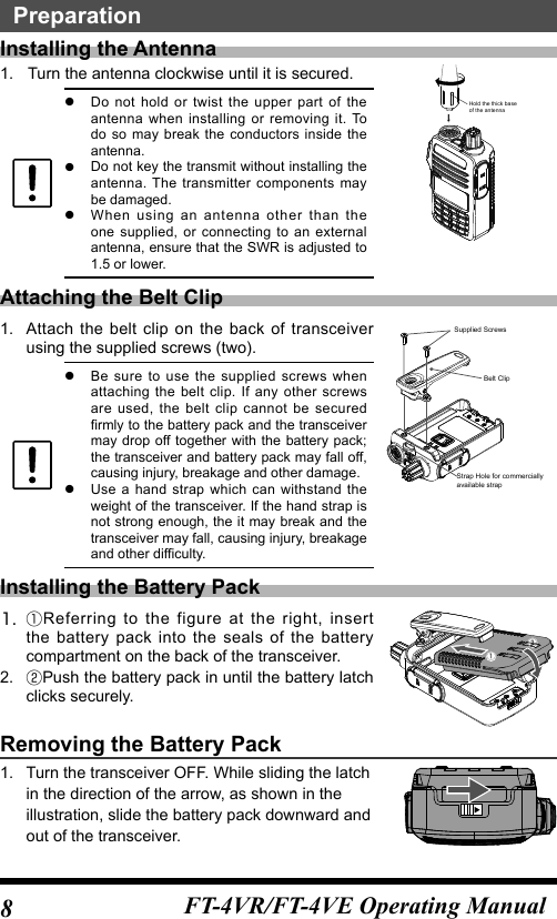
![23FT-4VR/FT-4VE Operating ManualSpecifications ●GeneralFrequency Range RX: 136 - 174MHzTX: 136 - 174 MHz (Asian version)144 - 146 MHz (European version)144 - 148 MHz (USA version) FM Broadcast: 65 - 108 MHzChannel Steps : 5/10/12.5/15/20/25/50/100kHzMode of Emission : F2DF3EF2AFrequency Stability : ±2.5ppm (−20 °C to +60 °C [−4 °F to +140 °F])Antenna Impedance : 50 ohmsSupply Voltage Nominal: 7.4 V DC, Negative Ground SBR-28LICurrent Consumption :(Approx.) 190 mA (Receive) 200 mW Output95 mA (Standby, Saver Off)23 mA (Standby, Saver On)5 mA (Auto Power Off)1.5 A (5 W Tx , 144 MHz) 7.4 V DCOperating Temperature : – 4 °F to +140 °F (– 20 °C to + 60 °C)Case Size : 2.0” (W) x 3.5” (H) x 1.2” (D) (52×90×30mm)W/O knob and antennaWeight (Approx.) : 9.17 oz (250g) with SBR-28LI and antenna ●TransmitterRF Power Output : 5.0 W (High) / 2.5 W (Middle) / 0.5 W (Low)(@ 7.4 V with SBR-28LI)Modulation Type : Variable ReactanceMaximum Deviation : ±5.0 kHzSpurious Emission : USA/Asian versionAt least 60 dB below (@TX Power High, Middle)At least 50 dB below (@TX Power Low)European versionAt least 60 dB below (@TX Power High, Middle)At least 55 dB below (@TX Power Low)Microphone Impedance :(Approx.) 2 k ohms](https://usermanual.wiki/Yaesu-Musen/20693X20/User-Guide-3771054-Page-16.png)