Yaesu Musen 20693X20 FM TRANSCEIVER User Manual Operating Manual
Yaesu Musen Co., Ltd. FM TRANSCEIVER Operating Manual
Operating Manual
8FT-4VR/FT-4VE Operating Manual
Preparation
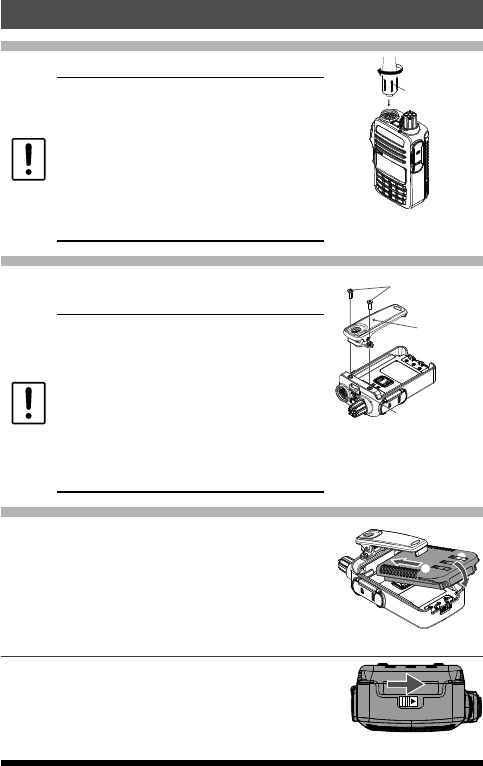
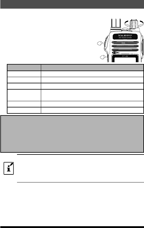
Installing the Antenna
1. Turn the antenna clockwise until it is secured.
zDo not hold or twist the upper part of the
antenna when installing or removing it. To
do so may break the conductors inside the
antenna.
zDo not key the transmit without installing the
antenna. The transmitter components may
be damaged.
zWhen using an antenna other than the
one supplied, or connecting to an external
antenna, ensure that the SWR is adjusted to
1.5 or lower.
Hold the thick base
of the antenna
Attaching the Belt Clip
1. Attach the belt clip on the back of transceiver
using the supplied screws (two).
zBe sure to use the supplied screws when
attaching the belt clip. If any other screws
are used, the belt clip cannot be secured
firmly to the battery pack and the transceiver
may drop off together with the battery pack;
the transceiver and battery pack may fall off,
causing injury, breakage and other damage.
zUse a hand strap which can withstand the
weight of the transceiver. If the hand strap is
not strong enough, the it may break and the
transceiver may fall, causing injury, breakage
and other difficulty.
Supplied Screws
Strap Hole for commercially
available strap
Belt Clip
Installing the Battery Pack
Referring to the figure at the right, insert
the battery pack into the seals of the battery
compartment on the back of the transceiver.
2.
Push the battery pack in until the battery latch
clicks securely.
①
②
Removing the Battery Pack
1. Turn the transceiver OFF. While sliding the latch
in the direction of the arrow, as shown in the
illustration, slide the battery pack downward and
out of the transceiver.
9
FT-4VR/FT-4VE Operating Manual
Supplied Accessories and Options
Supplied Accessories
Rechargeable Li-Ion Battery Pack 7.4V
1,750mAh SBR-28LI
Battery Charger SAD-20B/C/U/G
Rapid Charger SBH-22
Antenna SRA-16N
Belt Clip SHB-18
Operating Manual (this manual)
SBR-28LI Manual
Warranty Card
zEnsure that the name of the dealer from which the transceiver was
purchased, and the date of purchase are indicated on the warranty card.
zIf any item is missing, contact the dealer from which the transceiver was
purchased.
Available Options
Rechargeable Li-Ion Battery Pack 7.4V
1,750mAh SBR-28LI
Battery Charger SAD-20B/C/U/G
Rapid Charger SBH-22
VOX Earpiece Microphone SSM-512B
Antenna SRA-16N
Speaker Microphone SSM-16
B
Programming Cable SCU-35
Clone Cable SCU-36
Belt Clip SHB-18
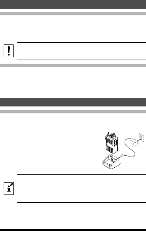
Charging the Battery Pack
Charging the Battery Pack using the Rapid Charger (SBH-22)
Using the supplied AC Adapter (SAD-20B) and the supplied Rapid Charger, it
takes about 3.5 hours* to charge the SBR-28LI battery pack fully.
*: Depending on the battery status, the charging time might be increased.
1. Turn the transceiver OFF to install the battery
pack.
2. Referring to the figure at the right, connect the
battery charger plugs.
When the battery is being charged, rapid
charger cradle indicator lights red.
3. When charging is completed, rapid charger
cradle indicator will light green.
AC Adapter
SAD-20B
Rapid Charger
SBH-22
zThe rapid charger indicator blinks red and the battery pack is not
charged after a lapse of 10 or more hours, stop charging the battery pack
immediately. The battery pack is presumed to be at the end of its service
life, or defective. In this case, replace the battery pack with a new one.
zCharge the battery pack within the temperature range from +5 °C to +35
°C (+41 °F to +95 °F).
10 FT-4VR/FT-4VE Operating Manual
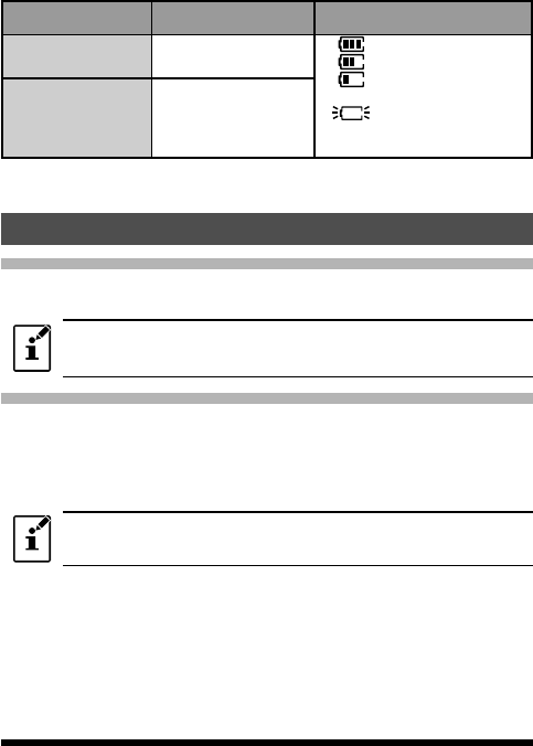
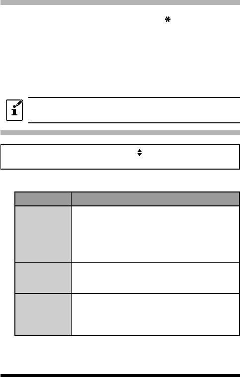
●Approximate Operating Time and Remaining Charge Level
Indication
Approximate operating time for the transceiver with the fully charged lithium-
Ion battery pack (SBR-28LI), and the indication of the remaining charge level
of the battery is shown in the below table:
Frequency band Band in Use Charge Level Indication (Icon)
144 MHz band Approx. 9.0 hours
:Full battery power
:Enough battery power
: Battery is depleted.
Charge battery.
:
(When blinking)
Charge battery
immediately.
FM Broadcast
Band Approx. 12.0 hours
The battery charge level calculations are based on an operating cycle of: Transmitting 6
seconds (5 W): Receiving 6 seconds (VOL Level 16): Stand By 48 seconds (RX SAVE 1:5)
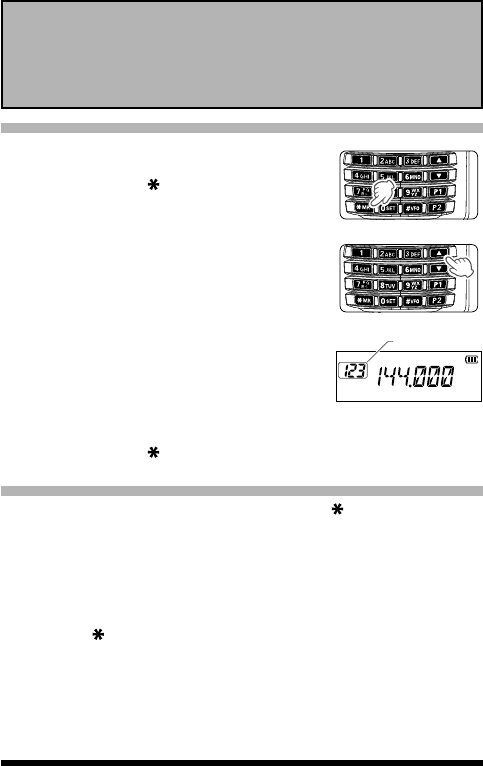
Operation
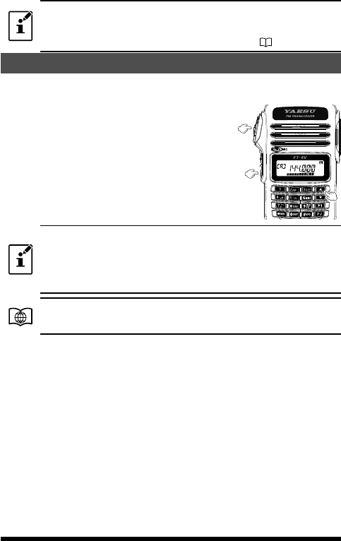
Changing between the VFO-A mode and VFO-B mode
Press the [#VFO] key repeatedly to toggle the frequency control between the
VFO-A mode and VFO-B mode.
To listen to the FM broadcast radio, press the [#VFO] key to change to the
VFO-B. FM broadcast band may be received signals in the VFO-B mode
only.
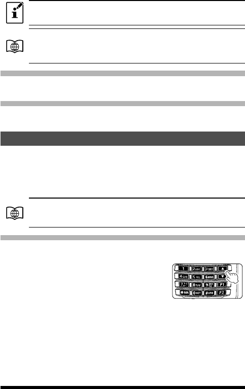
Tuning to a Frequency(Two ways)
●Press the [] key or [] key to tune the frequency.
By pressing the function key and then press the [] key or the [] key,
the frequency will change in 1 MHz steps.
●Press the numeric keys to enter the frequency digits in order, beginning
with the 100 MHz digit.
When entering a frequency using the numeric keys, it may be canceled by
pressing the PTT switch.
11
FT-4VR/FT-4VE Operating Manual
Changing the Frequency Step ("AUTO" for normal operation)
Pressing the [] key or [] key, the frequency step may be changed.
Normally, the factory default setting will provide a good frequency step.
Pressing and holding
the Function key →Pressing the key →Pressing the Function
key
(Entering the Set mode) (Selecting "37 STEP")
1. Press the [] key or the [] key to select the desired frequency step.
2. Press the PTT switch to save the setting and return to normal operation.
In the default setting, of the frequency step is set to “AUTO”, which
automatically provides a suitable frequency step according to the frequency
band.
Adjusting the squelch setting
The squelch level may be adjusted to mute the background noise when no signal is
present.
1. Press the function key and then press the MONI/T-CALL switch.
“LVL □”(0-15) appear on the display.
2. Press the [] key or [] key to a level at which the background noise is
muted.
3. Press the PTT switch to save the setting.
zThe default setting is“LVL 2”.
zWhen the squelch level is increased, the noise is more likely to be
silenced, but it may become more difficult to receive weak signals.
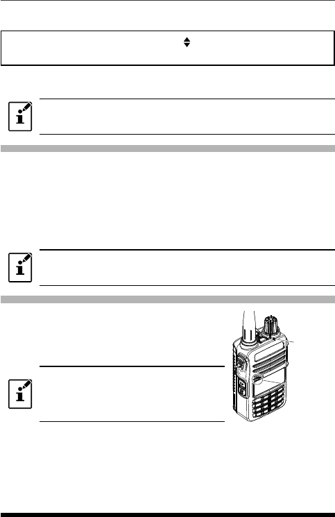
Transmission
1. While pressing and holding the PTT switch,
speak into the microphone.
TX/BUSY indicator lights red during the
transmission.
If the PTT switch is pressed when a frequency
other than the amateur ham radio band is
selected, an alarm tone (beep) will be emitted
and “ERROR” appears on the LCD, disabling
transmission.
2. Release the PTT switch to return to receive
mode.
When receiving a signal, the TX/BUSY Indicator
lights red.
Microphone
TX/BUSY lamp
12 FT-4VR/FT-4VE Operating Manual
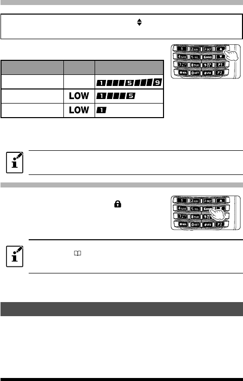
Changing the Transmission Power Level
Pressing and holding
the Function key →Pressing the key →Pressing the
Function key
(Entering the Set mode) (Selecting "40 TX PWR")
1. Press the [] or [] to select one of the following
transmission power levels.
TX PO Level Icon PO meter
HIGH (5W)*(off)
MID (2.5W)
LOW (0.5W)
*
The default setting.
2. Press the PTT switch to save the setting and return to the normal
operation.
The transmission power level may be set separately for each frequency
band.
Locking Keys and PTT switch
1. Press and hold the [6] key, “LOCK” is displayed
on the LCD for one second, the “ ” icon appears
on the LCD, and then the keys and PTT switch
are locked.
zThe keys and the PTT switch may be selected to be locked using Set Mode
[18 LOCK]( 20. The default setting is the [LK KEY] (the keys are
locked).
zThe [MONI/T-CALL] switch and the PWR/VOL knob cannot be locked.
2. Press the [6] (LOCK) switch again, “UNLOCK” will be displayed on the
LCD, the keys and the PTT switch are unlocked.
Tone Calling (1750 Hz)
If your transceiver is FT-4VE (European version), press and hold in the MONI/
T-CALL switch to generates the 1750 Hz burst tone to access the European
repeater.
The transmitter will automatically be activated, and the 1750 Hz audio tone
will be superimposed on the carrier. Once the repeater has been accessed,
release the MONI/T-CALL switch, and use the PTT switch to activate the
transmitter thereafter.
13
FT-4VR/FT-4VE Operating Manual
If needed, the FT-4VR (USA/Asian version), may be set to access repeaters
which require a 1750 Hz burst tone by setting the MONI/T-CALL switch to
serve as a “Tone Call” switch instead. To change the configuration of the
MONI/T-CALL switch, use Set Mode [19 M/T-CL] ( 20).
Using the Memory
The FT-4VR/VE transceiver incorporates Large-capacity memory channels
that can register the operating frequency, communication mode, and other
operational information.
200 Memory Channels
2 Home Channels
10 pairs PMS Memory channel
Each memory channel can store the following information.
Operating frequency Frequency steps TX output power
Memory tag
Repeater information Tone information DCS information
Skip memory information
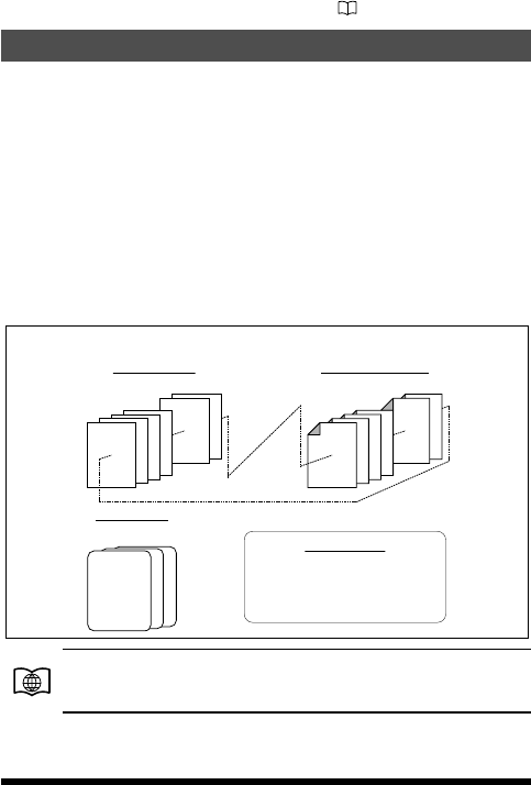
10 Memory Banks, labeled “BANK 1” through “BANK10” Each Memory Bank
can be assigned up to 200 channels from the “standard” and “PMS” memory
channels.
200
199
4
3
2
1
L10/U10
L09/U09
L4/U4
L3/U3
L2/U2
L1/U1
Memory Channel Configuration of the Transceiver
Memory channels
(200 channels)
Home channels
(2 channels)
Memory banks
(10 banks)
Up to 200 memory channels can be
registered to each bank.
(One memory channel can be registered
to several memory banks)
PMS memory channels
(10 sets)
For additional details on the Skip Search Memory, PMS memory
channel and Memory Bank, refer to the Advanced Manual which
may be downloaded from the Yaesu website.
14 FT-4VR/FT-4VE Operating Manual
CAUTIONS!
The information registered to memory channels can be
corrupted by incorrect operation, static electricity, or electrical
noise. Also, it can be erased in the event of a failure or repair. Be
sure to keep a record of the settings on paper.
Registering to Memory Channels
1. Set the frequency and the communication mode
to be registered to a memory channel.
2. Press and hold the [ MR] key.
A blank memory channel will be displayed auto-
matically.
3. Press the [] key or [] key to select the desired
channel number.
4. Input the memory tag
Use the numeric keys to input the characters.
If not inputting a “Tag” (label), proceed to step 5.
Input Character
Example: Press the [2] key repeatedly to
toggle among the following available
characters.
2 → A → B → C → a → b → c → 2 →
Memory Channel
Number
Press the function key to move the cursor.
5. Press and hold the [ MR].
The beep sounds and the memory is saved.
Memory Recall
1. While operating in the VFO mode, press the [ MR] key to enter the
Memory mode.
The memory channel most recently used appears on the LCD.
2. Press the [▲] or [▼] key to select the desired memory channel.
When the transceiver is already set to the Memory mode, an easy way to recall
a memory channel is to enter the memory channel number using the numeric
keypad.
3. Press the [ MR] key to exit the memory mode, and return to the normal
operation.
15
FT-4VR/FT-4VE Operating Manual
Press and hold the MONI/T.CALL key and the PTT switch simultaneously,
while turning the radio ON to enter the preferred operating mode.
In the preferred operating mode, press the [] key or [] key to select the
[
F
5 M-ONLY], then press the function key to enter the Memory Channel
Only mode. To cancel the Memory Channel Only mode, press the [] key
or [] key to select the [
F
5 M-ONLY], then press the function key again.
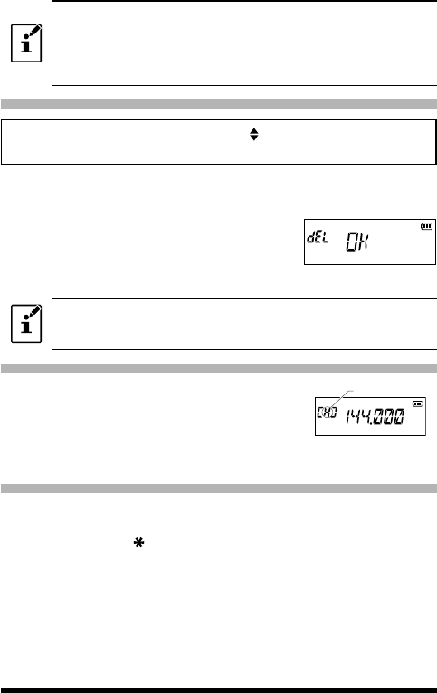
Clearing Memories
Pressing and holding
the Function key →Pressing the key →Pressing the
Function key
(Entering the Set mode) (Selecting "20 MEM DEL")
1. Press the [] key or [] key to select the memory channel from which the
data is to be cleared.
2. Press the function key.
“del OK” appears on the LCD and the memory
channel is cleared.
3. Press the PTT switch to save the setting and
return to the normal operation.
Data on memory channel One, and the Home channel may not be
cleared.
Recalling the Home Channels
1. Press the Function key, and then press the [P1]
key.
“H” and the home channel frequency of the cur-
rently selected band appears on the LCD.
2. Press the Function key, and then press the [P1]
key to return to the previous frequency.
Home channel
indication
Changing the Home Channel Frequency
1. Set the frequency and the operating mode you want to store as a home
channel.
2. Press and hold the [ MR] key.
A blank memory channel will be displayed automatically.
3. Press the [P1] key.
"HOM-IN" is displayed, desired Home channel frequency is changed and re-
turned to normal operation.
16 FT-4VR/FT-4VE Operating Manual
Memory Channel Scanning
The receiver may be set to scan memory channels:
1. While operating in the VFO mode, press the [ MR] key to enter the
Memory mode.
2. Press and hold the [▲] key or [▼] key.
Scanning starts toward higher memory channel numbers.
If the scanner halts on an incoming signal, the back light will turn ON and
the decimal point between the “MHz” and “kHz” digits of the frequency
display will blink. Scanning will resume in about
one second after the other
station signal ceases transmitting
(default setting).
3. Press the PTT switch to cancel the scanning.
If the scan has paused on a signal, rotating the DIAL knob will cause
scanning to resume next memory channel.
Setting the Receive Operation When Scanning Stops
Pressing and holding
the Function key →Pressing the key →Pressing the
Function key
(Entering the Set mode) (Selecting "34 SCN.RSM")
1. Press the [▲] key or [▼] key to select the operation performed after the
scan stops:
Display Description
BUSY(Default
setting)
In BUSY mode, the scanner will halt on a signal it
encounters. Scanning will resume one second after
the other station signal ceases transmitting. In the
case of constant-carrier signals like Weather Station
broadcasts, the scanner will likely remain on this
frequency indefinitely.
HOLD
In HOLD mode, the scanner will halt on a signal it
encounters. Scanning will only resume when it is
manually re-initiated.
TIME
In TIME mode, the scanner will halt on a signal it
encounters, scanning will resume after five seconds
even if a signal is still on the frequency. To cancel
scanning, press the the PTT switch, [▲] or [▼] key.
2. Press the PTT switch to save the setting and exit to normal operation.
17
FT-4VR/FT-4VE Operating Manual
The above setting (Set Mode [34 SCN.RSM]is common for all
scanning operation.
For additional details on the following functions, refer to
the Advanced Manual which may be downloaded from
the Yaesu website.
Using Memory Tag
Memory name tags may be assigned to the memory channels and home
channels.
Using Memory Bank
The transceiver allows using up to 10 memory banks to allow sorting and
registering thechannels in convenient groups.
Scanning Function
The transceiver supports the following four scanning functions:
VFO Scan
Program Scan
Memory Channel Scan
Programmable Memory Scan(PMS)
Memory Bank Scan
For additional details on the Programmable Memory Scan (PMS)
and Memory Bank Scan, refer to the Advanced Manual which
may be downloaded from the Yaesu website.
VFO Scan
VFO scan function scans the frequencies, and detects signals.
1. Press and hold the [] key or the [] to start
scanning in the VFO mode.
2. Press the PTT switch, [▲] or [▼] key to cancel
scanning
.
18 FT-4VR/FT-4VE Operating Manual
zIf the scan has paused on a signal, Turning the transceiver ON will cause
scanning to resume instantly.
zTo set the transceiver action when scanning stops, see “Setting the
Receive Operation When Scanning Stops” on page ] ( 20).
Using Set Mode
The Set Mode permits configuring the various functions according to individual
operating needs and preferences.
1. Press and hold the Function key.
The previously selected Set Mode item is
displayed.
2. Press the [▲] key or [▼] key to select the
desired Set Mode item.
3. Press the function key, then press the [] key or
[] key to change the setting.
4. Press the PTT switch to save the settings and
return to normal operation.
zIn step 4 above, press the Function key to save the new setting and return
to Set Mode item to set the other Set Mode.
zOn some setting screens, key operation is different than described in the
above steps (For example, inputting the characters, etc.). Refer to the
Advance manual.
For additional details, refer to the Advanced Manual which may be
downloaded from the Yaesu website

19
FT-4VR/FT-4VE Operating Manual
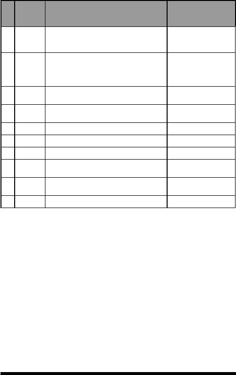
Tables of Set Mode Operations
No. Set Mode
item Description
Selectable options
(Options in bold are the
default settings)
1 APO Sets the length of time until the transceiver
turns off automatically.
OFF / 0.5 Hours
12Hours
2 AR BEP Sets the beep option during ARTS operation. OFF / INRANG /
ALWAYS
3 AR INT Sets the polling interval during ARTS
operation. 25 SEC / 15 SEC
4 BCLO Turns the busy channel lockout function ON/
OFF. BCL.OFF / BCL.ON
5 BEEP Sets the beep function on pressing the
keypad, or stopping the receiver scanning. KEY+SC / KEY / OFF
6 BELL Selects the number of CTCSS/DCS/PAGER/
ARTS Bell ringer repetitions.
OFF / 1 T / 3 T / 5 T / 8
T / CONT
7 CWID Turns the CW Identifier ON/OFF during
ARTS operation. TX OFF / TX ON
8 CW WRT Sets the CW ID during ARTS operation.
ID= (6
characters)
default: blank
9 DC VLT Displays the voltage. (Voltage)
10 DCS.COD Sets the DCS CODE RX and TX. 104 DCS CODEs / OFF
default: 023 R / 023 T
11 DT DLY Sets the DTMF code transmission delay
time.
50MS / 250MS / 450MS
/ 750MS / 1000MS
12 DT SET
Selects the DTMF auto dialer memory
channel and edits the DTMF code (Maximum
16 digits)
d1 d9
13 DT SPD Sets the DTMF code transmission speed. 50MS / 100MS
14 EDG.BEP
Turns the the Band-edge beeper on/off.
while selecting the frequency via the [▲] or
[▼] key.
BEP.OFF / BEP. ON
15 LAMP Selects the LCD/Keypad Lamp mode. 5 SEC / 10 SEC / 30
SEC / CONT / OFF
16 LED.BSY Turns the TX/BUSY lamp ON/OFF while
receiving signals. BSY ON / BSYOFF
17 LED.TX Turns the TX/BUSY lamp ON/OFF while
transmitting signals. TX ON / TXOFF

20 FT-4VR/FT-4VE Operating Manual
No. Set Mode
item Description
Selectable options
(Options in bold are the
default settings)
18 LOCK Configures the lock mode setting. LK KEY / LK PTT / LK
P+K
19 M/T-CL Selects the function of the [MONI/T-CALL]
switch.
MONI / TC1750* /
TC2100 / TC1000 /
TC1450
(*: Eurpean / Asian
Version)
20 MEM.DEL Deletes the memory channel
21 MEM.
TAG Edits the memory channel tag.
22 PAG.ABK Turns the pager answer back Function ON/
OFF ABK.OFF / ABK. ON
23 PAG.CDR Specifies a personal code (receive). 01 05 50, 01 47
50
24 PAG.CDT Specifies a personal code (transmit). 01 05 50, 01 47
50
25 PRI.RVT Turns the Priority Revert feature ON/OFF. RVTOFF / RVT ON
26 PSWD Turns the Password feature ON/OFF. PWD.OFF / PWD. ON
27 PSWDWT Inputs the password. 4 digits
28 RF SQL Adjusts the RF Squelch threshold level.
OFF / S-1 / S-2 / S-3
/ S-4 /S-5 / S-6 / S-8 /
S-FULL
29 RPT.ARS Turns the ARS function on/off. ARS.ON / ARS.OFF
30 RPT.FRQ Sets the repeater shift width.
OFF / 0.05MHz
99.95MHz (
*
)
31 RPT.SFT Sets the repeater shift direction. SIMPLX / +RPT / -RPT
32 RXSAVE Selects the Receivemode Battery Saver
interval (“sleep” ratio) 200 MS 2 SEC / OFF
33 SCN.LMP Turns
the scan lamp ON/OFF while paused.
ON / OFF
34 SCN.RSM Configures the scan stop mode settings. BUSY / HOLD / TIME
35 SKIP Turns the Memory Scan “Skip” channel
selection mode ON/OFF. OFF / SKIP
36 SQL.TYP Selects the Tone Encoder and/or Decoder
mode.
OFF / R-TONE /
T-TONE / TSQL / REV
TN / DCS / PAGER
21
FT-4VR/FT-4VE Operating Manual
No. Set Mode
item Description
Selectable options
(Options in bold are the
default settings)
37 STEP Sets the frequency steps.
AUTO /5.0 / 6.25 / 10.0 /
12.5 / 15.0 / 20.0 / 25.0 /
50.0 / 100.0 k
38 TN FRQ Sets the TONE frequency.
OFF / 67.0 R 100.0 R
254.1 R
OFF / 67.0 T 100.0 T
254.1 T
39 TOT Sets the timeout timer. OFF / 1MIN 3MIN
30MIN
40 TX PWR Selects Transmitter Power HIGH (5W) / MID (2.5W)
/ LOW (0.5W)
41 TX SAVE Turns the Transmitter Battery Saver ON/OFF. SAVOFF / SAV ON
42 VFO.SPL Turns the “VFO Split” operation ON/OFF. VSP.OFF / VSP. ON
43 VOX Turns the VOX function ON/OFF. VOXOFF/ VOX ON
44 WFM.RCV
Broadband FM Radio (WFM) function Enables/
Disables.
WFM.ON / WFM.OFF
45 W/N.DEV Sets the Transmit Modulation Level in the FM
mode. WIDE / NARROW
46 WX ALT Turns the Weather Alert Scan ON/OFF. ALT.OFF / ALT. ON
(*) : This default setting may be displayed, depending on the transceiver
version.
22 FT-4VR/FT-4VE Operating Manual
Restoring to Defaults (Reset) / Setting the Preferred Operating Mode
The following reset or preferred operating modes may be selected.
1. Turn the transceiver OFF.
2. Press and hold the MONI/T.CALL key and the
PTT switch simultaneously, while turning the
transciever ON.
3. When the LCD backlight comes on, release
the MONI/T.CALL key and PTT switch.
4. Referring to the above table, press the [▲] or
[▼] key to select the desired resets or desired
operating modes.
Display Description
F1:SET RST Resets the Set Mode settings to factory defaults.
F2:MEM RST Clears the Memory settings to factory defaults.
F3:MB. RST Clears the Memory Bank assignments.
F4:ALL RST Clears the All memories and other settings to
factory defaults.
F5:M- ONLY Operation on the Memory mode only.
F6:CLONE Clone mode.
CAUTION!
Resetting the transceiver (F2 MEM RST / F4 ALL RST) will clear all
memories.
Please make a note of the memories (memory channel settings,
etc) before resetting.
zTo cancel this operation, turn the transceiver OFF.
zPerform All Reset to restore all of the following Set Mode items to
default.
10 DCS.COD 26 PSWD 27 PSWDWT 30 RPT.FRQ 31 RPT.SFT
35 SKIP 36 SQL.TYP 37 STEP 38 TN FRQ 40 TX PWR
44 W/N.DEV

23
FT-4VR/FT-4VE Operating Manual
Specifications
●General
Frequency Range RX: 136 - 174MHz
TX: 136 - 174 MHz (Asian version)
144 - 146 MHz (European version)
144 - 148 MHz (USA version)
FM Broadcast: 65 - 108 MHz
Channel Steps : 5/10/12.5/15/20/25/50/100kHz
Mode of Emission : F2DF3EF2A
Frequency Stability : ±2.5ppm
(
−
20
°C to +
60
°C [−
4
°F to +
140
°F]
)
Antenna Impedance : 50 ohms
Supply Voltage Nominal: 7.4 V DC, Negative Ground SBR-28LI
Current Consumption :
(Approx.)
190 mA (Receive) 200 mW Output
95 mA (Standby, Saver Off)
23 mA (Standby, Saver On)
5 mA (Auto Power Off)
1.5 A (5 W Tx , 144 MHz) 7.4 V DC
Operating Temperature : –
4
°F to +
140
°F
(
–
20
°C to +
60
°C
)
Case Size : 2.0” (W) x 3.5” (H) x 1.2” (D) (52×90×30mm)
W/O knob and antenna
Weight (Approx.) : 9.17 oz (250g) with SBR-28LI and antenna
●Transmitter
RF Power Output : 5.0 W (High) / 2.5 W (Middle) / 0.5 W (Low)
(@ 7.4 V with SBR-28LI)
Modulation Type : Variable Reactance
Maximum Deviation : ±5.0 kHz
Spurious Emission : USA/Asian version
At least 60 dB below (@TX Power High, Middle)
At least 50 dB below (@TX Power Low)
European version
At least 60 dB below (@TX Power High, Middle)
At least 55 dB below (@TX Power Low)
Microphone Impedance :
(Approx.)
2 k ohms

24 FT-4VR/FT-4VE Operating Manual
●Receiver
Circuit Type : Direct-conversion
Sensitivity : 0.2 μV for 12 dB SINAD (140 - 150 MHz, NFM)
Selectivity (-65 dB/-60 dB) : FM, NFM ±25 kHz / 12.5 kHz
AF Output : 800 mW (16 Ω for THD 10 % 7.4 V DC) internal
speaker
800 mW (16 Ω for THD 10 % 7.4 V DC)
external speaker
Specifications are subject to change without notice, and are guaranteed within the 144 and
amateur bands only. Frequency ranges will vary according to transceiver version; check
with your dealer.

25
FT-4VR/FT-4VE Operating Manual
1. Changes or modifications to this device that are not expressly
approved by YAESU MUSEN could void the user’s authorization to
operate this device.
2. This device complies with part 15 of the FCC Rules. Operation is
subject to the following two conditions: (1) This device may not cause
harmful interference, and (2) this device must accept any interference
including received, interference that may cause undesired operation.
3. The scanning receiver in this equipment is incapable of tuning, or
readily being altered, by the User to operate within the frequency
bands allocated to the Domestic public Cellular Telecommunications
Service in Part 22.
This device complies with Industry Canada license-exempt RSS
standard(s). Operation is subject to the following two conditions: (1) this
device may not cause interference, and (2) this device must accept any
interference, including interference that may cause undesired operation
of the device.
Le présent appareil est conforme aux CNR d’Industrie Canada
applicables aux appareils radio exempts de licence. L’exploitation est
autorisée aux deux conditions suivantes : (1) l’appareil ne doit pas
produire de brouillage, et (2) l’utilisateur de l’appareil doit accepter tout
brouillage radioélectrique subi, même si le brouillage est susceptible d’en
compromettre le fonctionnement.
DECLARATION BY MANUFACTURER
The Scanner receiver is not a digital scanner and is incapable of being
converted or modified to a digital scanner receiver by any user.
WARNING: MODIFICATION OF THIS DEVICE TO RECEIVE
CELLULAR RADIOTELEPHONE SERVICE SIGNALS IS PROHIBITED
UNDER FCC RULES AND FEDERAL LAW.

Copyright 2018
YAESU MUSEN CO., LTD.
All rights reserved.
No portion of this manual may be
reproduced without the permission of
YAESU MUSEN CO., LTD.
YAESU MUSEN CO., LTD.
Tennozu Parkside Building
2-5-8 Higashi-Shinagawa, Shinagawa-ku, Tokyo
140-0002 Japan
YAESU USA
6125 Phyllis Drive, Cypress, CA 90630, U.S.A.
YAESU UK
Unit 12, Sun Valley Business Park, Winnall Close
Winchester, Hampshire, SO23 0LB, U.K.
Printed in Japan