Yaesu Musen 20695X20 FM DUAL BAND TRANSCEIVER User Manual Operating Manual 1
Yaesu Musen Co., Ltd. FM DUAL BAND TRANSCEIVER Operating Manual 1
Contents
- 1. Operating-Manual-1
- 2. Operating-Manual-2
Operating-Manual-1
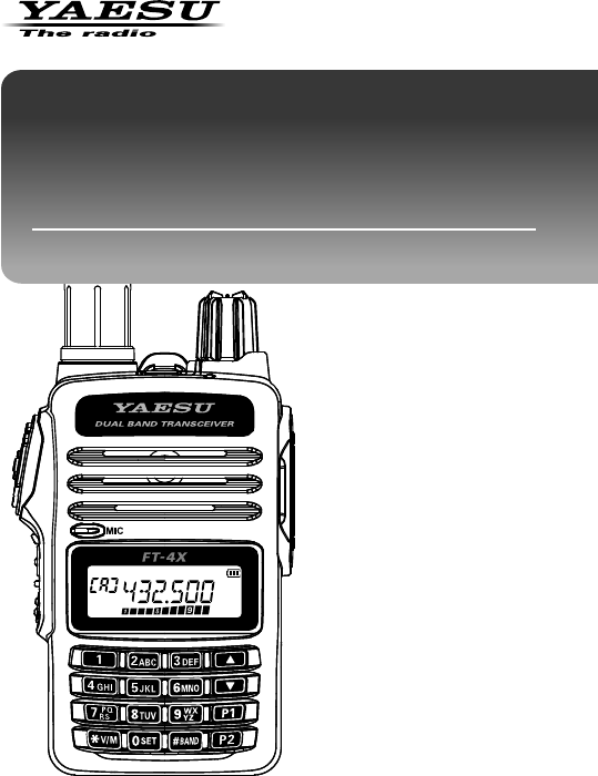
FM 144/430MHz
DUAL BAND TRANSCEIVER
Operating Manual
FT- 4X R
FT- 4XE

Contents ................................................ 2
About this manual ................................ 2
Introduction ........................................... 1
Quick Guide .......................................... 2
Controls & Connections ...................... 3
Transceiver ............................................ 3
Display ................................................... 5
The Keypad Functions ........................... 7
Preparation ............................................ 8
Installing the Antenna ............................ 8
Attaching the Belt Clip ........................... 8
Installing the Battery Pack .................... 8
Removing the Battery Pack ............. 8
Supplied Accessories and Options .... 9
Supplied Accessories ............................ 9
Available Options ................................... 9
Charging the Battery Pack ................... 9
Charging the Battery Pack using the
Rapid Charger (SBH-22) ....................... 9
Operation ............................................. 10
Changing between VFO mode and
Memory mode ...................................... 10
Selecting the Operating Band ............. 10
Tuning to a Frequency(Two ways) ...... 10
Changing the Frequency Step ("AUTO"
for normal operation) ...................... 11
Adjusting the squelch setting .............. 11
Transmission ........................................ 12
Changing the Transmission Power Level
................................................................12
Locking Keys and PTT switch ............. 13
Tone Calling (1750 Hz) ....................... 13
Using the Memory .............................. 14
Registering to Memory Channels ....... 15
Memory Recall ..................................... 15
Clearing Memories .............................. 16
Recalling the Home Channels ............ 16
Changing the Home Channel Frequency
................................................................16
Memory Channel Scanning ................. 17
Setting the Receive Operation When
Scanning Stops .................................... 17
Using Memory Tag .............................. 18
Using Memory Bank ............................ 18
Scanning Function ............................. 18
VFO Scan ............................................. 18
Using Set Mode ................................... 19
Tables of Set Mode Operations .......... 19
Restoring to Defaults (Reset) / Setting
the Preferred Operating Mode ........... 23
Specifications ..................................... 24
Contents
About this manual
Reference icon symbols and conventions are used in this manual. Their
meanings are described in the below chart.
Symbols Description
This icon indicates cautions and information that should be read.
This icon indicates notes, tips and information that should be read.
This icon indicates other pages containing relevant information.
This icon indicates FT-4X Advance Manual on the YAESU Website
containing relevant information.

1
FT-4XR/FT-4XE Operating Manual
Introduction
Thank you for purchasing this Yaesu product.
•FT-4XR/4XE is a handheld transceiver for operation in the 144 MHz and
430 MHz Amateur radio bands.
•Bridged Transless (BTL) amplifier provides One Full Watt of Audio in spite
of small size.
•Two Quick Recall Keys (User Programmable) for Individual Preferences
•Lockout Capabilities for Keypad/PTT Lockout.
•Emergency Operation (Alarm and HOME channel display)equipped.
r A variety of individual selective calling functions; such as tone squelch
(CTCSS) and DCS functions ........................................................... 20
r Large-capacity 200 memory channels ........................................... 14
r
3 home channels and 10 pairs of PMS memory channels ..................... 16
r
Create mnemonic tags for memory channels and Home channel .. 18
r Automatic power off (APO) feature turns the transceiver OFF after a
preset time period ........................................................................... 19
r
The cloning feature allows the memory and configuration data from one
transceiver to be transferred to another FT-4XR/4XE. .................... 23
r
The VOX system provides automatic transmit/receive switching based on
voice ................................................................................................ 19
We urge you to read this manual in its entirety, and also the Advance Manual
(available for download on the Yaesu website), to gain a full understanding of
the amazing capability of the exciting new FT-4XR/FT-4XE Transceiver.
2FT-4XR/FT-4XE Operating Manual
① Turning the Power ON
Rotate the until it clicks.
② Adjusting the volume
Rotate the .
③ Selecting the Operating Band
Press the .
The operating frequency changes between
the 144 MHz Band, the 430 MHz Band,
and the FM Radio Broadcast Band.
④ Tuning the frequency
Press the or .
⑤ Adjusting the squelch setting
The squelch level may be adjusted to mute
the background noise when no signal is
Quick Guide
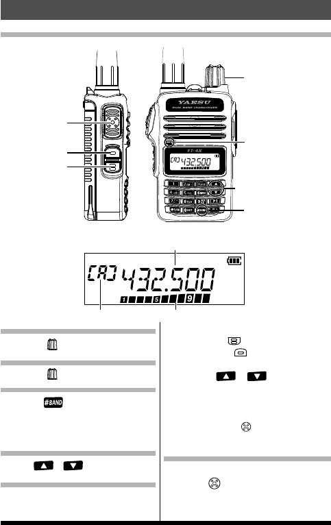
Names and display of Controls
PTT Switch
MONI/T-CALL
Switch
PWR/VOL Knob
[BAND] Key
Microphone
(Frequency up and down) Key
Function Key
S Meter / PO MeterVFO-A Mode
Operating Frequency
Normal operation
(
VFO Mode
)
received.
1. Press the (Function key), then
press the (MONI/T-CALL
switch).
2. Press the or to adjust the
squelch level.
* When the squelch level is increased, the noise is
more likely to be silenced, but it may become more
difficult to receive weak signals.
3. Press the PTT ( ) switch to save the
setting.
⑥ Transmitting Signals
zTransmitting
Press the , then speak into microphone.
3
FT-4XR/FT-4XE Operating Manual
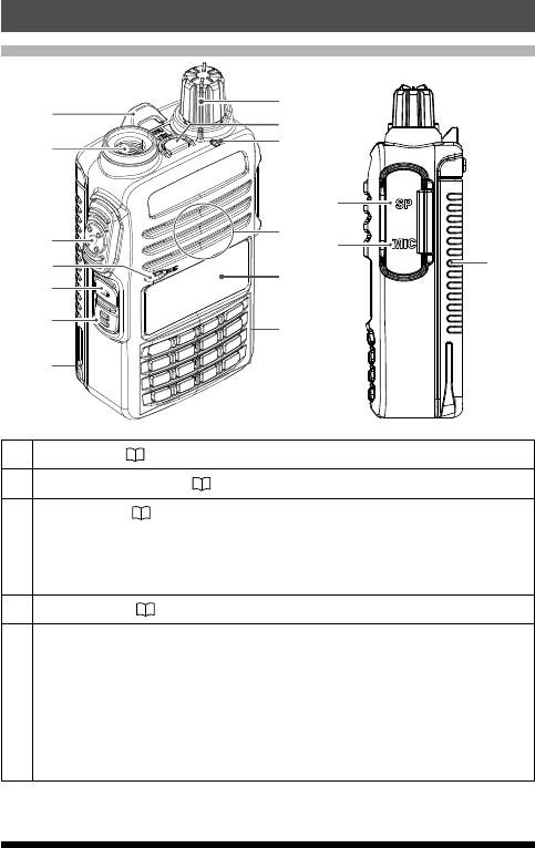
Controls & Connections
Transceiver
①
②
③
④
⑤
⑥
⑦
⑧
⑨
⑪
⑫
⑬
⑭
⑮
⑩
⑦
①Strap Hole (8)
②Antenna Jack(SMA) (8)
③
PTT Switch ( 11)
•Press and hold the PTT switch to transmit, and release it to receive.
•In the Set mode, press the PTT switch to save the new setting and
return to normal operation.
④Microphone ( 11)
⑤
MONI/T.CALL Switch
•USA/Asian version
While pressing and holding the MONI/T.CALL Switch, the squelch is
opened temporarily. Press the Function key, then press the MONI/
T.CALL Switch to adjust the squelch level.
•European version
Press the MONI/T.CALL switch to activates the T-CALL(1750 Hz).
4FT-4XR/FT-4XE Operating Manual
⑥
Function Key (19)
Pressing the Function key activates the “Secondary” key function.
Pressing and holding the Function key enters the Set mode.
In the Set mode, pressing the Function key to determine the setting
⑦Battery pack(9)
⑧
PWR/VOL Knob
• Turn this control clockwise to turn the transceiver ON and to increase
the volume.
•Counter-clockwise rotation into the click-stop will turn the transceiver
OFF.
⑨Emergency Key
Press and hold it for three seconds to enable the Emergency Alarm
beep functions and display the Home channel frequecy (VHF).
⑩TX/BUSY Indicator Lamp
This indicator glows green when the squelch opens, and it glows red
during transmit.
⑪Speaker
⑫LCD (Liquid Crystal Display)
The display shows frequecny and current operating condition.
⑬Keypad
The functions of the keypad are described in detail on page 5.
⑭SP jack
SP jack provides connection for an microphone.
⑮MIC jack
MIC jack provides connection for microphone and clone cable.
5
FT-4XR/FT-4XE Operating Manual
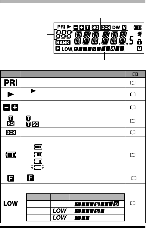
Display
S Meter:
Displays the received signal strength
PO Meter:
Displays the transmit power level
Frequency / Memory Tag / PAGER
Set Mode Item
VFO-A/B
Memery Channel Number
Home Channel Display
Memory Bank
Icon Description
Priority Memory Channel 14
:
Memory channel registered as a skip
memory 14
Repeater Shift Direction
Semi duplex Memory (a simultaneously) 18
:
Appears when the tone encoder function.
:
Appears when the tone squelch function. 21
Appears when the DCS function. 20
The battery condition is displayed in 4 steps.
:
Full battery power
:
Enough battery power
:
Battery is depleted. Charge battery.
:
(When blinking) Charge battery immediately.
10
: Appears when a function key is pressed. 7
TX Power Level Indicator (LOW/MID TX Power Selected)
Tx Power Icon TX Power Meter during transmission
HIGH (5 W)
(No display)
MID (2 W)
LOW (0.5 W)
12
6FT-4XR/FT-4XE Operating Manual
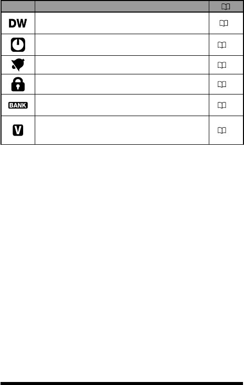
Icon Description
Appears when the Dual Receive(DW) function is
enabled. 7
Appears when the APO (Automatic Power-Off)
function is enabled. 19
Appears when the bell function is enabled. 19
Appears when the lock function is enabled. 13
Appears when the Memory Bank function is
enabled. 18
Appears when the VOX (Voice Operated Transmit)
function is enabled. 22

7
FT-4XR/FT-4XE Operating Manual
The Keypad Functions
Key
Primary Function (Press Key)
Secondary
Function
(Press F +
Key)
Third
Function
(Press and
Hold for over
one second)
VFO Memory Recall
Inputting
Memory Tag
Function
Activates the “Sec-
ondary” key func-
tion( appears)
Activates the “Secondary”
key function( appears)
Moves the cursor to the
left.
Deactivates the
“Secondary” key
function( appears)
Enters the Set mode.
#BAND
Switches the band
control between
VHF, UHF and FM
RADIO Broadcast
Memory Offset Tuning -PMS(Program Mem-
ory (Mode) Scan)
Program Scan
Setting
V/M
Switches the
frequency control
between the VFO
and Memory Sys-
tems
-
Numbers“*”、“+”、“-”、
“/”、“@”
Press and hold this key
to complete the memory
channel registration
Dual Receive (DW)
function Memory write mode
P1
Recalls the stored
P1(Programmble
key) setting
-Stores to the Home
channel
Recalls the Home
channel
Stores the
P1(Programmble key)
setting
P2
Recalls the stored
P2(Programmble key)
setting
-Stores the Semi -Duplex
transmit frequency
Reverses the
transmit and receive
frequencies while
working through a
repeater
Stores the
P2(Programmble key)
setting
1Number “1” Recalls the stored memory
channel Number “1” -
Recalls the “Weather”
broadcast channel bank
2
ABC
Number “2” Recalls the stored memory
channel
Number “2”, or
characters “A”, “B”, or
“C”
-
Activates the ARTS
feature
3
DEF
Number “3” Recalls the stored memory
channel
Number “3”, or
characters “D”, “E”, or
“F”
- -
4
GHI
Number “4” Recalls the stored memory
channel
Number “4”, characters
“G”, “H”, or “I” - -
5
JKL
Number “5” Recalls the stored memory
channel
Number “5”, characters
“J”, “K”, or “L” - -
6
MNO
Number “6” Recalls the stored memory
channel
Number “6”, or
characters “M”, “N”,or
“O”
-
Key Lock feature
7
PQRS
Number “7” Recalls the stored memory
channel
Number “7”, or characters
“P”, “Q”, “R”, or
“S”
- -
8
TUV
Number “8” Recalls the stored memory
channel
Number “8”, or
characters“T”, “U”, or
“V”
- -
9
WXYZ
Number “9” Recalls the stored memory
channel
Number “9”, or characters
“W”, “X”, “Y”,
or “Z”
DTMF autodialer
settting -
0
SET
Number “0” Recalls the stored memory
channel Number “0” - -
8FT-4XR/FT-4XE Operating Manual
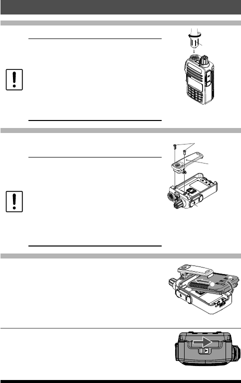
Preparation
Installing the Antenna
1. Turn the antenna clockwise until it is secured.
zDo not hold or twist the upper part of the
antenna when installing or removing it. To
do so may break the conductors inside the
antenna.
zDo not key the transmit without installing the
antenna. The transmitter components may
be damaged.
zWhen using an antenna other than the
one supplied, or connecting to an external
antenna, ensure that the SWR is adjusted to
1.5 or lower.
Hold the thick base
of the antenna
Attaching the Belt Clip
1. Attach the belt clip on the back of transceiver
using the supplied screws (two).
zBe sure to use the supplied screws when
attaching the belt clip. If any other screws
are used, the belt clip cannot be secured
firmly to the battery pack and the transceiver
may drop off together with the battery pack;
the transceiver and battery pack may fall off,
causing injury, breakage and other damage.
zUse a hand strap which can withstand the
weight of the transceiver. If the hand strap is
not strong enough, the it may break and the
transceiver may fall, causing injury, breakage
and other difficulty.
Supplied Screws
Strap Hole for commercially
available strap
Belt Clip
Installing the Battery Pack
1. ①Referring to the figure at the right, insert
the battery pack into the seals of the battery
compartment on the back of the transceiver.
2.
②Push the battery pack in until the battery latch
clicks securely.
①
②
Removing the Battery Pack
1. Turn the transceiver OFF. While sliding the latch
in the direction of the arrow, as shown in the
illustration, slide the battery pack downward and
out of the transceiver.