Yaesu Musen 30043X30 25 Watts VHF/ FM Marine Transceiver User Manual C DATA GX2360S GX2360S p65
Yaesu Musen Co., Ltd. 25 Watts VHF/ FM Marine Transceiver C DATA GX2360S GX2360S p65
UserManual.wiki
>
Yaesu Musen
>
30043X30 User Manual
OPERATING MANUAL
Navigation menu
Upload a User Manual
Namespaces
Wiki Guide
HTML
PDF
Info
Views
User Manual
Discussion / Help
Navigation
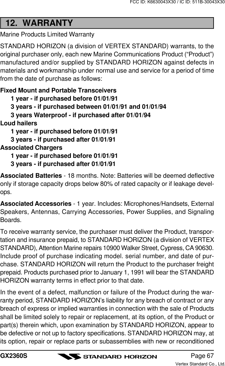
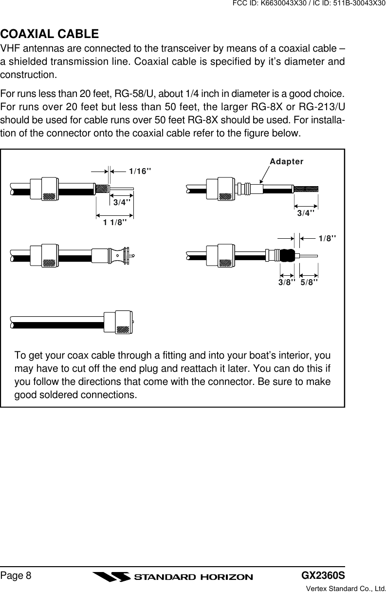
![Page 1GX2360SQUANTUM GX2360S25 Watt VHF/FMMarine TransceiverOwner's ManuallHuge alphanumeric LCD, knobs and keyslLarge 2.8 inch internal loudspeaker producing louder audiol30 W Loud Hailer with listen back and 4 fog horns, Bells & WhistleslRemovable ClearVoice speaker microphone with 16/9 key and channelselectionlDisplay shows channel names, and repeats GPS information]lCapable of connecting 2 optional RAM+ second station remote micro-phoneslDSC distress call automatically broadcasts lat/long and vessel ID]lDSC position request function and NMEA data input/output to connect toGPS Plotter]lVersatile user-programmable Scanning, Priority Scan and Dual WatchlNOAA Weather channels and AlertlOne-button access to Channel 16 and 9lOne-button access to user selectable preset channelslAccess to all US, Canadian and International channels]with GPS attachedFCC ID: K6630043X30 / IC ID: 511B-30043X30Vertex Standard Co., Ltd.](https://usermanual.wiki/Yaesu-Musen/30043X30/User-Guide-366783-Page-1.png)
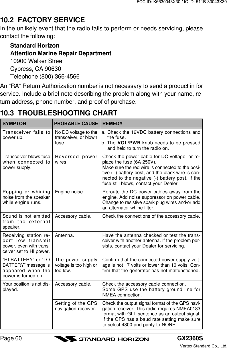
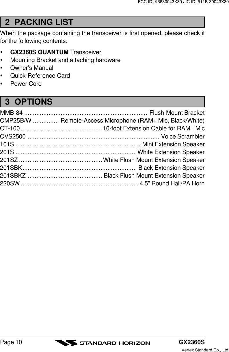
![Page 9GX2360S1 GENERAL INFORMATION1.1 INTRODUCTIONThe STANDARD HORIZON QUANTUM is a VHF/FM transceiver designed foruse in the frequency range of 156.025 to 163.275 MHz. The QUANTUM can beoperated from 11 to 16 VDC and has a switchable RF output power of 1 watt or25 watts.The QUANTUM is capable of RTCM SC101 DSC (Digital Selective Calling)operation and second station operation with the use of the improved optionalRAM+ mic (CMP25 remote-control speaker/microphone with display).The QUANTUM operates on all currently-allocated marine channels which areswitchable for use with USA, International, or Canadian regulations. It has anemergency channel 16 which can be immediately selected from any channelby pressing the red [16/9] key. NOAA Weather channels can also be accessedimmediately by pressing the [WX] key with channel selection.Other features of the transceiver include: scanning, priority scanning, submers-ible speaker mic, high and low voltage warning, and GPS repeatability.1.2 FCC / INDUSTRY CANADA INFORMATIONThe following data pertaining to the transceiver is necessary to fill out the li-cense application.Type Acceptance ....................................................................... FCC Part 80Output Power .............................................. 1 Watt (low) and 25 Watts (high)Emission .......................................................................16K0G3E, 16K0G2BFrequency Range ....................................................156.025 to 163.275 MHzFCC Type Number ................................................................. K6630043X30Industry Canada Type Approval ............................................511B-30043X30FCC ID: K6630043X30 / IC ID: 511B-30043X30Vertex Standard Co., Ltd.](https://usermanual.wiki/Yaesu-Musen/30043X30/User-Guide-366783-Page-9.png)
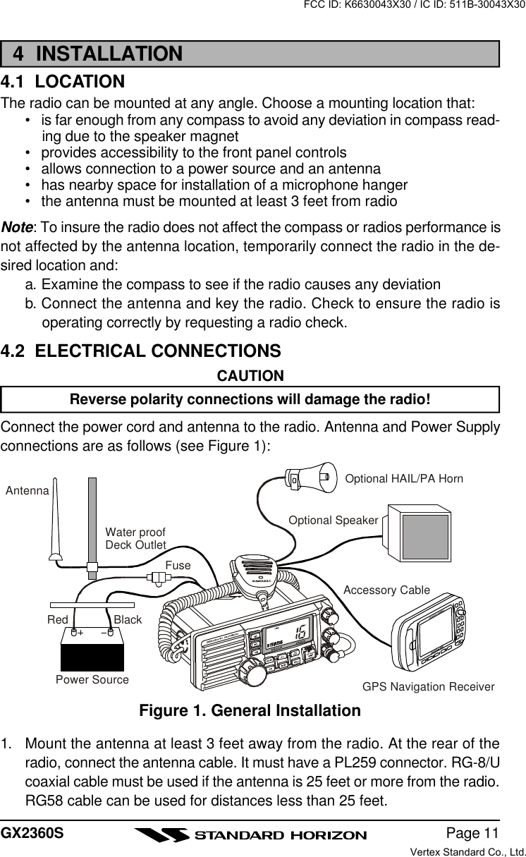
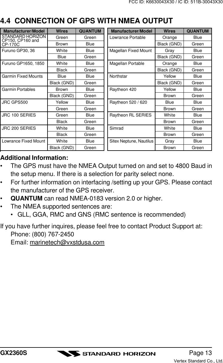
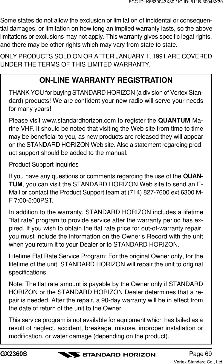
![GX2360SPage 144.5 CHECKING GPS CONNECTIONSAfter connections have been made between the QUANTUM and the GPS, asmall satellite icon will appear on the top right corner of the LCD display. To seeadditional GPS information press and hold the [H/L(NAV)] key until theQUANTUM shows the Date, Time, SOG and COG.4.6 CHANGING THE GPS TIMEFrom the Factory the QUANTUM shows GPS satellite time or UTC time. A timeoffset is needed to offset this time to show the local time in your area.1. Press and hold down the [CALL/SET(MENU)] key until “RADIO SETUP”menu appears.2. Press the [CALL/SET(MENU)] key, then select“TIME SET” with the CHANNEL selector knob.3. Press the [CALL/SET(MENU)] key.4. Turn the CHANNEL selector knob to select time off-set from UTC. See illustration below to find your off-set time from UTC. If “0:00” is assigned, the time isthe same as UTC (Universal Time Coordinated orGMT Greenwich Mean Time).5. Press the [CALL/SET(MENU)] key to store the timeoffset.6. Press the [16/9] key or turn the CHANNEL selector knob to select “EXIT,”then press the [CALL/SET(MENU)] key to return to the “RADIO SETUP”menu, select “EXIT” and press the [CALL/SET(MENU)] key to return toradio operation.OFFSET TIME TABLEFCC ID: K6630043X30 / IC ID: 511B-30043X30Vertex Standard Co., Ltd.](https://usermanual.wiki/Yaesu-Musen/30043X30/User-Guide-366783-Page-14.png)
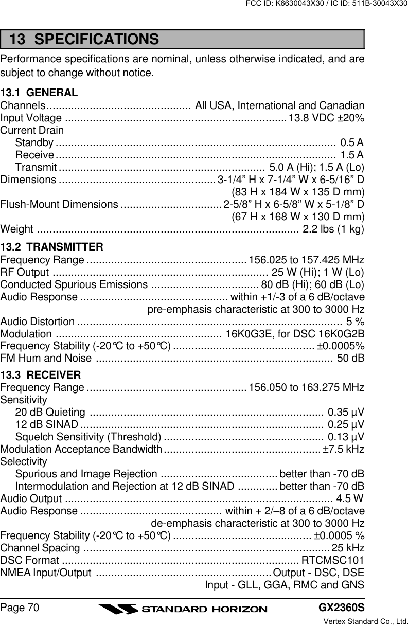
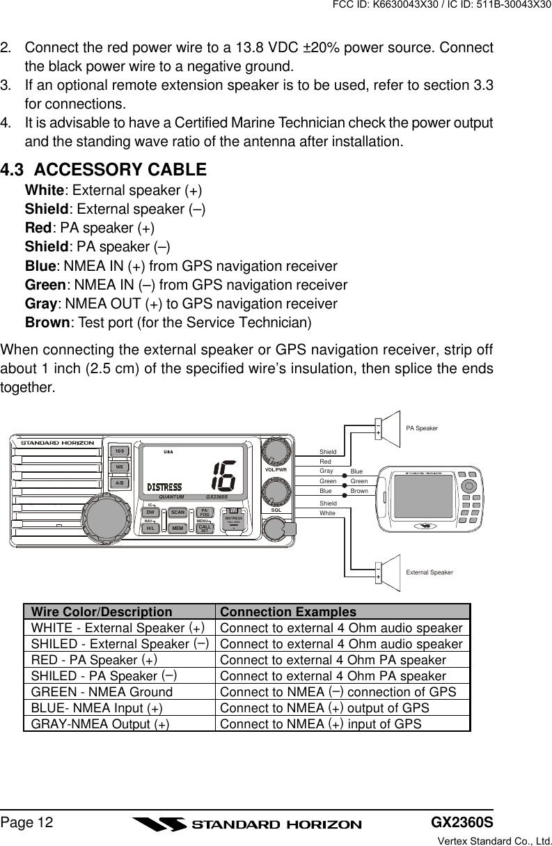
![Page 15GX2360S4.7 CHANGING COG TO TRUE OR MAGNETICAllows customizing the NAV data showing GPS Course Over Ground (COG).Factory default is True however following the steps below the COG can bechanged to Magnetic.1. Press and hold down the [CALL/SET(MENU)] keyuntil “RADIO SETUP” menu appears.2. Press the [CALL/SET(MENU)] key, then select“TRUE MAG” in the “RADIO SETUP” menu with theCHANNEL selector knob.3. Press the [CALL/SET(MENU)] key.4. Turn the CHANNEL selector knob to select “MAG-NETIC” or “TRUE.”5. Press the [CALL/SET(MENU)] key to store the se-lected setting.6. Turn the CHANNEL selector knob to select “EXIT,”then press the [CALL/SET(MENU)] key to return to the “RADIO SETUP”menu, select “EXIT” and press the [CALL/SET(MENU)] key to return toradio operation.FCC ID: K6630043X30 / IC ID: 511B-30043X30Vertex Standard Co., Ltd.](https://usermanual.wiki/Yaesu-Musen/30043X30/User-Guide-366783-Page-15.png)
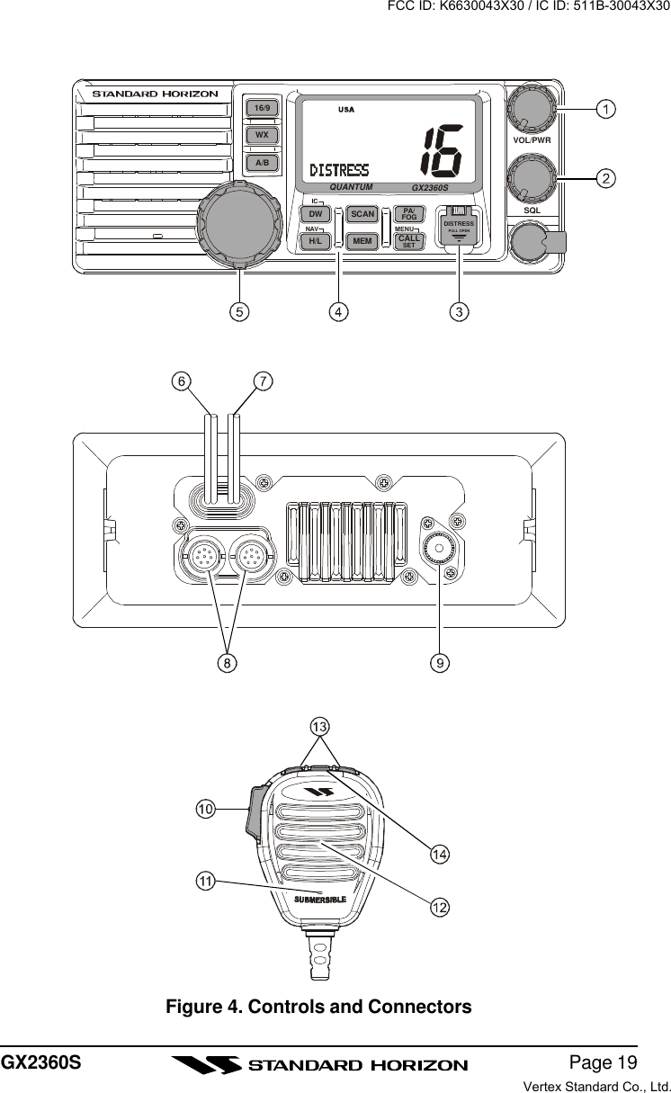
![GX2360SPage 185 CONTROLS AND INDICATORSNOTEThis section defines each control of the transceiver. See Figure 4 forlocation of controls. For detailed operating instructions refer to chapter 6of this manual.5.1 CONTROLS AND CONNECTIONSPOWER SWITCH/VOLUME CONTROL (VOL/PWR)Turns the transceiver on and off as well as adjusts the audio volume. Toturn the transceiver on press and hold this knob until the LCD turns on. Toturn it off, press and hold this knob until the LCD turns off. When the poweris turned on, the transceiver is set to the last selected channel.Secondary UseWhen the transceiver is turned on while the [SCAN] and [WX] keys are helddown, the internal microprocessor is reset. This clears the memory and alluser-programmed settings, such as scan memory, and priority scan as-signments. This condition is known as the default condition, the same aswhen shipped from the factory. For a list of these defaults, see the section6.18 Resetting the Transceiver’s Microprocessor.NOTEResetting the microprocess will not erase the DSC MMSI and theIndividual Directory Call information.SQUELCH CONTROL (SQL)Adjusting this control clockwise, sets the point at which random noise onthe channel does not activate the audio circuits but a received signal does.This point is called the squelch threshold. Further adjustment of the squelchcontrol will degrade reception of wanted transmissions.[DISTRESS] KeyUsed to send a DSC Distress Call. To send the distress call refer to section7.5.1 (Transmitting A DSC Distress Call).KEYPAD[16/9] KeyImmediately recalls channel 16 from any channel location. Holding downthis key recalls channel 9. Pressing the [16/9] key again reverts to theprevious selected working channel.Secondary usePress and hold the [16/9] key then press the [WX] key to switch betweenUSA, International and Canadian bands.FCC ID: K6630043X30 / IC ID: 511B-30043X30Vertex Standard Co., Ltd.](https://usermanual.wiki/Yaesu-Musen/30043X30/User-Guide-366783-Page-18.png)
![GX2360SPage 20[WX] KeyImmediately recalls the previously selected NOAA weather channel fromany channel.Secondary use1. Holding down the [16/9] key while pressing the [WX] key changes themode from USA to International or Canadian.2. Holding down the [WX] and [SCAN] key while turning the power onresets the microprocessor and erases scan channels from memory.This clears the memory and establishes the factory-set defaults. Fora list of these defaults, see the section on 6.19 Resetting theTransceiver’s Microprocessor.[A/B] KeyImmediately recalls two user assigned channels from any channel.[DW(IC)] KeyScans for voice communications on CH16 and another selected channeluntil a signal is received on either channel. (Dual watch)NOTE: When the DSC SCANNING feature is enabled (see section 7.2DSC SCAN), the radio watches for a transmission on CH16, anotherselected channel, and CH70 until a signal is received (Triple watch).Secondary usePress and hold [DW(IC)] key, when the optional RAM+ Mic is connected,intercom operation will operate between radio and RAM+ Mic.[H/L(NAV)] KeyToggles between 25 W (High) and 1 W (Low) power. When the [H/L(NAV)]key is pressed while the transceiver is on channel 13 or 67, the powerwill temporarily switch from LO to HI power until the PTT is released. The[H/L(NAV)] key does not function on transmit inhibited and low poweronly channels.Secondary usePress and hold [H/L(NAV)] key, the LCD displays NAV GPS Data, Time,SOG (Speed Over Ground), and COG (Course Over Ground) when aGPS is connected to the accessory cable of the QUANTUM. See sec-tion 4.4 CONNECTION OF GPS WITH NMEA OUTPUT.[SCAN] Key1. Starts and stops scanning of programmed channels.2. If held while the [UP(p)] or [DOWN(q)] key on the microphone arepressed or CHANNEL selector knob on radio is turned, the radio willshow the channels programmed in scan memory. This function willnot work if the unit is scanning.FCC ID: K6630043X30 / IC ID: 511B-30043X30Vertex Standard Co., Ltd.](https://usermanual.wiki/Yaesu-Musen/30043X30/User-Guide-366783-Page-20.png)
![Page 21GX2360SNOTE: The priority channel is channel 16 only.3. Pressing and holding again will delete the channel from scan memory.[MEM] KeyMemorizes the selected channel into the transceivers scan memory forscanning. When pressed again, it DELETES the channel from the scanmemory.Secondary usePress and hold [MEM] key to lock out the front panel keys and CHAN-NEL selector konb. Press and hold [MEM] key again, unlock the frontpanel keys (except [16/9] and [DISTRESS] keys) and CHANNEL selec-tor konb.[PA/FOG] KeyAvailable to operate the PA dfunction or the FOG HORN function.[CALL/SET(MENU)] KeyThe [CALL/SET(MENU)] key functions as the enter key.Secondary usePress the [CALL/SET(MENU)] key to access the DSC OPERATIONmenu. The “INDIVIDUAL CALL,” “GROUP CALL,” “ALL SHIPS CALL,”“POSITION REQUEST,” “POSITION SEND,” “STANDBY MODE,” and“CALL WAITING” functions can be accessed from the DSC OPERA-TION menu.Press and hold the [CALL/SET(MENU)] key to access the RADIO SETUPor DSC SETUP menu. The following functions can be accessed in themenu (refer to Section7).RADIO SETUP-menu DSC SETUP-menuFCC ID: K6630043X30 / IC ID: 511B-30043X30Vertex Standard Co., Ltd.](https://usermanual.wiki/Yaesu-Musen/30043X30/User-Guide-366783-Page-21.png)
![GX2360SPage 22CHANNEL SELECTOR KNOBRotary knob used to select channels and to choose menu items (such asthe DSC menu, radio setup and DSC setup menu). The [UP(p)] /[DOWN(q)] key on the microphone can also be used to select channelsand menu items.Secondary UseŸWhile holding down the [SCAN] key and turning the CHANNEL selectorknob, you can confirm memory channels for scanning.ŸAdjust the audio output level while in the PA/FOG mode.ACCESSORY CONNECTION CABLEConnects the QUANTUM to a GPS, and an external speaker. See section3 OPTIONS for a list of speakers STANDARD HORIZON offers.DC INPUT CABLEConnects the radio to a DC power supply capable of delivering 12V DC.RAM MIC CONNECTORSConnects the QUANTUM to the enhanced RAM+ MIC (Remote AccessMicrophone). Refer to section 9 RAM+ MIC OPERATION.ANTENNA JACKConnects an antenna to the transceiver. Use a marine VHF antenna withan impedance of 50 ohms.PTT (Push-To-Talk) SWITCHKeys the transmitter when the transceiver is in radio mode. If the transceiveris in the intercom operation mode (between the RAM+ and the QUANTUM),it activates the QUANTUM microphone for voice communications.MICROPHONETransmits the voice message with reduction of background noise.MICROPHONE SPEAKERThe same audio heard through internal radio speaker is heard through mi-crophone speaker.[UP(p)] / [DOWN(q)] KEYSThe [UP(p)] and [DOWN(q)] on the microphone function the same as theCHANNEL selector knob on the front panel of the transceiver.[16/9] KeyPressing the [16/9] key immediately recalls channel 16 from any location.Press and hold the [16/9] key to recall channel 9. Pressing the [16/9] keyagain will revert the radio to the previous selected channel.FCC ID: K6630043X30 / IC ID: 511B-30043X30Vertex Standard Co., Ltd.](https://usermanual.wiki/Yaesu-Musen/30043X30/User-Guide-366783-Page-22.png)
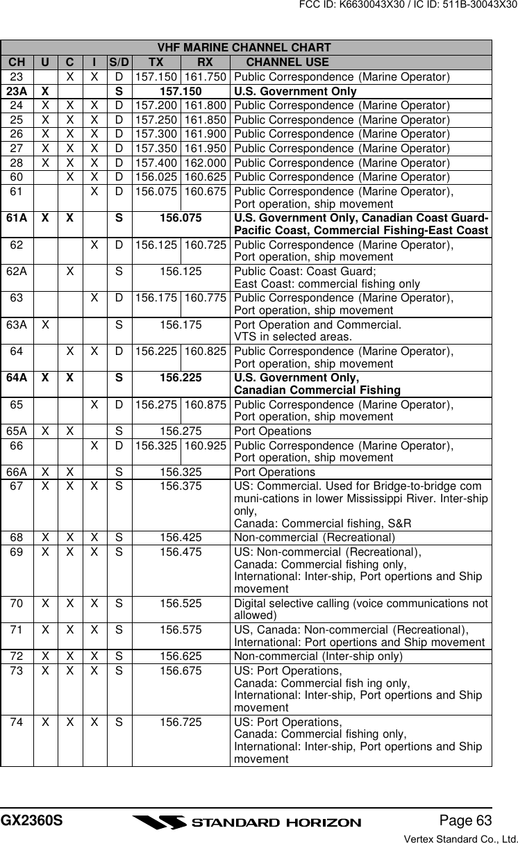
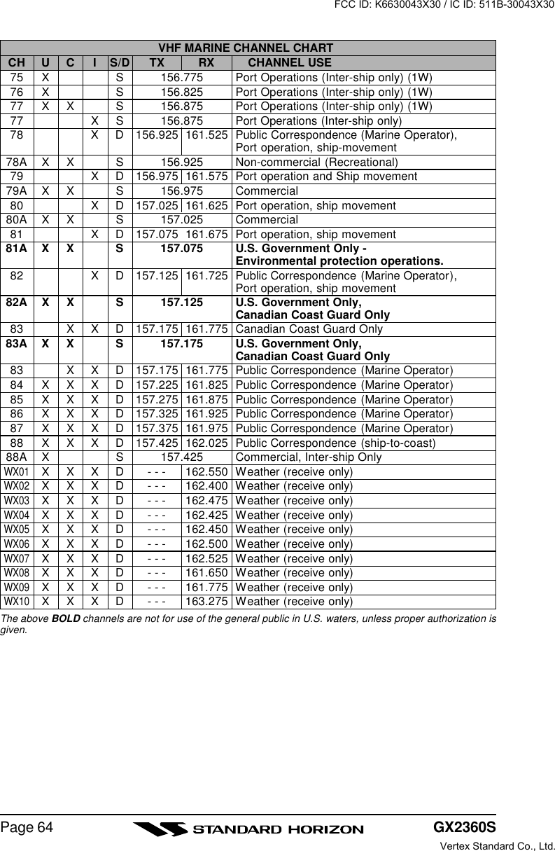
![GX2360SPage 246.4 SIMPLEX/DUPLEX CHANNEL USERefer to the VHF MARINE CHANNEL CHART (page 63) for instructions on useof simplex and duplex channels.NOTEAll channels are factory-programmed in accordance with FCC (USA),Industry Canada (Canada), and International regulations. Mode of op-eration cannot be altered from simplex to duplex or vice-versa.6.5 USA, CANADA, AND INTERNATIONAL MODE1. To change the modes, hold the [16/9] key and press the [WX] key. Themode changes from USA to International to Canadian with each press ofthe [WX] key.2. “USA” will be displayed on the LCD for USA mode, “INTL” will be displayedfor International mode, and “CAN” will be displayed for Canadian mode.3. Refer to the VHF MARINE CHANNEL CHART (page 63) for allocated chan-nels in each mode.6.6 NOAA WEATHER CHANNELS1. To receive a NOAA weather channel, press the [WX] key from any channel.The transceiver will go to the last selected weather channel.2. Turn the CHANNEL selector knob on the radio or [UP(p)] / [DOWN(q)]keys on the microphone to select a different NOAA weather channel.3. To exit from the NOAA weather channels, press the [WX] key. The trans-ceiver returns to the channel it was on prior to a weather channel.6.7 NOAA WEATHER ALERTIn the event of extreme weather disturbances, such as storms and hurricanes,the NOAA (National Oceanic and Atmospheric Administration) sends a weatheralert accompanied by a 1050 Hz tone and subsequent weather report on one ofthe NOAA weather channels. When the Weather Alert feature is enabled (seesection 8.5 WX ALERT), the transceiver is capable of receiving this alert if thefollowing is performed:1. Program NOAA weather channels into the transceiver’s memory for scan-ning. Follow the same procedure as for regular channels under section6.15.2. Press the [SCAN] key once to start memory scanning or hold down the[SCAN] key during memory scanning to start priority scanning.3. The programmed NOAA weather channels will be scanned along with theregular-programmed channels. However, scanning will not stop on a nor-mal weather broadcast unless a NOAA alert is received.FCC ID: K6630043X30 / IC ID: 511B-30043X30Vertex Standard Co., Ltd.](https://usermanual.wiki/Yaesu-Musen/30043X30/User-Guide-366783-Page-24.png)
![Page 25GX2360S4. When an alert is received on a NOAA weather channel, scanning will stop andthe transceiver will emit a loud beep to alert the user of a NOAA broadcast.5. Press the [WX] key to stop the alert tone and receive the weather report.NOTEIf the [WX] key is not pressed the alert tone will be emitted for 5 minutesand then the weather report will be received.NOTEThe Weather Alert feature is also engaged while the transceiver is re-ceiving on one of the NOAA weather channels.6.8 NOAA WEATHER ALERT TESTINGIn the event of a major storm or other appreciable weather condition requiringvessels at sea or other bodies of water to be notified, the NOAA (National Oceano-graphic and Atmospheric Administration) broadcasts a 1050 Hz tone that somemarine VHF radios can detect. (Refer to Section 6.7 “NOAA WEATER ALERT”on how to use this feature.) This tone, when detected, will produce a loud beepfrom the radio speaker to signal that a weather alert is being broadcast.In order to test this system, the NOAA broadcasts the 1050 Hz tone everyWednesday, sometime between 11 AM and 1 PM.6.9 EMERGENCY (CHANNEL 16 USE)Channel 16 is known as the Hail and Distress Channel. An emergency may bedefined as a threat to life or property. In such instances, be sure the transceiveris on and set to CHANNEL 16. Then use the following procedure:1. Press the microphone push-to-talk switch and say “Mayday, Mayday, May-day. This is , , ” (your vessel’s name).2. Then repeat once: “Mayday, ” (your vessel’s name).3. Now report your position in latitude/longitude, or by giving a true or mag-netic bearing (state which) to a well-known landmark such as a navigationaid or geographic feature such as an island or harbor entry.4. Explain the nature of your distress (sinking, collision, aground, fire, heartattack, life-threatening injury, etc.).5. State the kind of assistance your desire (pumps, medical aid, etc.).6. Report the number of persons aboard and condition of any injured.7. Estimate the present seaworthiness and condition of your vessel.8. Give your vessel’s description: length, design (power or sail), color andother distinguishing marks. The total transmission should not exceed 1minute.FCC ID: K6630043X30 / IC ID: 511B-30043X30Vertex Standard Co., Ltd.](https://usermanual.wiki/Yaesu-Musen/30043X30/User-Guide-366783-Page-25.png)
![Page 27GX2360S6.11 MAKING TELEPHONE CALLSTo make a radiotelephone call, use a channel designated for this purpose, Thefastest way to learn which channels are used for radiotelephone traffic is to askat a local marina. Channels available for such traffic are designated PublicCorrespondence channels on the channel charts in this manual. Some ex-amples for USA use are Channels 24, 25, 26, 27, 28, 84, 85, 86, and 87. Callthe marine operator and identify yourself by your vessel’s name, The marineoperator will then ask you how you will pay for the call (telephone credit card,collect, etc.) and then link your radio transmission to the telephone lines.The marine telephone company managing the VHF channel you are using maycharge a link-up fee in addition to the cost of the call.6.12 OPERATING ON CHANNELS 13 AND 67Channel 13 is used at docks and bridges and by vessels maneuvering in port.Messages on this channel must concern navigation only, such as meeting andpassing in restricted waters.Channel 67 is used for navigational traffic between vessels.By regulation, power is normally limited to 1 Watt on these channels. Your radiois programmed to automatically reduce power to this limit on these channels.However, in certain situations it may be necessary to temporarily use a higherpower. See page 20 (H/L key) for means to temporarily override the low-powerlimit on these two channels.6.13 PROHIBITED COMMUNICATIONSThe FCC prohibits the following communications:•False distress or emergency messages:•Messages to “any boat” except in emergencies and radio tests;•Messages to or from a vessel on land;•Transmission while on land;•Obscene, indecent, or profane language (potential fine of $10,000).6.14 DUAL WATCH (TO CH16)1. Adjust the SQL knob until the background noise disappears.2. Select the channel you wish to dual watch to CH16.3. Press the [DW(IC)] key. The display will scan between CH16 and the chan-nel that was selected in step 2.If a transmission is received on the channel selectedin step 2, the QUANTUM will dual watch to CH16.4. To stop Dual Watch press the [DW(IC)] key again.FCC ID: K6630043X30 / IC ID: 511B-30043X30Vertex Standard Co., Ltd.](https://usermanual.wiki/Yaesu-Musen/30043X30/User-Guide-366783-Page-27.png)
![GX2360SPage 283. To stop scanning, press the [SCAN], [16/9], [WX],[CALL/SET(MENU)], or PTT key.NOTETriple watch (T/W) means the radio is watching CH70 for DSC Calls.Dual watch (D/W) means the radio is not watching CH70 for DSC Calls.6.15 MEMORY SCANNING (M-SCAN)NOTEDuring scanning, the dot matrix area of the LCD will show “M-SCAN” or“P-SCAN” depending on the scan mode selected.1. Adjust the SQL knob until background noise disappears.2. Select a desired channel to be scanned using theCHANNEL selector knob. Press and hold the[SCAN] key, “MEM” will appear on the LCD whichindicates the channel has been programmed intothe transceivers memory.3. Repeat step 2 for all the desired channels to be scanned.4. To DELETE a channel from the transceiver’s memory, select the channelthen press and hold the [SCAN] key, “MEM” will disappear in the LCD.5. To start scanning, press the [SCAN] key. Scanningwill proceed from the lowest to the highest pro-grammed channel number and will stop on a chan-nel when a transmission is received.6. The channel number will blink during reception.7. To stop scanning, press the [SCAN], [16/9], [WX], [CALL/SET(MENU)], orPTT key.6.16 PRIORITY SCANNING (P-SCAN)1. Channel 16 is set as the priority channel and cannot be changed.2. To select priority scanning, press the [SCAN] key tostart memory scanning (“M-SCAN” will appears),then press and hold down the [SCAN] key until “P-SCAN” appears on the LCD. Scanning will proceedbetween the memorized channels and the priority channel. CH 16 the prior-ity channel will be scanned after each programmed channel.MEM CH. CH. 16 CH. 70øMEM CH. CH. 16 CH. 70øFCC ID: K6630043X30 / IC ID: 511B-30043X30Vertex Standard Co., Ltd.](https://usermanual.wiki/Yaesu-Musen/30043X30/User-Guide-366783-Page-28.png)
![Page 29GX2360S6.17 CHANNEL A /B INSTANT CALLTwo calling channels (used by an organization or a favorite channel) can bepreset. But USA channels 9 and 16, and WX channels should not be assignedas A or B channels because they are readily available with the [16/9] and [WX]keys. If the [A/B] key is pressed and no channel A or B has been assigned, thealert signal will be present.6.17.1 Storing new channel A/B1. Press and hold down the [A/B] key and rotate the CHANNEL Selector knobto select the desired channel.2. Release the [A/B] key to store a desired channel as channel A/B.3. Repeat steps to program second channel A/B.6.17.2 Changing the stored channel A/B1. Press the [A/B] key for memorized channel to appear.2. Press and hold down the [A/B] key and rotate the Channel Selector knob toselect the desired channel.3. Release the [A/B] key to store a desired channel as channel A/B.NOTEThe stored channels will delete in microprocessor resetting mode only.6.17.3 Operating the channel A/BPressing the [A/B] key more than once toggles betweenchannel A, channel B and the channel that was receivedon.6.18 PA/FOG OPERATIONPA HAIL mode:PA HAIL mode allows the transceiver to be used as a power hailer when anoptional 4 ohm HAIL/PA speaker is installed. The Hail mode has a listen-backfeature which provides two way communication through the HAIL/PA speaker.FOG HORN mode:Automatic signaling is transmitted through the HAIL/PA speaker.6.18.1 Operating the PA HAIL mode1. Press the [PA/FOG] key, then select “PA” with theCHANNEL selector knob.2. Press the [CALL(MENU)] key.3. Press the PTT switch to speak through theFCC ID: K6630043X30 / IC ID: 511B-30043X30Vertex Standard Co., Ltd.](https://usermanual.wiki/Yaesu-Musen/30043X30/User-Guide-366783-Page-29.png)
![GX2360SPage 30HAIL/PAspeaker.Rotate the CHANNEL selector knob to control theAF output level. The AF output level can be set from0 to 30 watts.4. To exit the PA HAIL mode, press the [16/9], [WX] or [CALL/SET(MENU)]key.6.18.2 Operating the FOG HORN modeOperator can select from FOG 1, FOG 2, FOG 3, FOG 4, HORN, SIREN,AGROUND, or ANCHOR.FOG 1: POWER BOAT UNDERWAYFOG 2: POWER BOAT STOPPEDFOG 3: SAIL BOAT, FISH VESSEL, TOW VESSELFOG 4: VESSEL UNDER TOW1. Press the [PA/FOG] key, then select “FOG” with theCHANNEL selector knob.2. Press the [CALL/SET(MENU)] key.3. Turn the CHANNEL selector knob to select the func-tion.4. Press the [CALL/SET(MENU)] key.5.On the HORM and SIREN modes, press the PTTswitch to activate the tone through the HAIL/PAspeaker.Rotate the CHANNEL selector knob to control theAF output level. The AF output level can be set from0 to 30 watts.6. To exit the FOG HORN mode, press the [16/9], [WX]or [CALL/SET(MENU)] key.6.19 KEYPAD LOCKINGTo oder to prevent accidental frequency change, front panel keys (except [DIS-TRESS], [16/9] and [CALL/SET(MENU)] key) and CHANNEL selector knobmay be locked out.Press and hold [MEM] key to lock out the front panelkeys and CHANNEL selector konb. Press and hold[MEM] key again, unlock the front panel keys and CHAN-NEL selector konb.FCC ID: K6630043X30 / IC ID: 511B-30043X30Vertex Standard Co., Ltd.](https://usermanual.wiki/Yaesu-Musen/30043X30/User-Guide-366783-Page-30.png)
![Page 31GX2360S6.20 NAVIGATION INDICATIONThe transceiver has the ability to display the time, SOG and COG date, as wellas the vessel’s position (LAT/LON), when connected to a GPS receiver.1. Press and hold the [H/L(NAV)] key to display posi-tion information. If the GPS receiver is not receivinga fix, the display will be as shown in the illustrationon the right.2. To hide the position information, press the[H/L(NAV)] key.6.21 INTERCOM OPERATIONIf the RAM+ Mic is connected to the QUANTUM, you may communicate be-tween the QUANTUM and RAM+ Mic, or RAM+ Mic and RAM+ Mic (See page57 for Intercom Operation of the RAM+ Mic).6.22.1 Communication1. Press and hold the [DW(IC)] key while in the “RA-DIO” mode, the mode is changed to “INTERCOM”mode.2. If your QUANTUM is equipped two RAM+ Mic, se-lect the companion you wish to communicate (RAM1,RAM2, or ALL) with the CHANNEL selector knob,then press the [CALL/SET(MENU)] key to termi-nated.2. When the “INTERCOM” operation isactivated, “INTERCOM” is displayedon the QUANTUM, and “IC” is dis-played on the RAM+ Mic.3. Press the PTT switch. The “TALK” isdisplayed.NOTE: A warning beep is emittedwhen the QUANTUM microphone’sPTT switch is pressed while the RAM+Mic’s PTT switch is pressed.4. Speak slowly and clearly into the microphone, hold the microphone about1/2 inch away from your mouth.5. When finished, release the PTT switch.6. Press and hold the [DW(IC)] key again the mode will revert to “RADIO”mode.(RAM+ Mic’s PTT switch is pressed)(MATRIX’s PTT switch is pressed)FCC ID: K6630043X30 / IC ID: 511B-30043X30Vertex Standard Co., Ltd.](https://usermanual.wiki/Yaesu-Musen/30043X30/User-Guide-366783-Page-31.png)
![GX2360SPage 326.22.2 CallingHold down the [DW(IC)] key for 1 second or more, when the “INTERCOM”operation is activated. A calling beep is emitted twice from the transceiverspeaker.NOTEDisable any operation of the QUANTUM, whencommunicate the both RAM+ Mic while “INTER-COM” mode.6.22 VOICE SCRAMBLERIf privacy of communications is desired, a CVS2500 voice scrambler (VS) canbe installed in the transceiver. Contact your Dealer to have a CVS2500 installed.Refer to the section 8.9 VOICE SCRAMBLER to program the voice scrambler.1. Turn on the transceiver.2. Select a channel that was programmed for scram-bler mode (“VS” will appear on the LCD).ŸIf a channel is not set for the voice scrambler, thedisplay will be as shown in the illustration at theright (“VS” will disappear from the LCD).ŸIf a voice scrambler is canceled temporarily in the“SETUP” menu, the display will be as shown inthe illustration at the right.3. Monitor the channel before transmitting.4. Transmit the voice message. The signal sent will bescrambled.6.23 RESETTING THE TRANSCEIVER’S MICROPROCESSORResetting the microprocessor restores the initial, factory supplied conditions inthe transceiver. These are called the default conditions.To reset the microprocessor, first turn the transceiver off. Then while pressingthe [WX] and [SCAN] keys, turn the transceiver on. The default conditions are:ŸNo channels in the SCAN memory.ŸChannel 16 will be selected when the transceiver is turned on.ŸWX channel 01 will be recalled when the [WX] key is pressed.ŸKey beep will be on.NOTEResetting the microprocessor will not erase DSC MMSI and DirectoryCall Waiting information.FCC ID: K6630043X30 / IC ID: 511B-30043X30Vertex Standard Co., Ltd.](https://usermanual.wiki/Yaesu-Musen/30043X30/User-Guide-366783-Page-32.png)
![Page 33GX2360S7 DIGITAL SELECTIVE CALLING7.1 GENERALWARNINGThis radio is designed to generate a digital maritime distress and safetycall to facilitate search and rescue. To be effective as a safety device,this equipment must be used only within communication range of a shore-based VHF marine channel 70 distress and safety watch system. Therange of signal may vary but under normal conditions should be approxi-mately 20 nautical miles.Digital Selective Calling is a semi-automated method of establishing a radiocall, it has been designated by the International Maritime Organization (IMO)as an international standard for establishing VHF, MF and HF radio calls. It hasalso been designated as part of the Global Maritime Distress and Safety Sys-tem (GMDSS). It is planned that DSC will eventually replace aural watches ondistress frequencies and will be used to announce routine and urgent maritimesafety information broadcasts.This new system allows mariners to instantly send a distress call with GPSposition (when connected to the transceiver) to the US Coast Guard and othervessels within range of the transmission. DSC will also allow mariners to initiateor receive Distress, Urgency, Safety, Routine, POSITION REQUEST, POSI-TION SEND, and Group calls to or from another vessel equipped with a DSCtransceiver.7.2 DSC SCANWhen the radio is shipped from the factory it is programmed so CH70 (the DSCchannel) is scanned at all times. A selection is provided in the SETUP MENU todisable the DSC SCAN. Turning off DSC SCAN will disable the radio from re-ceiving DSC calls (i.e.: Distress Call, Individual Call, All Ships Call, and PositionRequests). If you want to use any of the functions the selection must be left ON.To Change DSC SCAN Method:1. Press and hold down the [CALL/SET(MENU)] keyuntil “RADIO SETUP” menu appears.2. Turn the CHANNEL selector knob to select “DSCSETUP” menu.3. Press the [CALL/SET(MENU)] key, then select “DSCSCAN” with the CHANNEL selector knob.4. Press the [CALL/SET(MENU)] key.FCC ID: K6630043X30 / IC ID: 511B-30043X30Vertex Standard Co., Ltd.](https://usermanual.wiki/Yaesu-Musen/30043X30/User-Guide-366783-Page-33.png)
![GX2360SPage 345. Turn the CHANNEL selector knob to select “ON”or“OFF.”6. Press the [CALL/SET(MENU)] key to store the se-lected setting.7. To exit this menu and return to radio operation modepress the [16/9] key.7.3 USCG DSC WATCHThe USCG has plans to upgrade its VHF National Distress System (expectedby 2005), so at the time of printing only larger vessels that are required to carryVHF DSC radios will be able to hear your distress transmission.7.3.1 Maritime Mobile Service Identity (MMSI)What is an MMSI?An MMSI is a nine digit number used on Marine Transceivers capable of usingDigital Selective Calling (DSC). This number is used like a telephone number toselectively call other vessels.THIS NUMBER MUST BE PROGRAMMED INTO THE RADIO TO OPERATETHE MATRIX DSC FUCTIONS.How can I obtain an MMSI assignment?Boat US offers free MMSI numbers. Visit the following to register:http://www.boatus.com/mmsi/.7.3.2 Programming the MMSINOTEUser MMSI can be input only twice. If the user tries to input MMSI morethan twice, the radio will show the display on the right. If the user needsto change the MMSI more than twice, the transceiver will have to be sentto Factory Service. Refer to the section 10.2 FACTORY SERVICE.1. Press and hold down the [CALL/SET(MENU)] keyuntil the “RADIO SETUP” menu appears.2. Turn the CHANNEL selector knob to the left to se-lect “DSC SETUP” menu.3. Press the [CALL/SET(MENU)] key, then select“USER MMSI” with the CHANNEL selector knob.4. Press the [CALL/SET(MENU)] key. The “UserMMSI” number will appear, and the first space willflash.FCC ID: K6630043X30 / IC ID: 511B-30043X30Vertex Standard Co., Ltd.](https://usermanual.wiki/Yaesu-Musen/30043X30/User-Guide-366783-Page-34.png)
![Page 35GX2360S5. Select first number of your MMSI, then press the[CALL/SET(MENU)] key to step to the next number.6. Repeat step 5 to set your MMSI (up to nine digits).7. When finished programming the number, press andhold the [CALL/SET(MENU)] key to store the num-ber in memory.8. To exit this menu and return to radio operation modepress the [16/9] key.7.4 ADDITIONAL DIGITAL SELECTIVE CALLING INFORMATIONFor additional information the USCG has an excellent site that should be visitedat www.navcen.uscg.mil/marcoms/gmdss/dsc.html.7.5 DSC DISTRESS CALLThe QUANTUM is capable of transmitting and receiving DSC Distress mes-sages to all DSC radios. The QUANTUM may be connected to a GPS to alsotransmit the Latitude, Longitude of the vessel.7.5.1 Transmitting A DSC Distress CallNOTETo be able to transmit a DSC distress call a MMSI number must beprogrammed, refer to section 7.3.2 Programming the MMSIIn order for your ships location to be transmitted a GPS must be connected tothe QUANTUM, refer to section 4.4 CONNECTION OF GPS WITH NMEA OUT-PUT1. Lift the red spring loaded DISTRESS cover andpress the [DISTRESS] key. The “DISTRESS” menuwill appear on the LCD.2. Press and hold the [DISTRESS] key. The radios dis-play will count down (3-2-1) and then transmit theDistress call.3. When the distress signal is sent, CH70 and “TX”icon will appear on the LCD. After the message hasbeen sent, the radio will sound a Distress Alarm.4. The transceiver “shadow-watches” for a transmis-sion between CH16 and CH70 until an acknowledg-ment signal is received. “DISTRESS” and “WAIT-ING” will appear on the LCD.5. If an acknowledgement is received, select channel16 and advise your distress situation.FCC ID: K6630043X30 / IC ID: 511B-30043X30Vertex Standard Co., Ltd.](https://usermanual.wiki/Yaesu-Musen/30043X30/User-Guide-366783-Page-35.png)
![GX2360SPage 366. If no acknowledgment is received, the distress callis repeated in 4 minute intervals until an acknowl-edgment is received.7. When a DSC Distress acknowledgment is received,a distress alarm sounds and channel 16 is automatically selected. The LCDshows the MMSI of the ship responding to your distress.RECEIVED ACK: acknowledgment signal is received.RECEIVED RLY: relay signal is received from another vessel or coast sta-tion.8. To cancel the DSC distress alarm signal from the speaker, press any key.Cancel a DSC Distress CallIf a DSC Distress call was sent by error the QUANTUM allows you to send amessage to other vessels to cancel the Distress Call that was made in error.Press the [CALL/SET(MENU)] key, turn the CHANNEL selector knob to select“CANCEL.” Then, press the [CALL/SET(MENU)] key or turn off the radio.7.5.2 Receiving a DSC Distress Call1. A distress call is received. An emergency alarmsounds.Then channel 16 is automatically selected.2. Press any key to stop the alarm.3. Turn the CHANNEL selector knob to change the dis-play to show the position of the vessel in distress.4If the position of the vessel distress data does notinclude position, the LCD will show the display onthe left.NOTEYou must continue monitoring channel 16 as a coast station may requireassistance in the rescue attempt.FCC ID: K6630043X30 / IC ID: 511B-30043X30Vertex Standard Co., Ltd.](https://usermanual.wiki/Yaesu-Musen/30043X30/User-Guide-366783-Page-36.png)
![Page 37GX2360S7.6 ALL SHIPS CALLThe All Ships Call function allows contact to be established with other vesselstations without having their ID in the individual calling directory. Also, priorityfor the call can be designated as Urgency or Safety.URGENCY Call: This type of call is used when a vessel may not truly be indistress, but have a potential problem that may lead to a dis-tress situation. This call is the same as saying PAN PAN PANon channel 16.SAFETY Call: Used to transmit boating safety information to other vessels.This message usually contains information about an overdueboat, debris in the water. Loss of a navigation aid or an impor-tant meteorological message. This call is the same as sayingSecurite” Securite” Securite’.7.6.1 Transmitting an All Ships Call1. Press the [CALL/SET(MENU)] key. The “DSC OP-ERATION” menu will appear.2. Turn the CHANNEL selector knob to select “ALLSHIPS.”3. Press the [CALL/SET(MENU)] key. (To cancel, turnthe CHANNEL selector knob to select “EXIT.”)5. Turn the CHANNEL selector knob to select the na-ture of call (“URGENCY” or “SAFETY”).6. Press the [CALL/SET(MENU)] key to transmit theselected type of all ships DSC call.7. After the ALL SHIPS CALL is transmitted, the trans-ceiver will switch to CH16.8. Listen to the channel to make sure it is not busy,then key the microphone and say PAN PAN PAN orSecurite” Securite” Securite depending on the prior-ity of the call. Then announce your call sign and an-nounce the channel you wish to switch to for com-munications.FCC ID: K6630043X30 / IC ID: 511B-30043X30Vertex Standard Co., Ltd.](https://usermanual.wiki/Yaesu-Musen/30043X30/User-Guide-366783-Page-37.png)
![GX2360SPage 387.6.2 Receiving an All Ships Call1. When an all ships call is received, an emergencyalarm sounds.The radio will automatically change to channel 16.2. Press any key to stop the alarm.3. Turn the CHANNEL selector knob to see the MMSIof the vessel transmitting the All Ships Call.4. Monitor channel 16 or traffic channel until the UR-GENCY voice communication is completed.7.7 INDIVIDUAL CALLThis feature allows the QUANTUM to contact another vessel with a DSC VHFradio and automatically switch the receiving radio to a desired communicationschannel. This feature is similar to calling a vessel on CH16 and requesting togo to another channel (switching to the channel is private between the twostations).7.7.1 Setting up the Individual / Position Call DirectoryThe QUANTUM has a DSC directory that allows you to store a vessel or per-son names and the MMSI number associated with vessels you wish to transmitIndividual calls, Position Requests and Position Send transmissions.To transmit an Individual call you must program this directory with informationof the persons you wish to call, similar to a cellular phones telephone directory.1. Press and hold down the [CALL/SET(MENU)] keyuntil “RADIO SETUP” menu appears.2. Turn the CHANNEL selector knob to select “DSCSETUP” menu.3. Press the [CALL/SET(MENU)] key, then select“INDIV DIR” with the CHANNEL selector knob.4. Press the [CALL/SET(MENU)] key, then select“ADD” with the CHANNEL selector knob.5. Press the [CALL/SET(MENU)] key.6. Turn the CHANNEL selector knob to scroll throughthe first letter of the name of the vessel or personyou want to reference in the directory.7. Press the [CALL/SET(MENU)] key to store the firstletter in the name and step to the next letter to theright.8. Repeat step 6 and 7 until the name is complete. The name can consist ofup to eleven characters, if you do not use all eleven characters press theFCC ID: K6630043X30 / IC ID: 511B-30043X30Vertex Standard Co., Ltd.](https://usermanual.wiki/Yaesu-Musen/30043X30/User-Guide-366783-Page-38.png)
![Page 39GX2360S[CALL/SET(MENU)] key to move to the next space.This method can also be used to enter a blank spacein the name. To clear the previous letter, press the[H/L(NAV)] key.9. After the eleventh letter or space has been entered, press the [CALL/SET(MENU)] key to advance to the MMSI (Maritime Mobile Service Iden-tity Number) number entry.10. Turn the CHANNEL selector knob to scroll through numbers, 0-9. To enterthe desired number and move one space to the right press the[CALL/SET(MENU)] key. Repeat this procedure until all nine space of theMMSI number are entered.11. If a mistake was made entering in the name or the MMSI number repeatpressing the [CALL/SET(MENU)] key until the wrong character is selected,then move the channel knob to correct the entry.12. To store the data entered, press and holdthe [CALL/SET(MENU)] key.13. To enter another individual address, repeat steps 4through 13.14. To exit this menu and return to radio operation mode press the [16/9] key.NOTESelecting “NEXT” or “EXIT” will automatically save the name and MMSInumber into memory.7.7.2 Setting up Individual ReplyAllows setting up the radio to automatically (default setting) or manually re-spond to a DSC Individual call requesting you to switch to a working channel forvoice communications. When Manual is selected the MMSI of the calling ves-sel is shown allowing you to see who is calling. This function is similar to callerid on a cellular phone.1. Press and hold down the [CALL/SET(MENU)] keyuntil “RADIO SETUP” menu appears.2. Turn the CHANNEL selector knob to select “DSCSETUP” menu.3. Press the [CALL/SET(MENU)] key, then select“INDIV REPLY” with the CHANNEL selector knob.4. Press the [CALL/SET(MENU)]key.5. Turn the CHANNEL selector knob to select “AUTO”or “MANUAL.”6. Press the [CALL/SET(MENU)] key to store the se-FCC ID: K6630043X30 / IC ID: 511B-30043X30Vertex Standard Co., Ltd.](https://usermanual.wiki/Yaesu-Musen/30043X30/User-Guide-366783-Page-39.png)
![GX2360SPage 40lected setting.7. To exit this menu and return to radio operation modepress the [16/9] key.7.7.3 Setting up Individual Call RingerWhen a Individual call is received the radio will produce a ringing tone for 3minutes. This selection allows the Individual Call ringer time to be changed.1. Press and hold down the [CALL/SET(MENU)] keyuntil “RADIO SETUP” menu appear.2. Turn the CHANNEL selector knob to select “DSCSETUP” menu.3. Press the [CALL/SET(MENU)] key, then select“INDIV RING” with the CHANNEL selector knob.4. Press the [CALL/SET(MENU)] key.5. Turn the CHANNEL selector knob to select ringingtime of a Individual Call.6. Press the [CALL/SET(MENU)] key to store the se-lected setting.7. To exit this menu and return to radio operation modepress the [16/9] key.7.7.4 Transmitting an Individual CallThis feature allows the user to contact another vessel with a DSC radio. Thisfeature is similar to calling a vessel on CH16 and requesting to go to anotherchannel. Select the traffic channel for voice communication.1. Press the [CALL/SET(MENU)] key. The “DSC OP-ERATION” menu will appear.2. Turn the CHANNEL selector knob to select “INDI-VIDUAL.” (To cancel, select “EXIT” with the CHAN-NEL selector knob or press the [16/9] key.)3. Press the [CALL/SET(MENU)] key. The transceiverwill beep, and the “Individual directory” will appear.4. Turn the CHANNEL selector knob to select the “In-dividual” you want to contact.5. Press the [CALL/SET(MENU)] key to transmit theindividual DSC signal.6. After INDIVIDUAL CALL is transmitted, the transceiver will wait 8 secondsfor the acknowledgment. If the reply signal is not received, the transceiverFCC ID: K6630043X30 / IC ID: 511B-30043X30Vertex Standard Co., Ltd.](https://usermanual.wiki/Yaesu-Musen/30043X30/User-Guide-366783-Page-40.png)
![Page 41GX2360Swill transmit again.7. After the second INDIVIDUAL CALL is transmitted,if the reply signal is not received, the dot matrix areaof the LCD will display “àSEND” to prompt the userto send the call again or exit the mode.8. When an individual call acknowledgment is received,the established channel is automatically selected anda ringing tone sounds.9. Press the [CALL/SET(MENU)] key to listen to thechannel to make sure it is not busy, then key themicrophone and call the other vessel you desire tocommunicate with.7.7.5 Receiving an Individual CallWhen receiving an individual call, an acknowledgment must be sent back to thecalling station. The QUANTUM default setting is Automatic, but has a selectionthat allows you to manually send a reply before the radio will switch to the re-quested calling channel. This selection is useful if you want to see who is callingand requesting you to switch to a channel for communications, similar to caller idon a cellular phone.1. When an individual call is received, an individual callringing alarm sounds.The radio automatically (automatic mode selected)switches to the requested channel.2. Press any key to stop the alarm.3. Press the PTT on the mic and talk to the calling ship.4. Turn the CHANNEL selector knob to see the MMSIof the vessel calling.7.7.6 Setting Up the Call Waiting FunctionAllows the QUANTUM to be setup to reply (ABLE) or set the radio so it trans-mits a call that advises to the vessel the person is UNABLE to reply to the callat this time. This function is similar to a answering machine. When set up inUNABLE and a individual call is received the Individual call from the othervessel is logged in the CALL WAITING directory for you to review and call backat a later time.FCC ID: K6630043X30 / IC ID: 511B-30043X30Vertex Standard Co., Ltd.](https://usermanual.wiki/Yaesu-Musen/30043X30/User-Guide-366783-Page-41.png)
![GX2360SPage 421. Press and hold down the [CALL/SET(MENU)] keyuntil “RADIO SETUP” menu appears.2. Turn the CHANNEL selector knob to select “DSCSETUP” menu.3. Press the [CALL/SET(MENU)] key, then select“INDIV ACK” with the CHANNEL selector knob.4. Press the [CALL/SET(MENU)] key.5. Turn the CHANNEL selector knob to select “ABLE”or “UNABLE.”6. Press the [CALL/SET(MENU)] key to store the se-lected setting.7. To exit this menu and return to radio operation modepress the [16/9] key.7.8 ADVANCED DSC CALLS7.8.1 Group CallThis feature allows the user to contact a group of specific vessels (examplemembers of a yacht club) using DSC radios with Group call function to auto-matically switch to a desired channel for voice communications.7.8.1.1 Setup a Group CallFor this function to operate the same Group MMSI must be programmed intoall the DSC VHF radios within the group of vessels that will be using this fea-ture. The group MMSI is a 9 digit (first digit permanently set to “0”) that will allowother radios to call your vessel along with others to automatically switch to aworking channel for voice communications. This function is very useful for yachtclubs and vessels traveling together that want to collectively make announce-ments on a predetermined channel.1. Press and hold down the [CALL/SET(MENU)] keyuntil “RADIO SETUP” menu appears.2. Turn the CHANNEL selector knob to select “DSCSETUP” menu.3. Press the [CALL/SET(MENU)] key, then select“GROUP DIR” with the CHANNEL selector knob.4. Press the [CALL/SET(MENU)] key, then select“ADD” with the CHANNEL selector knob.5. Press the [CALL/SET(MENU)] key.6. Turn the CHANNEL selector knob to scroll throughthe first letter of the name of the group you want toFCC ID: K6630043X30 / IC ID: 511B-30043X30Vertex Standard Co., Ltd.](https://usermanual.wiki/Yaesu-Musen/30043X30/User-Guide-366783-Page-42.png)
![Page 43GX2360Sreference in the directory.7. Press the [CALL/SET(MENU)] key to store the firstletter in the name. Press the [CALL/SET(MENU)]key to move the cursor one space to the right.8. Repeat step 6 and 7 until the name is complete. The name can consist ofup to eleven characters, if you do not use all eleven characters press the[CALL/SET(MENU)] key to move to the next space.This method can also be used to enter a blank spacein the name. To clear the previous letter, press the[H/L(NAV)] key.9. After the eleventh letter or space has been entered, press the[CALL/SET(MENU)] key to advance to the GROUP MMSI (Maritime Mo-bile Service Identity Number) number entry.10. Turn the CHANNEL selector knob to scroll throughnumbers, 0-9.11. To enter the desired number and move one spaceto the right press the [CALL/SET(MENU)] key. Re-peat procedure until all nine spaces of MMSI num-ber are entered.12. If a mistake was made entering in the name or theMMSI number repeat pressing the[CALL/SET(MENU)] key until the wrong character is selected, then movethe CHANNEL selector knob to correct the entry.13. To store the data entered, press and hold the [CALL/SET(MENU)] key.14. To enter another individual address, repeat steps 4 through 13.15. To exit this menu and return to radio operation mode press the [16/9] key.7.8.1.2 Transmitting a Group Call1. Select the desired channel to use Group Call forvoice communications.2. Press the [CALL/SET(MENU)] key. The “DSC OP-ERATION” menu will appear.3. Turn the CHANNEL selector knob to select“GROUP.” (To cancel, select “EXIT” with the CHAN-NEL selector knob or press [16/9] key.)4. Press the [CALL/SET(MENU)] key. The transceiverwill beep, and the “Group directory” will appear.5. Turn the CHANNEL selector knob to select the“Group” you want to contact.6. Press the [CALL/SET(MENU)] key to transmit theGroup Call signal.FCC ID: K6630043X30 / IC ID: 511B-30043X30Vertex Standard Co., Ltd.](https://usermanual.wiki/Yaesu-Musen/30043X30/User-Guide-366783-Page-43.png)

![Page 45GX2360S7.8.2.1 Setting up Position ReplyThe QUANTUM can be set up to automatically or manually send your positionto another vessel. This selection is important if you are concerned about some-one polling the position of your vessel that you may not want to. In the manualmode you will see the MMSI or persons name shown on the display allowingyou to choose to send your position to the requesting vessel.1. Press and hold down the [CALL/SET(MENU)] keyuntil “RADIO SETUP” menu appear.2. Turn the CHANNEL selector knob to select “DSCSETUP” menu.3. Press the [CALL/SET(MENU)] key, then select “POSREPLY” with the CHANNEL selector knob.4. Press the [CALL/SET(MENU)] key.5. Turn the CHANNEL selector knob to select “AUTO”or “MANUAL.” In “AUTO” mode, after a DSC POSRequest is received, the radio will automaticallytransmit your vessels position. In “MANUAL” mode,the display of the QUANTUM will show who is re-questing the position.6. Press the [CALL/SET(MENU)] key to store the se-lected setting.7. To exit this menu and return to radio operation mode press the [16/9] key.7.8.2.2 Transmitting a Position Request to Another VesselNOTETo transmit a Position Request, you must setup the QUANTUM DSCIndividual / Position Call Directory with the name of the vessel(s) or per-son and the MMSI of the DSC radio you wish to poll. To setup this direc-tory refer to section 12.1 Setting up the Individual / Position Call Direc-tory1. Press the [CALL/SET(MENU)] key. The “DSC OP-ERATION” menu will appear in the display.2. Turn the CHANNEL selector knob to select the “POSREQUEST.”3. Press [CALL/SET(MENU)] key to show the Posi-tion request directory. This directory uses the INDI-VIDUAL Directory information.4. Turn the CHANNEL selector knob to select a name.5. Press the [CALL/SET(MENU)] key to transmit the position request DSCcall.FCC ID: K6630043X30 / IC ID: 511B-30043X30Vertex Standard Co., Ltd.](https://usermanual.wiki/Yaesu-Musen/30043X30/User-Guide-366783-Page-45.png)
![GX2360SPage 466. After a DSC position request is transmitted, the trans-ceiver remains on channel 70 until position data isreceived from the polled vessel.7. When the QUANTUM receives the position from thepolled vessel it is shown on the radio display andalso transferred to the GPS Chart plotter.8. If the QUANTUM does not receive a reply, the LCDwill display “àSEND” to prompt the user to sendthe call again or exit the mode.NOTEIf the QUANTUM does not receive position data from the polled vessel,the LCD will show “NO POSITION DATA.”7.8.2.3 Receiving a Position RequestWhen a position request call is received from another vessel, a ringing alarmwill sound and POS REQUEST will be show in the LCD. Operation and trans-ceiver function differs depending on “POS REPLY” in the “DSC SETUP” menusetting.Automatically reply:1. When a position request call is received, a calling alarm sounds 4 times.Then requested position coordinates are transmit-ted automatically to the vessel requesting your ves-sels position.2. To exit from position request display, press any key.Manually reply:1. When a position request call is received from an-other vessel, the LCD will be as shown in the illus-tration at the right.2. A ringing alarm sounds 4 times. Then select type ofreply function “REPLY” or “NO REPLY” by using theCHANNEL selector knob.3. The QUANTUM display will show “REPLY” or “NOREPLY” allowing you choose to send your vesselslocation by using the CHANNEL selector knob.4. When “REPLY” is selected, press the [CALL/SET(MENU)] key. And theyour position will be transmitted to the requesting vessel.5. To exit from position request display, press any key.FCC ID: K6630043X30 / IC ID: 511B-30043X30Vertex Standard Co., Ltd.](https://usermanual.wiki/Yaesu-Musen/30043X30/User-Guide-366783-Page-46.png)
![Page 47GX2360S7.8.3 Position SendThe feature is similar to Position Request, however instead of requesting aposition of another vessel this function allows you to send your position to an-other vessel. Your vessel must have an operating GPS receiver connected forthe QUANTUM to send the position.NOTETo transmit a Position Send Call, you must setup the QUANTUM DSCIndividual / Position Call Directory with the name of the vessel(s) or per-son and the MMSI of the DSC radio you wish to send your position to. Tosetup this directory refer to section 7.7.1 Setting up the Individual / Posi-tion Call Directory.7.8.3.1 Transmitting a DSC Position Send Call1. Press the [CALL/SET(MENU)] key. The “DSC OP-ERATION” menu will appear in the display.2. Turn the CHANNEL selector knob to select the “POSSEND.”3. Press the [CALL/SET(MENU)] key to select the In-dividual directory.4. Turn the CHANNEL selector knob to select a namein the directory.5. Press the [CALL/SET(MENU)] key to send your po-sition to the selected vessel.6. After your position is transmitted, the resend menuwill appear. To send your position again, select“SEND” and press the [CALL/SET(MENU)] key.7. To exit the mode, select “EXIT” and press the[CALL/SET(MENU)] key.7.8.3.2 Receiving a DSC Position Send CallWhen another vessel transmits their vessels location to the QUANTUM thefollowing will happen:1. A ringing sound will be produced when the call is received.2. Press the [16/9] key to stop ringing3. The position from the vessel sending it's position will be shown on the dis-play of the radio and also transferred to any Standard Horizon GPS Chartplotter if connected.FCC ID: K6630043X30 / IC ID: 511B-30043X30Vertex Standard Co., Ltd.](https://usermanual.wiki/Yaesu-Musen/30043X30/User-Guide-366783-Page-47.png)
![GX2360SPage 488 RADIO SETUPNOTEThe optional RAM+ MIC CMP25 can be also change the SETUP menu.Refer to page 54 for details.8.1 LAMP ADJUSTINGAllows setting up the backlight intensity or to turn it off.1. Press and hold down the [CALL/SET(MENU)] keyuntil “RADIO SETUP” menu appears.2. Press the [CALL/SET(MENU)] key, then select“LAMP” in the “RADIO SETUP” menu with theCHANNEL selector knob.3. Press the [CALL/SET(MENU)] key.4. Turn the CHANNEL selector knob to select the de-sired level. When “OFF” is selected, the lamp is ex-tinguished.5. Press the [CALL/SET(MENU)] key to store the se-lected level.6. To exit this menu and return to radio operation mode press the [16/9] key.8.2 LCD CONTRASTDue to varying mounting (overhead or below) this selection sets up the displayfor best viewabilty.1. Press and hold down the [CALL/SET(MENU)] keyuntil “RADIO SETUP” menu appears.2. Press the [CALL/SET(MENU)] key, then select“CONTRAST” in the “RADIO SETUP” menu with theCHANNEL selector knob.3. Press the [CALL/SET] key.4. Turn the CHANNEL selector knob to select the de-sired level. The contrast level can be set from “1” to“7.”5. Press the the [CALL/SET(MENU)] key to store theselected level.6. To exit this menu and return to radio operation mode press the [16/9] key.FCC ID: K6630043X30 / IC ID: 511B-30043X30Vertex Standard Co., Ltd.](https://usermanual.wiki/Yaesu-Musen/30043X30/User-Guide-366783-Page-48.png)
![Page 49GX2360S8.3 TIME OFFSETSets the time offset between local time and UTC (time GPS sends to radio).Time is displayed when GPS position (LAT/LON) is displayed by pressing the[H/L(NAV)] key.1. Press and hold down the [CALL/SET(MENU)] keyuntil “RADIO SETUP” menu appears.2. Press the [CALL/SET(MENU)] key, then select“TIME SET” in the “RADIO SETUP” menu with theCHANNEL selector knob.3. Press the [CALL/SET(MENU)] key.4. Turn the CHANNEL selector knob to select time off-set from UTC. See illustration below to find your off-set time from UTC. If “0:00” is assigned, the time isthe same as UTC (Universal Time Coordinated orGMT Greenwich Mean Time).5. Press the [CALL/SET(MENU)] key to store the time offset.6. To exit this menu and return to radio operation mode press the [16/9] key.OFFSET TIME TABLEFCC ID: K6630043X30 / IC ID: 511B-30043X30Vertex Standard Co., Ltd.](https://usermanual.wiki/Yaesu-Musen/30043X30/User-Guide-366783-Page-49.png)
![GX2360SPage 508.4 KEY BEEP (ON/OFF)This selection allows the beep tone when a key is pressed to be turned off.1. Press and hold down the [CALL/SET(MENU)] keyuntil “RADIO SETUP” menu appears.2. Press the [CALL/SET(MENU)] key, then select “KEYBEEP” in the “RADIO SETUP” menu with the CHAN-NEL selector knob.3. Press the [CALL/SET(MENU)] key.4. Turn the CHANNEL selector knob to select “ON” or“OFF.”5. Press the [CALL/SET(MENU)] key to set the keybeep condition.6. To exit this menu and return to radio operation modepress the [16/9] key.NOTEEmergency alarm and beeps for DSC operation cannot be turned OFF.8.5 WX ALERT (ON/OFF)This selection allows the radios NOAA Weather alert to be turned off. Defaultsetting is ON.1. Press and hold down the [CALL/SET(MENU)] keyuntil “RADIO SETUP” menu appears.2. Press the [CALL/SET(MENU)] key, then select “WXALERT” in the “RADIO SETUP” menu with theCHANNEL selector knob.3. Press the [CALL/SET(MENU)] key.4. Turn the CHANNEL selector knob to select “ON” or“OFF.”5. Press the [CALL/SET(MENU)] key to store the se-lected setting.6. To exit this menu and return to radio operation modepress the [16/9] key.FCC ID: K6630043X30 / IC ID: 511B-30043X30Vertex Standard Co., Ltd.](https://usermanual.wiki/Yaesu-Musen/30043X30/User-Guide-366783-Page-50.png)
![Page 51GX2360S8.6 VOICE SCRAMBLER(Operates only when the optional CVS2500 is installed)This menu is used to setup the channels to be scrambled and the scramblercode.NOTEThis menu will not appear unless a CVS2500 is installed.1. Press and hold down the [CALL/SET(MENU)] keyuntil “RADIO SETUP” menu appears.2. Press the [CALL/SET(MENU)] key then select“SCRAMBLER” in the “RADIO SETUP” menu withthe CHANNEL selector knob.3. Press the [CALL/SET(MENU)] key then select“CODE” in the “SCRAMBLER” menu with the CHAN-NEL selector knob.4Press the [CALL/SET(MENU)] key then turn theCHANNEL selector knob to change the scramblercode. The scrambler code can be set from “0” to “3”and “OFF.” When “OFF” is selected the voice scram-bler is disabled.5. Press the [CALL/SET(MENU)] key to store the se-lected code.6. Select “CHANNEL” in the “SCRAMBLER” menu withthe CHANNEL selector knob, then press the [CALL/SET] key.7. Turn the CHANNEL selector knob to change theScrambler channel.8. Press the [SCAN] key to store the selected chan-nel. Repeat steps 6 and 7 to set other channels.9. Press the [CALL/SET(MENU)] key to return to the “SCRAMBLER” menu.10. To exit this menu and return to radio operation mode press the [16/9] key.FCC ID: K6630043X30 / IC ID: 511B-30043X30Vertex Standard Co., Ltd.](https://usermanual.wiki/Yaesu-Musen/30043X30/User-Guide-366783-Page-51.png)
![GX2360SPage 528.7 CHANNEL NAMINGThis selection allows you to customize the name of a channel from the defaultname.1. Press and hold down the [CALL/SET(MENU)] keyuntil “RADIO SETUP” menu appear.2. Press the [CALL/SET(MENU)] key, then select “CHNAME” in the “RADIO SETUP” menu with theCHANNEL selector knob.3. Press the [CALL/SET(MENU)] key.4. Turn the CHANNEL selector knob to select the chan-nel to be named and press the [CALL/SET(MENU)]key.5. Turn the CHANNEL selector knob scroll through thealphabet and 0 - 9.6. Press the [CALL/SET(MENU)] key to enter the de-sired letter and move the cursor one space to theright.7. Repeat procedure until the name is complete. Thename can consist of up to twelve characters. If youdo not use all twelve character, press the[CALL/SET(MENU)] key to move to the next space.To clear the previous letter, press the [H/L(NAV)]key.8. Press and hold down the [CALL/SET(MENU)] key to enter the name andexit from the “CH NAME” menu. The LCD will return to the “SETUP” menu.9. If you want to enter the name of another channel, repeat steps 3 through 8.10. To exit this menu and return to radio operation mode press the [16/9] key.FCC ID: K6630043X30 / IC ID: 511B-30043X30Vertex Standard Co., Ltd.](https://usermanual.wiki/Yaesu-Musen/30043X30/User-Guide-366783-Page-52.png)
![Page 53GX2360S8.8 TRUE MAGNETIC CHANGE (NAV display)Allows customizing the GPS COG (Course Over Ground) displayed on the LCDto be in True or Magnetic.1. Press and hold down the [CALL/SET(MENU)] keyuntil “RADIO SETUP” menu appear.2. Press the [CALL/SET(MENU)] key, then select“TRUE MAG” in the “RADIO SETUP” menu with theCHANNEL selector knob.3. Press the [CALL/SET(MENU)] key.4. Turn the CHANNEL selector knob to select “MAG-NETIC” or “TRUE.”5. Press the [CALL/SET(MENU)] key to store the se-lected setting.6. To exit this menu and return to radio operation modepress the [16/9] key.8.9 FOG ALERT TONE FREQUENCYThis selection allows you to select the Alert Tone Frequency for the PA/FOGOperation. Available selections are “250 Hz” through “850 Hz” in 50 Hz stepmultiple.1. Press and hold down the [CALL/SET(MENU)] keyuntil “RADIO SETUP” menu appear.2. Press the [CALL/SET(MENU)] key, then select“FOG FREQ.” in the “RADIO SETUP” menu withthe CHANNEL selector knob.3. Press the [CALL/SET(MENU)] key.4. Turn the CHANNEL selector knob to select desiredtone frequency.5. Press the [CALL/SET(MENU)] key to store the se-lected setting.6. To exit this menu and return to radio operation modepress the [16/9] key.FCC ID: K6630043X30 / IC ID: 511B-30043X30Vertex Standard Co., Ltd.](https://usermanual.wiki/Yaesu-Musen/30043X30/User-Guide-366783-Page-53.png)
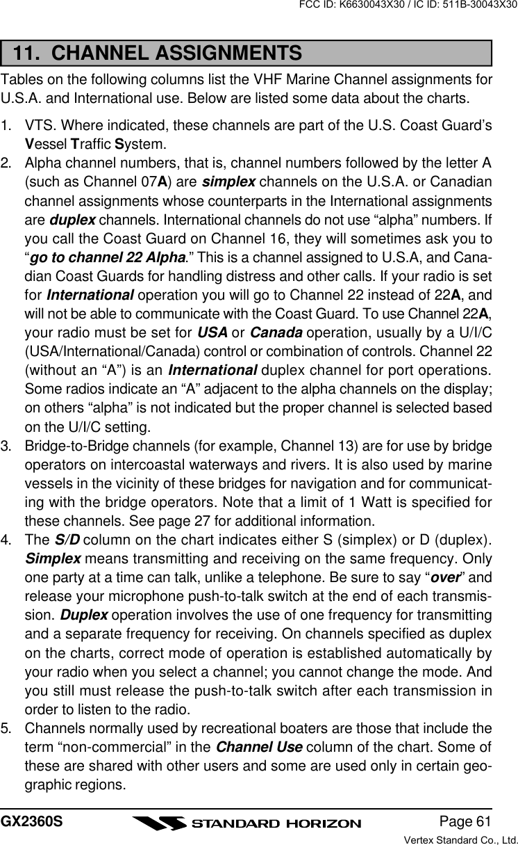
![GX2360SPage 549 RAM+ MIC OPERATIONIf the enhanced optional RAM+ Mic (CMP25) is connected to the remote micro-phone connector on the transceiver’s rear panel, the transceiver can use theremote control operation except for a few functions. The RAM+ Mic suppliedwith 23 feet (7 m) of routing cable and can be extended up to 70 feet (21 m)using three 23 feet extension cables model CT-100. The intercom operationcan be used between the RAM+ Mic and the transceiver.9.1 RAM+ MIC CONTROLSSQUELCH CONTROL (SQL)Activates the squelch adjusting mode.Press this key to activate the squelch adjusting mode. Press themicrophone’s [p] or [q] key to adjust the squelch.When this key is pressed and held down for 1 second or more, the squelchis turned off.VOLUME KEY (VOL)Activates the volume adjusting mode.Press this key to activate the volume adjusting mode. Press themicrophone’s [p] or [q] to adjust the volume.SCAN DWNAVWXCALLSETMEM ICU.I.CMENU169FCC ID: K6630043X30 / IC ID: 511B-30043X30Vertex Standard Co., Ltd.](https://usermanual.wiki/Yaesu-Musen/30043X30/User-Guide-366783-Page-54.png)
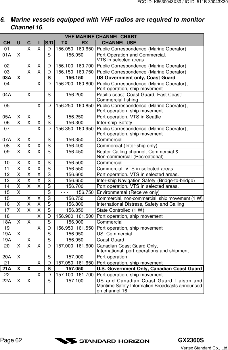
![Page 55GX2360SPOWER SWITCH (PWR)Press and hold down this key to turn to the transceiver and RAM+ Mic onand off.PTT (Push-To-Talk) SWITCHActivates transmission.[H/L] KEYToggles between high and low power. When the [H/L] key is pressed whilethe transceiver is on channel 13 or 67, the power will temporarily switchfrom LO to HI power until the PTT is released. The [H/L] key does notfunction on transmit inhibited and low power only channels.[p](UP)/[q](DOWN) KEYThese keys are used to select channels, adjusts the volume and squelchlevel, and to choose the item selection of different functions (such as theDSC operation). In many ways, these keys emulate the function of thetransceiver’s CHANNEL selector knob.[16/9] KEYImmediately recalls channel 16 from any channel location. Holding downthis key recalls channel 9. Pressing the [16/9] key reverts to the previousselected working channel.Secondary usePlease see secondary use for the [WX] and [MEM] key.KEY PAD[SCAN] Key1. Starts and stops scanning of programmed channels.2. If held while the [UP(p)] or [DOWN(q)] key on the microphone arepressed or CHANNEL selector knob on radio is turned, the radio willshow the channels programmed in scan memory. This function willnot work if the unit is scanning.NOTE: The priority channel is channel 16 only.[CALL/SET] KeyThe [CALL/SET] key functions as the enter key.Secondary usePress the [CALL/SET] key to access the DSC OPERATION menu.Press and hold the [CALL/SET] key to access the SETUP menu.FCC ID: K6630043X30 / IC ID: 511B-30043X30Vertex Standard Co., Ltd.](https://usermanual.wiki/Yaesu-Musen/30043X30/User-Guide-366783-Page-55.png)
![GX2360SPage 56[DW] KeyWatches for a transmission on CH16 and another selected channel untileither signal is received. (Dual watch)NOTE: When the DSC SCANNING feature is enabled (see section 7.15DSC SCAN), the radio watches for a transmission on CH16, anotherselected channel, and CH70 until either signal is received (Triple watch).Secondary usePress and hold [DW] key, intercom operation will operate between radioand RAM Mic.[NAV] KeyPress and hold this key, when connected to the GPS receiver, the LCDdisplays Position Data, Time, SOG (Speed Over Ground), and COG (CourseOver Ground) from the GPS.[WX] KeyImmediately recalls the previously selected NOAA weather channel fromany channel location.Secondary use1. Holding down the [16/9] key while pressing the [WX] key changes themode from USA to International or Canadian.NOTE: If position is displayed, this icon will be hidden.2. Holding down the [WX] and [SCAN] key while turning the power on re-sets the microprocessor and erases scan channels from memory. Thisclears the memory and establishes the factory-set defaults. For a list ofthese defaults, see the section on Resetting the Transceiver’s Micropro-cessor.[DISTRESS] KEYUsed to send a DSC Distress Call. To send the distress call:1. Lift the red rubber cover.2. Press and hold the Red button. The RAM+ display willcount down (3-2-1) and then transmit the Distress call.3. When the distress signal is sent, Ch70 and “TX” icon willappear on the LCD. After the message has been sent,the radio will sound a Distress Alarm.4. The transceiver “shadow-watches” for a transmission onCH16 or CH70 until an acknowledgment signal is re-ceived. “DISTRESS” and “WAITING” will appear on theLCD.5. If an acknowledgement is received, select channel 16 andadvise your distress situation.FCC ID: K6630043X30 / IC ID: 511B-30043X30Vertex Standard Co., Ltd.](https://usermanual.wiki/Yaesu-Musen/30043X30/User-Guide-366783-Page-56.png)
![Page 57GX2360S6. If no acknowledgment is received, the distress call is repeated in 4 minuteintervals until an acknowledgment is received.7. When a DSC Distress acknowledgment is received, a distress alarmsounds and channel 16 is automatically selected. The LCD shows theMMSI of the ship responding to your distress.RECEIVED ACK: acknowledgment signal is received.RECEIVED RLY: relay signal is received from another vessel or coaststation.8. To cancel the DSC distress alarm signal from the speaker, press anykey.9.2 INTERCOM OPERATION9.2.1 Communication1. Press and hold the [DW] key while in the “RADIO” mode,the mode is changed to “INTERCOM” mode.2. If your QUANTUM is equipped two RAM+ Mic, select thecompanion you wish to communicate (RADIO, RAM, or ALL)with the [p]/[q] key, then press the [CALL/SET] key to ter-minated.3.When the “INTERCOM” operation is activated, “IC” is dis-played on the RAM+ Mic and “INTERCOM” is displayed onthe QUANTUM.4.Press the PTT switch. The “TALK” isdisplayed.NOTE: A warning beep is emittedwhen the RAM+ Mic PTT switch ispressed while the transceivermicrophone’s PTT switch is pressed.5.Speak slowly and clearly into the mi-crophone, hold the microphone about1/2 inch away from your mouth.6.When finished, release the PTT switch.7. Press the [DW] key again the mode will revert to “RADIO” mode.9.2.2 CallingHold down the [DW] key for 1 second or more, when the “INTERCOM” opera-tion is activated. A calling beep is emitted twice from the transceiver speaker.(RAM+ Mic’s PTT switch is pressed)(MATRIX’s PTT switch is pressed)FCC ID: K6630043X30 / IC ID: 511B-30043X30Vertex Standard Co., Ltd.](https://usermanual.wiki/Yaesu-Musen/30043X30/User-Guide-366783-Page-57.png)
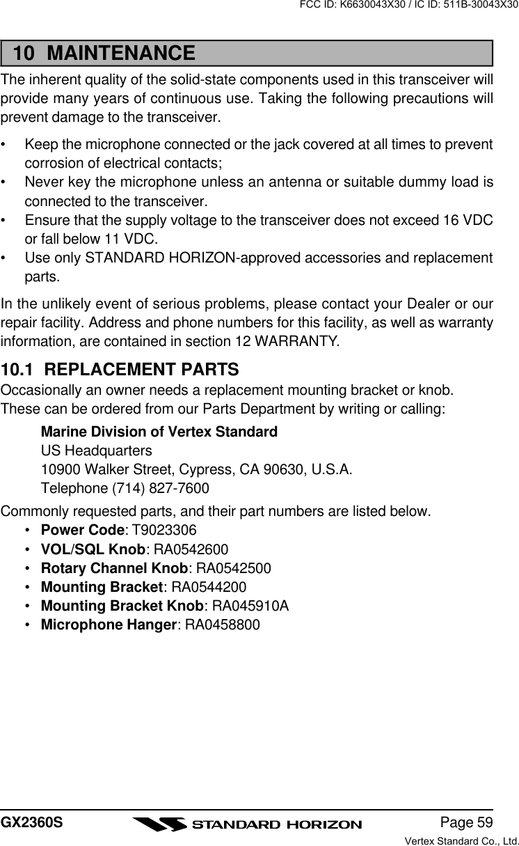
![GX2360SPage 589.3 DSC/RADIO SETUP MODEThe CMP25 can access the DSC / RADIO setup menu (refer to section 7“DSC/RADIO SETUP” for details). However, the LAMP, CONTRAST, and KEYBEEP menu item which is accessed from the CMP25 only controls the CMP25’sdisplay and speaker.DSC/RADIO Setup mode from the CMP25:1. Press and hold down the [CALL/SET] key until “RADIO SETUP” menuappears.2. Press the [p]/[q] key to select “RADIO SET” or “DSC SETUP” menu.3. Press the [CALL/SET] key, then select the menu item you wish to work onby pressing the [p]/[q] key.4. Press the [CALL/SET] key.5. Press the [p]/[q] key to change the value or condition for the menu item,then press the [CALL/SET] key to save the new setting.6. Press the [p]/[q] key to select “EXIT,” then press the [CALL/SET] key toreturn to the normal operation.RADIO SETUP-menu DSC SETUP-menuFCC ID: K6630043X30 / IC ID: 511B-30043X30Vertex Standard Co., Ltd.](https://usermanual.wiki/Yaesu-Musen/30043X30/User-Guide-366783-Page-58.png)