Yaesu Musen 30063X30 MARINE MOBILE TRANSCEIVER User Manual GX3500S p65
Yaesu Musen Co., Ltd. MARINE MOBILE TRANSCEIVER GX3500S p65
UserManual.wiki
>
Yaesu Musen
>
30063X30 User Manual
USERS MANUAL
Navigation menu
Upload a User Manual
Namespaces
Wiki Guide
HTML
PDF
Info
Views
User Manual
Discussion / Help
Navigation
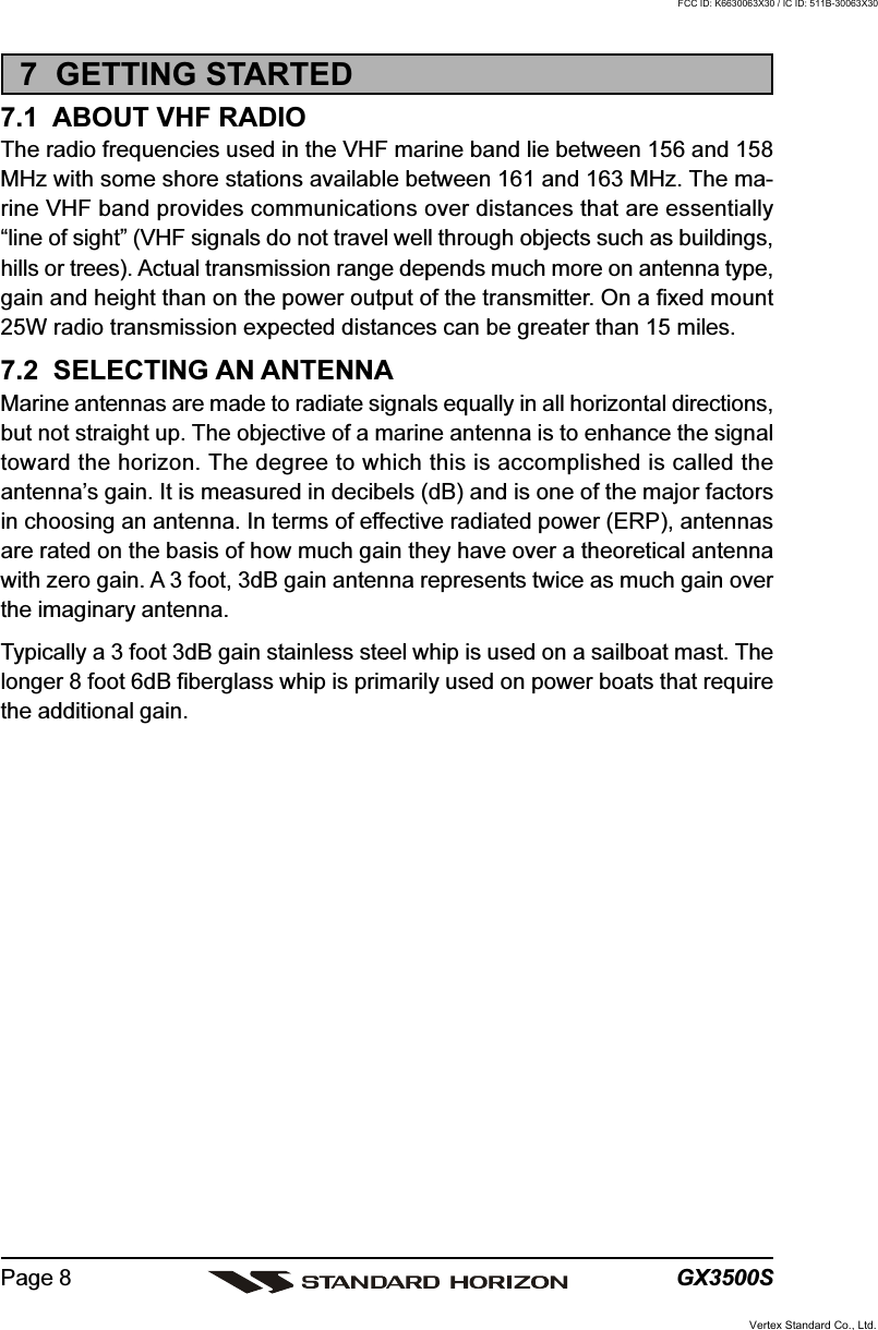
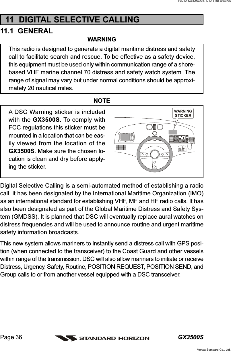
![GX3500SPage 128.4 CONNECTION OF GPS WITH NMEA OUTPUT• The GPS must have the NMEA Output turned on and set to 4800 Baud inthe setup menu. If there is a selection for parity select none.• For further information on interfacing /setting up your GPS. Please contactthe manufacturer of the GPS receiver.•GX3500S can read NMEA-0183 version 2.0 or higher.• The NMEA supported sentences are:Input: GLL, GGA, RMC and GNS (RMC sentence is recommended)Output: DSC and DSE(DSC sentences to Standard Horizon Plotter for Position Polling)If you have further inquires, please feel free to contact Product Support at:Phone: (800) 767-2450Email: marinetech@vxstdusa.com8.5 CHECKING GPS CONNECTIONSAfter connections have been made between the GX3500S and the GPS, asmall satellite icon will appear on the top right corner ofthe LCD display. To see additional GPS information, pressthe [F] key momentarily, then press the [6(NAV)] key.The GX3500S shows the Date, Time, SOG and COG.Manufacturer/ModelLowrance PortableMagellan Fixed MountMagellan PortableNorthstarRaytheon 420Raytheon 520 / 620Raytheon RL SERIESSimradSitex Neptune, NautilusWiresOrangeBlack (GND)GrayBlack (GND)OrangeBlack (GND)YellowBlack (GND)YellowBrownBlueBrownWhiteBrownWhiteBrownGrayBrownGX3500SBlueGreenBlueGreenBlueGreenBlueGreenBlueGreenBlueGreenBlueGreenBlueGreenBlueGreenWiresGreenBlueBrownWhiteBlueWhiteBlackBlueBlack (GND)BrownBlack (GND)YellowGreenGreenBlackWhiteBlackWhiteBlack (GND)Manufacturer/ModelSTANDARD HORIZONFuruno GP30, 36Furuno GP1650, 1850Garmin Fixed MountsGarmin PortablesJRC GPS500JRC 100 SERIESJRC 200 SERIESLowrance Fixed MountGX3500SGreenGrayBlueBlueGreenBlueGreenBlueGreenBlueGreenBlueGreenBlueGreenBlueGreenBlueGreenVertex Standard Co., Ltd.FCC ID: K6630063X30 / IC ID: 511B-30063X30](https://usermanual.wiki/Yaesu-Musen/30063X30/User-Guide-465253-Page-12.png)
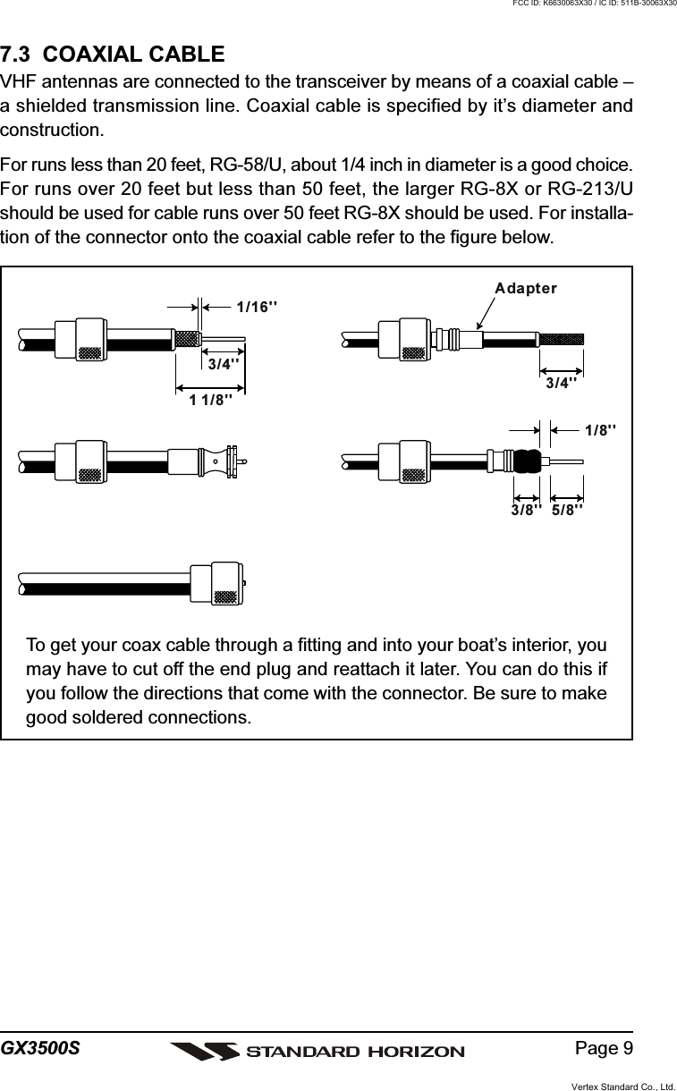
![Page 13GX3500S8.6 CHANGING THE GPS TIMEFrom the Factory the GX3500S shows GPS satellite time or UTC time. A timeoffset is needed to show the local time in your area.1. Press and hold down the [CALL(MENU)] key until“Radio Setup” menu appears.2. Press the [ENT] key, then select “Time Set” with theCHANNEL selector knob.3. Press the [ENT] key.4. Turn the CHANNEL selector knob to select time off-set from UTC. See illustration below to find your off-set time from UTC. If “0:00” is assigned, the time isthe same as UTC (Universal Time Coordinated orGMT Greenwich Mean Time).5. Press the [ENT] key to store the time offset.6. Press the [16/9] key or turn the CHANNEL selector knob to select “Exit,”then press the [ENT] key to return to the “Radio Setup” menu, select “Exit”and press the [ENT] key to return to radio operation.OFFSET TIME TABLEVertex Standard Co., Ltd.FCC ID: K6630063X30 / IC ID: 511B-30063X30](https://usermanual.wiki/Yaesu-Musen/30063X30/User-Guide-465253-Page-13.png)
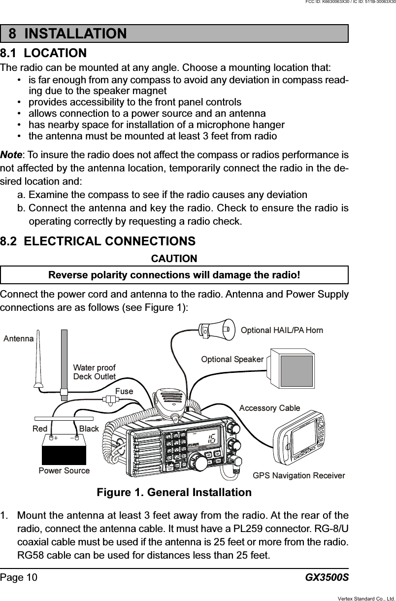
![GX3500SPage 148.7 CHANGING THE TIME LOCATIONYou may select the time display between local time and UTC (time GPS sendsto radio). Time is displayed when GPS position (LAT/LON) is displayed by press-ing the [F] key followed by the [6(NAV)] key.1. Press and hold down the [CALL(MENU)] key until“Radio Setup” menu appears.2. Press the [ENT] key, then select “Time Disp” in the“Radio Setup” menu with the CHANNEL selectorknob.3. Press the [ENT] key.4. Turn the CHANNEL selector knob to select “UTC” or“Local.”5. Press the [ENT] key to store the selected setting.6. To exit this menu and return to radio operation modepress the [16/9] key.In the local time mode, the display shows the time by the 12-hour system.Meanwhile, the display shows the time by the 24-hour system in the UTC mode.(“UTC” mode)(“LOCAL” mode)Vertex Standard Co., Ltd.FCC ID: K6630063X30 / IC ID: 511B-30063X30](https://usermanual.wiki/Yaesu-Musen/30063X30/User-Guide-465253-Page-14.png)
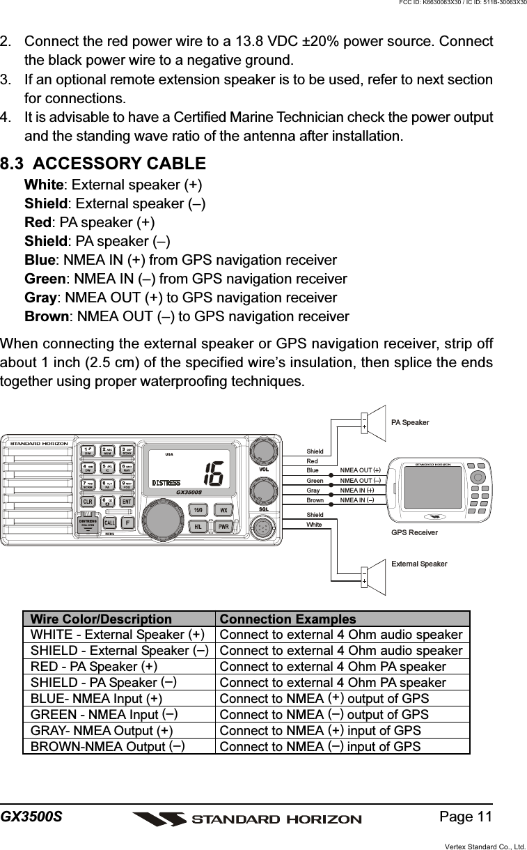
![Page 15GX3500S8.8 CHANGING COG TO TRUE OR MAGNETICAllows customizing the NAV data showing GPS Course Over Ground (COG).Factory default is True however following the steps below the COG can bechanged to Magnetic.1. Press and hold down the [CALL(MENU)] key until“Radio Setup” menu appears.2. Press the [ENT] key, then select “Magnetic” with theCHANNEL selector knob.3. Press the [ENT] key.4. Turn the CHANNEL selector knob to select “On” (rep-resenting “Magnetic”) or “Off” (representing “True”).5. Press the [ENT] key to store the selected setting.6. Turn the CHANNEL selector knob to select “Exit,”then press the [ENT] key to return to the “RadioSetup” menu, select “Exit” and press the [ENT] keyto return to radio operation.Vertex Standard Co., Ltd.FCC ID: K6630063X30 / IC ID: 511B-30063X30](https://usermanual.wiki/Yaesu-Musen/30063X30/User-Guide-465253-Page-15.png)
![Page 17GX3500S8.10 OPTIONAL ENHANCED RAM+ SECOND STATION MIC INSTALLATIONThe GX3500S is capable of using up to 2 Enhanced RAM+ mics to remotelycontrol the Radio, DSC and PA/Fog functions. In addition the GX3500S canoperate as a full function intercom system. With 2 RAM+ mics connected theGX3500S or RAM+ mics can selective call each station individually or all at onetime.1. Connect the RAM+ MIC Cable to the RAM MIC CONNECTOR on the rearpanel, then tighten the Cable Nut (See Figure 3).2. Referring to Figure 3, make a 1.2” (30 mm) hole in the wall, then insert theRAM+ MIC Cable into this hole. Connect the Gasket and Mount Base to theRAM+ MIC Cable Connector using the Nut.3. Drill the four Screw holes (approx. 2 mm) on the wall, then install the MountingBase to the wall using four screws.4. Put the Rubber Cap on to the Nut. The installation is now complete.5. Wires for a external speaker are provided on the RAM+ mic cable. Connectany 8 Ohm external speaker. When connected the RAM+ controls the vol-ume level of this speaker.RAM+ or External Speaker SelectionBy default the RAM+ internal speaker is turned on, however using the RAM+mic this speaker can be turned off so the external speaker can be used.1. Press and hold the [CALL/SET] key on the RAM+ Mic.2. Using the [] or [] keys to select “RAMSPK” and press the [CALL/SET] key.3. Press the [] or [] key to turn the RAM+Speaker “oF.”4. Press the [16/9] key to exit this mode.Figure 3. Enhanced RAM+ MIC InstallationWall GasketMounting BracketRAM MIC CableCapNutEXP SP Cable for the RAM+ MICVertex Standard Co., Ltd.FCC ID: K6630063X30 / IC ID: 511B-30063X30](https://usermanual.wiki/Yaesu-Musen/30063X30/User-Guide-465253-Page-17.png)
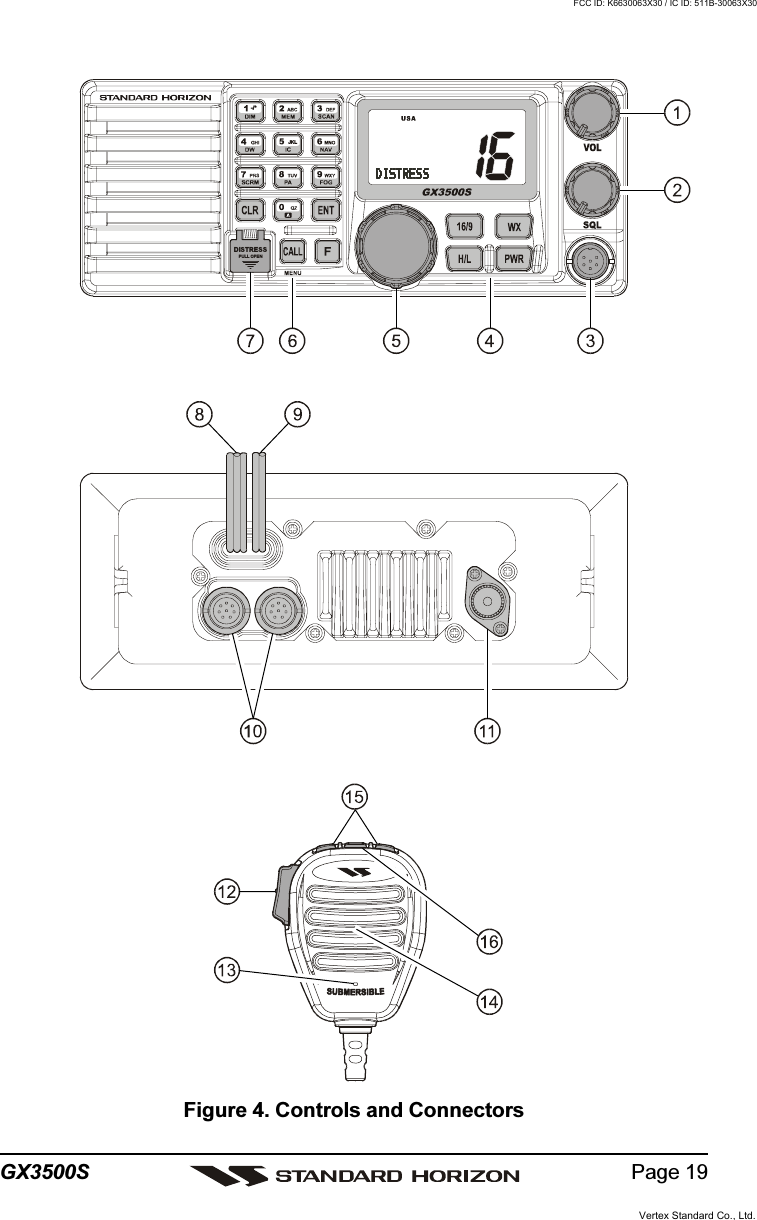
![GX3500SPage 189 CONTROLS AND INDICATORSNOTEThis section defines each control of the transceiver. See Figure 4 forlocation of controls. For detailed operating instructions refer to section“10 BASIC OPERATION.”VOLUME CONTROL (VOL)Adjusting this control clockwise, increases the audio volume level.SQUELCH CONTROL (SQL)Adjusting this control clockwise, sets the point at which random noise onthe channel does not activate the audio circuits but a received signal does.This point is called the squelch threshold. Further adjustment of the squelchcontrol will degrade reception of wanted transmissions.MICROPHONE CONNECTORConnect the supplied MH-63A6 Hand Microphone to this jack.KEY BUTTON[16/9] KeyImmediately recalls channel 16 from any channel location. Holding downthis key recalls channel 9. Pressing the [16/9] key again reverts to theprevious selected working channel.Secondary usePress and hold the [16/9] key then press the [WX] key to switch theChannel Group.[WX] KeyImmediately recalls the previously selected NOAA weather channel fromany channel.Secondary useHolding down the [16/9] key while pressing the [WX] key changes theChannel Group.[H/L] KeyToggles between 25 W (High) and 1 W (Low) power. When the [H/L] keyis pressed while the transceiver is on channel 13 or 67, the power willtemporarily switch from LO to HI power until the PTT is released.The [H/L] key does not function on transmit inhibited and low power onlychannels.Vertex Standard Co., Ltd.FCC ID: K6630063X30 / IC ID: 511B-30063X30](https://usermanual.wiki/Yaesu-Musen/30063X30/User-Guide-465253-Page-18.png)
![GX3500SPage 20[PWR] KeyTurns the transceiver on and off. To turn the transceiver on, press andhold this key until the LCD turns on. To turn it off, press and hold this keyuntil the LCD turns off. When the power is turned on, the transceiver isset to the last selected channel.CHANNEL SELECTOR KNOBRotary knob used to select channels and to choose menu items (such as theDSC menu, radio setup menu, and DSC setup menu). The [UP()] /[DOWN()] keys on the microphone can also be used to select channels andmenu items.When the PA/FOG mode is activated, the CHANNEL selector knob adjustthe audio output level.Secondary Use (Depends on the transceiver version)While holding down the [SCAN] key and turning the CHANNEL selectorknob, you can confirm memory channels for scanning.KEYPAD[1(DIM)] KeyWhen in radio mode, this key is used to directly select channel digit “1” ina channel number.Secondary usePress the [F] key first then press the [1(DIM)] key, access the LCD Dim-mer menu. Refer to section “10.15 LCD DIMMER” for details.[2(MEM)] KeyWhen in radio mode, this key is used to directly select channel digit “2” ina channel number.Secondary use (Depends on the transceiver version)Press the [F] key first then press the [2(MEM)] key, memorize the se-lected channel into the transceiver scan memory for scanning. Whenrepeat the same procedures ([F] [2(MEM)]), DELETES the channelfrom the scan memory. Refer to section “10.12 SCANNING” for details.[3(SCAN)] KeyWhen in radio mode, this key is used to directly select channel digit “3” ina channel number.Secondary use (Depends on the transceiver version)Press the [F] key first then press the [3(SCAN)] key, start and stop thescanning of programmed channels. Refer to section “10.12 SCANNING”for details.Vertex Standard Co., Ltd.FCC ID: K6630063X30 / IC ID: 511B-30063X30](https://usermanual.wiki/Yaesu-Musen/30063X30/User-Guide-465253-Page-20.png)
![Page 21GX3500S[4(DW)] KeyWhen in radio mode, this key is used to directly select channel digit “4” ina channel number.Secondary use (Depends on the transceiver version)Press the [F] key first then press the [4(DW)] key, scan for voice commu-nications on the priority channel and another selected channel until asignal is received on either channel (Dual Watch). Refer to section “10.11DUAL WATCH (TO PRIORITY CHANNEL)” for details.[5(IC)] KeyWhen in radio mode, this key is used to directly select channel digit “5” ina channel number.Secondary usePress the [F] key first then press the [5(IC)] key, when the optional RAM+Mic is connected, intercom operation will operate between radio and RAM+Mic. Refer to section “10.16 INTERCOM OPERATION” for details.[6(NAV)] KeyWhen in radio mode, this key is used to directly select channel digit “6” ina channel number.Secondary usePress the [F] key first then press the [6(NAV)] key, the LCD displays NAVGPS Data, Time, SOG (Speed Over Ground), and COG (Course OverGround) when a GPS is connected to the accessory cable of theGX3500S. See section “8.4 CONNECTION OF GPS WITH NMEA OUT-PUT” for details.[7(SCRM)] KeyWhen in radio mode, this key is used to directly select channel digit “7” ina channel number.Secondary usePress the [F] key first then press the [7(SCRM)] key, when the optionalCVS2500 Voice Scrambler Unit is installed, available to operate the VoiceScrambler function. Refer to section “10.17 VOICE SCRAMBLER” fordetails.[8(PA)] KeyWhen in radio mode, this key is used to directly select channel digit “8” ina channel number.Secondary usePress the [F] key first then press the [8(PA)] key, available to operate the30 Watt PA function. Refer to section “10.13 PA/FOG OPERATION” fordetails.Vertex Standard Co., Ltd.FCC ID: K6630063X30 / IC ID: 511B-30063X30](https://usermanual.wiki/Yaesu-Musen/30063X30/User-Guide-465253-Page-21.png)
![GX3500SPage 22[9(FOG)] KeyWhen in radio mode, this key is used to directly select channel digit “9” ina channel number.Secondary usePress the [F] key first then press the [9(FOG)] key, available to operatethe Fog Horn function. Refer to section “10.13 PA/FOG OPERATION”for details.[0] KeyWhen in radio mode, this key is used to directly select channel digit “0” ina channel number.[CLR] KeyPress the [CLR] Key to cancel the menu selection and/or keypad entry.[ENT] KeyPress the [ENT] Key to determine the menu selection and/or keypadentry.[CALL(MENU)] KeyPress the [CALL(MENU)] key to access the DSC OPERATION menu.The “INDIVIDUAL CALL,” “GROUP CALL,” and “ALL SHIPS CALL” func-tions can be accessed from the DSC OPERATION menu.Secondary usePress and hold the [CALL(MENU)] key to access the “Radio Setup”(refer to section “12 RADIO SETUP”) or “DSC Setup” menu (refer tosection “11 DIGITAL SELECTIVE CALLING”).“Radio Setup” menu “DSC Setup” menuVertex Standard Co., Ltd.FCC ID: K6630063X30 / IC ID: 511B-30063X30](https://usermanual.wiki/Yaesu-Musen/30063X30/User-Guide-465253-Page-22.png)
![Page 23GX3500S[F] KeyPress the [F] key to activate the “Alternate” key function.[DISTRESS] KeyUsed to send a DSC Distress Call. To send the distress call refer to section“11.3.1 (Transmitting A DSC Distress Call).”ACCESSORY CONNECTION CABLEConnects the GX3500S to a GPS, a PA speaker, and an external speaker.DC INPUT CABLEConnects the radio to a DC power supply capable of delivering 12V DC.RAM+ MIC CONNECTORSConnects the GX3500S to the enhanced RAM+ MIC (Remote Access Mi-crophone). Refer to section “13 ENHANCED RAM+ MIC OPERATION” fordetails.ANTENNA JACKConnects an antenna to the transceiver. Use a marine VHF antenna withan impedance of 50 ohms.PTT (Push-To-Talk) SWITCHKeys the transmitter when the transceiver is in radio mode. If the transceiveris in the intercom operation mode (between the RAM+ and the GX3500S),or PA mode, it activates the GX3500S microphone for voice communica-tions.MICROPHONETransmits the voice message with reduction of background noise, usingClear Voice Noise Reduction Technology.MICROPHONE SPEAKERThe audio heard through internal radio speaker is heard through micro-phone speaker.[UP()] / [DOWN()] KEYSThe [UP()] and [DOWN()] on the microphone function the same as theCHANNEL selector knob on the front panel of the transceiver.[16/9] KeyPressing the [16/9] key immediately recalls channel 16 from any location.Press and hold the [16/9] key to recall channel 9. Pressing the [16/9] keyagain will revert the radio to the previous selected channel.Vertex Standard Co., Ltd.FCC ID: K6630063X30 / IC ID: 511B-30063X30](https://usermanual.wiki/Yaesu-Musen/30063X30/User-Guide-465253-Page-23.png)
![GX3500SPage 2410 BASIC OPERATION10.1 RECEPTION1. After the transceiver has been installed, ensure that the power supply andantenna are properly connected.2. Press and hold the [PWR] key until the radio turns on.3. Turn the SQL knob fully counterclockwise. This state is known as “squelch off”.4. Turn up the VOL knob until noise or audio from the speaker is at a comfort-able level.5. Turn the SQL knob clockwise until the random noise disappears. This stateis known as the “squelch threshold.”6. Turn the CHANNEL selector knob to select the desired channel. Refer tothe channel chart on page 78 for available channels.7. The keypad on the front may be used to directly select channels. Exampleto select channel 68:1. Press [6(NAV)]2. Press [8(PA)]3. Press [ENT]In the USA and Canadian modes, press and hold in the [0] key to select the“A” channel. Example to select channel 22A:1. Press [2(MEM)]2. Press [2(MEM)]3. Press [0] until “A” appears to the right of the channel number4. Press [ENT]8. When a message is received, adjust the volume to the desired listeninglevel. The “ ” indicator in the LCD is displayed indicating that the chan-nel is being used.10.2 TRANSMISSION1. Perform steps 1 through 6 of RECEPTION.2. Before transmitting, monitor the channel to ensure it is clear.THIS IS AN FCC REQUIREMENT!3 Press the PTT (push-to-talk) switch. The “ ” indicator in the LCD isdisplayed.4. Speak slowly and clearly into the microphone.5. When the transmission is finished, release the PTT switch.NOTEThis is a noise-canceling microphone. The oval slot on the bottom ofmicrophone should be positioned within 1/2 inch (1.3 cm) from the mouthfor optimum performance.Vertex Standard Co., Ltd.FCC ID: K6630063X30 / IC ID: 511B-30063X30](https://usermanual.wiki/Yaesu-Musen/30063X30/User-Guide-465253-Page-24.png)
![Page 25GX3500S10.3 TRANSMIT TIME - OUT TIMER (TOT)When the PTT switch on the microphone is held down, transmit time is limited to5 minutes. This limits unintentional transmissions due to a stuck microphone.About 10 seconds before automatic transmitter shutdown, a warning beep will beheard from the speaker(s). The transceiver will automatically go to receive mode,even if the PTT switch is continually held down. Before transmitting again, the PTTswitch must first be released and then pressed again.10.4 SIMPLEX/DUPLEX CHANNEL USERefer to the VHF MARINE CHANNEL CHART (page 78) for instructions on useof simplex and duplex channels.NOTEAll channels are factory-programmed in accordance with International,Industry Canada (Canada), and FCC (USA) regulations. Mode of opera-tion cannot be altered from simplex to duplex or vice-versa.10.5 INTERNATIONAL, USA, AND CANADA MODE1. To change the modes, hold the [16/9] key and press the [WX] key. Themode changes from International to Canadian to USA with each press ofthe [WX] key.2. “INTL” will be displayed for International mode, and “CAN” will be displayedfor Canadian mode, and “USA” will be displayed on the LCD for USA mode.3. Refer to the VHF MARINE CHANNEL CHART (page 78) for allocated chan-nels in each mode.10.6 NOAA WEATHER CHANNELSNOTENOAA Weather channels are available in the waters of USA and Canada only.1. To receive a NOAA weather channel, press the [WX] key from any channel.The transceiver will go to the last selected weather channel.2. Turn the CHANNEL selector knob on the radio or [UP()] / [DOWN()]keys on the microphone to select a different NOAA weather channel.3. To exit from the NOAA weather channels, press the [WX] key. The trans-ceiver returns to the channel it was on prior to a weather channel.10.6.1 NOAA Weather AlertIn the event of extreme weather disturbances, such as storms and hurricanes,the NOAA (National Oceanic and Atmospheric Administration) sends a weatheralert accompanied by a 1050 Hz tone and subsequent weather report on one ofthe NOAA weather channels. When the Weather Alert feature is enabled (seeVertex Standard Co., Ltd.FCC ID: K6630063X30 / IC ID: 511B-30063X30](https://usermanual.wiki/Yaesu-Musen/30063X30/User-Guide-465253-Page-25.png)
![GX3500SPage 26section “12.9 WX ALERT”), the transceiver is capable of receiving this alert ifthe following is performed:1. Program NOAA weather channels into the transceiver’s memory for scan-ning. Follow the same procedure as for regular channels under section “10.12.”2. Press the [SCAN] key once to start memory scanning or hold down the[SCAN] key during memory scanning to start priority scanning.3. The programmed NOAA weather channels will be scanned along with theregular-programmed channels. However, scanning will not stop on a nor-mal weather broadcast unless a NOAA alert is received.4. When an alert is received on a NOAA weather channel, scanning will stop andthe transceiver will emit a loud beep to alert the user of a NOAA broadcast.5. Press the [WX] key to stop the alert tone and receive the weather report.NOTEIf the [WX] key is not pressed the alert tone will be emitted for 5 minutesand then the weather report will be received.NOTEThe Weather Alert feature is also engaged while the transceiver is re-ceiving on one of the NOAA weather channels.10.6.2 NOAA Weather Alert TestingNOAA tests the alert system ever Wednesday between 11AM and 1PM. To testthe QUANTUM’s NOAA Weather feature, on Wednesday between 11AM and1PM, setup as in previous section and confirm the alert is heard.10.7 EMERGENCY (CHANNEL 16 USE)Channel 16 is known as the Hail and Distress Channel. An emergency is de-fined as a threat to life or property. In such instances, be sure the transceiver ison and set to CHANNEL 16. Then use the following procedure:1. Press the microphone push-to-talk switch and say “Mayday, Mayday, May-day. This is , , ” (your vessel’s name).2. Then repeat once: “Mayday, ” (your vessel’s name).3. Now report your position in latitude/longitude, or by giving a true or mag-netic bearing (state which) to a well-known landmark such as a navigationaid or geographic feature such as an island or harbor entry.4. Explain the nature of your distress (sinking, collision, aground, fire, heartattack, life-threatening injury, etc.).5. State the kind of assistance your desire (pumps, medical aid, etc.).6. Report the number of persons aboard and condition of any injured.7. Estimate the present seaworthiness and condition of your vessel.Vertex Standard Co., Ltd.FCC ID: K6630063X30 / IC ID: 511B-30063X30](https://usermanual.wiki/Yaesu-Musen/30063X30/User-Guide-465253-Page-26.png)
![GX3500SPage 2810.9 MAKING TELEPHONE CALLSTo make a radiotelephone call, use a channel designated for this purpose, Thefastest way to learn which channels are used for radiotelephone traffic is to askat a local marina. Channels available for such traffic are designated PublicCorrespondence channels on the channel charts in this manual. Some ex-amples for USA use are Channels 24, 25, 26, 27, 28, 84, 85, 86, and 87. Callthe marine operator and identify yourself by your vessel’s name, The marineoperator will then ask you how you will pay for the call (telephone credit card,collect, etc.) and then link your radio transmission to the telephone lines.The marine telephone company managing the VHF channel you are using maycharge a link-up fee in addition to the cost of the call.10.10 OPERATING ON CHANNELS 13 AND 67Channel 13 is used at docks and bridges and by vessels maneuvering in port.Messages on this channel must concern navigation only, such as meeting andpassing in restricted waters.Channel 67 is used for navigational traffic between vessels.By regulation, power is normally limited to 1 Watt on these channels. Your radiois programmed to automatically reduce power to this limit on these channels.However, in certain situations it may be necessary to temporarily use a higherpower. See page 18 ([H/L] key) for means to temporarily override the low-powerlimit on these two channels.10.11 DUAL WATCH (TO PRIORITY CHANNEL)Dual watch allows the radio to monitor one channel and the assigned Prioritychannel. By default the priority channel is set to 16, however the priority chan-nel may be changed by referring to section 12.5 Priority Channel set.1. Adjust the SQL knob until the background noise disappears.2. Select the channel you wish to dual watch to “Priority channel.”3. Press the [F] key followed by the [4(DW)] key.The display will scan between Priority channel andthe channel that was selected in step 2.If a transmission is received on the channel selectedin step 2, the GX3500S will dual watch between theworking channel and the Priority channel.4. To stop Dual Watch, press the [CLR] key or press the [F] key followed bythe [4(DW)] key again.Vertex Standard Co., Ltd.FCC ID: K6630063X30 / IC ID: 511B-30063X30](https://usermanual.wiki/Yaesu-Musen/30063X30/User-Guide-465253-Page-28.png)
![Page 29GX3500S10.12 SCANNINGAllows the user to select the scan type from Memory scan or Priority scan.“Memory scan” scans the channels that were programmed into memory. “Pri-ority scan” scans the channels programmed in memory with the priority chan-nel.10.12.1 Selecting the Scan Type1. Press and hold down the [CALL(MENU)] key until“Radio Setup” menu appears.2. Press the [ENT] key, then select “SCAN Type” in the“Radio Setup” menu with the CHANNEL selectorknob.3. Press the [ENT] key.4. Turn the CHANNEL selector knob to select “Prior-ity” or “Memory.”5. Press the [ENT] key to store the selected setting.6. To exit this menu and return to radio operation modepress the [16/9] key.10.12.2 Memory Scanning (M-SCAN)1. Adjust the SQL knob until background noise disappears.2. Select a desired channel to be scanned using theCHANNEL selector knob. Press the [F] key followedby the [2(MEM)] key, “MEM” will appear on the LCDwhich indicates the channel has been programmedinto the transceivers memory.3. Repeat step 2 for all the desired channels to be scanned.4. To DELETE a channel from the transceiver’s memory, select the channelthen press the [F] key followed by the [2(MEM)] key, “MEM” will disappearin the LCD.5. To start scanning, press the [F] key followed by the[3(SCAN)] key.“M-SCAN” appears on the LCD. Scanning will pro-ceed from the lowest to the highest programmedchannel number and will stop on a channel when a transmission is received.6. The channel number will blink during reception.7. To stop scanning, press the [16/9], [WX], [CALL(MENU)], or PTT key.Vertex Standard Co., Ltd.FCC ID: K6630063X30 / IC ID: 511B-30063X30](https://usermanual.wiki/Yaesu-Musen/30063X30/User-Guide-465253-Page-29.png)
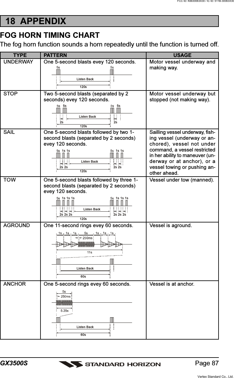
![GX3500SPage 3010.12.3 Priority Scanning (P-SCAN)In the default setting, Channel 16 is set as the priority channel. You may changethe priority channel to the desired channel from the Channel 16 by the RadioSetup Mode, refer to section “12.5 PRIORITY CHANNEL SET.”1. Adjust the SQL knob until background noise disappears.2. Select a desired channel to be scanned using theCHANNEL selector knob. Press the [F] key followedby the [2(MEM)] key, “MEM” will appear on the LCDwhich indicates the channel has been programmedinto the transceivers memory.3. Repeat step 2 for all the desired channels to be scanned.4. To DELETE a channel from the transceiver’s memory, select the channelthen press the [F] key followed by the [2(MEM)] key, “MEM” will disappearin the LCD.5. To start priority scanning, press the [F] key followedby the [3(SCAN)] key. “P-SCAN” appears on the LCD.Scanning will proceed between the memorized chan-nels and the priority channel. CH 16 the priority chan-nel will be scanned after each programmed channel.6. To stop scanning, press the [16/9], [WX], [CALL(MENU)], or PTT key.You may change the scan resume time by the Radio Setup Mode, refer tosection “12.7 SCAN RESUME TIME.”10.13 PA/FOG OPERATIONPA/FOG mode allows the transceiver to be used as a 30W hailer when anoptional STANDARD HORIZON 220SW or 240SW HAIL/PA Horn is installed.When in Hail mode the HAIL/PA Listen’s Back (acts as a microphone and sendssound to the front panel speaker) through the HAIL/PA speaker which providestwo-way communications through the HAIL/PA speaker.NOTEWhen in PA or FOG mode the GX3500S will receive the last selected VHFchannel before entering into the PA or FOG mode and receive DSC calls.PA HAIL mode: Allows the transceiver to be used as a power hailer whenan optional STANDARD HORIZON 220SW or 240SWHAIL/PA Horn is installed. The Hail mode has a listen-backfeature which provides two way communication throughthe HAIL/PA speaker.FOG HORN mode: Automatic signaling is transmitted through the HAIL/PAspeaker.Vertex Standard Co., Ltd.FCC ID: K6630063X30 / IC ID: 511B-30063X30](https://usermanual.wiki/Yaesu-Musen/30063X30/User-Guide-465253-Page-30.png)
![Page 31GX3500S10.13.1 Operating the PA HAIL mode1. Press the [F] key followed by the [8(PA)] key to acti-vate the PA HAIL mode.2. Press the PTT switch to speak through the HAIL/PAspeaker.Rotate the CHANNEL selector knob to control theAF output level. The AF output level can be set from0 to 30 watts.3. To exit the PA HAIL mode and return to radio opera-tion mode, press the [F] key followed by the [8(PA)] key again.10.13.2 Operating the FOG HORN modeOperator can select from Underway, Stop, Sail, Tow, Horn, Siren, Aground, orAnchor. Please refer to page 87 for FOG Horn Timing Chart.1. Press the [F] key followed by the [9(FOG)] key, acti-vate the “FOG HORN” menu.2. Turn the CHANNEL selector knob to select the oneof the eight functions described above.3. Press the [ENT] key.4. On the “Horn” and “Siren” modes, press the PTTswitch to activate the tone through the HAIL/PAspeaker.Rotate the CHANNEL selector knob to control theAF output level. The AF output level can be set from0 to 30 watts.5. To exit the “FOG HORN” mode and return to radio operation mode, pressthe [F] key followed by the [9(FOG)] key again.10.14 NAVIGATION INDICATIONThe transceiver has the ability to display Date, Time, SOG, COG, as well as theposition (LAT/LON), when connected to a GPS receiver.1. Press the [F] key followed by the [6(NAV)] key, dis-play the position information on the LCD. If the GPSreceiver is not receiving a fix, the display will be asshown in the illustration on the right.2. To hide the position information, press the [F] keyfollowed by the [6(NAV)] key again.Vertex Standard Co., Ltd.FCC ID: K6630063X30 / IC ID: 511B-30063X30](https://usermanual.wiki/Yaesu-Musen/30063X30/User-Guide-465253-Page-31.png)
![GX3500SPage 3210.15 LCD DIMMERAllows setting up the backlight intensity or to turn it off.1. Press the [F] key followed by the [1(DIM)] key to en-abling the setting up the backlight intensity.2. Turn the CHANNEL selector knob to select the de-sired backlight intensity. You will be able to see theeffects of your changes.3. When you have completed the adjustment, press the [F] key followed bythe [1(DIM)] key again, return to radio operation mode.10.16 INTERCOM OPERATIONIf the RAM+ Mic is connected to the GX3500S, you may communicate betweenthe GX3500S and RAM+ Mic, or RAM+ and RAM+ Mic (Refer to section “13.2INTERCOM OPERATION”).SCAN DWNAVWXCALLSETMEM ICU .I. CMENU169SCAN DWNAVWXCALLSETMEM ICU.I.CMENU169SCAN DWNAVWXCA LLSETMEM ICU .I. CMENU169SCAN DWNAVWXCA LLSETMEM ICU.I.CMENU169SCAN DWNAVWXCALLSETMEM ICU .I. CMENU169SCAN DWNAVWXCALLSETMEM ICU.I.CMENU169SCAN DWNAVWXCA LLSETMEM ICU .I. CMENU169SCAN DWNAVWXCA LLSETMEM ICU.I.CMENU169RAM 1RAM 1RAM 1RAM 1RAM 1 RAM 2RAM 1 GX3500SRAM 2RAM 2RAM 2RAM 2DIST RE SSPULL OPEN-/*JKLDIST RE SSPULL OPEN-/*JKLDISTRESSPULL OPE N-/*JKLDISTRESSPULL OPE N-/*JKLVertex Standard Co., Ltd.FCC ID: K6630063X30 / IC ID: 511B-30063X30](https://usermanual.wiki/Yaesu-Musen/30063X30/User-Guide-465253-Page-32.png)
![Page 33GX3500S10.16.1 Communication1. Press the [F] key followed by the [5(IC)] key, the modeis changed to “INTERCOM” mode.2. If your GX3500S is equipped two RAM+ Mic’s, se-lect the companion you wish to communicate (RAM1,RAM2, or ALL) with the CHANNEL selector knob, then press the [ENT] key.3. When the “INTERCOM” operation isactivated, “Intercom” is displayed onthe GX3500S, and “IC” is displayed onthe RAM+ Mic.4. Press the PTT switch. “Talk” will beshown on the display.NOTE: A warning beep will be emittedwhen the GX3500S microphone’s PTTswitch is pressed while the RAM+ Mic’sPTT switch is pressed.5. Speak slowly and clearly into the microphone, hold the microphone about1/2 inch away from your mouth.6. When finished, release the PTT switch.7. To exit the “INTERCOM” mode and return to radio operation mode, pressthe [F] key followed by the [5(IC)] key again.10.16.2 CallingPress and hold the [5(IC)] key for 1 second when the “INTERCOM” operation isactivated, a calling beep is emitted twice from the transceiver speaker.NOTEWhen both RAM+ microphones are set to inter-com mode, the GX3500S will be temporarily dis-abled until the RAM+(s) exit the RAM+ to RAM+intercom mode.(RAM+ Mic’s PTT switch is pressed)(GX3500S’s PTT switch is pressed)Vertex Standard Co., Ltd.FCC ID: K6630063X30 / IC ID: 511B-30063X30](https://usermanual.wiki/Yaesu-Musen/30063X30/User-Guide-465253-Page-33.png)
![GX3500SPage 3410.17 VOICE SCRAMBLERIf privacy of communications is desired, a CVS2500 voice scrambler (VS) canbe installed in the transceiver. Contact your Dealer to have a CVS2500 installed.1. Press the [F] key followed by the [7(SCRM)] key, thevoice scrambler is activated. “VS” will appear on theLCD.2. Press the [F] key then press and hold the [7(SCRM)]key for 1 second, the “SCRM Code” will appear.3. Turn the CHANNEL selector knob to change thescrambler code. The scrambler code can be set from“0” to “3.”4. Press the [ENT] key to save the scrambler code and return to radio opera-tion mode (with voice scrambler).5. Monitor the channel before transmitting.6. To disable the voice scrambler, press the [F] key followed by the [7(SCRM)]key again.Vertex Standard Co., Ltd.FCC ID: K6630063X30 / IC ID: 511B-30063X30](https://usermanual.wiki/Yaesu-Musen/30063X30/User-Guide-465253-Page-34.png)
![Page 37GX3500S11.2 MARITIME MOBILE SERVICE IDENTITY (MMSI)11.2.1 What is an MMSI?An MMSI is a nine digit number used on Marine Transceivers capable of usingDigital Selective Calling (DSC). This number is used like a telephone number toselectively call other vessels.THIS NUMBER MUST BE PROGRAMMED INTO THE RADIO TO OPERATETHE GX3500S DSC FUCTIONS.How can I obtain an MMSI assignment?Boat US offers online registration of a MMSI. Visit www.boatus.com/mmsi11.2.2 Programming the MMSIWARNINGUser MMSI can be input only twice. If the user tries to input an MMSImore than twice, the radio will show the display onthe right. If the user needs to change the MMSImore than twice, the transceiver will have to besent to Factory Service. Refer to the section “14.2.FACTORY SERVICE.”1. Press and hold down the [CALL(MENU)] key untilthe “Radio Setup” menu appears.2. Turn the CHANNEL selector knob to the left to se-lect “DSC Setup” menu.3. Press the [ENT] key, then select “User MMSI” withthe CHANNEL selector knob.4. Press the [ENT] key. The “User MMSI” number willappear, and the first digit will be flashing.5. Enter the your MMSI (up to nine digits) from the key-pad.6. Press and hold the [ENT] key to store the number inmemory.7. To exit this menu and return to radio operation modepress the [16/9] key.Vertex Standard Co., Ltd.FCC ID: K6630063X30 / IC ID: 511B-30063X30](https://usermanual.wiki/Yaesu-Musen/30063X30/User-Guide-465253-Page-37.png)
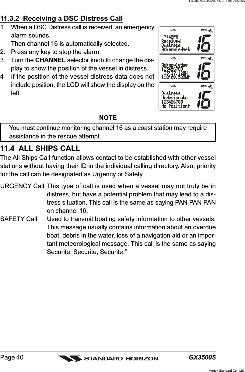
![GX3500SPage 3811.3 DSC DISTRESS CALLThe GX3500S is capable of transmitting and receiving DSC Distress messagesto all DSC radios. The GX3500S may be connected to a GPS to also transmitthe Latitude, Longitude of the vessel.11.3.1 Transmitting a DSC Distress CallNOTETo be able to transmit a DSC distress call an MMSI number must beprogrammed, refer to section “11.2.2 Programming the MMSI.”In order for your ships location to be transmitted a GPS must be connected tothe GX3500S, refer to section “8.4 CONNECTION OF GPS WITH NMEA OUT-PUT.”1. Lift the red spring loaded DISTRESS cover and press the [DISTRESS] key.The “DISTRESS” menu will appear on the LCD.2. Press and hold the [DISTRESS] key. The radios dis-play will count down (3-2-1) and then transmit theDistress call.3. When the distress signal is sent, CH70 and “ ”icon will appear on the LCD. After the message hasbeen sent, the radio will sound a Distress Alarm.4. The transceiver will watch for a DSC acknowledg-ment transmission on CH70 and also receive callson CH16.5. If an acknowledgement is received, select channel16 and advise your distress situation.6. If no acknowledgment is received, the distress call isrepeated in 4 minute intervals until a DSC acknowl-edgment is received.7. When a DSC Distress acknowledgment is received,a distress alarm sounds and channel 16 is automati-cally selected. The LCD shows the MMSI of the shipresponding to your distress.RECEIVED ACK: acknowledgment signal is received.RECEIVED RLY: relay signal is received from another vessel or coast station.8. To cancel the DSC distress alarm signal from the speaker, press any key.Vertex Standard Co., Ltd.FCC ID: K6630063X30 / IC ID: 511B-30063X30](https://usermanual.wiki/Yaesu-Musen/30063X30/User-Guide-465253-Page-38.png)
![Page 39GX3500STransmitting a DSC Distress Call with Nature of DistressThe GX3500S is capable of transmitting a DSC Distress Call with the following“Nature of Distress” categories:Undesignated, Fire, Flooding, Collision, Grounding, Capsizing, Sinking,Adrift, Abandoning, Piracy, MOB1. Lift the red spring loaded DISTRESS cover and press the [DISTRESS] key.The “DISTRESS” menu will appear on the LCD.2. Turn the CHANNEL selector knob to select the de-sired nature of distress category.3. Press and hold the [DISTRESS] key. The radios dis-play will count down (3-2-1) and then transmit theDistress call.4. When the distress signal is sent, CH70 and “ ”icon will appear on the LCD. After the message hasbeen sent, the radio will sound a Distress Alarm.5. The transceiver will watch for a DSC acknowledg-ment transmission on CH70 and also receive callson CH16.6. If an acknowledgement is received, select channel16 and advise your distress situation.7. If no acknowledgment is received, the distress call isrepeated in 4 minute intervals until a DSC acknowl-edgment is received.8. When a DSC Distress acknowledgment is received,a distress alarm sounds and channel 16 is automati-cally selected. The LCD shows the MMSI of the shipresponding to your distress.RECEIVED ACK: acknowledgment signal is received.RECEIVED RLY: relay signal is received from another vessel or coast station.9. To cancel the DSC distress alarm signal from the speaker, press any key.Cancel a DSC Distress CallIf a DSC Distress call was sent by error the GX3500Sallows you to send a message to other vessels to cancelthe Distress Call that was made in error.Press the [CLR] key, then press the [ENT] key.Vertex Standard Co., Ltd.FCC ID: K6630063X30 / IC ID: 511B-30063X30](https://usermanual.wiki/Yaesu-Musen/30063X30/User-Guide-465253-Page-39.png)
![Page 41GX3500S11.4.1 Transmitting an All Ships Call1. Press the [CALL(MENU)] key. The “DSC Operation”menu will appear.2. Turn the CHANNEL selector knob to select “All Ships.”3. Press the [ENT] key. (To cancel, turn the CHANNELselector knob to select “Exit.”)4. Turn the CHANNEL selector knob to select the call(“Urgency” or “Safety”).5. Press the [ENT] key to transmit the selected type ofall ships DSC call.6. After the ALL SHIPS CALL is transmitted, the trans-ceiver will switch to CH16.7. Listen to the channel to make sure it is not busy, thenkey the microphone and say PAN PAN PAN or“Securite, Securite, Securite” depending on the pri-ority of the call. Say your call sign and announce thechannel you wish to switch to for communications.11.4.2 Receiving an All Ships Call1. When an all ships call is received, an emergencyalarm sounds.The radio will automatically change to channel 16.2. Press any key to stop the alarm.3. Turn the CHANNEL selector knob to see the MMSIof the vessel transmitting the All Ships Call.4. Monitor channel 16 or traffic channel until the UR-GENCY voice communication is completed.Vertex Standard Co., Ltd.FCC ID: K6630063X30 / IC ID: 511B-30063X30](https://usermanual.wiki/Yaesu-Musen/30063X30/User-Guide-465253-Page-41.png)
![GX3500SPage 4211.5 INDIVIDUAL CALLThis feature allows the GX3500S to contact another vessel with a DSC VHFradio and automatically switch the receiving radio to a desired communicationschannel. This feature is similar to calling a vessel on CH16 and requesting togo to another channel (switching to the channel is private between the twostations).11.5.1 Setting up the Individual / Position Call DirectoryThe GX3500S has a DSC directory that allows you to store a vessel or person’sname and the MMSI number associated with vessels you wish to transmit Indi-vidual calls, Position Requests and Position Send transmissions.To transmit an Individual call you must program this directory with informationof the persons you wish to call, similar to a cellular phones telephone directory.1. Press and hold down the [CALL(MENU)] key until“Radio Setup” menu appears.2. Turn the CHANNEL selector knob to select “DSCSetup” menu.3. Press the [ENT] key, then select “INDIV DIR” with theCHANNEL selector knob.4. Press the [ENT] key, then select “Add” with the CHAN-NEL selector knob.5. Press the [ENT] key.6. Press the one of the Keypad keys to enter the firstletter of the name of the vessel or person you want toreference in the directory.Example: Press the [2(MEM)] key repeatedly to toggleamong the seven available characters associatedwith that key: 2 A B C a b c.If a mistake was made entering in the name, press-ing the [CLR] key to delete the wrong character.7. Press the [ENT] key to store the first letter in the nameand step to the next letter to the right.8. Repeat step 6 and 7 until the name is complete. Thename can consist of up to eleven characters, if youdo not use all eleven characters press the [ENT] key to move to the nextspace. This method can also be used to enter a blank space in the name.To clear the previous letter, press the [CLR] key.9. After the eleventh letter or space has been entered, press the [ENT] key toadvance to the MMSI (Maritime Mobile Service Identity Number) numberentry.Vertex Standard Co., Ltd.FCC ID: K6630063X30 / IC ID: 511B-30063X30](https://usermanual.wiki/Yaesu-Musen/30063X30/User-Guide-465253-Page-42.png)
![Page 43GX3500S10. Enter the MMSI number by the keypad. If a mistakewas made entering in the number, pressing the [CLR]key to delete the wrong character.11. To store the data entered, press and hold the [ENT]key.12. To enter another individual address, repeat steps 4 through 12.13. To exit this menu and return to radio operation mode press the [16/9] key.NOTESelecting “Next” or “Exit” will automatically save the name and MMSInumber into memory.11.5.2 Setting up Individual ReplyAllows setting up the radio to automatically (default setting) or manually re-spond to a DSC Individual call requesting you to switch to a working channel forvoice communications. When Manual is selected the MMSI of the calling ves-sel is shown allowing you to see who is calling. This function is similar to callerid on a cellular phone.1. Press and hold down the [CALL(MENU)] key until“Radio Setup” menu appears.2. Turn the CHANNEL selector knob to select “DSCSetup” menu.3. Press the [ENT] key, then select “INDIV Reply” withthe CHANNEL selector knob.4. Press the [ENT]key.5. Turn the CHANNEL selector knob to select “Auto”or “Manual.”6. Press the [ENT] key to store the selected setting.7. To exit this menu and return to radio operation modepress the [16/9] key.Vertex Standard Co., Ltd.FCC ID: K6630063X30 / IC ID: 511B-30063X30](https://usermanual.wiki/Yaesu-Musen/30063X30/User-Guide-465253-Page-43.png)
![GX3500SPage 4411.5.3 Setting up the Individual/Group Call RingerWhen a Individual Call or Group Call is received the radio will produce a ringingtone for 3 minutes. This selection allows the Individual Call ringer time to bechanged.1. Press and hold down the [CALL(MENU)] key until“Radio Setup” menu appear.2. Turn the CHANNEL selector knob to select “DSCSetup” menu.3. Press the [ENT] key, then select “INDIV Ring” withthe CHANNEL selector knob.4. Press the [ENT] key.5. Turn the CHANNEL selector knob to select ringingtime of a Individual Call.6. Press the [ENT] key to store the selected setting.7. To exit this menu and return to radio operation modepress the [16/9] key.The GX3500S has the capability to turn off the Individual call ringer.1. Press and hold down the [CALL(MENU)] key until“Radio Setup” menu appear.2. Turn the CHANNEL selector knob to select “DSCSetup” menu.3. Press the [ENT] key, then select “DSC Beep” with theCHANNEL selector knob.4. Press the [ENT] key.5. Turn the CHANNEL selector knob to select “Individual”if you wish to disable the Individual Call ringer, or“Group” if you wish to disable the Group Call ringerand press the [ENT] key.6. Turn the CHANNEL selector knob to select “Off.”7. Press the [ENT] key to store the selected setting.8. To exit this menu and return to radio operation modepress the [16/9] key.If you wish to return to enabling the ringer tone, just re-peat the above procedure, turning the CHANNEL selec-tor knob to select “On” in step “6” above.Vertex Standard Co., Ltd.FCC ID: K6630063X30 / IC ID: 511B-30063X30](https://usermanual.wiki/Yaesu-Musen/30063X30/User-Guide-465253-Page-44.png)
![Page 45GX3500S11.5.4 Transmitting an Individual CallThis feature allows the user to contact another vessel with a DSC radio. Thisfeature is similar to calling a vessel on CH16 and requesting to go to anotherchannel.Pre-Programmable Calling1. Press the [CALL(MENU)] key. The “DSC Operation”menu will appear.2. Turn the CHANNEL selector knob to select “Indi-vidual.” (To cancel, select “Exit” with the CHANNELselector knob or press the [16/9] key.)3. Press the [ENT] key. The transceiver will beep, andthe “Individual directory” will appear.4. Turn the CHANNEL selector knob to select the “Indi-vidual” you want to contact.5. Press the [ENT] key, then turn the CHANNEL selec-tor knob to select the operating channel you want tocommunicate on and press the [ENT] key.6. Press the [ENT] key again to transmit the individualDSC signal.7. After INDIVIDUAL CALL is transmitted, the trans-ceiver will wait 8 seconds for the acknowledgment. Ifthe reply signal is not received, the transceiver willtransmit again.8. After the second INDIVIDUAL CALL is transmitted, if the reply signal is notreceived, the display will be as shown in the illustra-tion on the right. To send the call again, press the[ENT] key.9. When an individual call acknowledgment is received,the established channel is automatically changed tothe channel which is selected on step 5 above and aringing tone sounds.10. Press any key to listen to the channel to make sure itis not busy, then key the microphone and call theother vessel you desire to communicate with.Vertex Standard Co., Ltd.FCC ID: K6630063X30 / IC ID: 511B-30063X30](https://usermanual.wiki/Yaesu-Musen/30063X30/User-Guide-465253-Page-45.png)
![GX3500SPage 46Manual CallingYou may enter an MMSI number manually to contact without the Setting up theIndividual Directory.1. Press the [CALL(MENU)] key. The “DSC Operation”menu will appear.2. Turn the CHANNEL selector knob to select “Indi-vidual.” (To cancel, select “Exit” with the CHANNELselector knob or press the [16/9] key.)3. Press the [ENT] key. The transceiver will beep, andthe “Individual directory” will appear.4. Turn the CHANNEL selector knob to select “Manual,”then press the [ENT] key.5. Enter the MMSI number (nine digits) which you wantto contact by the keypad, then press the [ENT] key.6. Turn the CHANNEL selector knob to select “Manual,”then press the [ENT] key.7. Turn the CHANNEL selector knob to select the oper-ating channel which you want to use for communica-tion, then press the [ENT] key.8. Press the [ENT] key again to transmit the individualDSC signal.9. After INDIVIDUAL CALL is transmitted, the trans-ceiver will wait 8 seconds for the acknowledgment. Ifthe reply signal is not received, the transceiver willtransmit again.10. After the second INDIVIDUAL CALL is transmitted, ifthe reply signal is not received, the display will be asshown in the illustration on the right. To send the callagain, press the [ENT] key or to exit the mode, pressthe [CLR] key.11. When an individual call acknowledgment is received,the established channel is automatically changed tothe channel which is selected on step 5 above and aringing tone sounds.9. Press any key to listen to the channel to make sure it is not busy, then keythe microphone and call the other vessel you desire to communicate with.Vertex Standard Co., Ltd.FCC ID: K6630063X30 / IC ID: 511B-30063X30](https://usermanual.wiki/Yaesu-Musen/30063X30/User-Guide-465253-Page-46.png)
![Page 47GX3500S11.5.5 Receiving an Individual CallWhen receiving an individual call, an acknowledgment must be sent back to thecalling station. The GX3500S default setting is Automatic, but has a selectionthat allows you to manually send a reply before the radio will switch to the re-quested calling channel. This selection is useful if you want to see who is callingand requesting you to switch to a channel for communications, similar to caller idon a cellular phone.1. When an individual call is received, an individual call ringing alarm sounds.The radio automatically switches to the requestedchannel.2. Press any key to stop the alarm.3. Press the PTT on the mic and talk to the calling ship.11.5.6 Setting Up the Call Waiting FunctionAllows the GX3500S to be setup to reply (ABLE) or set the radio so it transmitsa call that advises the calling vessel the person is UNABLE to reply to the call atthis time. This function is similar to an answering machine. When set up inUNABLE and a individual call is received the Individual call from the other ves-sel is logged in the CALL WAITING directory for you to review and call back ata later time.1. Press and hold down the [CALL(MENU)] key until“Radio Setup” menu appears.2. Turn the CHANNEL selector knob to select “DSCSetup” menu.3. Press the [ENT] key, then select “INDIV ACK” withthe CHANNEL selector knob.4. Press the [ENT] key.5. Turn the CHANNEL selector knob to select “Able” or“Unable.”6. Press the [ENT] key to store the selected setting.7. To exit this menu and return to radio operation modepress the [16/9] key.Vertex Standard Co., Ltd.FCC ID: K6630063X30 / IC ID: 511B-30063X30](https://usermanual.wiki/Yaesu-Musen/30063X30/User-Guide-465253-Page-47.png)
![GX3500SPage 4811.6 GROUP CALLThis feature allows the user to contact a group of specific vessels (examplemembers of a yacht club) using DSC radios with Group call function to auto-matically switch to a desired channel for voice communications.11.6.1 Setting up a Group CallFor this function to operate the same Group MMSI must be programmed intoall the DSC VHF radios within the group of vessels that will be using this fea-ture. The group MMSI is a 9 digit (first digit permanently set to “0”) that will allowother radios to call your vessel along with others to automatically switch to aworking channel for voice communications. This function is very useful for yachtclubs and vessels traveling together that want to collectively make announce-ments on a predetermined channel.1. Press and hold down the [CALL(MENU)] key until“Radio Setup” menu appears.2. Turn the CHANNEL selector knob to select “DSCSetup” menu.3. Press the [ENT] key, then select “Group DIR” withthe CHANNEL selector knob.4. Press the [ENT] key, then select “Add” with theCHANNEL selector knob.5. Press the [CALL(MENU)] key.6. Press the one of the Keypad keys to enter the firstletter of the name of the group you want to referencein the directory.Example: Press the [2(MEM)] key repeatedly to toggleamong the seven available characters associatedwith that key: 2 A B C a b c.If a mistake was made entering in the name, press-ing the [CLR] key to delete the wrong character.7. Press the [ENT] key to enter the desired letter andmove the cursor one space to the right.8. Repeat step 6 and 7 until the name is complete. The name can consist ofup to eleven characters, if you do not use all elevencharacters press the [ENT] key to move to the nextspace. This method can also be used to enter a blankspace in the name. To clear the previous letter, pressthe [CLR] key.9. After the eleventh letter or space has been entered, press the [ENT] key toadvance to the GROUP MMSI (Maritime Mobile Service Identity Number)Vertex Standard Co., Ltd.FCC ID: K6630063X30 / IC ID: 511B-30063X30](https://usermanual.wiki/Yaesu-Musen/30063X30/User-Guide-465253-Page-48.png)
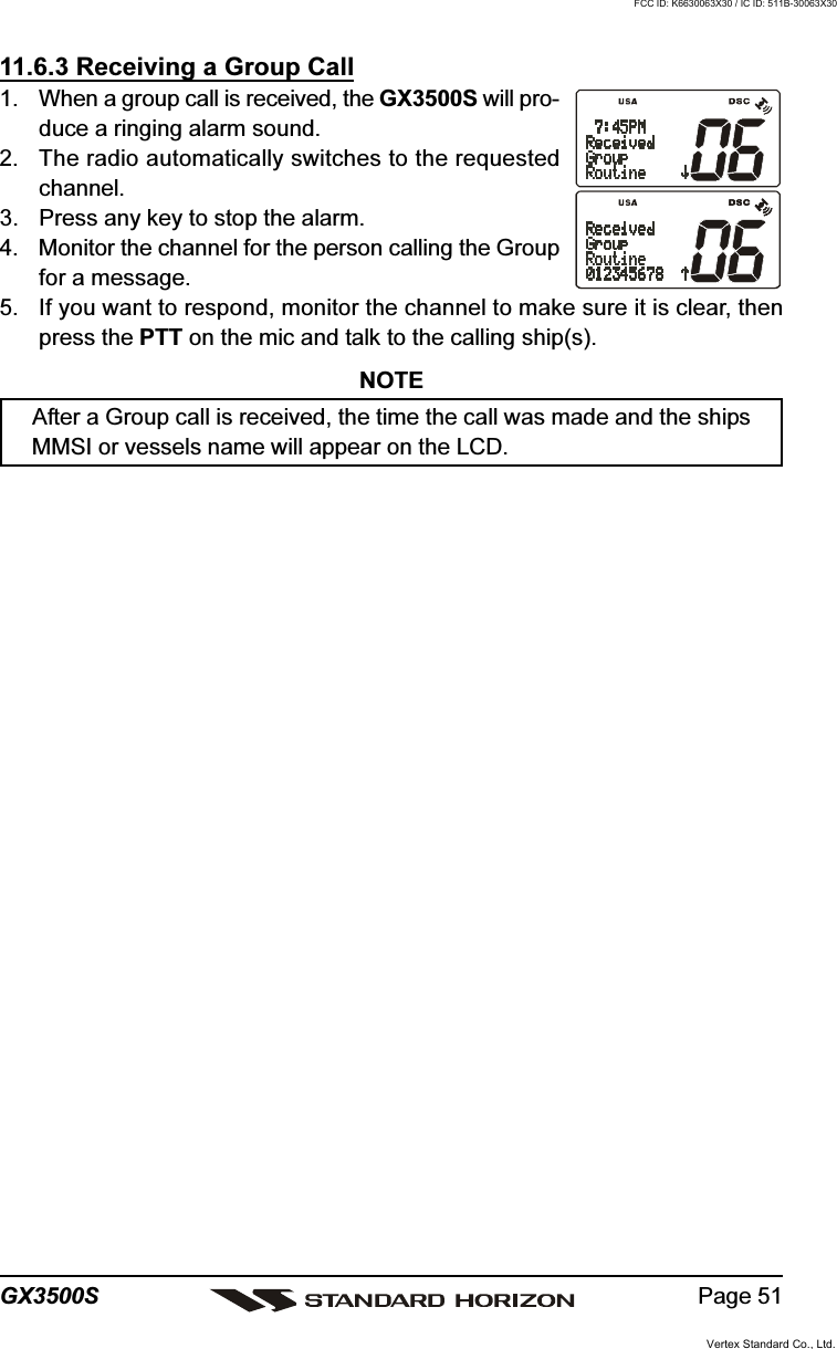
![Page 49GX3500Snumber entry.10. Enter the MMSI number by the keypad. If a mistakewas made entering in the number, press the [CLR]key to delete the wrong character.11. To enter the desired number and move one space tothe right press the [ENT] key. Repeat procedure until all nine spaces ofMMSI number are entered.12. If a mistake was made entering in the name or the MMSI number repeatpressing the [ENT] key until the wrong character is selected, then move theCHANNEL selector knob to correct the entry.13. To store the data entered, press and hold the [ENT] key.14. To enter another individual address, repeat steps 4 through 13.15. To exit this menu and return to radio operation mode press the [16/9] key.11.6.2 Transmitting a Group CallPre-Programmable Calling1. Press the [CALL(MENU)] key. The “DSC Operation”menu will appear.2. Turn the CHANNEL selector knob to select “Group.”(To cancel, select “Exit” with the CHANNEL selectorknob or press [16/9] key.)3. Press the [ENT] key. The transceiver will beep, andthe “Group Directory” will appear.4. Turn the CHANNEL selector knob to select the“Group” you want to contact.5. Press the [ENT] key, then turn the CHANNEL selec-tor knob to select the operating channel you want tocommunicate on and press the [ENT] key.6. Press the [ENT] key again to transmit the Group Callsignal.7. After the GROUP CALL is transmitted, all the radiosin the group will switch to the designated channel.8. Listen to the channel to make sure it is not busy, thenkey the microphone and call the other vessels youdesire to communicate with.Vertex Standard Co., Ltd.FCC ID: K6630063X30 / IC ID: 511B-30063X30](https://usermanual.wiki/Yaesu-Musen/30063X30/User-Guide-465253-Page-49.png)
![GX3500SPage 50Manual CallingYou may enter an MMSI number manually to contact without the Setting up theGroup call number.1. Press the [CALL(MENU)] key. The “DSC Operation”menu will appear.2. Turn the CHANNEL selector knob to select “Group.”(To cancel, select “Exit” with the CHANNEL selectorknob or press [16/9] key.)3. Press the [ENT] key. The transceiver will beep, andthe “Group Directory” will appear.4. Turn the CHANNEL selector knob to select “Manual,”then press the [ENT] key.5. Enter the MMSI number (eight digits) which you wantto contact by the keypad, then press the [ENT] key.6. Turn the CHANNEL selector knob to select “Manual,”then press the [ENT] key.7. Turn the CHANNEL selector knob to select the oper-ating channel which you want to communicate on,then press the [ENT] key.8. Press the [ENT] key again to transmit the Group Callsignal.9. After the GROUP CALL is transmitted, all the radiosin the group will switch to the designated channel.10. Listen to the channel to make sure it is not busy, thenkey the microphone and call the other vessels youdesire to communicate with.Vertex Standard Co., Ltd.FCC ID: K6630063X30 / IC ID: 511B-30063X30](https://usermanual.wiki/Yaesu-Musen/30063X30/User-Guide-465253-Page-50.png)
![GX3500SPage 5211.7 POSITION REQUESTAdvancements in DSC have made it possible to poll the location of anothervessel and show the position of that vessel on the display of the GX3500S.Standard Horizon has taken this feature one step further, if any Standard Hori-zon GPS is connected to the GX3500S, the polled position of the vessel isshown on the display of the GPS chart plotter making it easy to navigate to thelocation of the polled vessel. This is a great feature for anyone wanting to knowthe position of another vessel. For example your buddy that is catching fish, orfinding the location of a person you are cruising with.NOTEThe other vessel must have an operating GPS receiver connected to itsDSC transceiver and must not have its transceiver set to deny positionrequests. (Refer the section 11.5.1 to enter information into the indi-vidual directory).11.7.1 Setting up Position ReplyThe GX3500S can be set up to automatically or manually send your position toanother vessel. This selection is important if you are concerned about some-one polling the position of your vessel that you may not want to. In the manualmode you will see the MMSI or persons name shown on the display allowingyou to choose to send your position to the requesting vessel.1. Press and hold down the [CALL(MENU)] key until“Radio Setup” menu appear.2. Turn the CHANNEL selector knob to select “DSCSetup” menu.3. Press the [ENT] key, then select “POS Reply” withthe CHANNEL selector knob.4. Press the [ENT] key.5. Turn the CHANNEL selector knob to select “Auto”or “Manual.” In “Auto” mode, after a DSC POS Re-quest is received, the radio will automatically trans-mit your vessels position. In “Manual” mode, the dis-play of the GX3500S will show who is requesting theposition.6. Press the [ENT] key to store the selected setting.7. To exit this menu and return to radio operation mode press the [16/9] key.Vertex Standard Co., Ltd.FCC ID: K6630063X30 / IC ID: 511B-30063X30](https://usermanual.wiki/Yaesu-Musen/30063X30/User-Guide-465253-Page-52.png)
![Page 53GX3500SThe GX3500S has the capability to turn off the Position Request ringer.1. Press and hold down the [CALL(MENU)] key until“Radio Setup” menu appear.2. Turn the CHANNEL selector knob to select “DSCSetup” menu.3. Press the [ENT] key, then select “DSC Beep” with theCHANNEL selector knob.4. Press the [ENT] key.5. Turn the CHANNEL selector knob to select “POSRequest.”6. Turn the CHANNEL selector knob to select “Off.”7. Press the [ENT] key to store the selected setting.8. To exit this menu and return to radio operation modepress the [16/9] key.If you wish to return to enabling the ringer tone, just re-peat the above procedure, turning the CHANNEL selec-tor knob to select “On” in step “6” above.11.7.2 Transmitting a Position Request to Another VesselPre-Programmable Request1. Press the [CALL(MENU)] key. The “DSC Operation”menu will appear in the display.2. Turn the CHANNEL selector knob to select “POS Re-quest.”3. Press [ENT] key to show the Position request direc-tory. This directory uses the INDIVIDUAL Directoryinformation.4. Turn the CHANNEL selector knob to select a name,then press the [ENT] key.5. Press the [ENT] key to transmit the position requestDSC call.6. When the GX3500S receives the position from thepolled vessel it is shown on the radio display andalso transferred to the GPS Chart plotter.7. If the GX3500S does not receive a reply, the displaywill be as shown in the illustration on the right. Tosend again, press the [ENT] key.Vertex Standard Co., Ltd.FCC ID: K6630063X30 / IC ID: 511B-30063X30](https://usermanual.wiki/Yaesu-Musen/30063X30/User-Guide-465253-Page-53.png)
![GX3500SPage 54NOTEIf the GX3500S does not receive position data from the polled vessel,the LCD will show “NO POSITION DATA.”Manual RequestYou may enter an MMSI number manually to contact without the Setting up theIndividual / Position Call Directory.1. Press the [CALL(MENU)] key. The “DSC Operation”menu will appear in the display.2. Turn the CHANNEL selector knob to select “POS Re-quest.”3. Press [ENT] key to show the Position request direc-tory. This directory uses the INDIVIDUAL Directoryinformation.4. Turn the CHANNEL selector knob to select the“Manual,” then press the [ENT] key.5. Enter the MMSI number (eight digits) which you wantto contact by the keypad, then press the [ENT] key.6. Press the [ENT] key to transmit the position requestDSC call.7. When the GX3500S receives the position from thepolled vessel it is shown on the radio display andalso transferred to the GPS Chart plotter.8. If the GX3500S does not receive a reply, the displaywill be as shown in the illustration on the right. Tosend again, press the [ENT] key.Vertex Standard Co., Ltd.FCC ID: K6630063X30 / IC ID: 511B-30063X30](https://usermanual.wiki/Yaesu-Musen/30063X30/User-Guide-465253-Page-54.png)
![Page 55GX3500S11.7.3 Receiving a Position RequestWhen a position request call is received from another vessel, a ringing alarmwill sound and POS REQUEST will be show in the LCD. Operation and trans-ceiver function differs depending on “POS Reply” in the “DSC Setup” menusetting.Automatically reply:1. When a position request call is received, a calling alarm sounds 4 times.Then requested position coordinates are transmit-ted automatically to the vessel requesting your ves-sels position.2. To exit from position request display, press any key.Manually reply:1. When a position request call is received from an-other vessel, the LCD will be as shown in the illustra-tion at the right.2. A ringing alarm sounds 4 times. Then select type ofreply function “Send” or “No Reply” by using theCHANNEL selector knob.3. The GX3500S display will show “Send” or “No Re-ply” allowing you to send your vessels location byusing the CHANNEL selector knob.4. When “Send” is selected, press the [ENT] key. And your position will betransmitted to the requesting vessel.5. To exit from position request display, press the [16/9] key.Vertex Standard Co., Ltd.FCC ID: K6630063X30 / IC ID: 511B-30063X30](https://usermanual.wiki/Yaesu-Musen/30063X30/User-Guide-465253-Page-55.png)
![GX3500SPage 5611.8 POSITION SENDThe feature is similar to Position Request, however instead of requesting aposition of another vessel this function allows you to send your position to an-other vessel. Your vessel must have an operating GPS receiver connected forthe GX3500S to send the position.11.8.1 Setting up a Position Send RingerThe GX3500S has the capability to turn off the Position Send ringer.1. Press and hold down the [CALL(MENU)] key until“Radio Setup” menu appears.2. Turn the CHANNEL selector knob to select “DSCSetup” menu.3. Press the [ENT] key, then select “DSC Beep” with theCHANNEL selector knob.4. Press the [ENT] key.5. Turn the CHANNEL selector knob to select “POSSend.”6. Turn the CHANNEL selector knob to select “Off.”7. Press the [ENT] key to store the selected setting.8. To exit this menu and return to radio operation modepress the [16/9] key.If you wish to return to enabling the ringer tone, just re-peat the above procedure, turning the CHANNEL selec-tor knob to select “On” in step “6” above.Vertex Standard Co., Ltd.FCC ID: K6630063X30 / IC ID: 511B-30063X30](https://usermanual.wiki/Yaesu-Musen/30063X30/User-Guide-465253-Page-56.png)
![Page 57GX3500S11.8.2 Transmitting a DSC Position Send CallPre-Programmable Calling1. Press the [CALL(MENU)] key. The “DSC Operation”menu will appear in the display.2. Turn the CHANNEL selector knob to select the “POSSend.”3. Press the [ENT] key to select the Individual directory.4. Turn the CHANNEL selector knob to select a namein the directory, then press the [ENT] key.5. Press the [ENT] key to send your position to the se-lected vessel.Manual CallingYou may enter an MMSI number manually to contact without the Setting up theIndividual / Position Call Directory.1. Press the [CALL(MENU)] key. The “DSC Operation”menu will appear in the display.2. Turn the CHANNEL selector knob to select the “POSSend.”3. Press [ENT] key to show the Position Send directory.This directory uses the INDIVIDUAL Directory infor-mation.4. Turn the CHANNEL selector knob to select “Manual,”then press the [ENT] key.5. Enter the MMSI number (eight digits) which you wantto contact by the keypad, then press the [ENT] key.6. Press the [ENT] key to send your position to the se-lected vessel.Vertex Standard Co., Ltd.FCC ID: K6630063X30 / IC ID: 511B-30063X30](https://usermanual.wiki/Yaesu-Musen/30063X30/User-Guide-465253-Page-57.png)
![GX3500SPage 5811.8.3 Receiving a DSC Position Send CallWhen another vessel transmits their vessels location to the GX3500S the fol-lowing will happen:1. A ringing sound will be produced when the call is received.2. Press the [16/9] key to stop ringing3. The position from the vessel sending it's position will be shown on the dis-play of the radio and also transferred to any Standard Horizon GPS Chartplotter if connected.Vertex Standard Co., Ltd.FCC ID: K6630063X30 / IC ID: 511B-30063X30](https://usermanual.wiki/Yaesu-Musen/30063X30/User-Guide-465253-Page-58.png)
![Page 59GX3500S11.9 MANUAL INPUTTING OF THE GPS LOCATION (LAT/LON)You may send the Latitude/Longitude of your vessel manually even if theGX3500S is not connected the GPS receiver unit.After the position is entered, transmitting a DSC Distress, Position Request, orPosition Send will contain the manually entered position.1. Press and hold down the [CALL(MENU)] key until“Radio Setup” menu appears.2. Turn the CHANNEL selector knob to select “DSCSetup” menu.3. Press the [ENT] key, then select “POS Input” withthe CHANNEL selector knob.4. Press the [ENT] key. The transceiver will beep, andthe display will be as shown in the illustration on theright.5. Enter the your local time from the keypad by the 24-hour system on the UTC time, then press the [ENT]key.6. Enter the Latitude/Longitude of your vessel locationby the keypad, then press the [ENT] key. To selectNorth (N) press [6(NAV)] key, South (S) press the[7(SCRM)] key, East (E) press the [3(SCAN)] key orWest (W) press the [9(FOG)] key.7. To store the data entered, press the [16/9] key to exitthis menu and return to radio operation mode.Vertex Standard Co., Ltd.FCC ID: K6630063X30 / IC ID: 511B-30063X30](https://usermanual.wiki/Yaesu-Musen/30063X30/User-Guide-465253-Page-59.png)
![GX3500SPage 6012 RADIO SETUPNOTEThe optional RAM+ MIC CMP25 can also change the RADIO SETUPmenu. Refer to page 74 for details.12.1 LCD CONTRASTThis selection sets up the display for best viewabilty for the varying mountinglocations (overhead or below).1. Press and hold down the [CALL(MENU)] key until“Radio Setup” menu appears.2. Press the [ENT] key, then select “Contrast” in the“Radio Setup” menu with the CHANNEL selectorknob.3. Press the [ENT] key.4. Turn the CHANNEL selector knob to select the de-sired level. The contrast level can be set from “0” to“31.”5. Press the [ENT] key to store the selected level.6. To exit this menu and return to radio operation modepress the [16/9] key.Vertex Standard Co., Ltd.FCC ID: K6630063X30 / IC ID: 511B-30063X30](https://usermanual.wiki/Yaesu-Musen/30063X30/User-Guide-465253-Page-60.png)
![Page 61GX3500S12.2 TIME OFFSETThis selection sets the time offset between local time and UTC (time GPSsends to radio). Time is displayed when GPS position (LAT/LON) is displayedby pressing the [F] key followed by the [6(NAV)] key.1. Press and hold down the [CALL(MENU)] key until“Radio Setup” menu appears.2. Press the [ENT] key, then select “Time Set” in the“Radio Setup” menu with the CHANNEL selectorknob.3. Press the [ENT] key.4. Turn the CHANNEL selector knob to select time off-set from UTC. See illustration below to find your off-set time from UTC. If “0:00” is assigned, the time isthe same as UTC (Universal Time Coordinated orGMT Greenwich Mean Time).5. Press the [ENT] key to store the time offset.6. To exit this menu and return to radio operation mode press the [16/9] key.OFFSET TIME TABLEVertex Standard Co., Ltd.FCC ID: K6630063X30 / IC ID: 511B-30063X30](https://usermanual.wiki/Yaesu-Musen/30063X30/User-Guide-465253-Page-61.png)
![GX3500SPage 6212.3 TIME LOCATIONThis selection selects the time display between local time and UTC (time GPSsends to radio). Time is displayed when GPS position (LAT/LON) is displayedby pressing the [F] key followed by the [6(NAV)] key.1. Press and hold down the [CALL(MENU)] key until“Radio Setup” menu appears.2. Press the [ENT] key, then select “Time Disp.” in the“Radio Setup” menu with the CHANNEL selectorknob.3. Press the [ENT] key.4. Turn the CHANNEL selector knob to select “UTC” or“Local.”5. Press the [ENT] key to store the selected setting.6. To exit this menu and return to radio operation modepress the [16/9] key.n the local time mode, the display shows the time by the 12-hour system. Mean-while, the display shows the time by the 24-hour system in the UTC mode.12.4 TRUE MAGNETIC CHANGE (NAV display)This selection allows customizing the GPS COG (Course Over Ground) dis-played on the LCD to be in True or Magnetic.1. Press and hold down the [CALL(MENU)] key until“Radio Setup” menu appears.2. Press the [ENT] key, then select “Magnetic” in the“Radio Setup” menu with the CHANNEL selectorknob.3. Press the [ENT] key.4. Turn the CHANNEL selector knob to select “On” (rep-resenting “Magnetic”) or “Off” (representing “True”).5. Press the [ENT] key to store the selected setting.6. To exit this menu and return to radio operation modepress the [16/9] key.(“UTC” mode)(“LOCAL” mode)Vertex Standard Co., Ltd.FCC ID: K6630063X30 / IC ID: 511B-30063X30](https://usermanual.wiki/Yaesu-Musen/30063X30/User-Guide-465253-Page-62.png)
![Page 63GX3500S12.5 PRIORITY CHANNEL SETAllows selection of the priority channel.1. Press and hold down the [CALL(MENU)] key until“Radio Setup” menu appears.2. Press the [ENT] key, then select “Priority CH” in the“Radio Setup” menu with the CHANNEL selectorknob.3. Press the [ENT] key.4. Turn the CHANNEL selector knob to select the chan-nel to be a priority.5. Press the [ENT] key to store the selected setting.6. To exit this menu and return to radio operation modepress the [16/9] key.12.6 SCAN TYPEThis selection selects the scan mode between “Memory Scan” and “PriorityScan.”1. Press and hold down the [CALL(MENU)] key until“Radio Setup” menu appears.2. Press the [ENT] key, then select “SCAN Type” in the“Radio Setup” menu with the CHANNEL selectorknob.3. Press the [ENT] key.4. Turn the CHANNEL selector knob to select “Prior-ity” or “Memory.”5. Press the [ENT] key to store the selected setting.6. To exit this menu and return to radio operation modepress the [16/9] key.Vertex Standard Co., Ltd.FCC ID: K6630063X30 / IC ID: 511B-30063X30](https://usermanual.wiki/Yaesu-Musen/30063X30/User-Guide-465253-Page-63.png)
![GX3500SPage 6412.7 SCAN RESUME TIMEThis selection is used to select the time the GX3500S waits after a transmis-sion ends before starting scanning.1. Press and hold down the [CALL(MENU)] key until“Radio Setup” menu appears.2. Press the [ENT] key, then select “SCAN Resume” inthe “Radio Setup” menu with the CHANNEL selec-tor knob.3. Press the [ENT] key.4. Turn the CHANNEL selector knob to select the de-sired resume time. The resume time can be set to“1sec,” “2sec,” “3sec,” or “Off.” In the “Off” selec-tion, the scanner will resume after the other stationstops transmitting (carrier drops).5. Press the [ENT] key to store the selected setting.6. To exit this menu and return to radio operation mode press the [16/9] key.12.8 KEY BEEP (ON/OFF)This selection allows the beep tone when a key is pressed to be turned off.1. Press and hold down the [CALL(MENU)] key until“Radio Setup” menu appears.2. Press the [ENT] key, then select “Key Beep” in the“Radio Setup” menu with the CHANNEL selectorknob.3. Press the [ENT] key.4. Turn the CHANNEL selector knob to select “On” or“Off.”5. Press the [ENT] key to set the key beep condition.6. To exit this menu and return to radio operation modepress the [16/9] key.NOTEEmergency alarm and beeps for DSC operation cannot be turned OFF.Vertex Standard Co., Ltd.FCC ID: K6630063X30 / IC ID: 511B-30063X30](https://usermanual.wiki/Yaesu-Musen/30063X30/User-Guide-465253-Page-64.png)
![Page 65GX3500S12.9 WX ALERTThis selection allows the radios NOAA Weather alert to be turned off. Defaultsetting is ON.1. Press and hold down the [CALL(MENU)] key until“Radio Setup” menu appears.2. Press the [ENT] key, then select “WX Alert” in the“Radio Setup” menu with the CHANNEL selectorknob.3. Press the [ENT] key.4. Turn the CHANNEL selector knob to select the de-sired WX alert mode. The WX alert mode can be setto “On WX,” “On SCAN,” “On SCAN/WX,” or “Off.”5. Press the [ENT] key to store the selected setting.6. To exit this menu and return to radio operation modepress the [16/9] key.Vertex Standard Co., Ltd.FCC ID: K6630063X30 / IC ID: 511B-30063X30](https://usermanual.wiki/Yaesu-Musen/30063X30/User-Guide-465253-Page-65.png)
![GX3500SPage 6612.10 CHANNEL NAME CHANGEThis selection allows you to customize the name of a channel from the defaultname.1. Press and hold down the [CALL(MENU)] key until“Radio Setup” menu appears.2. Press the [ENT] key, then select “CH Name” in the“Radio Setup” menu with the CHANNEL selectorknob.3. Press the [ENT] key.4. Turn the CHANNEL selector knob to select the chan-nel to be named, then press the [ENT] key.5. Press the one of the Keypad keys to enter the firstletter of the channel name.Example: Press the [2(MEM)] key repeatedly to toggleamong the seven available charactors associatedwith that key: A B C a b c 2.6. Press the [ENT] key to enter the desired letter andmove the cursor one space to the right.7. Repeat procedure until the name is complete. Thename can consist of up to twelve characters. If youdo not use all twelve character, press the [ENT] keyto move to the next space. To clear the previous let-ter, press the [H/L(NAV)] key.8. Press and hold the [ENT] key to enter the name and exit from the “CHName” menu. The LCD will return to the “Radio Setup” menu.9. If you want to enter the name of another channel, repeat steps 3 through 8.10. To exit this menu and return to radio operation mode press the [16/9] key.Vertex Standard Co., Ltd.FCC ID: K6630063X30 / IC ID: 511B-30063X30](https://usermanual.wiki/Yaesu-Musen/30063X30/User-Guide-465253-Page-66.png)
![Page 67GX3500S12.11 NAMING THE RADIO OR RAM+ STATIONSThis selection allows you to provide the name to the radio and optional RAM+Mic’s when connected.1. Press and hold down the [CALL(MENU)] key until“Radio Setup” menu appears.2. Press the [ENT] key, then select “Unit Name” in the“Radio Setup” menu with the CHANNEL selectorknob.3. Press the [ENT] key.4. Turn the CHANNEL selector knob to select the Unit(Radio, RAM 1, or RAM2) to be named, then pressthe [ENT] key.5. Press the one of the Keypad keys to enter the firstletter of the unit name.Example: Press the [2(MEM)] key repeatedly to toggleamong the seven available charactors associatedwith that key: 2 A B C a b c.6. Press the [ENT] key to enter the desired letter andmove the cursor one space to the right.7. Repeat procedure until the name is complete. Thename can consist of up to twelve characters. If youdo not use all twelve character, press the [ENT] keyto move to the next space.8. Press and hold the [ENT] key to enter the name andexit from the “Unit Name” menu. The LCD will return to the “Radio Setup”menu.9. If you want to enter the name of another unit, repeat steps 3 through 8.10. To exit this menu and return to radio operation mode press the [16/9] key.Vertex Standard Co., Ltd.FCC ID: K6630063X30 / IC ID: 511B-30063X30](https://usermanual.wiki/Yaesu-Musen/30063X30/User-Guide-465253-Page-67.png)
![GX3500SPage 6812.12 FOG ALERT TONE FREQUENCYThis selection allows you to select the Alert Tone Frequency for the PA/FOGOperation. Available selections are “200 Hz” through “850 Hz” in 50 Hz steps.The default Alert Tone Frequency is 400 Hz.1. Press and hold down the [CALL(MENU)] key until“Radio Setup” menu appear.2. Press the [ENT] key, then select “Fog Freq.” in the“Radio Setup” menu with the CHANNEL selectorknob.3. Press the [ENT] key.4. Turn the CHANNEL selector knob to select desiredtone frequency.5. Press the [ENT] key to store the selected setting.6. To exit this menu and return to radio operation modepress the [16/9] key.Vertex Standard Co., Ltd.FCC ID: K6630063X30 / IC ID: 511B-30063X30](https://usermanual.wiki/Yaesu-Musen/30063X30/User-Guide-465253-Page-68.png)
![Page 69GX3500S13 ENHANCED RAM+ MIC OPERATIONWhen the RAM+ microphone is connected to the GX3500S, most VHF, DSC,setup menus and PA modes can be remotely operated. The RAM+ Mic sup-plied with 23 feet (7 m) of routing cable and can be extended up to 70 feet (21m) using three 23 feet extension cables model CT-100. The intercom operationcan be used between the RAM+ Mic and the transceiver.13.1 RAM+ MIC CONTROLSSQUELCH CONTROL (SQL)Activates the squelch adjusting mode.Press this key to activate the squelch adjusting mode. Press themicrophone’s [] or [] key to adjust the squelch.When this key is pressed and held down for 1 second or more, the squelchis turned off.VOLUME KEY (VOL)Activates the volume adjusting mode.Press this key to activate the volume adjusting mode. Press themicrophone’s [] or [] to adjust the volume.SCAN DWNAVWXCALLSETME M ICU.I.CMENU169Vertex Standard Co., Ltd.FCC ID: K6630063X30 / IC ID: 511B-30063X30](https://usermanual.wiki/Yaesu-Musen/30063X30/User-Guide-465253-Page-69.png)
![GX3500SPage 70POWER SWITCH (PWR)Press and hold down this key to turn to the transceiver and RAM+ Mic onand off.PTT (Push-To-Talk) SWITCHActivates transmission.[H/L] KEYToggles between high and low power. When the [H/L] key is pressed whilethe transceiver is on channel 13 or 67, the power will temporarily switchfrom LO to HI power until the PTT is released. The [H/L] key does notfunction on transmit inhibited and low power only channels.[](UP)/[](DOWN) KEYThese keys are used to select channels, adjust the volume and squelchlevel, and to choose the item selection of different functions (such as theDSC operation). In many ways, these keys emulate the function of thetransceiver’s CHANNEL selector knob.[16/9] KEYImmediately recalls channel 16 from any channel location. Holding downthis key recalls channel 9. Pressing the [16/9] key reverts to the previousselected working channel.Secondary usePlease see secondary use for the [WX] and [MEM] key.KEY PAD[SCAN] Key1. Starts and stops scanning of programmed channels.2. If held while the [UP()] or [DOWN()] key on the microphone arepressed, the radio will show the channels programmed in scanmemory. This function will not work if the unit is scanning.NOTE: The priority channel by default is Channel 16, however thepriority channel can be changed. To select a different priority channelrefer to section “12.6 SCAN TYPE.”[CALL/SET] KeyThe [CALL/SET] key functions as the enter key.Secondary usePress the [CALL/SET] key to access the DSC OPERATION menu.Press and hold the [CALL/SET] key to access the SETUP menu.Vertex Standard Co., Ltd.FCC ID: K6630063X30 / IC ID: 511B-30063X30](https://usermanual.wiki/Yaesu-Musen/30063X30/User-Guide-465253-Page-70.png)
![Page 71GX3500S[DW] KeyWatches for a transmission on CH16 and another selected channel untileither signal is received. (Dual watch)Secondary usePress and hold [DW] key, intercom operation will operate between radioand RAM+ Mic.[NAV] KeyPress this key, when connected to the GPS receiver, the LCD displaysPosition Data and Time from the GPS.Secondary usePress and hold [NAV] key to access PA/FOG function menu.[WX] KeyImmediately recalls the previously selected US NOAA weather channel fromany channel location.Secondary useHolding down the [16/9] key while pressing the [WX] key switch the Chan-nel Group.NOTE: If position is displayed, this icon will be hidden.[DISTRESS] KEYUsed to send a DSC Distress Call. To send the distress call:1. Lift the red rubber cover.2. Press and hold the Red button. The RAM+ display will count down (3-2-1) and then transmit the Distress call.3. When the distress signal is sent, Ch70 and “ ” icon will appear onthe LCD. After the message has been sent, the radio and RAM+ willsound a Distress Alarm.4. The transceiver “shadow-watches” for a transmission onCH16 or CH70 until an acknowledgment signal is re-ceived. “DISTRESS” and “WAITING” will appear on theLCD.5. If an acknowledgement is received, select channel 16and advise your distress situation.6. If no acknowledgment is received, the distress call isrepeated in 4 minute intervals until an acknowledgmentis received.7. When a DSC Distress acknowledgment is received, adistress alarm sounds and channel 16 is automaticallyselected. The LCD shows the MMSI of the ship responding to your dis-tress.Vertex Standard Co., Ltd.FCC ID: K6630063X30 / IC ID: 511B-30063X30](https://usermanual.wiki/Yaesu-Musen/30063X30/User-Guide-465253-Page-71.png)
![GX3500SPage 72RECEIVED ACK: acknowledgment signal is received.RECEIVED RLY: relay signal is received from another vessel or coaststation.8. To cancel the DSC distress alarm signal from the speaker, press anykey.13.2 INTERCOM OPERATION13.2.1 Communication1. Press and hold the [DW] key while in the “RADIO” mode, the mode ischanged to “INTERCOM” mode.2. If your GX3500S is equipped with two RAM+ Mic, select the companion youwish to communicate (RADIO, RAM, or ALL) with the []/[] key, thenpress the [CALL/SET] key.3. When the “INTERCOM” operation is activated, “IC” is dis-played on the RAM+ Mic and “INTERCOM” is displayed onthe GX3500S.4. Press the PTT switch, “TALK” is displayed.NOTE: A warning beep is emitted when the RAM+ Mic PTT switch is pressedwhile the transceiver microphone’s PTTswitch is pressed.5. Speak slowly and clearly into the mi-crophone, hold the microphone about1/2 inch away from your mouth.6. When finished, release the PTT switch.7. Press the [DW] key again the mode willrevert to “RADIO” mode.13.2.2 CallingHold down the [DW] key for 1 second or more, when the “INTERCOM” opera-tion is activated. A calling beep is emitted twice from the transceiver speaker.(RAM+ Mic’s PTT switch is pressed)(GX3500S’s PTT switch is pressed)Vertex Standard Co., Ltd.FCC ID: K6630063X30 / IC ID: 511B-30063X30](https://usermanual.wiki/Yaesu-Musen/30063X30/User-Guide-465253-Page-72.png)
![Page 73GX3500S13.3 PA/FOG OPERATIONThe RAM+ is capable of controlling the 30W Public address, 4 fog horns, bellsand whistles.13.3.1 Operating the PA / Hailer1. Press and hold the [NAV] key then select PA with the [] or[] key.2. Press the [CALL/SET] key.3. Press the PTT switch and speak into the microphone.4. To turn up the PA Volume, press the PTT switch and pressthe [] or [] keys to adjust the Audio output level. Thelevel can be set from 0 to 30W.5. To adjust the listen back volume, (while in listenback mode)press the [VOL] Key, then press the [] or [] key to thedesired listen back volume.To exit from the PA Hailer mode, press the [CALL/SET], [16/9],or [WX] key.13.3.2 Operating the FOG HornThe GX3500S is capable of sending Underway, Stop, Sail, Tow, Horn, Siren,Aground and Anchor signals.1. Press and hold the [NAV] key then select FOG with the []or [] key.2. Press the [CALL/SET] key.3. Select the one of the eight functions described above withthe [] or [] key and press the [CALL/SET] key.4. On the “Horn” and “Siren” modes, press the PTT switch toactivate the tone through the HAIL/PA speaker.Press the [] or [] keys to adjust the Audio output level.The level can be set from 0 to 30W.5. To adjust the listen back volume, (while in listenback mode)press the [VOL] Key, then press the [] or [] key to thedesired listen back volume.To exit from the FOG HORN mode, press the [16/9], [WX], or[CALL/SET] key.Vertex Standard Co., Ltd.FCC ID: K6630063X30 / IC ID: 511B-30063X30](https://usermanual.wiki/Yaesu-Musen/30063X30/User-Guide-465253-Page-73.png)
![GX3500SPage 7413.4 DSC/RADIO SETUP MODEThe RAM+ can access the DSC / RADIO setup menu (refer to section “10DIGITAL SELECTIVE CALLING” and section “12 RADIO SETUP” for details).The LAMP, CONTRAST, and KEY BEEP menu item accessed from the RAM+only controls the RAM+’s display and speaker.DSC/RADIO Setup mode from the RAM+:1. Press and hold down the [CALL/SET] key until “RADIO SETUP” menu ap-pears.2. Press the []/[] key to select “RADIO SETUP” or “DSC SETUP” menu.3. Press the [CALL/SET] key, then select the menu item you wish to work onby pressing the []/[] key.4. Press the [CALL/SET] key.5. Press the []/[] key to change the value or condition for the menu item,then press the [CALL/SET] key to save the new setting.6. Press the []/[] key to select “EXIT,” then press the [CALL/SET] key toreturn to the normal operation.RADIO SETUP-menu DSC SETUP-menuVertex Standard Co., Ltd.FCC ID: K6630063X30 / IC ID: 511B-30063X30](https://usermanual.wiki/Yaesu-Musen/30063X30/User-Guide-465253-Page-74.png)