Yaesu Musen 30083220 VHF FM Marine Transceiver User Manual Operating manual
Yaesu Musen Co., Ltd. VHF FM Marine Transceiver Operating manual
UserManual.wiki
>
Yaesu Musen
>
30083220 User Manual
>
Operating manual
Contents
1.
Operating manual
2.
Revised User Manual
Operating manual
Navigation menu
Upload a User Manual
Namespaces
Wiki Guide
HTML
PDF
Info
Views
User Manual
Discussion / Help
Navigation
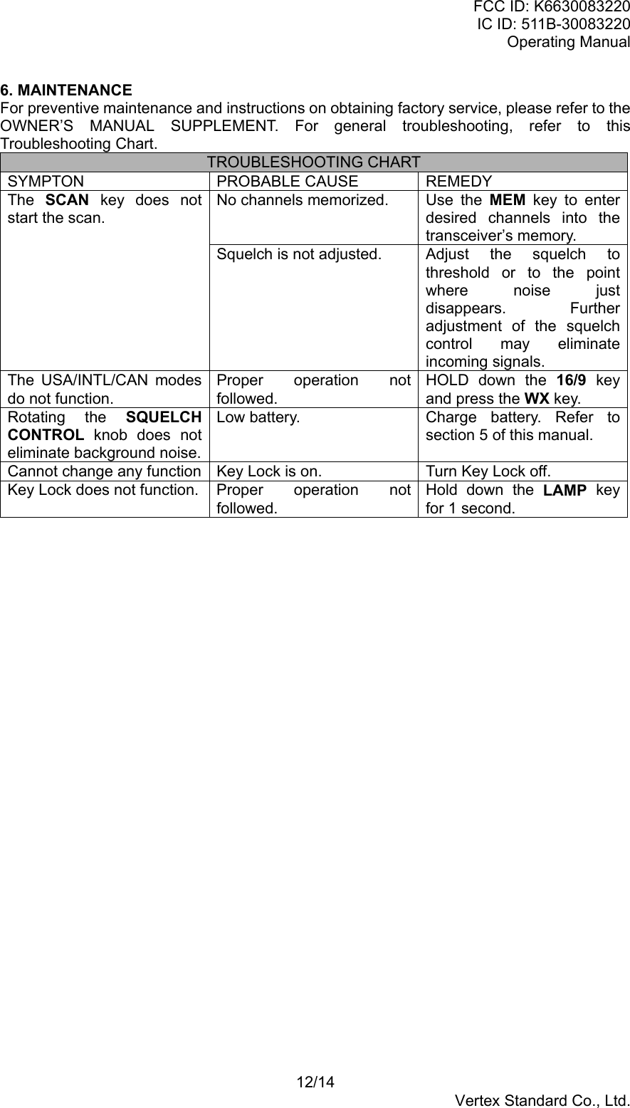
![FCC ID: K6630083220IC ID: 511B-30083220Operating Manual6/14Vertex Standard Co., Ltd.4. OPERATION4.1 INITIAL PROCEDURENOTE: Never key the transceiver without an antenna connected. Damage may occur to thetransceiver. Do not operate the transceiver while charging.1. Install the belt clip on the transceiver if desired. Use the one Phillips-head screwsincluded with the clip to mount the clip to the back of the transceiver.2. Install the nylon carrying strap on the belt clip if desired.3. Install the battery pack on the transceiver (see figure X and section 5.1)4. Install the antenna to the transceiver.5. Turn the POWER/VOLUME CONTROL knob clockwise to turn the transceiver.NOTE: Water resistance of the transceiver is assured only when the battery pack andantenna are attached to the transceiver.4.2 RESEPTION1. Turn the POWER/VOLUME CONTROL knob clockwise to turn the transceiver on.2. Turn up the POWER/VOLUME CONTROL knob until the noise or audio from thespeaker is at a desired level.3. Select a channel that has no signal being received (no one is transmitting on thechannel) and only noise heard.4. Press the SQ key. Then press [UP] or [DOWN] key and stop immediately after the noisedisappears. This condition is known as the “Squelch Threshold.” If the knob is turnedclockwise past this point, weak signals may not be received. No noise or no signal isheard until a signal is received that exceeds the squelch threshold.5. To change channel, press the [UP] or [DOWN] key. Sometimes, a slight adjustment ofthe squelch threshold is needed as some channels have a higher noise level thanothers.6. Please refer to the Owner’s Manual Supplement for a complete listing of all USA,International and Canadian VHF Marine channels and their use.4.3 TRANSMISSION1. Perform steps 1 through 7 of RECEPTION.2. Before transmitting, monitor the channel and make sure it is clear.THIS IS AN FCC REQUIREMENT!3. For communications over short distances, press the H/L key until “L” is displayed on theLCD. This indicates low power, approximately 1 watt.4. Note: Transmitting on 1 watt prolongs battery life. Low power (1 watt) should beselected whenever possible.5. If using low power is not effective, select mid power (2.5 watts) or high power (5 watts)by pressing the H/L key until “M” (mid power) or “H” (high power) is displayed.6. When receiving a signal, wait until the signal stops before transmitting. The transceivercannot transmit and receive simultaneously.7. Press the PTT (push-to-talk) switch. The “TX” indicator is displayed duringtransmission.8. Speak slowly and clearly into the microphone. Hold the microphone about 1/2 to 1 inchaway from your mouth.9. When the transmission is finished, release the PTT switch.10. Refer to the OWNWER’S MANUAL SUPPLEMENT for standard transceiver operatingprocedures.](https://usermanual.wiki/Yaesu-Musen/30083220.Operating-manual/User-Guide-416977-Page-6.png)
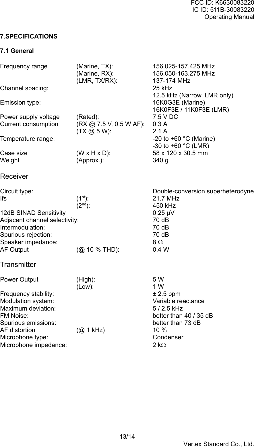
![FCC ID: K6630083220IC ID: 511B-30083220Operating Manual7/14Vertex Standard Co., Ltd.4.4 TRANSMIT TIME - OUT TIMER (TOT)While the PTT switch is held down, transmission time is limited to 5 minutes. This preventsprolonged unintentional transmissions. About 10 seconds before automatic transmittershutdown, a warning beep is sounds from speaker. The transceiver automatically switchesto the receiving mode, even if the PTT switch is held down. Before transmitting again, thePTT switch must first be released and press again. This time-out timer (TOT) prevents acontinuous transmission that would result from an accidentally stuck PTT switch.4.5 USA, CANADIAN, AND INTERNATIONAL MODES1. To change the mode of the transceiver, Held down the 16/9 key and press the WX key.The mode changes from USA, to International, to Canadian with each press.2. “USA” appear on the LCD for the USA mode, “CAN” appears for Canadian mode, and“INTL” appears in International mode.3. Refer to marine channel charts in OWNER’S MANUAL SUPPLEMENT for allocatedchannels in each mode.4.6 NOAA WEATHER CHANNELS1. To receive a weather channel, press the WX key. The transceiver changes to theweather channel mode.2. Press the [UP] or [DOWN] key to change to other weather channels.3. To exit from the weather channels, press the WX key. The transceiver recalls theprevious non-weather channel.4.7 SCAN1. Select the desired channel to be scanned using the [UP] or [DOWN] key.2. Press the MEM key to store the channel into the transceiver’s memory. “MEM” isdisplayed on the LCD.3. Repeat steps 1 and 2 for all the channels to be scanned.4. To delete a channel from the transceiver’s scan memory, press the MEM key againwhile the memorized channel is displayed. “MEM” disappears.5. All channels programmed remain in the transceiver’s scan memory even if the power isturned off. See section “4.17 RESETTING THE TRANSCEIVER’SMICROPROCESSOR” to clear all the transceiver’s scan memory.6. Adjust the SQUELCH CONTROL knob until background noise is eliminated.7. To start scan, press the SCAN key. The scan proceeds from the lowest to the highestprogrammed channel number and stops on channels when a transmission is received.8. To stop the scan, press the SCAN key.4.8 PRIORITY SCAN1. The following channels can be set as the priority channel; 16, 09, and Preset Channels1 through 5 (Preset Channel described section 4.14). To set the priority channel, holddown the 16/9 key and press the MEM key. The channel changes from 16 to 09 toPreset 1 to Preset 2 to Preset 3 to Preset 4 to Preset 5 channel with each press of theMEM key. The displayed channel is set to the priority channel.2. For priority scanning, hold down the SCAN key at least 1 second during normalscanning. Scanning will proceed between the memorized channels and the prioritychannel. The priority channel will be scanned after each programmed channel.3. For example, channels 06, 07, 08 are memorized in the transceiver’s memory, Priorityscanning will proceed in the following sequence:[CH06] Æ [Priority Channel] Æ [CH07] Æ [Priority Channel] Æ [CH08] Æ [PriorityChannel] Æ[CH06] Æ [Priority Channel] ………4. Even when the transceiver stops and listens to the signal of a programmed channel, thetransceiver will dual watch between this channel and the priority channel.](https://usermanual.wiki/Yaesu-Musen/30083220.Operating-manual/User-Guide-416977-Page-7.png)
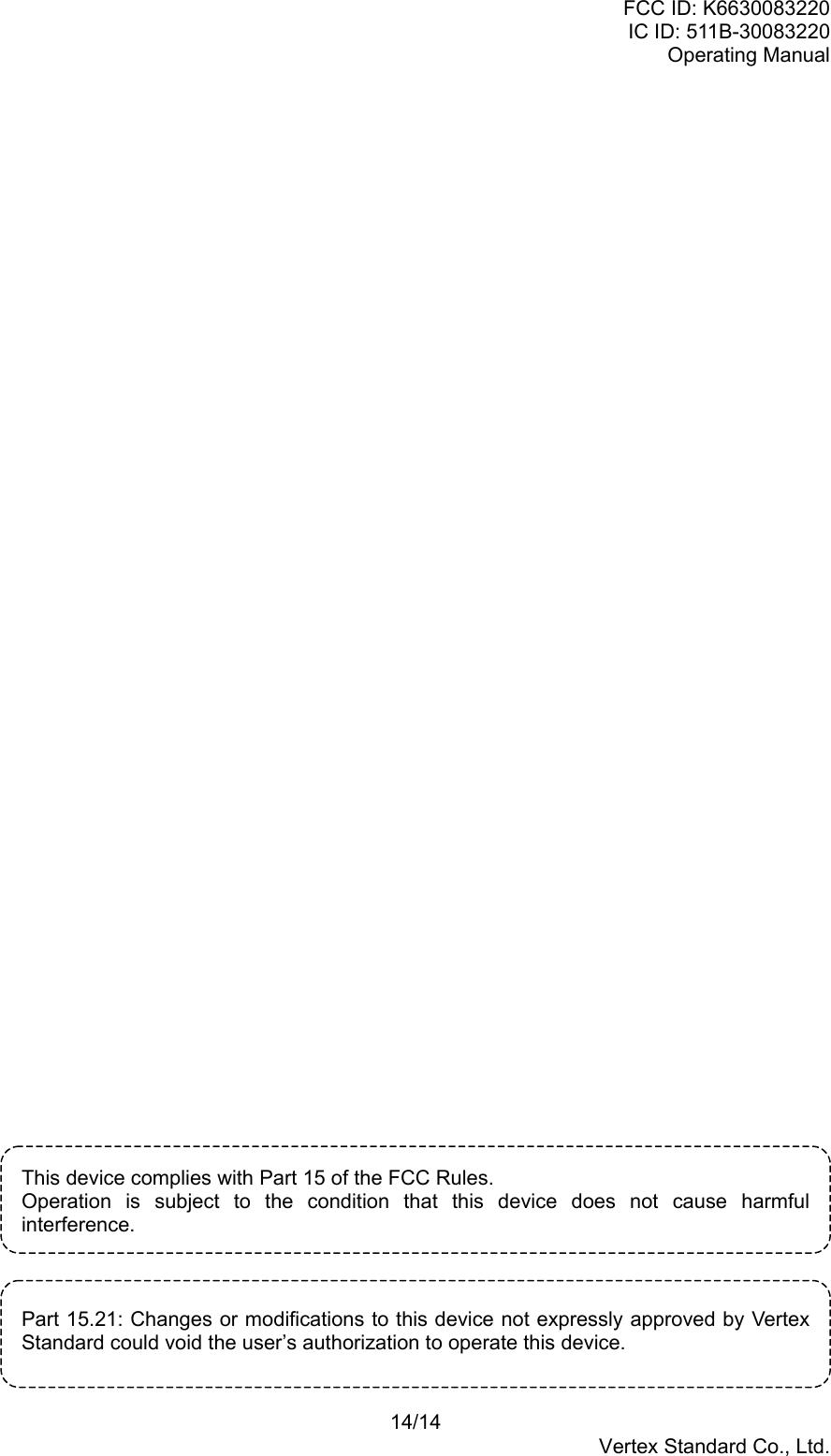
![FCC ID: K6630083220IC ID: 511B-30083220Operating Manual8/14Vertex Standard Co., Ltd.4.9 WEATHER ALERTIn the event of extreme weather disturbances such as storms and hurricanes, NOAA(National Oceanic and Atmospheric Administration) sends a weather alert accompanied bya 1050 Hz tone and subsequent weather reports on the weather channels. The transceiveris capable of receiving this alert if the following is performed:1. Program weather channels into the transceiver’s memory for scanning. Follow thesame procedure as for regular channels under Section 4.7.2. Press the SCAN key to start the scan.3. The memorized weather channels are scanned along with the regular memorizedchannels. Scan does not stop for normal weather broadcast.4. When an alert is received on a weather channel, scanning stops and the transceiverenters the WEATHER ALERT MODE.5. When the transceiver is in the WEATHER ALERT MODE, a loud tone is sounded.6. Press the WX key to stop the alert tone and receive the voice information on theweather channel.4.10 EMERGENCY CHANNEL 161. To select the emergency channel, press the 16/9 key from any channel.2. Transmit your emergency signal in the same manner as on regular channels. If you cannot contact anyone on channel 16, switch to another channel.3. See the OWNER’S MANUAL SUPPLEMENT for additional emergency operatingpractices.4. To recall the previous channel from 16, press the 16/9 key.4.11 CHANNEL 9Channel 9 is used as a hailing channel for initial, non-emergency contact with other vessels.Hold down the 16/9 key for 1 second to select channel 9.4.12 OPERATING ON CHANNEL 13Channel 13 is used at docks, bridges and for maneuvering in port. Messages on thischannel must concern navigation only, such as meeting and passing in restricted waters.In emergencies and when approaching blind river bends, high power is allowed. Hold downthe H/L key to temporarily switch to high or mid power. High or mid power can only beaccessed in USA and Canadian modes. When the PTT switch released, the transceiver willrevert low power.4.13 OPERATING ON CHANNEL 67When channel 67 is used for navigational bridge-to-bridge traffic between ships, high or midpower may be used temporarily in the USA mode by pressing the H/L key. When the PTTswitch released, the transceiver will revert low power.4.14 PRESET CHANNEL (A ~ E) INSTANT ACCESSFive user-assigned channels can be programmed for instant access. USA channel 70 andweather channels should not be assigned into the preset channels. If the PRESET key ispressed and no channels has been assigned, an alert signal will be emitted twice.4.14.1 ProgrammingHold down the PRESET key and press the [UP] or [DOWN] key until the desired channelnumber is displayed.With the desired channel number displayed, release the PRESET key. The “A” will appearon the display, indicating that the displayed channel is now designated PresetChannel A.Repeat steps 1 and 2 to program the desired channel to the Preset Channels b ~ E.To delete the Preset Channel, hold down the PRESET key and press the [UP] or [DOWN]](https://usermanual.wiki/Yaesu-Musen/30083220.Operating-manual/User-Guide-416977-Page-8.png)
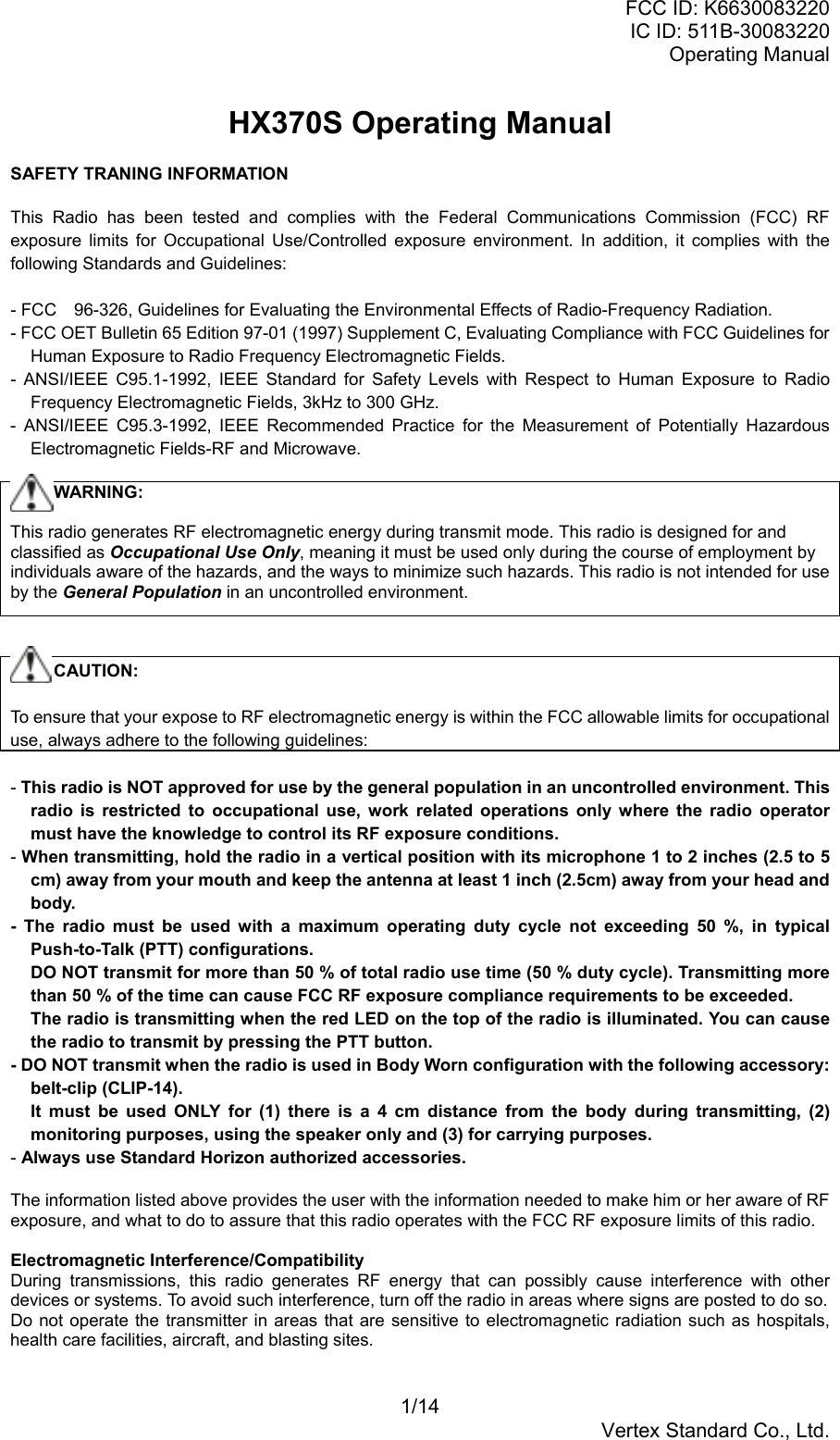
![FCC ID: K6630083220IC ID: 511B-30083220Operating Manual9/14Vertex Standard Co., Ltd.key until the Preset Channel number to be deleted is displayed, then release thePRESET key.4.14.2 OperationPressing the PRESET key toggles between Preset Channel A, b, C, d, E, and regularchannel. Preset Channel A is represented by “A” to the left of the channel number on theLCD, and channel B is represented by “b” ……. Do not confuse this “A” with the one thatsometimes is displayed to the right of the channel number (described in the section 3.2 ofthis Owner’s Manual).4.15 SIMPLEX/DUPLEX CHANNEL USEAll channels are factory-programmed in accordance with FCC (USA), Industry Canada andInternational regulations. Mode of operation cannot be altered from simplex to duplex orvice-versa. Simplex or duplex mode is automatically activated, depending on the channeland whether USA, International or Canadian operating mode is selected. Refer to thechannel charts in the OWNER’S MANUAL SUPPLEMENT.4.16 SET MODEThe HX370S’s Set Mode system allows a number of transceiver operating parameters to becustom-configured for your operating requirements.The Set Mode is easy to activated and set, using the following procedure:1. Turn the radio off.2. Hold down the SQ switch and then turn on the transceiver.3. The “SET” will appear on the display, indicate that activate the Set Mode.4. Press the SQ switch to select the Menu item to be adjusted.5. Press the [UP] or [DOWN] key select the status or value of the Menu item. Then pressSQ switch to save the new setting.6. After completing your adjustment, press the PTT switch to save the new setting and exitto normal operation.4.16.1 bEP (Key Beep)Function: Enable/disable Keypad beeper.Available Values: ON/OFFDefault: ON4.16.2 CHF (Channel Frequency Display)Function: Select the frequency of each channel.Available Values: ON/OFFDefault: OFF4.16.3 CHn (Channel Name)Function: Input channel name of each channel.Available Values: AlphanumericDefault:4.16.4 dUL (Dual Watch)Function: Select the Dual Watch channel.Available Values: SPL/NORDefault: SPL4.16.5 LP (Lamp Mode)Function: Select the LCD/Keypad Lamp mode.Available Values: KEY/CNT (Continuous)/OFF](https://usermanual.wiki/Yaesu-Musen/30083220.Operating-manual/User-Guide-416977-Page-9.png)
![FCC ID: K6630083220IC ID: 511B-30083220Operating Manual11/14Vertex Standard Co., Ltd.battery downward and out from the transceiver.3. To install, insert the battery pack into the battery compartment on the back of thetransceiver, then close the Battery Pack Latch until it locks in place with a “click.”5.2 FBA-25 BATTERY CASEFBA-25 is a battery case that holds two alkaline batteries and is used with the HX370Stransceiver. Alkaline batteries can be used for transmission in an emergency, but poweroutput will only be 0.9 W, and battery life will be shortened dramatically.1. Slide the batteries into the FBA-25 with the Negative [–] side of the batteries touching thespring connections inside the FBA-25.2. Insert the FBA-25 into the battery compartment on the back of the transceiver, then closethe Battery Pack Latch until it locks in place with a “click.”Note: The battery indicator on the transceiver is only applicable to the FNB-83/FNB-V57ISrechargeable battery. Disregard this indication when using alkaline batteries.5.5 BATTERY SAFETYBattery packs for your transceiver contains Nickel-Metal Hydride (Ni-MH, FNB-83) orNickel-cadmium (Ni-Cd, FNB-V57IS) batteries. This type of battery stores a charge powerfulenough to be dangerous if misused or abused, especially when removed from thetransceiver. Please observe the following precautions:DO NOT SHORT BATTERY PACK TERMINALSShorting the terminals that power to the transceiver can cause sparks, severe overheating,burns, and battery cell damage. If the short is of sufficient duration, it is possible to meltbattery components. Do not place a loose battery pack on or near metal surfaces or objectssuch as paper clips, keys, tools, etc. When the battery pack is installed on the transceiver,the terminals that transfer current to the transceiver are not exposed. The terminals that areexposed on the battery pack when it is mounted on the transceiver are charging terminalsonly and do not constitute a hazard.DO NOT INCINERATEDo not dispose of any Ni-MH or Ni-Cd battery in a fire or incinerator. The heat of fire maycause battery cells to explode and/or release dangerous gases.DISPOSE OF BATTERY PACKS PROPERLYNi-MH or Ni-Cd batteries must be recycled or disposed of properly. For requirements in yourarea, check with the dealer from whom you purchased your transceiver. The symbol shownbelow is a reminder that the battery packs are recyclable.](https://usermanual.wiki/Yaesu-Musen/30083220.Operating-manual/User-Guide-416977-Page-11.png)