Yaesu Musen 30083220 VHF FM Marine Transceiver User Manual HX370S new P65
Yaesu Musen Co., Ltd. VHF FM Marine Transceiver HX370S new P65
UserManual.wiki
>
Yaesu Musen
>
30083220 User Manual
>
Revised User Manual
Contents
1.
Operating manual
2.
Revised User Manual
Revised User Manual
Navigation menu
Upload a User Manual
Namespaces
Wiki Guide
HTML
PDF
Info
Views
User Manual
Discussion / Help
Navigation

![HX370SPage 165.2 RECEPTION1. Turn the POWER/VOLUME CONTROL knob clockwise to turn the trans-ceiver on.2. Press the SQL key, then press the [] key until theSQL level is 00.3. Turn up the POWER/VOLUME CONTROL knob un-til the noise or audio from the speaker is at a comfortable level.4. Select a channel that has no signal being received (no one is transmit-ting on the channel) and where only noise is heard.5. Press the SQL key, then press the [] key and stop immediately afterthe noise disappears. This condition is known as the “Squelch Thresh-old.” If the squelch is set to a higher level, weak signals may not bereceived.6. To change channels, press the [] or [] key.7. The LCD and keypad are illuminated for 5 seconds when any key ispressed. The lamp automatically turns off in 5 seconds.8. To “lock” the channel so that it is not accidentally changed, hold downthe H/L key for about one second. This locks the [] and [] buttonsand all the front panel controls except the H/L, PTT and SQL keys. The“” symbol will appear on the display to indicatethat the keypad is locked. Hold down the H/L key forabout one second to unlock the keys. The “ ” sym-bol will disappear from the display.LMR (Land Mobile Radio) ChannelsThe HX370S is capable of PC programming 40 LMR (Land Mobile Ra-dio) channels by a dealer.Contact your dealer or Standard Horizon Product Support (800-767-2450) for further details.Typical display of LMR operation.](https://usermanual.wiki/Yaesu-Musen/30083220.Revised-User-Manual/User-Guide-429198-Page-18.png)
![HX370SPage 185.5 USA, CANADIAN, AND INTERNATIONAL BANDS1. To change the operating band (channel set) of the transceiver, hold downthe 16/9 key and press the WX key. The band will change from USA, toInternational, and to Canadian with each press.2. “USA” appears on the LCD for the USA band, “INTL”appears for the International band, and “CAN” ap-pears for the Canadian band.5.6 NOAA WEATHER CHANNELS1. To receive a NOAA weather channel, press the WX key. The transceiverchanges to the weather channel mode. This mode consists of a specialpre-set memory bank containing the standard NOAA weather channels.2. The transceiver will be set to the last-used NOAA weather channel. Pressthe [] or [] key to change to other weather channels.3. To exit from the weather channel mode, press theWX key. The transceiver will revert to the channelyou were using prior to switching to the weather chan-nel mode.5.6.1 NOAA WEATHER ALERTIn the event of extreme weather disturbances such as storms and hurri-canes, NOAA (National Oceanic and Atmospheric Administration) sends a“weather alert” consisting of a 1050 Hz tone, followed by weather reports onthe weather channels. The transceiver is capable of receiving this alert if thefollowing is performed:1. Program your area’s weather channels into the transceiver’s scanmemory. Follow the same procedure as for regular channels under Sec-tion 5.7.2. Press the SCAN key to start the scan.3. The memorized weather channels are scanned along with the regularmemorized channels. Scanning will not stop, however, on the (continu-ous) weather broadcast channels unless the weather alert tone is re-ceived.4. When an alert is received on a weather channel, scanning stops and thetransceiver emits a beeping tone that will stay on for 5 minutes or untilthe user presses the WX key to listen to the Weather Alert.](https://usermanual.wiki/Yaesu-Musen/30083220.Revised-User-Manual/User-Guide-429198-Page-20.png)
![HX370SPage 205.7 SCANThis transceiver provides a special “Scanning Memory Bank” which allowsyou to designate certain channels for inclusion in a “loop” which will bescanned at high speed. If an incoming signal is detected on one of the chan-nels in the scanning loop, the radio will pause on that channel, allowing youto listen to the incoming transmission.1. Select the desired channel to be included in the scanning loop using the[] or [] key.2. Press the MEM key to store the channel into thetransceiver’s scanning memory. “MEM” will be dis-played on the LCD.3. Repeat steps 1 and 2 for all the channels to be scanned.4. To delete a channel from the transceiver’s scan memory, press the MEMkey again while the memorized channel is displayed. “MEM” will disap-pear from the display.5. All channels programmed remain in the transceiver’s scan memory evenif the power is turned off. See section 5.20: “RESETTING THETRANSCEIVER’S MICROPROCESSOR” to clear all channels from thetransceiver’s scan memory.6. Press the SQL key, then press the [] or [] key until background noiseis eliminated.7. To start scanning, press the SCAN key. The scan proceeds from thelowest to the highest programmed channel number and stops on chan-nels when a transmission is received. Scanning will resume when thesquelch closes after the incoming signal disappears at the end of thetransmission.8. To stop the scan, press the SCAN, 16/9, or WX key.](https://usermanual.wiki/Yaesu-Musen/30083220.Revised-User-Manual/User-Guide-429198-Page-22.png)
![HX370S Page 215.8 PROGRAMMABLE PRIORITY SCANThe priority scanning feature allows the radio to scan while also keepingwatch on a particularly important “priority channel.” The following channelscan be set as the priority channel: 16, 09, and Preset Channels 1 through 8(Preset Channels are described in section 5.14).1. To set the priority channel, hold down the 16/9 key and press the MEMkey. The channel will change from 16 to 09 to Preset 1 to Preset 2 toPreset 3 to Preset 4 to Preset 5 to Preset 6 to Preset 7 to Preset 8 witheach press of the MEM key. The displayed channel will be set as thepriority channel when the 16/9 key is released.2. For priority scanning, hold down the SCAN key during normal scanning.Scanning will proceed between the memorized channels and the prioritychannel. The priority channel will be scanned after each programmedchannel. “P” is shown on the left side of the channel number during pri-ority scanning.3. As an example of priority scanning, let us say that channels 06, 07, and08 are memorized in the transceiver’s scan memory. Priority scanningwill proceed in the following sequence:[CH06] [Priority Channel] [CH07] [Priority Channel] [CH08] [Priority Channel] [CH06] [Priority Channel] ……4. Even when the transceiver stops and listens to the signal of a programmedchannel, the transceiver will “dual watch” between this channel and thepriority channel. Therefore, your priority watching of the designated chan-nel is not compromised when the scanner has paused on an active channel.5.9 DUAL WATCHThe Dual Watch feature allows the radio to watch for a transmission on thepriority channel and another selected Marine channel until a signal is re-ceived. The priority channel is determined per the discussion in section 5.8“PROGRAMMABLE PRIORITY SCAN” as described previously.1. To start the Dual Watch feature, select a channel to be dual watchedwith the priority channel and press and hold in theSCAN key. The radio checks the priority channel forvoice traffic every one second. A small “DW” iconwill be shown blinking on the left of the display dur-ing scanning.2. To cancel the Dual Watch feature, press the SCAN key.](https://usermanual.wiki/Yaesu-Musen/30083220.Revised-User-Manual/User-Guide-429198-Page-23.png)
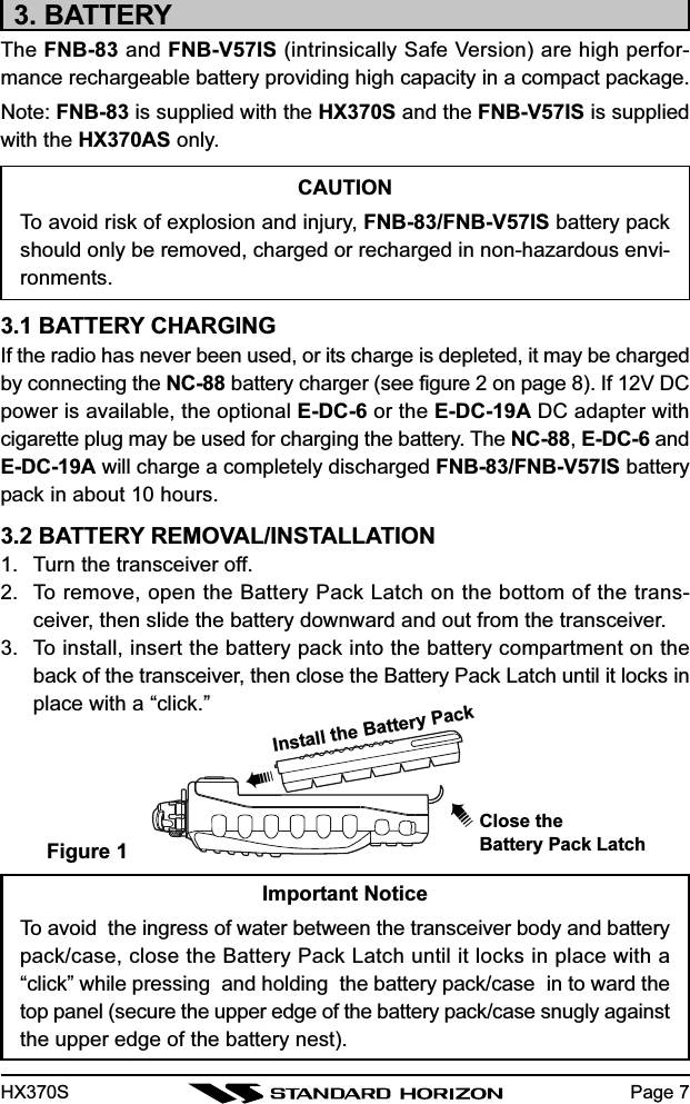
![HX370SPage 245.14 PRESET CHANNELS (1 ~ 8): INSTANT ACCESSEight user-assigned channels can be programmed for instant access.5.14.1 Programming1. Hold down the PRESET key, and press the [] or [] key (repeatedly, ifnecessary) until the desired channel number (from among the regularoperating channels) is displayed.2. With the desired channel number displayed, release the PRESET key.The “1” notation will appear on the LCD display for 1 second, indicatingthat the displayed channel is now saved in the Pre-set Channel “1” position. Then the preset channelnumber will disappear and the display comes backto the normal channel display.Repeat steps 1 and 2 to program the desired channels into Preset Channels1 ~ 8.To delete a Preset Channel, hold down the PRESET key and press the []or [] key until the Preset Channel number to be deleted is displayed, thenrelease the PRESET key.5.14.2 OperationPressing the PRESET key toggles between Preset Channel 1, 2, 3, 4, 5, 6,7, 8 and the last selected “regular” channel. Preset Channel 1 is repre-sented by “1” to the right of the channel number on the LCD for 1 second,and channel 2 is represented by “2,” and so forth. Then the preset channelnumberr will disappear and the display comes back to the normal channeldisplay.](https://usermanual.wiki/Yaesu-Musen/30083220.Revised-User-Manual/User-Guide-429198-Page-26.png)
![HX370SPage 265.17 VOICE SCRAMBLER UNITThe optional FVP-31 Voice Scrambler Unit permits secure voice communica-tions with stations within your network, which prevents others from listeningusing normal communication equipment.To activate the Voice Scrambler:1. Turn the radio off.2. Hold down the SQL key, then turn on the transceiver while still holdingdown the SQL key to enter the Setup Mode.3. Press the SQL key momentarily to select the Menu item (SCr).4. Press the [] or [] key momentarily select the scramble code (SC1,SC2, SC3, or SC4).5. When you have completed your selection, press the SQL key to savethe new setting, and then press the PTT switch to exit to normal operation.6. To disable the Voice Scrambler, select “oFF” in step 4 above.Installation of the FVP-311. Make sure that the transceiver is off. Remove the hard or soft case, ifused. Remove the battery pack.2. Locate the connector for the FVP-31 under the seal in the batterycompartment on the back of the transceiver, just peel off the seal.3. Align the connector on the FVP-31 with the transceiver’s connectorand gently press the unit into place.4. Place the Sponge Sheet (supplied with the HX370S) on the FVP-31.5. Affix the new (supplied with the FVP-31) seal, and replace the bat-tery. Installation is now complete.Figure 5Peel off the Seal Locate Connector Affix the new Seal➠➠➠Sponge Sheet](https://usermanual.wiki/Yaesu-Musen/30083220.Revised-User-Manual/User-Guide-429198-Page-28.png)
![HX370S Page 275.18 SETUP MODEThe HX370S’s Setup Mode allows a number of the HX370S operating pa-rameters to be custom-configured for your operating requirements.The Setup Mode is easy to activate and set, using the following procedure:1. Turn the radio off.2. Hold down the SQL key, then turn on the transceiver while still holdingdown the SQL key.3. “SEt” will appear on the display, indicating that the Setup Mode has beenactivated.4. Press the SQL key to select the Menu item to be adjusted (see below).5. Press the [] or [] key select the status or value of the Menu item.6. After completing your adjustment, press the SQL key to save the newsetting, and then press the PTT switch to exit to normal operation.Key BeepChannel FrequencyChannel NameDW DisplayLamp ModeScan LampScan DisplayVoice Scrambler➠➠➠➠➠➠➠➠➠➡“SQL” Key](https://usermanual.wiki/Yaesu-Musen/30083220.Revised-User-Manual/User-Guide-429198-Page-29.png)
![HX370SPage 285.18.1 bEP (KEY BEEP)Function: Enable/Disable the Keypad beeper.Available Values: ON/OFFDefault: ON5.18.2 CHF (CHANNEL FREQUENCY)Function: Enable/Disables the Channel Frequency display.Available Values: ON/OFFDefault: OFF5.18.3 CHn (CHANNEL NAME)Function: Changes the channel name shown on the display.1. Select the channel on which you wish to change the name before recall-ing this Menu item.2. Turn the radio off.3. Hold down the SQL key, then turn on the transceiver while still holdingdown the SQL key.4. “SEt” will appear on the display, indicating that the Setup Mode has beenactivated.5. Press the SQL key to select this Menu item “CHn.”6. Press the [] or [] key to select the first character(letter, number, or symbol) in the name you wish tochange, then press the MEM key to move to the nextcharacter.7. Repeat step 6 as many times as necessary to complete the name tag(up to 12 characters).8. After completing your adjustment, press the SQL key then PTT switch tosave the new setting and exit to normal operation.5.18.4 dUL (DW DISPLAY)Function: Selects the Dual Watch scanning display mode.Available Values: Normal/SpecialDefault: SpecialWhen “Special” is selected, channel number which is the LCD shows re-ceived channel.](https://usermanual.wiki/Yaesu-Musen/30083220.Revised-User-Manual/User-Guide-429198-Page-30.png)
![HX370S5.18.5 LP (LAMP MODE)Function: Select the LCD/Keypad Lamp mode.Available Values: KEY/Cnt (Continue)/OFFDefault: KEYKEY: Illuminates the LCD/Keypad for 5 seconds when any key ispressed.Cnt (Continue): Illuminates the LCD/Keypad continuously.oFF: Disables the LCD/Keypad illumination.5.18.6 SnL (SCAN LAMP)Function: Enable/Disable the Scan lamp while scanning is paused.Available Values: ON/OFFDefault: ON5.18.7 SCn (SCAN DISPLAY)Function: Select the display mode while scanning.Available Values: nor (Normal)/SPL (Special)Default: nor (Normal)nor (Normal): The channel number changes when scanning.SPL (Special): The channel number only changes when the radio receivesa transmission. This lets you see the last channel on whichsomeone called.Page 29Key Continue Off5.18.8 SCr (VOICE SCRAMBLER) [Requires optional FVP-31]Function: Enable/Disable the Voice Scrambler.Available Values: OFF/SC0/SC1/SC2/SC3Default: OFFNormal SpecialOff Code “SC1” Code “SC2” Code “SC3”](https://usermanual.wiki/Yaesu-Musen/30083220.Revised-User-Manual/User-Guide-429198-Page-31.png)

![HX370S Page 4310. SPECIFICATIONS7.1 GeneralFrequency range: 156 MHz - 163.275 MHz (Marine Band + WX Band)Channel Steps: 25 kHz137 MHz - 174 MHz (LMR)Channel Steps: 12.5 / 25 kHzFrequency stability: ± 2.5 ppm (–22 °F to +140 °F [–30 °C to +60 °C])Emission type: 16K0G3E, 16K0F3E, 11K0F3EAntenna impedance: 50 OhmsSupply voltage: 7.2 VDCCurrent consumption: 200 mA (Receive)40 mA (Standby, Saver Off)TX: 1.4 A (H)/0.9 A (M)/0.5 A (L)Operating Temperature: –22 °F to +140 °F (–30 °C to +60 °C)Waterproof rating: 30 minutes @ 1 meter depth (JIS 7)Case Size (W x H x D): 2.3” x 4.7” x 1.2” (58 x 120 x 30.5 mm)Weight (Approx): 13.4 oz (380 g) with FNB-837.2 TransmitterRF output power: 5 W/2.5 W/1 W @7.2 VModulation Type: Variable ReactanceMax deviation: ±5 kHz (Wide)±12.5 kHz (Narrow)Spurious emissions: At least 73 dB downMicrophone impedance: 2 k-Ohm7.3 ReceiverCircuit type: Double-conversion superheterodyneIntermediate Frequencies: 1st: 21.7 MHz2nd: 450 kHzSensitivity: 0.25 µV 12 dB SINADAdjacent channel selectivity: 70 dBIntermodulation response: 70 dBSelectivity: 12 kHz / 25 kHz (–6 dB/–60 dB) (Wide)6 kHz / 18 kHz (–6 dB/–60 dB) (Narrow)AF output: 600 mW @ 16 Ohm for 10 % THD (@7.2V)](https://usermanual.wiki/Yaesu-Musen/30083220.Revised-User-Manual/User-Guide-429198-Page-45.png)