Yaesu Musen 30163X3S MOBILE MARINE RADIO User Manual CPV350 Owner s Manual Chart Section V3 p65
Yaesu Musen Co., Ltd. MOBILE MARINE RADIO CPV350 Owner s Manual Chart Section V3 p65
Contents
- 1. USERS MANUAL 1 OF 2
- 2. USERS MANUAL 2 OF 2
USERS MANUAL 1 OF 2
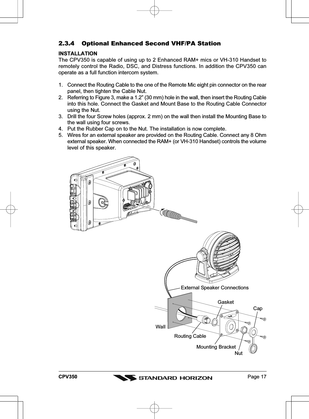
![Page 18 CPV350Remote Mic or External Speaker SelectionBy default the RAM+ or VH-310 Handset internal speaker is turned on, however using theRAM+ mic (or VH-310 Handset) this speaker can be turned off so the external speaker canbe used.RAM+ mic procedure1. Press and hold the [CALL/SET] key.2. Press the [] or [] key to select RADIO SETUP.3. Press the [CALL/SET] key.4. Press the [] key to until EXT SPK is shown and press the [CALL/SET]key.5. Press the [] or [] key to select oF (External speaker off) or on(External speaker on).6. Press the [CALL/SET] key to save the selection.7. Press the [16/9] key to exit this mode.VH-310 Procedure1. Press and hold the [CALL(MENU)] key.2. Press the [] or [] key to select RADIO SETUP.3. Press the [ENT] key4. Press the [] key to until EXT SPK is shown and press the [ENT] key.5. Press the [] or [] key to select oF (External speaker off) or on(External speaker on).6. Press the [ENT] key to save the selection.7. Press the [16/9] key to exit this mode.](https://usermanual.wiki/Yaesu-Musen/30163X3S.USERS-MANUAL-1-OF-2/User-Guide-645730-Page-18.png)
![Page 19CPV3502.3.5 NMEA ConnectionsNOTEThe CPV350 can send many sentences to external NMEA devices. The NMEA output wires areBrown and White and the NMEA Common is Green. If you have connected devices as shown inthe below table and need to feed NMEA to other devices (Autopilot, Radar ....) you can parallel wiresfrom the Brown or White wires.Pin Wire Color Description Connection Example Additional Information 1 Black -- - No Connection 2 Red -- - No Connection 3 Green NMEA Common Common for NMEA devices 4 Blue NMEA Input Port 1 Conncect to output of NMEA device Default is NMEA0183 5 Brown NMEA Output Port 1 Conncect to intput of NMEA device Default is NMEA0183 with GLL. RMB, RMC, and XTE sentences 6 Gray NMEA Input Port 2 Conncect to output of NMEA device Default is NMEA0183 7 White NMEA Output Port 2 Conncect to intput of NMEA device Default is NMEA0183 with GLL. RMB, RMC, and XTE sentences 8 Yellow NMEA Output Port 4 Connect autopilot Default is NMEA0183 with APA. APB, XTE, COG, and BOD sentences: When the FF520 is connected, port 2 input must be changed to “FF520.” To do this, press [MENU] two times, move the ShuttlePoint konb to highlightADVANCED SETUP, IN/OUT CONNECTIONS, PORT2 INPUT, FF520. Figure 2.3.5 IN/OUT CONNECTION menu2.3.6 Outputting NMEA to a Personal ComputerThe CPV350 can be connected to output Marks, Routes, and tracks to many PC programsavailable in the aftermarket. To send or receive User Points the PC Program must be ableto receive NMEA WPL and RTE sentences.2.3.7 Serial PC ConnectionOutputting Waypoints and RoutesThe CPV350 can be connected to output Marks, Routes and tracks to many PC programsavailable in the aftermarket. To send or receive User Points the PC Program must be ableto receive NMEA WPL and RTE sentences.PC DB9 Connection CPV350 ConnectionPin 2 Brown wirePin 3 BluePin 4 Green](https://usermanual.wiki/Yaesu-Musen/30163X3S.USERS-MANUAL-1-OF-2/User-Guide-645730-Page-19.png)
![Page 20 CPV3502.3.8 Outputting GPS CoordinatesSome PC programs use NMEA sentences from a GPS to show position. The CPV350outputs GLL, RMB and RMC.PC DB9 Connection CPV350 ConnectionPin 2 Brown wirePin 4 Green2.3.9 NMEA Data PageThe NMEA Data Page is very useful to see if an External device (example: Depth Sounder)is transmitting NMEA sentences to the GPS chart plotter. This page can also be used to seeif the GPS chart plotter NMEA output is being loaded down by an external NMEA deviceExample:Autopilot connected but the CPV350 but is not receiving NMEA data.Usually the Autopilot will be connected to the yellow wire.To check to see if the GPS chart plotter is transmitting the Autopilot sentences:1. Press [MENU]. Move the ShuttlePoint knob to highlight NMEA DISPLAY and press[ENT].2. Move the ShuttlePoint knob to highlight DATA and press [ENT].3. The NMEA DATA page is shown.4. Connect the Blue Wire on the GPS chartplotter to the junction of the yellow wire and theautopilot. The display should look similar to the picture below.5. If no data is shown press the [ZOOM] and move the knob on right side up to changeport.](https://usermanual.wiki/Yaesu-Musen/30163X3S.USERS-MANUAL-1-OF-2/User-Guide-645730-Page-20.png)
![Page 21CPV3502.4 GPS ANTENNA2.4.0 Mounting the GPS WAAS Smart AntennaThe CPV350 is supplied with a 12 Channel GPS WAAS Smart antenna. This antenna isdesigned to be mounted on a base, installed on an extension or even flush mounted.Choose a location for the antenna that has a clear view of the sky and is not located within3 FT of Radar or other transmitting antenna. Ensure there are no major obstructions orfixtures in the immediate proximity to the antenna. The antenna relies on direct “line of sight”satellite reception. If you are unsure of the chosen location, temporarily mount the antennain the desired location to verify correct operation. If mounted close to Radar, and after theGPS chartplotter has a fix, turn on the Caps on RADAR to ensure the GPS chartplotter holdsthe fix (use the GPS Status Page).2.4.1 Mounting on a PoleThe thread used on the antenna is an industry standard (1 inch 14TPI) used on a wide rangeof mounting brackets. Due to the manufacturing process of these mounting brackets youmay see some slop when tightening down the antenna to the bracket. This is no concernhowever as the antenna must be tightened until the antenna stops rotating.NOTEThe antenna cable can be cut and spliced to ease installation. Care must be taken whenreconnecting the antenna cable to protect from water and corrosion.2.4.2 Flush MountingNOTEBefore drilling holes, it is recommended the antenna be positioned where the location is plannedto be drilled, cable connected to the CPV350 and the CPV350 turned on to ensure a GPS fix isreceived.1. Remove the threaded base from the antenna dome.2. To ease installation a flush mounting template for the antenna has been included.3. Apply the mounting template sticker to the area that was verified for GPS reception.4. Then, drill out the 0.63” (16 mm) and 0.16” (4 mm) holes, and remove the template.5. Insert the cable into the 0.63” (16 mm) hole and route to the CPV350.6. Apply a small amount or RTV to the under side of the antenna.7. Place the antenna and then screw it into place using the screws. In some cases thescrew may not be long enough, if this happens simply apply more RTV to the undersideof the antenna to glue it into place. GPS OVERALL SHAPECUTTING TEMPLATECUTTING TEMPLATE4 mm [0.155"]4 mm [0.155"]0016 mm [0.63"] or greater004 mm [0.155"]Figure 2.4.2 Installing the GPS WAAS Smart antenna](https://usermanual.wiki/Yaesu-Musen/30163X3S.USERS-MANUAL-1-OF-2/User-Guide-645730-Page-21.png)
![Page 23CPV350External SpeakerEXTERNALNMEA DEVICEPA Speak erGreenBlue NMEA OUTNMEA OUTNMEA IN( )( )( )GrayShieldShieldRedWhite2.7 OPTIONAL BLACK BOX FISH FINDERSTANDARD HORIZON offers an optional BLACK BOX FISH FINDER called FF520. Pleaserefer to the Owner’s Manual supplied with the Fish Finder for connections and operation.When the FF520 is connected, port 2 input must be changed to “FF520.” To do this, press[MENU] two times, move the ShuttlePoint konb to highlight ADVANCED SETUP, IN/OUTCONNECTIONS, PORT2 INPUT, FF520. Figure 2.7 IN/OUT CONNECTION menu2.8 OPTIONAL VHF EXTERNAL SPEAKERTHE CPV350 has connections for an external VHF speaker for louder audio. Use StandardHorizon MLS-300 or MLS-310 for best performance.](https://usermanual.wiki/Yaesu-Musen/30163X3S.USERS-MANUAL-1-OF-2/User-Guide-645730-Page-23.png)
![Page 26 CPV3504. MAP FUNCTIONS4.0 NEW MAX FUNCTIONS MENU1. Press [MENU] two times. Move the ShuttlePoint knob to highlight MAX FUNCTIONSand press [ENT] or move the ShuttlePoint knob to the right. The MAX Functions menuappears on the screen:Figure 4.0 - Map Functions MenuThe available Functions are described in the following.4.0.0 Zoom TypeAllows more expansions or compression of the chart scale while zooming in or out. ZoomMode has two options; STANDARD (default) or FLEXI-ZOOM. When in FLEXI-ZOOMmode, a short zoom push causes a change of chart, while a long zoom push causes a pop-up window to be displayed on a corner of the screen. The window shows the current Zoomfactor. By pressing [ZOOM] and moving the knob up/down the map is expanded orcompressed according to the zoom factor selected. The window is automatically closed if[ZOOM] is not pressed for 2 seconds and the selected zoom factor will be used at the nextzoom in/out.To activate this function follow the procedure:1. Press [MENU] for two times. Move the ShuttlePoint knob to highlight MAX FUNCTIONSand press [ENT] or move the ShuttlePoint knob to the right.2. Move the ShuttlePoint knob to highlight ZOOM TYPE and press [ENT] or move theShuttlePoint knob to the right.3. The menu now shows two selections, STANDARD or FLEXI-ZOOM.4. Move the ShuttlePoint knob to select the selection and press [ENT].5. Press [CLR] until the menu disappears or an easier method is to move the ShuttlePointknob to the left a few times.4.0.1 Fonts & SymbolsOn MAX charts it is possible to set the size of all names and symbols drawn on the charts,selecting between Normal size (the regular characters size) and Large size.To activate this function follow the procedure:1. Press [MENU] two times. Move the ShuttlePoint knob to highlight MAX FUNCTIONSand press [ENT] or move the ShuttlePoint knob to the right.2. Move the ShuttlePoint knob to highlight FONTS & SYMBOLS and press [ENT] or movethe ShuttlePoint knob to the right.](https://usermanual.wiki/Yaesu-Musen/30163X3S.USERS-MANUAL-1-OF-2/User-Guide-645730-Page-26.png)
![Page 27CPV3503. The menu now shows two selections, NORMAL or LARGE.4. Move the ShuttlePoint knob to select the selection and press [ENT].5. Press [CLR] until the menu disappears or an easier method is to move the ShuttlePointknob to the left a few times.NORMAL size LARGE sizeFigure 4.0.1 - Example of Normal size (on the left side) and Large side (on the right side) settings4.0.2 Perspective ViewChart data may be projected in perspective mode during navigation. This function allowssetting the panoramic View of the chart. As the upper side of the map is more compressedthan the lower side, a wider map area is visible. The perspective view allows showing morechart information immediately ahead and around the cursor.Figure 4.0.2 - Perspective ViewTo activate this function follow the procedure:1. Press [MENU] for two times. Move the ShuttlePoint knob to highlight MAX FUNCTIONS](https://usermanual.wiki/Yaesu-Musen/30163X3S.USERS-MANUAL-1-OF-2/User-Guide-645730-Page-27.png)
![Page 28 CPV350and press [ENT] or move the ShuttlePoint knob to the right.2. Move the ShuttlePoint knob to highlight PERSPECTIVE VIEW and press [ENT] or movethe ShuttlePoint knob to the right.3. The menu now shows two selections, ON or OFF.4. Move the ShuttlePoint knob to select the selection and press [ENT].5. Press [CLR] until the menu disappears or an easier method is to move the ShuttlePointknob to the left until the chart page is shown.4.0.3 Dynamic Nav-AidsThis function enables the blinking of lights of the Nav-Aids. The blink period and color ofeach Nav-Aid is read from the Nav-Aid attributes available on the data cartridge. When theship is inside the Nav-Aid nominal range, the light of the Nav-Aid will start blinking.When Dynamic Nav-Aids option is set to On, when the flashing light is Off, or when fixposition is out of the sector, the light color is displayed by using a faint light color.To activate this function follow the procedure:1. Press [MENU] two times. Move the ShuttlePoint knob to highlight MAX FUNCTIONSand press [ENT] or move the ShuttlePoint knob to the right.2. Move the ShuttlePoint knob to highlight DYNAMIC NAV-AIDS and press [ENT] or movethe ShuttlePoint knob to the right.3. The menu now shows two selections, ON or OFF.4. Move the ShuttlePoint knob to select the selection and press [ENT].5. Press [CLR] until the menu disappears or an easier method is to move the ShuttlePointknob to the left until the chart page is shown.4.0.4 Safety Status Bar (DSI - Data Safety Indicator)When Safety Status Bar is On, a status bar with six boxes showing the status of certainfunctions is displayed. Any warning or alarm condition is identified by the red color toindicate possible risk.To activate this function follow the procedure:1. Press [MENU] two times. Move the ShuttlePoint knob to highlight MAX FUNCTIONSand press [ENT] or move the ShuttlePoint knob to the right.2. Move the ShuttlePoint knob to highlight SAFETY STATUS BAR and press [ENT] ormove the ShuttlePoint knob to the right.3. The menu now shows the following selections: ON (Safety Status Bar is shown), OFF(Safety Status Bar is not shown), ICON (Safety Status Bar is not shown, but a Warningalarm Icon is shown on the corner of the map screen as soon as any item controlled bythe DSI function returns an alarm condition. The Warning Icon remains displayed untilthe alarm condition persists. Placing the cursor over this Icon, a quick help message isshown next to the Icon, allowing to show the Safety Status Bar. In this case - when theSafety Status Bar is opened via Warning alarm Icon - it is allowed to obtain informationabout each “active” Safety Status box (the red ones): it is possible to select them byShuttlePoint knob movement left/right, and a list of active alarms is shown underneaththe selected box. By pressing [CLR], the Safety Status Bar is removed from the screen)4. Move the ShuttlePoint knob to select the selection and press [ENT].5. Press [CLR] until the menu disappears or an easier method is to press the ShuttlePointknob to the left a few times.](https://usermanual.wiki/Yaesu-Musen/30163X3S.USERS-MANUAL-1-OF-2/User-Guide-645730-Page-28.png)
![Page 29CPV350Figure 4.0.4 - Safety Status BarThe boxes are defined as follows:Zoom♦Normal: when the chart is displayed at normal scale.♦U. Zoom: red when the chart is under-zoomed out more than twice normalscale, gray otherwise.♦O. Zoom: red when the chart is over-zoomed in more than twice normal scale,gray otherwise.♦Chart Lock: red when the chart is zoomed in more than twice normal scale,gray otherwise.NOTEU. Zoom, O. Zoom and chart lock are used with Flexi-zoom selected.Best ScaleRed when a more detailed chart is available under the cursor position. Data OffRed when at least one of the following objects or layers is turned off (by the user):Depths/soundings; Wrecks/obstructions; Tracks/routes; Attention Areas; Nav-Aids. DeclutterDisplays red when clearing overlapping objects.DangersRed when “Guardian Technology” detects one of the following objects: Land, Inter-tidal, Depth Area, Rocks, Obstructions, Shoreline Constructions, Fishing Facility,Wrecks, Dragged area, Diffusion area, Mooring facilities, Pingos and Production in-stallations. CautionRed when “Guardian Technology” detects cautionary or restricted area.4.0.5 Currents PredictionWhen enabled shows the variation of the tidal arrows on the selected area at any given time.To activate this function follow the procedure:1. Press [MENU] two times. Move the ShuttlePoint knob to highlight MAX FUNCTIONSand press [ENT] or move the ShuttlePoint knob to the right.2. Move the ShuttlePoint knob to highlight CURRENTS PREDICTION and press [ENT]or move the ShuttlePoint knob to the right.3. A window is shown on the low-left side of the chart. Press [SET TIME] to set the date andtime manually, and [INCR. TIME]/[DECR. TIME] to decrease/increase time; press [EXIT] toexit.](https://usermanual.wiki/Yaesu-Musen/30163X3S.USERS-MANUAL-1-OF-2/User-Guide-645730-Page-29.png)
![Page 31CPV3505.0.0 How to show the pictures or diagrams of a Multimedia ObjectThey are shown on the chart page with the camera icon Move the cursor over the camera icon. You will get the quick info on the object and therewill be the camera icon on the top bar of the window:Figure 5.0.0a - Example of Quick Info on MULTIMEDIA objectPress [IMAGE] for 1 second to display the image on the screen or press [EXPAND] to openthe Full info on the object:Figure 5.0.0b - Example of Full Info on MULTIMEDIA objectOn the Full Info, there will be the small camera icon on a corner of the square containingthe object icon.To see the picture press [MENU] when the object with a picture is highlighted.When the picture is shown, it is possible to fit it to screen by pressing [ENT].When the picture is shown, it is possible to change the contrast by pressing [ZOOM] andmoving the knob.When the picture is shown, it is possible to display the next picture associated, if any, bypressing the ShuttlePoint knob left or right.5.1 ENHANCED PORT INFOMAX charts include additional port services that were not present before. Additionalattributes of Port Areas and Port Marinas have been included (Location, Country, Region,State, Harbor master telephone number etc.).](https://usermanual.wiki/Yaesu-Musen/30163X3S.USERS-MANUAL-1-OF-2/User-Guide-645730-Page-31.png)
![Page 32 CPV3506. CONTROLS AND INDICATORSLEGEND[MENU] If you see brackets around a bold and capital letter word this refers to a key press.[CHART] If you see brackets around a bold and small capital letter word this refers to a Soft Keypress. When a word(s) is bold capital letters and underlined, this refers to a menu selection item.6.0 CONTROLS AND CONNECTIONSThe GPS Chart plotter, VHF radio, PA and optional FF520 fish finder are controlled using thekeys located on the front panel. These labeled keys are dedicated to specific functions. As youpress a key, a single audio beep confirms the key action; every time a key press is not valid,three rapid beeps sound to indicate that the key action is not valid. There is also a ShuttlePointknob to move the cursor across the screen.The ZOOM keyPressing this key enables or disables the chart plotter zoom function or VHF channelselection.Press the [ZOOM] key and a zoom icon will appear on the top left of the display as shownbelow. When this icon is shown the zoom function is enabled and the channel selector knobis used to change the zoom levels. When the icon is not shown turning the knob changesthe VHF channels.To zoom in rotate the channel selector knob Clockwise (up) or to zoom out rotate thechannel knob counter clockwise (down). When finished zooming press the [ZOOM] key.Rotating the channel knob.NOTEThe GPS chartplotter contains a Worldwide background that allows you to zoom into 2 NM. Formore detail, a C-MAP NT+/MAX C-CARD must be purchased and installed.The ShuttlePoint knobThe ShuttlePoint knob moves the cursor about on the display screen, quickly andaccurately. It also scrolls the desired option in the menu page(s). It allows to exit from Homemode to Cursor mode. when the setup menu is selected, moving the knob to the right selectsthe desired option, as [ENT], moving it to the left exits from menu, as [CLR]. For a detailedexplanation of Cursor VS Home mode refer to section 6.1.1.The ENT keyPress [ENT] to select the desired option or to confirm selection.The CLR keyPress [CLR] to set Home mode. Also press [CLR] to exit from menu or data windows or toleave a menu without making changes, to abort selected function or to step backward froma selection made in the menu.The MENU keyPressing [MENU] one time selects the Main Menu. While the Main Menu is shown, movethe ShuttlePoint knob up or down or left or right to highlight a selection. Press the [ENTER]to choose the selection.Pressing [MENU] two times selects the Setup Menu.](https://usermanual.wiki/Yaesu-Musen/30163X3S.USERS-MANUAL-1-OF-2/User-Guide-645730-Page-32.png)
![Page 33CPV350Press and hold the [MENU] key for about 3 seconds allows the fields in the data windowsto be customized on the Chart, Navigation, Highway, GPS Status or NMEA display pages.The GOTO keyThis key is very useful when you desire to start navigating (goto) to a destination point. Whenpressed shows a popup window that allows you to select to start navigating to the positionof the cursor, Mark or Route.The MARK/MOB keyPressing [MARK/MOB] and immediately releasing places Mark under the ship's positionwhen in Home Mode (in Cursor Mode under the cursor).Press and holding [MARK/MOB] for about 3 seconds automatically places a MOB on theChart page and all navigation is towards the position of the MOB Mark.The RTE keyWhen pressed places a Waypoint. Succeeding presses place more Waypoints to form aRoute.The PWR key and Lamp/ContrastPress and hold [PWR] to turn the GPS chartplotter On or Off. When the CPV350 is on, pressthe [PWR] key to shown the contrast and Lamp popup window. Move the ShuttlePoint knobleft/right to adjust the backlight and up/down to adjust contrast.The Soft KeysThe 6 keys in the bottom part of the front panel (hereinafter named Soft Keys) have differentfunctions associated depending on the page selected: their labels are shown on the screenimmediately above the keys (the user can customize the function associated).These keys allow quick selection to the many pages the GPS chartplotter has. These keys canbe customized to your preference, however from the factory the keys are preprogrammed withthe following pages. From left to right CHART, NAV, HIGHWAY, CELESTIAL, NMEADISPLAY, LIST. Press any of the keys and you will see popup windows above the keys. Togoto a specific page press the key with the desired popup window. The popup windows willautomatically disappear if a key is not pressed or can be removed by pressing [CLR].6.1 GETTING STARTEDThe Getting Started section will take you through the frequently used operations and assistyou to customize the look of the GPS chartplotter.Legend:[MENU] If you see brackets around a bold and capital letter word this refers to a key press.[CHART]If you see brackets around a bold and small capital letter word this refers to a Soft Key press.GENERAL SETUP When a word(s) is bold capital letters and underlined, this refers to a menu selection item.6.1.0 Power On, Off and ShuttlePoint knob operation1. Press and hold [PWR] until the display shows the start-up page. To turn off, press andhold [PWR] until the display turns off.2. When the power is first turned on two pages (the start-up page, see the following picture,and the Caution page) are briefly shown before the GPS Status page.](https://usermanual.wiki/Yaesu-Musen/30163X3S.USERS-MANUAL-1-OF-2/User-Guide-645730-Page-33.png)
![Page 34 CPV350Figure 6.1.0 - Start-Up page3. When the GPS chartplotter is first turned on it will take some time for the GPS to acquirea fix of your position. Look closely at the GPS Status page and you will see satellites andrelative signal strengths. After a fixed is received the GPS chartplotter will automaticallyswitch to the Chart page with a ships icon centered on the screen.Cursor Ships Icon2121Figure 6.1.0a - GPS Status and Chart pages4. On the Chart page the ShuttlePoint knob is used to pan around the chart. Move the ShuttlePointknob to the left and you will notice a cross hair appears, this is called the cursor.5. When you move the ShuttlePoint knob you will notice DST and BRG values in the Datawindow change. This shows the Distance and Bearing from the GPS Fix of your vesselto the position of the Cursor.6. If the cursor is moved to the edge of the screen the GPS chartplotter will automaticallypan in the desired direction.6.1.1 Cursor Vs. Home ModeCursor ModeWhen the cursor is shown on the Chart page, this is called Cursor mode.In Cursor mode the position of the vessel will not stay in the center of the page and will moveright off the edge of the screen (as your boat moves) Cursor mode allows you to pan aroundand look at areas on the map. In this mode your can also measure distance and bearingsfrom your current position.NOTETo change from Cursor mode to Home mode press [CLR].Home modeWhen the ships icon is only shown on the Chart page (cursor is not shown) you are in](https://usermanual.wiki/Yaesu-Musen/30163X3S.USERS-MANUAL-1-OF-2/User-Guide-645730-Page-34.png)
![Page 35CPV350Home mode. Now as the ship moves through the water the vessels position will be kept inthe center of the display.6.1.2 Cursor and Menu selection speedThe GPS chartplotter allows you to control the speed the Cursor moves when theShuttlePoint knob is pressed. To change the speed:Figure 6.1.2 - Cursor Speed menu1. Press [MENU] two times. Move the ShuttlePoint knob to highlight GENERAL SETUPand press [ENT] or move the ShuttlePoint knob to the right.2. Move the ShuttlePoint knob to highlight CURSOR SPEED and press [ENT] or move theShuttlePoint knob to the right.3. The menu now shows two selections, CHART and MENU which allows the CursorSpeed to be selected to High, Medium or Low on Chart page or within the menus.4. With CHART or MENU selected, press [ENT] or move the ShuttlePoint knob to the right.Move the ShuttlePoint knob to the desired setting and press [ENT] or move theShuttlePoint knob to the right.5. Press [CLR] until the menu disappears or an easier method is to press the ShuttlePointknob to the left a few times.6. Move the cursor on the Chart page and see if the speed is to your liking.6.1.3 Changing the Ships IconThe cursor may be changed to any of the following:Figure 6.1.3 - Ship icons1. Press [MENU] two times. Move the ShuttlePoint knob to highlight GENERAL SETUPand press [ENT] or move the ShuttlePoint knob to the right.2. Move the ShuttlePoint knob to highlight SHIP ICON and press [ENT] or move theShuttlePoint knob to the right to show the popup window with ship icons.3. Move the ShuttlePoint knob to select the desired icon and press [ENT] or move theShuttlePoint knob to the right to select a new icon.4. Press [CLR] or move the ShuttlePoint knob to the left to exit the menu and show theChart page.](https://usermanual.wiki/Yaesu-Musen/30163X3S.USERS-MANUAL-1-OF-2/User-Guide-645730-Page-35.png)
![Page 36 CPV3506.1.4 Changing the backlight and contrastWith the GPS chartplotter turned On, briefly press [PWR] to show the light and contrastpopup window. Move the ShuttlePoint knob to the left or right to adjust the LCD backlightintensity or up or down to change the LCD contrast. Press [ENT] to set.Figure 6.1.4 - Backlight and Contrast adjustment6.1.5 Selecting North Up or Course UpYou may select the Chart page between NORTH UP and COURSE UP which the top of theChart page oriented so it will always show the area ahead of the direction your vessel istraveling.Figure 6.1.5 - Course Up/North Up menu1. Press [MENU] two times. Move the ShuttlePoint knob to highlight GENERAL SETUPand press [ENT] or move the ShuttlePoint knob to the right.2. Move the ShuttlePoint knob to highlight COURSE UP/NORTH UP and press [ENT] ormove the ShuttlePoint knob to the right.3. Another popup window will be shown with NORTH UP and COURSE UP, move theShuttlePoint knob to the desired selection and press [ENT] or move the ShuttlePointknob to the right.4. Press [CLR] or move the ShuttlePoint knob to the left to exit the menu and show theChart page.NOTEWhen the GPS chartplotter is in COURSE UP mode a small arrow icon will be shown on the Chartpage indicating the direction of North.](https://usermanual.wiki/Yaesu-Musen/30163X3S.USERS-MANUAL-1-OF-2/User-Guide-645730-Page-36.png)
![Page 37CPV3506.2 ADJUSTING THE TIMEThe time information supplied by the GPS satellites is in Universal Time Coordinates (UTCor Greenwich England Mean Time). To change the GPS chartplotter to read the correcttime, first you must figure out the offset and if it is daylight savings time. For example on theWest coast of the United States or Pacific Standard Time the offset needed would be –08:00or –07:00 for daylight savings time, Eastern Standard Time –05:00 or –04:00 for daylightsavings time.Figure 6.2 - Adjusting TimeNOTEThis map shows offset for standard time. For daylight saving time, subtract one hour from the offset time.Figure 6.2a - Time Setup menu1. Press [MENU] two times. Move the ShuttlePoint knob to highlight GENERAL SETUPand press [ENT] or move the ShuttlePoint knob to the right.2. Move the ShuttlePoint knob to highlight TIME SETUP and press [ENT] or move theShuttlePoint knob to the right.3. Move the ShuttlePoint knob to highlight GPS TIME OFFSET and press [ENT] or movethe ShuttlePoint knob to the right.4. Move the ShuttlePoint knob down to select +00:00, press [ENT] and move theShuttlePoint knob to the right to edit the number.5. Look at the table and find the offset for your area. You will need to enter this offset tomake the GPS chartplotter shows the correct time.](https://usermanual.wiki/Yaesu-Musen/30163X3S.USERS-MANUAL-1-OF-2/User-Guide-645730-Page-37.png)
![Page 38 CPV3506. Move the ShuttlePoint knob to the “+”. Move the ShuttlePoint knob up or down to changeto the desired offset.7. Next move the ShuttlePoint knob to the right to select Hours and move the ShuttlePointknob up or down to change the hour.8. Repeat this method to change the minutes, if necessary.9. Once you have the correct GPS time offset, press [ENT] to set.6.3 SELECTING LORAN TD OR OTHER COORDINATE SYSTEMThe GPS Fix coordinates can be changed to show Latitude/Longitude, Loran TD’s or UTM.Below is the window that will appear when customizing the Coordinate System.Figure 6.3 - Coordinate System menu1. Press [MENU] two times. Move the ShuttlePoint knob to highlight ADVANCED SETUPand press [ENT] or move the ShuttlePoint knob to the right.2. Move the ShuttlePoint knob to highlight NAVIGATE and press [ENT] or move theShuttlePoint knob to the right.3. Move the ShuttlePoint knob to highlight COORDINATE SYSTEM and press [ENT] ormove the ShuttlePoint knob to the right.4. Move the ShuttlePoint knob to highlight the desired coordinate type and press [ENT] ormove the ShuttlePoint knob to the right.5. Press [CLR] or move the ShuttlePoint knob to the left until the Chart page is shown.NOTEIf the TD is selected, you should set the Chain, Pair, ASF1, ASF2 and Alter. If the TD numbers arenot correct the Pair letters may be backwards. Reversing the two letters usually solves this issue.Example Y/Z change to Z/Y.](https://usermanual.wiki/Yaesu-Musen/30163X3S.USERS-MANUAL-1-OF-2/User-Guide-645730-Page-38.png)
![Page 39CPV3506.4 CHANGING THE CHART COLORThe GPS chartplotter has preprogrammed settings allowing you to customize the look of theChart page. The default is “Sunlight” however there are other settings: Normal, Classic,NOAA and Night. Night is very useful during evening hours so not to impair night vision.Figure 6.4 - Display Color menu1. Press [MENU] two times. Move the ShuttlePoint knob to highlight GENERAL SETUPand press [ENT] or move the ShuttlePoint knob to the right.2. Move the ShuttlePoint knob to highlight DISPLAY COLOR and press [ENT] or move theShuttlePoint knob to the right.3. A popup window will be shown with Normal, Classic, NOAA, Night and Sunlight. Movethe ShuttlePoint knob to the desired selection and press [ENT] or move the ShuttlePointknob to the right.4. Press [CLR] or move the ShuttlePoint knob to the left to exit the menu and show theChart page.6.5 SELECTING PAGES USING SOFT KEYSThe Soft Keys located under the LCD are used to select the pages quickly without the needto go into the menu. The default pages are CHART, NAV, HIGHWAY, CELESTIAL, NMEADISPLAY and LIST.When one of the Soft Keys is pressed popup windows above each Soft Key are shown withthe key description. Press the Soft Key with the desired page description and the GPSchartplotter will change to that page.KtsM3.1015° 353°MCHARTGPS STATUSCELESTIALNMEA DISPLAYNAVIGATION HIGHWAYFISH FINDER full screen windowShown only with optional F 520 connectedFFigure 6.5 - Screen display pages](https://usermanual.wiki/Yaesu-Musen/30163X3S.USERS-MANUAL-1-OF-2/User-Guide-645730-Page-39.png)
![Page 40 CPV3506.6 CUSTOMIZING THE SOFT KEYSThe Soft Keys can be individually customized from the default pages (discussed above) tothe following: CHART, CHART/COMPASS, CHART/HIGHWAY, NAVIGATION, HIGH-WAY, CELESTIAL, GPS STATUS, DSC LOG*, DSC DIRECTORY*, NMEA DISPLAY,NMEA DATA, DEPTH TREND, WIND SPEED TREND, TEMP TREND, SOG TREND,MARKS/WAYPOINTS and USER C-CARD.When the Optional FF520 50/200kHz BLACK BOX FISH FINDER is connected, any SoftKey can be customized to show 50 or 200kHz full page, 50 or 200kHz Chart/Fish split screenand zoom screens.Figure 6.6 - Window options of the selected Soft Key1. To change, momentarily press any of the Soft Keys, then press and hold the Soft Keyyou want to customize.2. A popup window will be shown with the above settings.3. Move the ShuttlePoint knob up or down to select the desired page.4. Press [ENT] or move the ShuttlePoint knob to the right to save the page to the selectedSoft Key.6.7 OTHER SETTINGS IN GENERAL SETUP MENUYou will notice the GENERAL SETUP menu has other selections that allow you to customize:TIME SETUP Selects a submenu to allow the time setup. It is possible to set the GPS Time Offset,choosing the UTC or Local Time display, and the Time Format, switching 12 or 24 hourstime format.DATE FORMAT Allows choosing date format MM-DD-YY or DD-MM-YY.COURSE UP/NORTH UP Selections are:North Up : The Top of the page is fixed to NorthCourse Up : The top of the page is orientated to the direction the vessel is heading.KEYPAD BEEP Allows the beep produced when a key is pressed to be turned on or off.UNITS OF MEASURE Units of Measure can be selected for Distance, Speed, Depth, Altitude and Temperature.NAV AIDS PRESENTATION Allows the Nav Aids presentation to drawn using NOAA symbology when US is selectedor International symbols will be used when International is selected. When selected thesefunctions affects how the icons for Lights, Signals, Buoys and beacons are displayed.DISPLAY COLOR Changes the background colors of the chart page to enhance the visibility of the screendepending on the surrounding light conditions. Normal is recommended when the GPSchartplotter is not exposed to the direct sunlight. When this mode is set the maps aredisplayed in order to use colors as similar as possible to ones used in the original papercharts. Classic uses vivid chart colors presentation. NOAA allows setting NOAA paperchart colors presentation. Night is recommended when the environment is dark in orderto reduce the glare of the display. The GPS chartplotter displays maps and screen indarker colors. Sunlight (default) is designed to enhance the visibility of the screen whenthe GPS chartplotter is exposed to sunlight. The maps are much brighter than in the other](https://usermanual.wiki/Yaesu-Musen/30163X3S.USERS-MANUAL-1-OF-2/User-Guide-645730-Page-40.png)
![Page 41CPV350modes and the depth areas are filled with the white color so different depth areas noteasily distinguishable.SHIP ICON Allows selection of one of 5 choices of ship icons that represent you vessels positionshown on the chart page.CURSOR SPEED Selects the preferred speed among Low, Medium and High for the cursor in the Chart pageand within the menu.MEASURE DISTANCE When this function is turned on allows a distance to be measured between two pointsusing the ShuttlePoint knob and [ENTER] keyWINDOWS SETUP This menu selection allows the data windows to be customized on the Chart andNavigation pages.LANGUAGE Allows changing the language for menus and data screens.AUTO INFO By default when the cursor is moved over a buoy, Mark or other item a popup window willshow information of the item. This menu item allows the window to be turned on or off.CURSOR WINDOW By default when the cursor is moved a window is shown with the Lat/Lon Distance andbearing from the vessels location to the cursor. This selection allows the window to beturned off.CURSOR POSITION The position of the cursor (vessels location) can be customized so it centered in the middleor centered on the bottom of the chart page. The default is “Bottom”.COG TIME LINE Is a line projected from the vessel icon which indicates the distance your vessel will travelat the current speed. Selections are 2, 10, 30 minutes, 1, 2 hours and infinite.6.8 INFORMATION PAGEFrom Setup Menu page it is possible to select an Information page containing Software,Chart and Optional devices information.XXXXXX Version YY.YYM-NA-M632.00 LOS ANGELES and SAN PEDRO BAYSSoftware System Information12Cartography Information3Storage Capacity321Figure 6.8 - Information page1. Press [MENU] two times. Move the ShuttlePoint knob to highlight About... and press[ENT] or move the ShuttlePoint knob to the right.2. The Information page appears on the screen (see the previous Figure).3. Press [CLR] or move the ShuttlePoint knob to the left to exit and show the Chart page.](https://usermanual.wiki/Yaesu-Musen/30163X3S.USERS-MANUAL-1-OF-2/User-Guide-645730-Page-41.png)