Yaesu Musen 30163X3S MOBILE MARINE RADIO User Manual CPV350 Owner s Manual Chart Section V3 p65
Yaesu Musen Co., Ltd. MOBILE MARINE RADIO CPV350 Owner s Manual Chart Section V3 p65
Contents
- 1. USERS MANUAL 1 OF 2
- 2. USERS MANUAL 2 OF 2
USERS MANUAL 2 OF 2
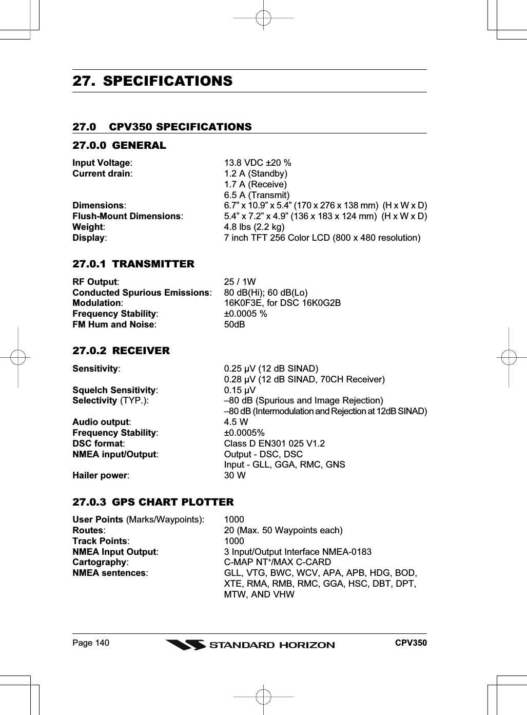
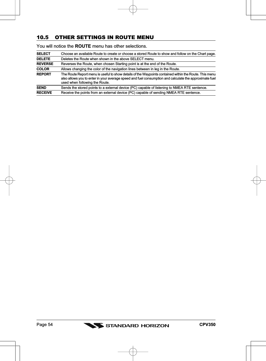
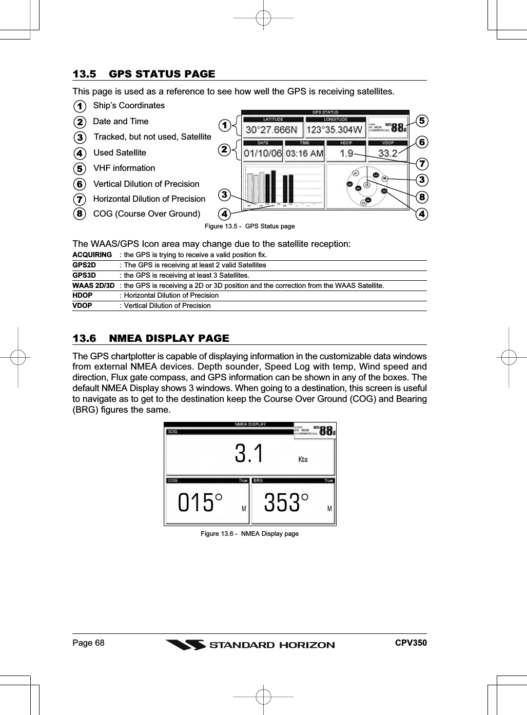
![Page 42 CPV3507. USING FIND SERVICES & MORE FUNCTIONWith a C-MAP NT+/MAX C-CARD installed the GPS chartplotter allows you to search fora Port Service, Port, Tide Stations, Wrecks, Obstructions, POIs, Lakes, User Points, orGPS Coordinates.7.0 PORT SERVICES1. Press [MENU]. Move the ShuttlePoint knob to highlight FIND SERVICES and press[ENT].2. Move the ShuttlePoint knob to highlight PORT SERVICE and press [ENT] or move theShuttlePoint knob to the right.3. A popup window will be shown with the Port Services.4. Move the ShuttlePoint knob to highlight the desired Service and press [ENT].5. Another popup window will show the name, distance and position of the Services closestto your location.6. Using the ShuttlePoint knob, highlight the desired Service and press [ENT] which willshow the name and phone number of the Service.7. Press [CLR] which will show the available Services at the location.8. Press [CLR] to show the actual position of the Services.Figure 7.0 - Port Services7.1 OTHER AVAILABLE SEARCHESPORT BY NAME Searches and shows on the Chart page the list of all ports stored on the C-CARD in alphabeticorderPORT BY DISTANCE Searches and shows the list of all ports stored on the C-CARD in distance orderTIDE STATIONS Searches for the closest Tide Station and shows the information of the tide stationWRECKS Searches and shows on the Chart page for the closest WrecksOBSTRUCTIONS Searches and shows on the Chart page for the closest ObstructionsUSER POINTS Searches and shows on the Chart page for the closest User Points (Marks or Waypoints)COORDINATES Searches and shows on the Chart page for GPS CoordinatesPOIs Searches and shows information on the selected Point Of InterestLAKES Searches and shows information on the selected LakeINFORMATION Searches and shows information on the selected point](https://usermanual.wiki/Yaesu-Musen/30163X3S.USERS-MANUAL-2-OF-2/User-Guide-645731-Page-1.png)
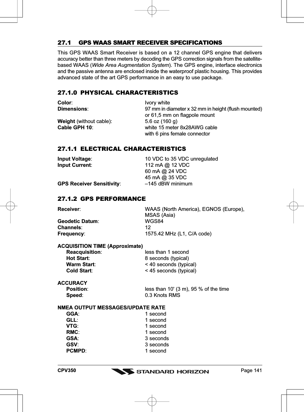
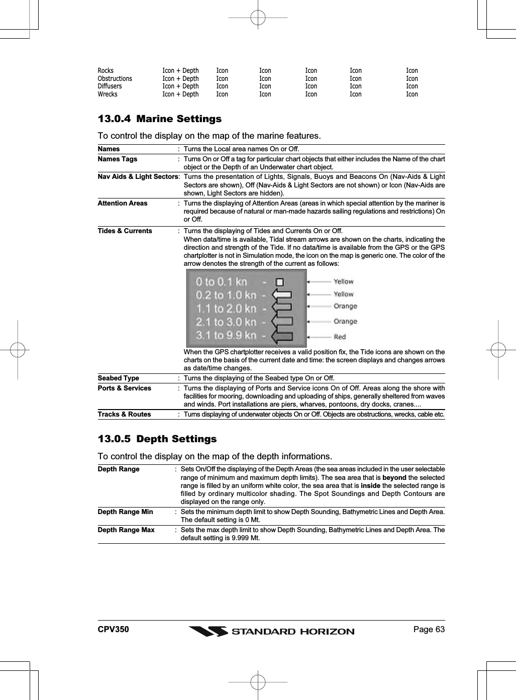
![Page 43CPV3507.2 INFO ON LAKES (WITH OPTIONAL C-MAP LAKES CARTOGRAPHY)7.2.0 Quick Info On LakesUpon viewing the chart of a lake, you will click on to query the available informationimmediately displayed with many details. For example, see the following picture:Lakes Info iconFigure 7.2.0 - Example of Lakes infoWhen the cursor is placed over the icon, the icons of the available services are shown:Figure 7.2.0a - Quick Info: available servicesIf you press [ENT] all available information about the cartographic point under the cursorwill be shown. See the next paragraph.7.2.1 Full Info On LakesThe following is an example of Full Info on Lakes:Figure 7.2.1 - Example of Full Info page](https://usermanual.wiki/Yaesu-Musen/30163X3S.USERS-MANUAL-2-OF-2/User-Guide-645731-Page-2.png)
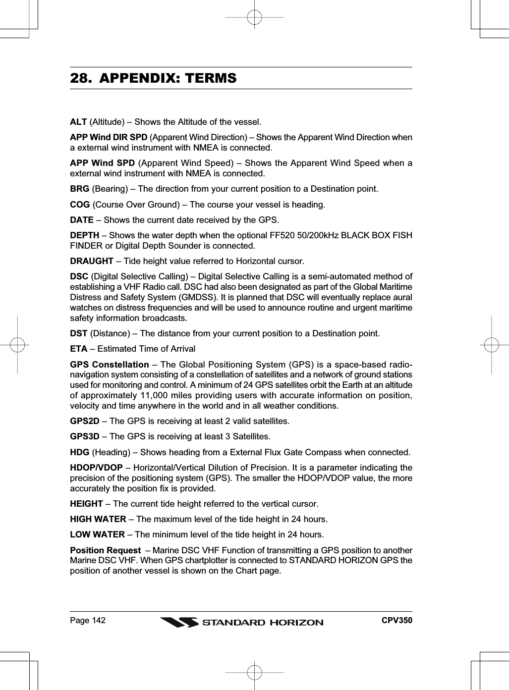
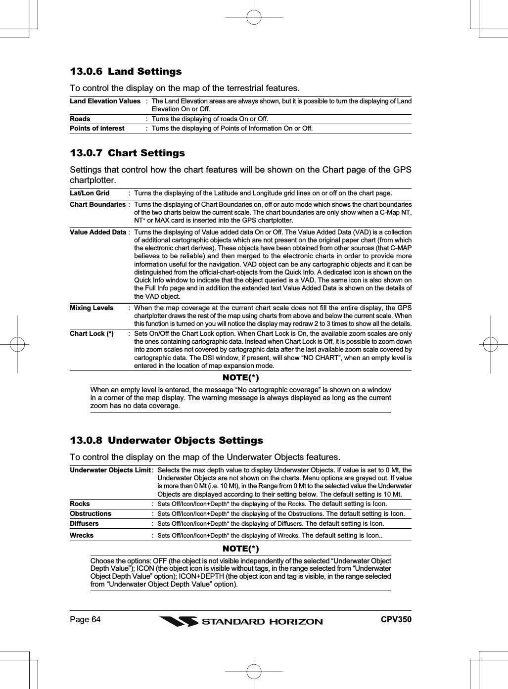
![Page 44 CPV350To see the “Fishing” object press [MENU] (when the “Fishing” object is highlighted). On thescreen appears:Figure 7.2.1a - Example of picture associated to the Fishing object](https://usermanual.wiki/Yaesu-Musen/30163X3S.USERS-MANUAL-2-OF-2/User-Guide-645731-Page-3.png)
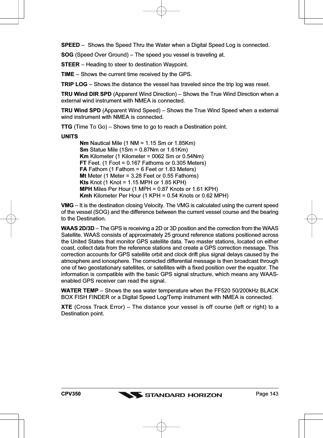
![Page 45CPV3508. CREATING MARKSMARKCan be a stand alone position or be linked to a Route. A Mark is placed on the Chart pageusing [MARK/MOB] or by entering in information in the Mark/Wpt List NEW MARKselection.WAYPOINTSAlways linked to a Route. Are placed on the Chart page using [RTE].NOTEThe difference between a Mark and a Waypoint isa. When a Route is created using WAYPOINTS and the ROUTE is deleted the WAYPOINTs arealso deleted.b. If a Route is created using MARKS and the ROUTE is deleted the MARKs remain.8.0 CREATING A NEW MARK USING THE CHART PAGE1. Move the ShuttlePoint knob to the desired or approx. Lat/Lon and press [MARK/MOB].2. You will notice a Mark is placed under the location of the Cursor and a popup windowis shown with the exact Lat/Lon of the Mark.3. If the position is incorrect press [EDIT] that will allow you to change the position, Markname, icon type and color of the icon.Vessel locationMark placed under CursorLat/Lon of Mark, DST/BRGfrom vessel location214Press Soft Key to show theMarks/Waypoint List, to edit,to move or to delete Mark31243Figure 8.0 - Mark creation8.1 EDITING A MARKIf a Mark has previously been created and you wish to Edit it, move Cursor over the top of the Mark.Figure 8.1 - Mark editing1. After a Mark is created, press [EDIT] to show the edit popup window.2. Use the ShuttlePoint knob to change to the desired Mark Icon, when finished press[ENT].3. Move the ShuttlePoint knob to the right to select the Mark Name. Press [ENT] an the](https://usermanual.wiki/Yaesu-Musen/30163X3S.USERS-MANUAL-2-OF-2/User-Guide-645731-Page-4.png)
![Page 46 CPV350first digit in the name will be highlighted.4. Move the ShuttlePoint knob up or down to select the first character.5. Move the ShuttlePoint knob to the right to select the next character.6. Repeat steps 4 and 5 until the Mark name is shown. Press [ENT].7. Move the ShuttlePoint knob to the right and press [ENT] to change the Mark Icon’sColor.8. Move the ShuttlePoint knob to up/down, left/right to select the Mark Icon’s Color. Whenfinished press [ENT].9. Move the ShuttlePoint knob to the right to select the Lat/Lon and press [ENT].10. Move the ShuttlePoint knob up or down to select the first character.11. Move the ShuttlePoint knob to the right to select the next character.12. Repeat steps 10 and 11 until the desired position is shown. Press [ENT] and [CLR] tostore the Mark.8.1.0 Deleting a Mark or WaypointMove the cursor over the Mark or Waypoint to delete. Press [DELETE]. A Warning popupwindow will be shown. Select YES and press [ENT].8.1.1 Moving a Mark or WaypointPlace the cursor over the Mark or Waypoint which you want to move. Press [MOVE]. Usethe ShuttlePoint knob to move the cursor. A dotted line, connecting the previous Waypointposition to the new position, is shown:Figure 8.1.1 - Moving Mark or Waypoint (I)Press [ENT] ([CLR] to abort the move), the Waypoint appears in the new position.Figure 8.1.1a - Moving Mark or Waypoint (II)](https://usermanual.wiki/Yaesu-Musen/30163X3S.USERS-MANUAL-2-OF-2/User-Guide-645731-Page-5.png)
![Page 47CPV3508.2 MARKS/WAYPOINTS LISTThe Marks/Wpt List shows all the Marks and Waypoints that have been stored into the GPSchartplotter. This page also allows you to:ICON Allows sorting by icon typeFIND Searches through the Marks or Waypoints to find a point by name using the ShuttlePoint knobLOCATE Shows the position of a Mark or Waypoint on the Chart pageEDIT Allows you to edit a previous stored Mark or WaypointSORT Sort the name of the Mark or Waypoint in ascending or descending orderNEW MARK Allows entering in Marks, editing icon type and positionMODE This selection controls how the Marks or Waypoints are shown on the Chart page. Selections are:a. SHOW - icon and name are shownb. ICON - only icon (no name) is shownc. HIDE - Mark or Waypoint is hiddend. SHOW ALL - All Marks or Waypoints are showne. ICON ALL - All Icons are shown without namef. HIDE ALL - All Marks or Waypoints are hiddenDELETE Delete the selected pointDEL ALL Delete all stored pointsSEND Sends the stored points to a external device (PC) capable of listening to NMEA WPL sentence.RECEIVE Receive the points from an external device (PC) that is capable of sending NMEA WPLsentence.NOTEThe SEND and RECEIVE functions are usually used by navigation programs running on a PersonalComputer example Nobeltech.Figure 8.2 - Marks/Waypoints List8.3 CREATING A NEW MARK WITH THE MARKS/WAYPOINTS LISTNOTEThis function is very useful if you have a list of Marks that you want to enter into the GPS chartplotter.1. Press [MENU]. Move the ShuttlePoint knob to highlight USER POINTS and press[ENT].2. Move the ShuttlePoint knob to highlight Marks/Wpt and press [ENT].3. The Marks/Wpt List page will be shown (see previous picture).4. To create a New Mark, move the ShuttlePoint knob to the right to highlight NEW MARKand press [ENT].5. Press [ENT] to change to show the Icon popup window.6. Move the ShuttlePoint knob to highlight the desired Icon and press [ENT].7. Move the ShuttlePoint knob to the right to select the Mark name. Press [ENT] and the](https://usermanual.wiki/Yaesu-Musen/30163X3S.USERS-MANUAL-2-OF-2/User-Guide-645731-Page-6.png)
![Page 48 CPV350first digit in the name will be highlighted.8. Move the ShuttlePoint knob up or down to select the first character.9. Move the ShuttlePoint knob to the right to select the next character.10. Repeat steps 8 and 9 until the Mark name is shown. Press [ENT].11. Move the ShuttlePoint knob to the right to select the Lat/Lon and press [ENT].12. Move the ShuttlePoint knob up or down to select the first character.13. Move the ShuttlePoint knob to the right to select the next character.14. Repeat steps 12 and 13 until the desired position is shown. Press [ENT] and [CLR], aWARNING “Save the new Mark?” popup window will be shown, move the ShuttlePointknob to the right or left to select YES or NO and press [ENT].8.4 GOTO CURSORThe GPS chartplotter allows you to quickly start navigating to the Cursor, Mark or Route.GOTO CURSOR1. Move the ShuttlePoint knob to the exact position you want to navigate to.2. Press [GOTO] and a GOTO popup window will be shownFigure 8.4 - GO TO menu3. Move the ShuttlePoint knob to highlight CURSOR and press [ENT].4. The GPS chartplotter is now navigating from your current position to the locationselected at step 1.Figure 8.4a - Navigating to Cursor Example5. Now the GPS chartplotter shows a navigation line between the vessels location and thedestination point. A popup window shows the Distance (DST) and Bearing (BRG) fromthe vessels location to the destination point.6. The GPS chartplotter is in Cursor mode, to switch to Home mode press [CLR] to so thevessel stay in the center of the page.7. Two Soft Keys are also shown that allow you to quickly switch to the HIGHWAY pageor to stop navigation.8. To STOP Navigation, press [GOTO] and the WARNING page is shown. Select STOPand press [ENT].](https://usermanual.wiki/Yaesu-Musen/30163X3S.USERS-MANUAL-2-OF-2/User-Guide-645731-Page-7.png)
![Page 49CPV3508.5 GOTO MARK1. Move the ShuttlePoint knob to an open position (no buoy, warning etc. under the cursor)on the Chart page.2. Press [GOTO] to show the GOTO popup window.3. Move the ShuttlePoint knob to highlight MARK and press [ENT] to show the Marks/WptList.4. Move the ShuttlePoint to the highlight the desired Mark or Waypoint and press [GOTO].5. You will notice a circle is drawn around the Icon Symbol. This means the GPSchartplotter is now navigating to the point.6. Press [CLR] to switch to the Chart page or Highway page to start navigating to the point.](https://usermanual.wiki/Yaesu-Musen/30163X3S.USERS-MANUAL-2-OF-2/User-Guide-645731-Page-8.png)
![Page 50 CPV3509. MAN OVER BOARD (MOB) FUNCTIONDuring navigation, the “MOB” feature provides a one-touch method of storing a location(such as a point were a crew member fell overboard). In this mode, the GPS chartplotterplaces a MOB point on the Chart page and all the navigation data shown is related tonavigating back to this point, allowing you to retrace your path to the MOB point efficiently.1. On the Chart page, press [MARK/MOB] to start navigating back to the point.2. You will notice a MOB Mark will be laid on the Chart page and all navigation is referringback to this point.3. If the cursor is moved over the MOB Icon, popup windows over Soft Keys will be shownallowing quick access to the Navigation or Highway pages.9.0 DELETING A MOB POINT1. Move the ShuttlePoint knob until the cursor is over the top of the MOB icon.2. Press [DELETE], a popup window will be shown to confirm deleting the MOB point.3. Move the ShuttlePoint knob to highlight YES and press [ENTER].](https://usermanual.wiki/Yaesu-Musen/30163X3S.USERS-MANUAL-2-OF-2/User-Guide-645731-Page-9.png)
![Page 51CPV35010. ROUTESThe GPS chartplotter has the capability to store 20 Routes with a maximum of 50 Waypointseach.A Route can consist of Waypoints or Marks. The difference is when a Route is made usingWaypoints and the Route is deleted the Waypoints are also deleted. However if a Route ismade of Marks and the Route is deleted the Marks stay in memory.10.0 CREATING A ROUTE USING WAYPOINTS 1. On the Chart page move the ShuttlePoint knob to the Lat/Lon of the starting Waypointin the Route. 2. Press [RTE], you will notice the Starting Waypoint will be placed under the cursor. 3. Move the ShuttlePoint knob to the second Lat/Lon of the next leg in the Route. 4. Press [RTE]. You will notice another Waypoint is shown under the cursor and a line joinsthe starting Waypoint to the Second Waypoint.Figure 10.0 - Creating a Route using Waypoints 5. Repeat steps 3 and 4 until all Waypoints are entered into the Route.NOTEAt this point the Route is saved as ROUTE01. If you would like to save the Route under a specificname follow the remaining steps.6. To name the Route press [MENU]. Move the ShuttlePoint knob to highlight USERPOINTS and press [ENT]. 7. Move the ShuttlePoint knob to highlight ROUTE and press [ENT].8. Move the ShuttlePoint knob to highlight REPORT and press [ENT] or move theShuttlePoint knob to the right.9. Move the ShuttlePoint knob to highlight NAME and press [ENT]. A popup window willbe shown.10. Move the ShuttlePoint knob up/down to change the characters and left/right to selecta different character in the Routes Name.](https://usermanual.wiki/Yaesu-Musen/30163X3S.USERS-MANUAL-2-OF-2/User-Guide-645731-Page-10.png)
![Page 52 CPV350Figure 10.0 - Route Report11. When finished press [ENT] to save.12. Press [CLR] to show the Chart page.10.1 MAKING ADDITIONAL ROUTESTo create another Route the GPS chartplotter must be told that you want to create a secondRoute.1. Press [MENU]. Move the ShuttlePoint knob to highlight USER POINTS and press[ENT].2. Move the ShuttlePoint knob to highlight ROUTE and press [ENT].3. Move the ShuttlePoint knob to highlight SELECT and press [ENT] or move theShuttlePoint knob to the right.4. Move the ShuttlePoint knob to an open Route number example Route 2.5. Press [ENT] or move the ShuttlePoint knob to the right.6. Press [CLR] or move the ShuttlePoint knob to the left until the Chart page is shown.7. To create the new Route, follow the steps in Creating a Route using Waypoints or Markssections.10.2 CREATING A ROUTE USING MARKS ON THE CHART PAGETo create a Route containing Marks you first must create the Marks and show them on theChart page.1. Move the ShuttlePoint knob over the top of a Mark that you wish to be the starting pointin the Route and press [RTE].2. Next move the ShuttlePoint knob until the cursor is over the Mark that you want to bethe next leg in the Route.3. Press [RTE]. You will notice a bearing line joins the first and second Mark which meansthese Marks are selected into the Route.4. Repeat steps 3 and 4 until all Marks are entered into the Route.NOTEAt this point the Route is saved as ROUTE01. If you would like to save the Route under a specificname follow the remaining steps.5. To name the Route press [MENU]. Move the ShuttlePoint knob to highlight USERPOINTS and press [ENT].6. Move the ShuttlePoint knob to highlight ROUTE and press [ENT].](https://usermanual.wiki/Yaesu-Musen/30163X3S.USERS-MANUAL-2-OF-2/User-Guide-645731-Page-11.png)
![Page 53CPV3507. Move the ShuttlePoint to highlight REPORT and press [ENT] or move the ShuttlePointknob to the right.8. Move the ShuttlePoint knob to highlight NAME and press [ENT] or move the Shuttle-Point knob to the right. A popup window will be shown.9. Move the ShuttlePoint knob up/down to change the characters and left/right to selecta different character in the Routes Name.10. When finished press [ENT] to save.11. Press [CLR] to show the Chart page is shown.10.3 INSERTING A WAYPOINT INTO A ROUTEPlace the cursor on the navigation line between two points and press [RTE]. Move theShuttlePoint knob to the desired location of the Waypoint and press [ENT].10.4 GOTO A ROUTE10.4.0 By select Route1. Move the ShuttlePoint knob to an open position (no buoy, warning etc. under the cursor)on the Chart page.2. Press [GOTO] to show the GOTO popup window.3. Move the ShuttlePoint knob to highlight ROUTE and press [ENT].4. The SELECT ROUTE popup window will be shown.5. Move the ShuttlePoint knob to the highlight the desired Route and press [ENT].6. On the Chart page a circle with a Flag is shown on the first leg of the Route and a navigationline is shown, indicating the GPS chartplotter is navigating to the first Waypoint in theRoute.Figure 10.4.0 - Select a Route10.4.1 By Cursor key1. On the Chart page move the ShuttlePoint knob until the cursor reaches the starting pointof the Route.2. Press [GOTO] to start following the Route.3. Press [CLR] twice to revert to Home mode.](https://usermanual.wiki/Yaesu-Musen/30163X3S.USERS-MANUAL-2-OF-2/User-Guide-645731-Page-12.png)
![Page 55CPV35011. TRACKSThe GPS chartplotter has the capability to store 5 individual and record up to 3000 TrackPoints.Before using the Track function you will need to setup the Track function that suits your boat.The Track function tracks your vessels location as it moves through the water. The Trackfunction can be setup to lay down a Track for a predetermined time or distance interval. Ifyou have a fast moving boat you may want to setup the GPS chartplotter to record a Trackpoint every 0.5 NM or if you have a sail boat you may want to setup to lay down a Track pointonce ever 1 minute.NOTEPls note the Track point memory is 3000 points. This means for a long journey you may have to adjustthe time or distance to be able to track your journey. It should be noted when the 3000 Track pointsare used up the first Track point layed down will be deleted when a new point is placed on the chart.1. Press [MENU]. Move the ShuttlePoint knob to highlight USER POINTS and press[ENT].2. Move the ShuttlePoint knob to highlight TRACK and press [ENT].3. Move the ShuttlePoint knob to highlight STEP UNIT and press [ENT] or move theShuttlePoint knob to the right.4. Move the ShuttlePoint knob to highlight Dist or Time and press [ENT] or move theShuttlePoint knob to the right.Figure 11 - Distance Units and Time Units5. Move the ShuttlePoint knob to highlight DISTANCE or TIME step interval and press[ENT] or move the ShuttlePoint knob to the right.6. Move the ShuttlePoint knob up/down to the desired step value and press [ENT] or movethe ShuttlePoint knob to the right.7. Press [CLR] or move the ShuttlePoint knob to the left until the Chart page is shown.11.0 TRACKINGYou may have to take a few trips to see how you like the Distance or Time Interval setupon the previous step. However when using the tracking feature you will notice every timea Track Point is layed down on the Chart page a small filled in circle is shown on the Trackline. If you move the cursor over the top of the circle a popup window will be shown with theTime, Water Temperature, Speed and Course Over Ground (COG) this is very useful if youare fishing and want to review the conditions where the fish were being caught.](https://usermanual.wiki/Yaesu-Musen/30163X3S.USERS-MANUAL-2-OF-2/User-Guide-645731-Page-14.png)
![Page 56 CPV350Figure 11.0 - Tracking11.0.0 Saving and starting a new TrackA Track is automatically saved to memory. To start a new Track:1. Press [MENU]. Move the ShuttlePoint knob to highlight USER POINTS and press[ENT].2. Move the ShuttlePoint knob to highlight TRACK and press [ENT].3. Move the ShuttlePoint knob to highlight ACTIVE TRACK and press [ENT] or move theShuttlePoint knob to the right.4. Move the ShuttlePoint knob up/down to select the next available open Track and press[ENT] or move the ShuttlePoint knob to the right.5. Move the ShuttlePoint knob to highlight TRACKING and press [ENT] or move theShuttlePoint knob to the right to set On.6. Press [CLR] or move the ShuttlePoint knob to the left until the Chart page is shown.7. A new Track now will be laid down.11.0.1 Other Settings in Track MenuYou will notice the Track menu has other selectionsTRACKING Allows turning on or off the tracking functionACTIVE TRACK This selection allows you to save a Track to one of the 5 Tracks availableVISIBLE Shows or hides a Track shown in ACTIVE TRACK menuLINE COLOR Selects the color of the Track lineDELETE Deletes a Track selected in the ACTIVE TRACK menuSTEP UNIT Allowable selection are Distance or TimeDISTANCE Setup the Distance interval the Track point is placed on the Chart pageTIME Setup the TIME interval the Track point is placed on the Chart page](https://usermanual.wiki/Yaesu-Musen/30163X3S.USERS-MANUAL-2-OF-2/User-Guide-645731-Page-15.png)
![Page 57CPV35011.1 USING THE TRIP LOGOn the Chart, Navigation, Highway and NMEA Data pages the windows may be customizedto show TRIP LOG information.Figure 11.1 - Using the Trip Log1. Select one of the pages listed above, press and hold [MENU]. You will notice one of thedata boxes will be highlighted.2. Press [ENT] and move the ShuttlePoint knob to highlight TRIP LOG, press [ENT] ormove the ShuttlePoint knob to the right.3. A popup window will be shown with Nm (Nautical Mile), Sm (Statute Mile), Km(Kilometer) and RESET. Move the ShuttlePoint knob to select the desired units ofmeasure and press [ENT] or move the ShuttlePoint knob to the right.4. Press [CLR] or move the ShuttlePoint knob to the right until the selected page (Chart,Navigation, Highway or NMEA Data Page) is shown.11.1.0 Resetting the Trip LogSelect the page with TRIP LOG in one of the data windows as setup in the “Using the TRIPLOG” section.1. Press and hold [MENU], move the ShuttlePoint knob to highlight TRIP LOG.2. Press [ENT] or move the ShuttlePoint knob to the right to show a popup window, selectRESET and press [ENT] or move the ShuttlePoint knob to the right.3. A Warning popup window will be shown to confirm if you want to reset the Trip Log. Usingthe ShuttlePoint knob select YES and press [ENT]. The Trip Log is now reset.](https://usermanual.wiki/Yaesu-Musen/30163X3S.USERS-MANUAL-2-OF-2/User-Guide-645731-Page-16.png)
![Page 58 CPV35012. USER C-CARDThe Optional C-MAP User C-CARD is used to back up Marks, Routes, and Tracks storedin your GPS chartplotter’s memory. The User C-CARD is similar to a back up disk used witha PC, in case you have to clear your GPS chartplotter’s memory, or if you would like totransfer Waypoint, Track and Route information from one STANDARD HORIZON GPSchartplotter to another.12.0 USER C-CARD MENUC-MAP offers a special card that may be used to backup the User Points and Tracks theyou have created in the GPS chartplotter. This optional card is similar to using a floppy diskon a PC to backup your files or to transfer the information that you have stored to a friendsGPS chartplotter. The information shown below will assist you to transfer the User Points,Routes and Track history to the optional User C-CARD.6Type of data contained in thefile (Mark file, Waypoint file...)File nameNumber of Selected fileInformation on stored UserPoints on Internal MemoryTime of file creationDate of file creation56213412345Figure 12.0 - User C-CARD Menu12.0.0 Formatting the User C-CARD1. Press [MENU]. Move the ShuttlePoint knob to highlight USER POINTS and press[ENT].2. Move the ShuttlePoint knob to highlight USER C-CARD and press [ENT].3. Move the ShuttlePoint knob to highlight FORMAT and press [ENT].4. A popup Warning window will to confirm you want to format the User C-CARD.5. Select YES and press [ENT] to confirm (select NO otherwise). The format of UserC-CARD must be done before using a new User C-CARD: this operation prepares theUser C-CARD to receive and store information.NOTEFormatting permanently erases all files previously saved on the User C-CARD.](https://usermanual.wiki/Yaesu-Musen/30163X3S.USERS-MANUAL-2-OF-2/User-Guide-645731-Page-17.png)
![Page 59CPV35012.0.1 Transferring files to the optional User C-CARD1. Remove the C-MAP NT+/MAX C-CARD if present and insert the optional UserC-CARD into the slot.2. Press [MENU]. Move the ShuttlePoint knob to highlight USER POINTS and press[ENT].3. Move the ShuttlePoint knob to highlight USER C-CARD and press [ENT] or movethe ShuttlePoint knob to the right.4. A screen will appear. Move the ShuttlePoint knob to the left to highlight SAVE andpress [ENT].5. A popup SAVE FILE window will appear. In this window you can change the nameand the file type by using the ShuttlePoint knob and pressing [ENT], when finishedpress [CLR] once.6. To save the file to the User C-CARD.12.0.2 Loading a fileIf you have a problem and accidentally loose the User Points in the GPS chartplotterwith the optional User C-CARD it is possible to load the data back into the GPSchartplotter using the following procedure:1. Press [MENU]. Move the ShuttlePoint knob to highlight USER POINTS and press[ENT].2. Move the ShuttlePoint knob to highlight USER C-CARD and press [ENT].3. Select the saved file from the User C-CARD list by using the ShuttlePoint knob andpress [ENT].4. Move the ShuttlePoint knob to the left to highlight LOAD and press [ENT].5. A popup information window will appear when loading is complete.6. Press [ENT] to confirm.12.0.3 Deleting a file from the User C-CARDYou may want to delete a saved file on the User C-CARD.1. Press [MENU]. Move the ShuttlePoint knob to highlight USER POINTS and press[ENT].2. Move the ShuttlePoint knob to highlight USER C-CARD and press [ENT].3. Select the saved file from the User C-CARD list by using the ShuttlePoint knob andpress [ENT].4. Move the ShuttlePoint knob to the left to highlight DELETE and press [ENT].5. A popup Warning window will to confirm you want to delete the file.6. Press [ENT] to confirm.](https://usermanual.wiki/Yaesu-Musen/30163X3S.USERS-MANUAL-2-OF-2/User-Guide-645731-Page-18.png)
![Page 60 CPV35013. PAGESThe GPS chartplotter has many pages that are designed to ease your navigation.KtsM3.1015° 353°MCHARTGPS STATUSCELESTIALNMEA DISPLAYNAVIGATION HIGHWAYFISH FINDER full screen windowShown only with optional F 520 connectedFFigure 13 - Screen display pagesThe pages can selected in one of two ways:Selection by MENUPress [MENU], move the ShuttlePoint knob to highlight the desired Page in the Main Menupage and press [ENT].Figure 13a - Screen display pages (by [MENU])Selection by SOFT KEYPressing any Soft Key under the display, then press the Soft Key to show the desired page.Figure 13b - Screen display pages (by Soft Keys)](https://usermanual.wiki/Yaesu-Musen/30163X3S.USERS-MANUAL-2-OF-2/User-Guide-645731-Page-19.png)
![Page 61CPV35013.0 CHART PAGEThe Chart page is the main page of the GPS chartplotter. From this page the user can zoomin/out, pan around the chart, show information about cartographic objects, see the exactvessel position with the COG and SOG, place points, GOTO a destination point, show Trackhistory etc. The GPS chartplotter is provided with a Worldwide background showing C-MAPNT+/MAX detail up to 2.0 NM. For more detail, optional C-MAP NT+/MAX C-CARDs are used.15243Speed Over Ground andCourse Over Ground4Cursor coordinates2Fix Status1Distance and Bearings from Fix toCursor (if the Fix is NOT received,DST and BRG are empty)3Chart Scale5Figure 13.0 - Charts and general text area13.0.0 Window SelectionsThe window on the right side of the Chart page is called the General Window and it may beedited, customized or even changed to show a highway or compass tape.FULL CHART (None)2 LINES SMALLCOMPASSGENERAL 1 LINE SMALLHIGHWAY1 LINE LARGEFigure 13.0.0 - Data window layout1. To change, press [MENU] two times. Move the ShuttlePoint knob to highlight GENER-AL SETUP and press [ENT] or move the ShuttlePoint knob to the right.2. Move the ShuttlePoint knob to highlight WINDOW SETUP and press [ENT] or move theShuttlePoint knob to the right.3. Move the ShuttlePoint knob to highlight CHART PAGE and press [ENT] or move theShuttlePoint knob to the right.4. Select the desired window, HIGHWAY or COMPASS, and press [ENT] or move theShuttlePoint knob to the right.5. Press [CLR] or move the ShuttlePoint knob to exit the menu and show the Chart page.](https://usermanual.wiki/Yaesu-Musen/30163X3S.USERS-MANUAL-2-OF-2/User-Guide-645731-Page-20.png)
![Page 62 CPV35013.0.1 Additional Functions on Chart pageWhen on the Chart page you will notice icons of Buoys, Towers, Lights, Wrecks, TideStations and Port Icons. If the cursor is moved over the top of these icons a popup windowwill be shown with information about the icon.13.0.2 Turning Off Information on Icon PointsThe GPS chartplotter allows you to select to see information on points, all items or to turnthis function off.1. Press [MENU] two times. Move the ShuttlePoint knob to highlight GENERAL SETUPand press [ENT] or move the ShuttlePoint knob to the right.2. Move the ShuttlePoint knob to highlight AUTO INFO and press [ENT] or move theShuttlePoint knob to the right.3. Select the Off, On Points, or On ALL and press [ENT] or move the ShuttlePoint knobto the right.4. Press [CLR] or move the ShuttlePoint knob to the left until the Chart page appears.13.0.3 Display ModeSelects from a predefined table what cartographic objects are displayed and which displayoptions are set. Preprogrammed settings are user selectable from Full, Medium, Low,capitalize RADAR in all places that are mentioned. Please note this function is not actuallyshowing RADAR information it is only showing what typically would be shown by a separatededicated RADAR display), Tides, Custom (default mode). The table below shows theselections for each mode.1. To change to one of the preprogrammed settings, press [MENU] two times. Move theShuttlePoint knob to highlight MAP CONFIGURATIONS and press [ENT] or move theShuttlePoint knob to the right.2. Move the ShuttlePoint knob to highlight DISPLAY MODE and press [ENT] or move theShuttlePoint knob to the right.3. Move the ShuttlePoint knob up or down to select the preset and press [ENT].4. Press [CLR] or move the ShuttlePoint knob to the right until the Chart page is shown.Setting Full Medium Low RADAR Tides Custom(Default values)Names On On On On On OnName Tags On Off Off Off Off OnNav-Aids & Light Sectors On No Sector No Sector No Sector Off OffAttention Areas On On Off Off Off OnTides & Currents On Off Off Off On OnSeabed Type On Off Off Off Off OnPorts & Services On On Off On Off OnTracks & Routes On Off Off Off Off OnDepth Range On On On On On OnDepth Range Min 0 Ft 0 Ft 0 Ft 0 Ft 0 Ft 0 FtDepth Range Max 32805 Ft 32805 Ft 32805 Ft 32805 Ft 32805 Ft 1000 FtLand Elevation Values On On Off Off Off OffRoads On Off Off Off Off OnPoints Of Interest On Off Off Off Off OnLat/Lon Grid On Off Off Off Off OffChart Boundaries On Auto Off Off Off OffValue-Added Data On Off Off Off Off OnMixing Levels On On On On On OnChart Lock On On On On On OnUnderwater Ob. Limit 1000 Ft 1000 Ft 32 Ft 32 Ft 32 Ft 10 Ft](https://usermanual.wiki/Yaesu-Musen/30163X3S.USERS-MANUAL-2-OF-2/User-Guide-645731-Page-21.png)
![Page 65CPV35013.0.9 Customizing the Data WindowsThe data fields contained on the General, 1 Line Small/Large and 2 Line Small data windowscan be changed. The picture below shows the Chart page with 1 Line Large selected anda popup window with many selections.1. To change a data window field, press and hold [MENU] until the field is highlighted.2. Move the ShuttlePoint knob to the desired data field and press [ENT]. The popupwindow will be shown.3. Move the ShuttlePoint knob up or down to choose the desired setting and press [ENT]to select and press [CLR] to store and exit the editing mode.Figure 13.0.9 - Customize the Data WindowsNOTEData window field on the NAVIGATION, HIGHWAY, GPS STATUS, and NMEA pages may becustomized in the above manner.13.1 CUSTOMIZING CHART SETTINGS1. Press [MENU] two times. Move the ShuttlePoint knob to highlight MAP CONFIGURA-TIONS and press [ENT] or move the ShuttlePoint knob to the right.2. Move the ShuttlePoint knob up or down to select the desired item within the groupsMarine Settings, Depth Settings, Land Settings, Chart Settings or Underwater ObjectsSettings and press [ENT]. See the above sections for details on selections.](https://usermanual.wiki/Yaesu-Musen/30163X3S.USERS-MANUAL-2-OF-2/User-Guide-645731-Page-24.png)
![Page 66 CPV35013.2 NAVIGATION PAGEThis page is useful to show information when heading to a destination. The default page isshown with a Compass Rose, however this can be customized to show a Compass Tape.1. To change to show the COMPASS TAPE, select the Chart page, press [MENU] twotimes. Move the ShuttlePoint knob to highlight GENERAL SETUP and press [ENT] ormove the ShuttlePoint knob to the right.2. Move the ShuttlePoint knob to highlight WINDOW SETUP and press [ENT] or move theShuttlePoint knob to the right.3. Move the ShuttlePoint knob to highlight NAVIGATION PAGE and press [ENT] or movethe ShuttlePoint knob to the right.4. Move the ShuttlePoint up or down to select COMPASS TAPE and press [ENT].5. Press [CLR] or move the Shuttlpoint knob to the right until the Chart page is shown.421673532498Fix positionTimeSpeed Over GroundCourse Over Ground51DateDistance67Bearing to Destination89VHF informationCompass RoseFigure 13.2 - Navigation Data page with Compass Rose421673532495189Time To GoFix position7Compass TapeTime68Speed Over GroundCourse Over GroundBearing to DestinationDistance to DestinationVHF InformationFigure 13.2a - Navigation Data page with Compass Tape](https://usermanual.wiki/Yaesu-Musen/30163X3S.USERS-MANUAL-2-OF-2/User-Guide-645731-Page-25.png)
![Page 67CPV35013.3 HIGHWAY PAGEShows a 3D view of the vessel traveling through the water when Navigating to a destinationpoint, Mark or following a Route. Moving the ShuttlePoint knob up or down changes the highwayscale.421673Speed Over GroundHighway DisplayHighway ScaleVHF InformationDistance513247Course Over GroundCompass Tape56Figure 13.3 - Highway page13.4 CELESTIAL PAGEThis page is useful for boaters that are concerned about the height of the water under abridge or by fisherman that wish to know the tide and moon phase of a specific date.Changing date1. Press [ENT] and a popup window will be shown.2. Moving the ShuttlePoint knob up or down changes the digits and left and right selectsthe month, day and year.3. Press [CLR] to exit and view the information.Changing to and from Daylight Savings time1. Press [MARK/MOB] to toggle between Standard and Daylight Savings time.Figure 13.4 - Celestial page](https://usermanual.wiki/Yaesu-Musen/30163X3S.USERS-MANUAL-2-OF-2/User-Guide-645731-Page-26.png)
![Page 69CPV350The NMEA sentences read from external devices are: BWC, DSC, DSE, GGA, GLL, GSA,GSV, HDG, HDM, HDT, RMC, VHW, VTG, DPT, DBT, MTW, VWR, VWT, TLL, WPL, RTE.CHANGING the NMEA PAGE Windows1. Press [MENU]. Move the ShuttlePoint knob to highlight NMEA DISPLAY and press[ENT].2. Move the ShuttlePoint knob to highlight DISPLAY and press [ENT].3. To change the 5 different pages move the ShuttlePoint knob to the left or right.13.7 NMEA DATA PAGEThe NMEA Data Page is very useful to see if a External device (example: Depth Sounder)is transmitting NMEA sentences to the GPS chartplotter. This page can also be used to seeif the GPS chartplotter NMEA output is being loaded down by a external NMEA device theGPS chartplotter is connected to.Scenario: CPV connected to Autopilot but not receiving.Usually the VHF Radio will be connected to the Green and Brown wires. To check to seeif the GPS chartplotter is transmitting the sentences:1. Press [MENU]. Move the ShuttlePoint knob to highlight NMEA DISPLAY and press[ENT].2. Move the ShuttlePoint knob to highlight DATA and press [ENT].3. Connect the BLUE Wire on the GPS chartplotter to the junction of the Brown wire andthe VHF wire. The display should look similar to the picture below.Figure 13.7 - NMEA Data page13.8 NMEA DEPTH, WIND SPEED, TEMP AND SOG TREND PAGESWhen the GPS chartplotter is connected to the Optional FF520 50/200kHz BLACK BOXFISH FINDER or a Digital Depth Sounder, Wind Speed/Direction, Speed Log with Tempwith NMEA output the GPS chartplotter is capable of show Trends in the data from thedevice.To select a NMEA Trend Page:1. Press [MENU]. Move the ShuttlePoint knob to highlight NMEA DISPLAY and press[ENT].2. Move the ShuttlePoint knob to select DEPTH TREND, WIND SPEED TREND, TEMPTREND or SOG TREND and press [ENT].](https://usermanual.wiki/Yaesu-Musen/30163X3S.USERS-MANUAL-2-OF-2/User-Guide-645731-Page-28.png)
![Page 71CPV35014. ADVANCED SETTINGSThe Advanced Setup menu allows customization of many GPS functions, Alarms andNMEA interfacing.1. To access this menu press [MENU] two times. Move the ShuttlePoint knob to highlightADVANCED SETUP and press [ENT]or move the ShuttlePoint knob to the right.Figure 14 - Advanced Settings MenuWhile in this menu you will see many selections which are described in the next sections.14.0 NAVIGATEThe Navigate Menu allows customization of the Coordinate System (Loran TD’s), MapDatum, Map Orientation Resolution (angle the vessel has to change before the chart isredrawn) and Static Navigation.Figure 14.0 - Navigate MenuCoordinate System : Selections are:a. TD: Loran TDb. UTM: Universal Transverse Mercator Gridc. ddd mm.mmm: Degrees Minutes and Thousands of Minutesd. ddd mm.mm: Degrees Minutes and Hundredths of Minutese. ddd mm.ss: Degrees Minutes and Seconds (default)Map Datum : Allows selection of Map Datums. The default Datum is WGS84 as C-MAP cartographyhas been compiled using the WGS84 Datum.Map Orientation Resolution: Sets the angle the vessel has to change before the chart is redrawn. The default settingis 30 degrees. Example: if the vessel is heading 000T at a speed of 25 Knots, the displaywill redraw:a. In Home mode the GPS chartplotter centers the location of the vessel in the centerof the display. To keep the vessel in the center of the display the GPS chartplotterwill occasionally redraw.b. If the vessel changes course greater than 330T or more than 30T the chart will beredrawn.Static Navigation : Sets up a threshold for the speed. When the speed received from the positioning deviceis under that threshold, the GPS chartplotter displays zero. The default setting is 0.9 Kts.](https://usermanual.wiki/Yaesu-Musen/30163X3S.USERS-MANUAL-2-OF-2/User-Guide-645731-Page-30.png)
![Page 75CPV350♦Dangerous Target: Target detected by CPA or TCPA Alarm. Dangerous targetis Active Target by definition. For better visibility Dangerous Target symbol isflashing.♦Sleeping Target: Target located outside the Activation Range. Sleeping targetis represented by a small oriented triangle.♦Lost Target: When the AIS info is not received from that vessel for 3.5 min-utes. The presentation will be a flashing black triangle with a cross through.♦Activation Range: Range around your boat where targets become active. AIStarget become active within this range. Activation Range should be greaterthan CPA Limit by definition.NOTEA target is removed from the screen if data is not received for 10 minutes.The maximum number of tracked targets is 100.Depending on the scale the presentation of the targets change to remove clutter on the screen. Thisinformation is updated every 3 seconds to 6 minutes depending on speed and rate of turn, enablingthe track of the vessels in range to be plotted.15.1 AIS MENUTo configure the GPS chartplotter to receive AIS data, follow the procedure:1. Press [MENU] two times. Move the ShuttlePoint knob to highlight AIS MENU and press[ENT] or move the ShuttlePoint knob to the right. The new AIS menu appears on thescreen. The available functions are described in the following table.Display : Turns the display of AIS Targets overlay on the cartography On or Off. The default setting is On.Activation Range : Defines the range from the fix within which the AIS Target becomes active. The values allowedare from 0.1 to 20 Nm. The default setting is 5 Nm.CPA Alarm : Turns On or Off the alarm. The default setting is On.CPA Limit : The values allowed are from 0.1 to 10 Nm. The default setting is 0.5 Nm.TCPA Alarm : Turns On or Off the alarm. The default setting is On.TCPA Limit : The values allowed are from 1 to 30 Min. The default setting is 10 Min.15.2 TO SET THE CHARTPLOTTER FOR RECEIVING AISMake sure the AIS receiver is properly connected to the GPS chartplotter. The GPSchartplotter reads the AIS NMEA message VMD, type 1, 2, 3 and 5. Select the used serialport and transmission speed by following the procedure:1. To access this menu press [MENU] two times. Move the ShuttlePoint knob to highlightADVANCED SETUP and press [ENT] or move the ShuttlePoint knob to the right.2. Move the ShuttlePoint knob to highlight IN/OUT CONNECTIONS and press [ENT] ormove the ShuttlePoint knob to the right.3. Move the ShuttlePoint knob to highlight PORT n INPUT and press [ENT] or move theShuttlePoint knob to the right.4. Move the ShuttlePoint knob to highlight m and press [ENT] or move the ShuttlePointknob to the right.Where:n = Port 1/Port 2/Port 3/Port 4/Port 5m = NMEA-0183 4800-N81-N, NMEA-0183 38400-N82-N according to the transmissionspeed of your AIS receiver.](https://usermanual.wiki/Yaesu-Musen/30163X3S.USERS-MANUAL-2-OF-2/User-Guide-645731-Page-34.png)
![Page 77CPV35016. C-MAP WEATHER SERVICENOTECheck with C-Map USA for the operation of C-Map Weather service by calling 508.477.8010C-MAP Weather Service is an innovative meteorological forecasting system with the abilityto visualize the weather forecast, overlaying it on cartography. The weather data is held onC-MAP’s weather server, which can be accessed via a C-COM modem connected to thechartplotter or by using the C-MAP personal Suite (or the DPS - Dealer ProgrammingSystem) saving the weather data on a User C-CARD. The weather data are overlaid on amap page as layers. The Weather format data available are:Figure 16 - Weather data package16.0 C-WEATHER SERVICE MENUTo select the menu:1. Press [MENU] two times. Move the ShuttlePoint knob to highlight C-MAP WEATHERSERVICE and press [ENT] or move the ShuttlePoint knob to the right.The C-Weather menu is shown on the screen, the items are described in the followingparagraphs.16.0.0 DownloadAllows to connect the software to the C-MAP weather server and to download C-MAPweather data directly via C-COM.Select Country To Call : Allows the selection of the country to call. The whole telephone number set is automaticallyupdated after every download.SIM Pin : Allows inserting of the Pin of the SIM.Download Area : Allows the weather download: a squared grey area, where the weather data will bedownloaded, is centered on cursor position. See the following picture.](https://usermanual.wiki/Yaesu-Musen/30163X3S.USERS-MANUAL-2-OF-2/User-Guide-645731-Page-36.png)
![Page 78 CPV350Figure 16.0.0 - Download AreaPress [LOAD] to activate the C-Weather Download: the whole data package (see theprevious “Weather data package” table) are downloaded. [STOP] allows to interrupt the datadownload. At the end of the operation press [EXIT] to close the window.16.0.1 Copy From User C-CARDAllows the whole data package C-Weather loading from the User C-CARD.16.0.2 Weather ForecastAllows selecting the Layer of specific weather data to be displayed on the screen and tochange date and time of the forecast preview. The following functions are available:♦Panning: default usage of the cursor key is the normal panning function.♦Zoom in/out: zoom in/out functions are allowed as usual by using [ZOOM].♦Set of date and time: [DAT E ] to modify date and time values.♦Layer selection: [LAYER] to cycle of the weather layers.♦Exit: [EXIT] to close the weather prediction page.16.0.3 Real Time ViewThe following selections are available:♦Real Time View On: the data is shown (the area of the download) at the cur-rent date and time (received from the GPS).♦Real Time View Off: the Weather data is not displayed.The layer displayed is the one selected into the previous menu item.](https://usermanual.wiki/Yaesu-Musen/30163X3S.USERS-MANUAL-2-OF-2/User-Guide-645731-Page-37.png)
![Page 79CPV35017. RADIO CONTROLS AND INDICATORSNOTEThis section defines each control for the transceiver section of the CPV350. For detailed operatinginstructions refer to section “18. BASIC OPERATION.”17.0 CONTROLS AND KEYSThe ShuttlePoint knobThe ShuttlePoint Knob controls the Up/Down and Left/Right movement of the cursor, andis also used to select options for Menu operation.The MENU keyPressing [MENU] one time selects the Main Menu. When in menu mode, move theShuttlePoint up or down to highlight a selection and press the [ENT] key to select thefunction.Pressing [MENU] two times selects the Setup Menu.The ENT keyPress [ENT] to select the desired menu function or to confirm selection.The CLR keyPress [CLR] to exit from menu or data windows or to leave a menu without making changes,to abort selected function or to step backward from a selection made in the menu.The Channel knobThe rotary knob is used to select operating channels and to choose menu items.Secondary useWhen the [ZOOM] key is pressed a zoom icon will be shown on the left corner of the display.Turning the rotary knob clockwise zooms the chart plotter into a lower scale and counterclockwise to a higher scale.](https://usermanual.wiki/Yaesu-Musen/30163X3S.USERS-MANUAL-2-OF-2/User-Guide-645731-Page-38.png)
![Page 80 CPV350The VOL (Volume) knobAdjusting [VOL] knob controls the VHF audio volume level.The SQL (Squelch) knobAdjusting [SQL] clockwise, sets the point at which random noise on the channel does notactivate the audio circuits but a received signal does. This point is called the squelchthreshold. Further adjustment of the squelch control will degrade reception of wantedtransmissions.The 16/9 keyImmediately recalls channel 16 from any channel location. Holding down this key recallschannel 9. Pressing [16/9] again reverts to the previous selected working channel.Secondary usePress and hold [16/9] then press [WX] to changes from USA, International, and Canadianchannel groups.The WX keyImmediately recalls the previously selected NOAA weather channel from any channel.Secondary useHolding down [16/9] while pressing [WX] changes from USA, International and Canadianchannel groups.The DW keyPressing this key enables dual watch between a priority channel (Ch16 is the default) anda selected channel until a signal is received. When a signal is received on the selectedchannel the radio will momentarily switch to the Priority channel and listen for communications.Refer to section “18.10 DUAL WATCH (TO PRIORITY CHANNEL)” for details.The SCAN/MEM keyPress [SCAN/MEM] to start and stop the scanning of programmed channels. Refer tosection “18.11 SCANNING” for details.Secondary useTo memorized a channel into scan memory, select the channel and press and hold[SCAN/MEM] until “MEM” is shown in the “VHF Radio” window on the display.To delete a memorized channel from scan memory, select the channel and press and hold[SCAN/MEM] until “MEM” is removed from the display.The H/L keyPress [H/L] to toggle the transmit output power between 25 W (High) and 1 W (Low) power.When [H/L] is pressed while the transceiver is on channel 13 or 67, the power willtemporarily switch from LO to HI power until [PTT] is released.[H/L] does not function on transmit inhibited and low power only channels.NOTE1W low power is indicated by “LO” on the display, when 25W high power is selected the displayshows “HI” on the display.The CALL keyPress [CALL] to access the DSC OPERATION menu. “INDIVIDUAL CALL,” “GROUPCALL,” “ALL SHIPS CALL,” “POSITION REQUEST,” “POSITION SEND,” “DSC STANDBY,”and “DSC LOG” functions can be accessed from the Soft keys located underneath thedisplayNOTETo use DSC functions a MMSI must be entered. Refer to section “19.1 MARITIME MOBILESERVICE IDENTITY (MMSI).”](https://usermanual.wiki/Yaesu-Musen/30163X3S.USERS-MANUAL-2-OF-2/User-Guide-645731-Page-39.png)
![Page 81CPV350The DISTRESS keyUsed to send a DSC Distress Call. To send the distress call refer to section “19.2.0Transmitting A DSC Distress Call.”The Soft keys (located underneath the display)These keys are used for selection of a variety of function.The actual selection available is shown on the display, just above the function key.The PWR key and Lamp/ContrastPress and hold [PWR] to turn the CPV350 On or Off.Secondary useOnce on press [PWR] to show the Contrast and Lamp popup window. To adjust, move theShuttlePoint knob left/right to adjust the backlight and up and down to adjust the displayscontrast. To store the settings press the [ENT] key.The Microphone jackConnects the CPV350 to the supplied Hand Microphone.17.1 RECEIVER AUDIO TONE CONTROLAllows the treble and bass of the speaker audio to be adjusted for best listening in noisyenvironments. The effect is similar to adjusting a the treble and bass controls on a stereo.1. Press [MENU] two times. Move the ShuttlePoint knob to highlight RADIO SETUP andpress [ENT] or move the ShuttlePoint knob to the right.2. Move the ShuttlePoint knob to highlight VHF SETTING and press [ENT] or move theShuttlePoint knob to the right.3. Move the ShuttlePoint knob to highlight AF SETUP and press [ENT] or move theShuttlePoint knob to the right.4. Move the ShuttlePoint knob to highlight TREBLE and press [ENT] or move theShuttlePoint knob to the right.5. Move the ShuttlePoint knob up or down to select desired audio response in the higherfrequency range. Available selections are –6” through +6.6. Press [ENT] to store the selected setting.7. Move the ShuttlePoint knob to highlight BASS and press [ENT] or move the ShuttlePointknob to the right.8. Move the ShuttlePoint knob up or down to select desired audio response in the lowerfrequency range. Available selections are –6” through +6.9. Press [ENT] to store the selected setting.10. Press [CLR] until the menu disappears or an easier method is to move the ShuttlePointknob to the left a few times.Figure 17.1 - AF Setup menu](https://usermanual.wiki/Yaesu-Musen/30163X3S.USERS-MANUAL-2-OF-2/User-Guide-645731-Page-40.png)
![Page 82 CPV35018. BASIC RADIO OPERATION18.0 RECEPTION1. After the transceiver has been installed, ensure that the power supply and antenna areproperly connected.2. Press and hold [PWR] until the display shows the start-up page.3. Turn [SQL] counterclockwise until the “BUSY” appears in the “VHF Radio” window onthe display.4. Turn up [VOL] until noise or audio from the speaker is at a comfortable level.5. Turn [SQL] clockwise until the random noise disappears. This state is known as the“Squelch threshold.”6. Turn the Channel knob to select the desired channel. Refer to the channel chart on page129 for available channels.7. When a message is received, adjust the volume to the desired listening level. “BUSY”is displayed indicating that the channel is being used.18.1 TRANSMISSION1. Perform steps 1 through 6 of section “18.0 RECEPTION.”2. Before transmitting, monitor the channel to ensure it is clear.THIS IS AN FCC REQUIREMENT!3. Press [PTT] on the microphone. “TX” indicator will appear in the “VHF Radio” windowon the display.4. Speak slowly and clearly into the microphone.5. When the transmission is finished, release [PTT].NOTEThe CPV350 is supplied with a noise-canceling microphone. The oval slot labeled “MIC” should bepositioned within 1/2 inch (1.3 cm) from the mouth for optimum performance.18.2 TRANSMIT TIME-OUT TIMER (TOT)When [PTT] on the microphone is held down, transmit time is limited to 5 minutes. This limitsunintentional transmissions due to a stuck microphone. About 10 seconds before automatictransmitter shutdown, a warning beep will be heard from the speaker(s). The transceiverwill automatically go to receive mode, even if [PTT] is continually held down. Beforetransmitting again, [PTT] must first be released and then pressed again.18.3 SIMPLEX/DUPLEX CHANNEL USERefer to the VHF MARINE CHANNEL CHART (page 129) for instructions on use of simplexand duplex channels.NOTEAll channels are factory-programmed in accordance with International, Industry Canada (Canada),and FCC (USA) regulations. Mode of operation cannot be altered from simplex to duplex or vice-versa.](https://usermanual.wiki/Yaesu-Musen/30163X3S.USERS-MANUAL-2-OF-2/User-Guide-645731-Page-41.png)
![Page 83CPV35018.4 INTERNATIONAL, USA, AND CANADA MODE1. To change the modes, hold [16/9] and press [WX]. The mode changes from Internationalto Canadian to USA with each press of [WX].2. “INTL” will be displayed in the “VHF Radio” window on the display for Internationalmode, “CAN” will be displayed for Canadian mode, and “USA” will be displayed on theLCD for USA mode.3. Refer to the VHF MARINE CHANNEL CHART (page 129) for allocated channels in eachmode.18.5 NOAA WEATHER CHANNELSNOTENOAA Weather channels are available in the waters of USA and Canada only.1. To receive a NOAA weather channel, press [WX] from any channel. The CPV350 willgo to the last selected weather channel.2. Turn the Channel knob on the radio or [UP()] / [DOWN()] on the microphone toselect a different NOAA weather channel.3. To exit from the NOAA weather channels, press [WX]. The transceiver returns to thechannel it was on prior to a weather channel.18.5.1 NOAA Weather AlertIn the event of extreme weather disturbances, such as storms and hurricanes, the NOAA(National Oceanic and Atmospheric Administration) sends a weather alert accompanied bya 1050 Hz tone and subsequent weather report on one of the NOAA weather channels.When the Weather Alert feature is enabled (see section “18.5.3 Customizing WeatherAlert,” the transceiver is capable of receiving this alert if the following is performed:1. Program NOAA weather channels into the transceiver’s memory for scanning. Followthe same procedure as for regular channels under section “18.11 SCANNING.”2. Press [SCAN/MEM] once to start memory scanning or priority scanning (determinedfrom the “18.11.0 Selecting the Scan Type” section, see page 96 for details).3. The programmed NOAA weather channels will be scanned along with the regular-programmed channels. However, scanning will not stop on a normal weather broadcastunless a NOAA alert is received.4. When an alert is received on a NOAA weather channel, scanning will stop and thetransceiver will emit a loud beep to alert the user of a NOAA broadcast.5. Press [WX] to stop the alert tone and receive the weather report.NOTEIf [WX] is not pressed the alert tone will be emitted for 5 minutes and then the weather report willbe received.NOTEThe Weather Alert feature is also engaged while the transceiver is receiving on one of the NOAAweather channels.](https://usermanual.wiki/Yaesu-Musen/30163X3S.USERS-MANUAL-2-OF-2/User-Guide-645731-Page-42.png)
![Page 84 CPV35018.5.2 NOAA Weather Alert TestNOAA tests the alert system every Wednesday between 11AM and 1PM. To test theCPV350’s NOAA Weather alert feature, on Wednesday between 11AM and 1PM, setup asin previous section and confirm the alert is heard.18.5.3 Customizing NOAA Weather AlertThis menu selection allows you customize the NOAA Weather alert function. Default settingis On.1. Press [MENU] two times. Move the ShuttlePoint knob to highlight RADIO SETUP andpress [ENT] or move the ShuttlePoint knob to the right.2. Move the ShuttlePoint knob to highlight VHF SETTINGS and press [ENT] or move theShuttlePoint knob to the right.3. Move the ShuttlePoint knob to highlight WX ALERT and press [ENT] or move theShuttlePoint knob to the right.4. Move the ShuttlePoint knob to select the desired WX alert mode. The WX alert modecan be set to:On SCAN – the CPV350 will only alert when in scan modeOn WX – the alert will only sound if the radio is on a receiving weather channelOn SCAN/WX – the CPV350 will only alert when a receiving channel is programmedand scanned.Off – disables the Weather alert function5. Press [ENT] or move the ShuttlePoint to the right to store the selected setting.6. Press [CLR] until the menu disappears or an easier method is to move the ShuttlePointknob to the left a few times.Figure 18.5.3 - WX ALERT menu18.6 EMERGENCY CHANNEL (CHANNEL 16 USE)Channel 16 is known as the Hail and Distress Channel. An emergency is defined as a threatto life or property. In such instances, be sure the transceiver is on and set to CHANNEL 16.Then use the following procedure:1. Press the microphone push-to-talk switch and say “Mayday, Mayday, Mayday.This is , , ” (your vessel’s name).2. Then repeat once: “Mayday, ” (your vessel’s name).3. Now report your position in latitude/longitude, or by giving a true or magnetic bearing](https://usermanual.wiki/Yaesu-Musen/30163X3S.USERS-MANUAL-2-OF-2/User-Guide-645731-Page-43.png)
![Page 86 CPV35028, 84, 85, 86, and 87. Call the marine operator and identify yourself by your vessel’s name,The marine operator will then ask you how you will pay for the call (telephone credit card,collect, etc.) and then link your radio transmission to the telephone lines.The marine telephone company managing the VHF channel you are using may charge alink-up fee in addition to the cost of the call.18.9 OPERATING ON CHANNELS 13 AND 67Channel 13 is used at docks and bridges and by vessels maneuvering in port. Messageson this channel must concern navigation only, such as meeting and passing in restrictedwaters.Channel 67 is used for navigational traffic between vessels.By regulation, power is normally limited to 1 Watt on these channels. Your radio isprogrammed to automatically reduce power to this limit on these channels. However, incertain situations it may be necessary to temporarily use a higher power. See page 89([H/L] key) for means to temporarily override the low-power limit on these two channels.18.10 DUAL WATCH (TO PRIORITY CHANNEL)Dual watch allows the radio to monitor one channel and the assigned Priority channel. Bydefault the priority channel is set to 16, however the priority channel may be changed byreferring to section “18.11.3 Priority Channel Set.”1. Adjust [SQL] until the background noise disappears.2. Select the channel you wish to dual watch to “Priority channel” byrotating the channel knob.3. Press [DW].4. The CPV350 will scan between Priority channel and the channel thatwas selected in step 2.5. If a transmission is received on the channel selected in step 2, the CPV350 will dualwatch between the working channel and the Priority channel.6. To stop Dual Watch, press [DW] again.18.11 SCANNINGAllows the user to select the scan type from Memory scan or Priority scan. “Memory scan”scans the channels that were programmed into memory. “Priority scan” scans the channelsprogrammed in memory with the priority channel.18.11.0 Selecting the Scan Type1. Press [MENU] two times. Move the ShuttlePoint knob to highlight RADIO SETUP andpress [ENT] or move the ShuttlePoint knob to the right.2. Move the ShuttlePoint knob to highlight VHF SETTINGS and press [ENT] or move theShuttlePoint knob to the right.3. Move the ShuttlePoint knob to highlight SCAN and press [ENT] or move the ShuttlePointknob to the right.4. Another popup window will be shown with Priority and Memory, move the ShuttlePoint](https://usermanual.wiki/Yaesu-Musen/30163X3S.USERS-MANUAL-2-OF-2/User-Guide-645731-Page-45.png)
![Page 87CPV350knob to the desired selection and press [ENT] or move the ShuttlePoint knob to the right.5. Press [CLR] until the menu disappears or an easier method is to move the ShuttlePointknob to the left a few times.Figure 18.11.0 - SCAN menu18.11.1 Memory Scanning (M-SCAN)By default the CPV350 is set to P-Scan. To change to MEM scan follow steps in “18.11.0Selecting the Scan Type.”1. Adjust [SQL] until background noise disappears.2. Select a desired channel to be scanned by rotating the channel knob. Press and hold[SCAN/MEM] for one second, “MEM” will appears in the “VHFRadio” window on the display which indicates the channel has beenprogrammed into the CPV350’s memory.3. Repeat step 2 for all the desired channels to be scanned.4. To DELETE a channel from the CPV350’s memory, select the channel then press andhold [SCAN/MEM] for one second, “MEM” will disappear in the display.5. To start scanning, just press [SCAN/MEM] momentarily. “M-SCAN” appears in the“VHF Radio” window on the display. Scanning will proceed from thelowest to the highest programmed channel number and will stop ona channel when a transmission is received.6. The channel number will blink during reception.7. To stop scanning, press [16/9] or [WX].18.11.2 Priority Scanning (P-SCAN)In the default setting, Channel 16 is set as the priority channel. You may change the prioritychannel to the desired channel from the Channel 16 by the Radio Setup Mode, refer to thenext section “18.11.3 Priority Channel Set.”1. Adjust [SQL] until background noise disappears.2. Select a desired channel to be scanned by rotating the channel knob. Press and hold[SCAN/MEM] for one second, “MEM” will appears in the “VHFRadio” window on the display which indicates the channel has beenprogrammed into the CPV350’s memory.3. Repeat step 2 for all the desired channels to be scanned.4. To DELETE a channel from the CPV350’s memory, select the channel then press andhold [SCAN/MEM] until “MEM” is removed from the display.](https://usermanual.wiki/Yaesu-Musen/30163X3S.USERS-MANUAL-2-OF-2/User-Guide-645731-Page-46.png)
![Page 88 CPV3505. To start priority scanning, press [SCAN/MEM] momentarily. “P-SCAN” appears in the “VHF Radio” window on the display. Scanningwill proceed between the memorized channels and the prioritychannel. The priority channel will be scanned after each programmedchannel.6. To stop scanning, press [16/9] or [WX].18.11.3 Priority Channel Set1. Press [MENU] two times. Move the ShuttlePoint knob to highlight RADIO SETUP andpress [ENT] or move the ShuttlePoint knob to the right.2. Move the ShuttlePoint knob to highlight VHF SETTINGS and press [ENT] or move theShuttlePoint knob to the right.3. Move the ShuttlePoint knob to highlight PRIORITY CHANNEL SET and press [ENT]or move the ShuttlePoint knob to the right.4. Move the ShuttlePoint knob to select USA, INTL, or CAN, and press [ENT] or move theShuttlePoint knob to the right.5. Move the ShuttlePoint knob to select the channel to be a priority.6. Press [ENT] to store the selected setting.7. Press [CLR] until the menu disappears or an easier method is to move the ShuttlePointknob to the left a few times.Figure 18.11.3 - PRIORITY CH menu](https://usermanual.wiki/Yaesu-Musen/30163X3S.USERS-MANUAL-2-OF-2/User-Guide-645731-Page-47.png)
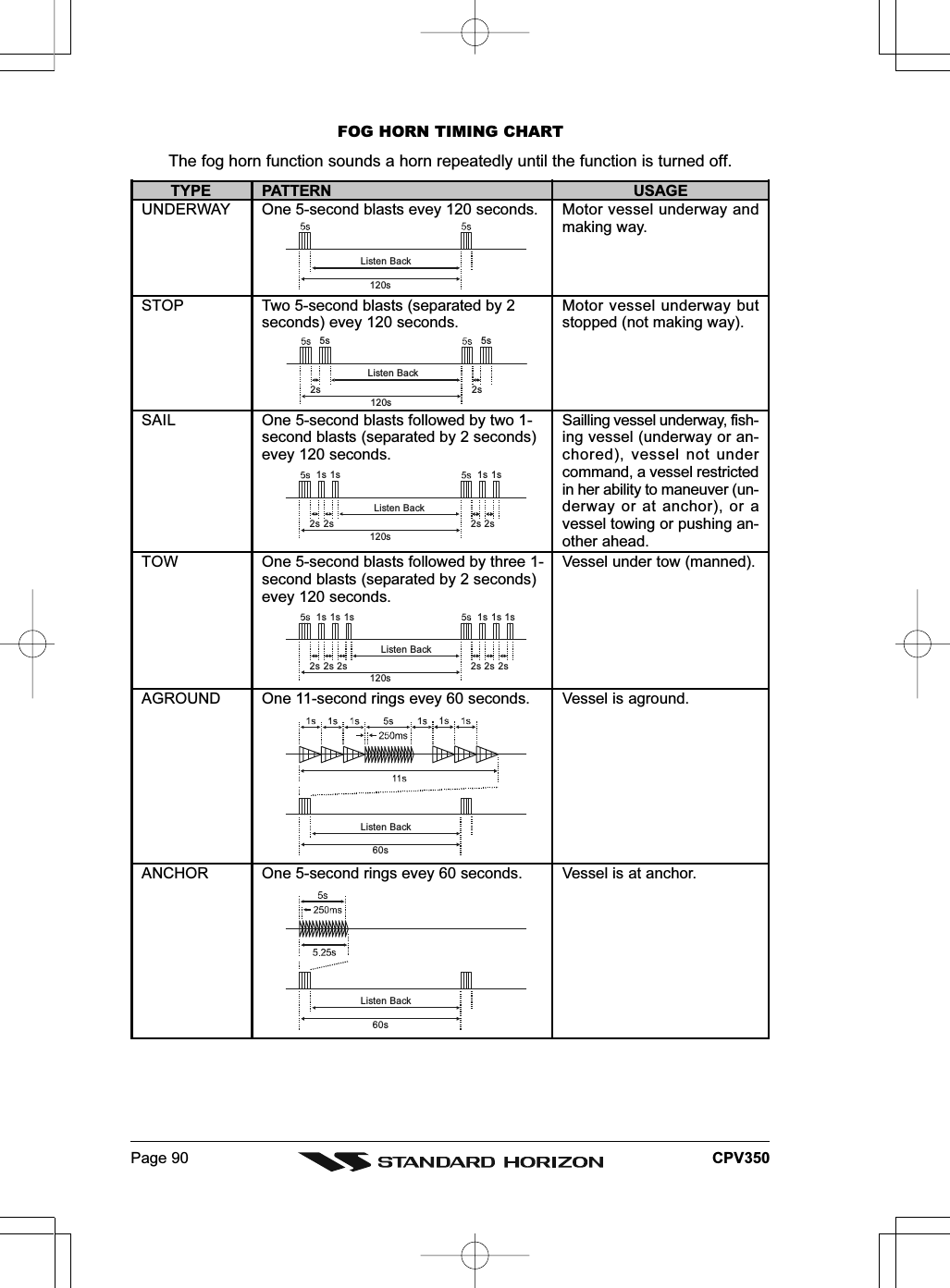
![Page 89CPV35018.12 PA/FOG OPERATIONPA/FOG mode allows the CPV350 to be used as a 30W hailer when an optional STANDARDHORIZON 220SW or 240SW PA horn speaker is installed. When in Hail or FOG mode thePA speaker Listen’s Back (acts as a microphone and amplifies sound to the front panelspeaker) through the PA horn speaker providing two-way communications through the PAhorn speaker.NOTEWhen in PA or FOG mode the CPV350 will receive on the last selected VHF channel beforeentering into the PA or FOG mode and receive DSC calls.PA HAIL mode: PA HAIL mode allows the transceiver to be used as a power hailer whenan optional STANDARD HORIZON 220SW or 240 SW HAIL/PAspeaker is installed. The Hail mode has a listen-back feature providingtwo way communication through the HAIL/PA speaker.FOG HORN mode: Automatic signaling is transmitted through the HAIL/PA horn.18.12.0 Operating the PA HAIL mode1. Press [MENU]. Move the ShuttlePoint knob to highlight PublicAddress and press [ENT].2. Press [PTT] on the microphone to speak through the HAIL/PAspeaker.3. With the [PTT] pressed, rotate the Channel knob to control the PAVolume level. The AF output level can be set from 0 to 30 watts.4. To exit the PA HAIL mode, press [MENU] and move the ShuttlePointknob to highlight Exit Public Address, then press [ENT].5. To adjust the listen back volume, rotate the Channel knob when the [PTT] is notpressed.18.12.1 Operating the FOG HORN modeOperator can select from “Underway,” “Stop,” “Sail,” “Tow,” “Aground,” “Anchor,” “Horn,” or“Siren.” Please refer to next page for FOG Horn Timing Chart.1. Press [MENU]. Move the ShuttlePoint knob to highlight Fog Horn and press [ENT].2. A “Fog Horn” popup window will be displayed, move the ShuttlePoint knobup or down, or turn the Channel knob to select the one of the eight functionsfrom the window.3. Press [ENT].4. On the Horn and Siren modes, press [PTT] on the microphone to activatethe fog signal through the HAIL/PA horn and turn the Channel knob whilethe [PTT] is pressed to control the volume of the horn or siren.5. Rotate the Channel knob to control the AF output level. The AF outputlevel can be set from 0 to 30 watts.6. To exit the FOG HORN mode, press [MENU] and move the ShuttlePointknob to highlight Exit Fog Horn, then press [ENT].7. To adjust the listen back volume, rotate the Channel knob when the [PTT] is notpressed.](https://usermanual.wiki/Yaesu-Musen/30163X3S.USERS-MANUAL-2-OF-2/User-Guide-645731-Page-48.png)
![Page 91CPV35018.12.2 FOG ALERT TONE FrequencyAllows selection of the Frequency for the FOG horn signal. Available selections are “200Hz” through “850 Hz” in 50 Hz steps. The default Alert Tone Frequency is 400 Hz.1. Press [MENU] two times. Move the ShuttlePoint knob to highlight FOG SETUP andpress [ENT] or move the ShuttlePoint knob to the right.2. Press [ENT] or move the ShuttlePoint knob to the right again, move the ShuttlePointknob up or down to select the “100 Hz” digits of the desired tone frequency (“2” through“8”).3. Move the ShuttlePoint knob to the right, then move the ShuttlePoint knob up or downto select the “10 Hz” digits of the desired tone frequency (“0” or “5”).4. Press [ENT] to store the selected setting.5. Press [CLR] until the menu disappears or an easier method is to move the ShuttlePointknob to the left a few times.Figure 18.11.3 - PRIORITY CH menu18.13 INTERCOM OPERATIONConnecting a CMP25 RAM+ or VH-310 handset to the CPV350 allows intercomcommunications. Refer to section “21.2 INTERCOM OPERATION” for CMP25 RAM+Microphone or section “22.2 INTERCOM OPERATION” for VH-310 Handset.1. Press [MENU]. Move the ShuttlePoint knob to highlight Intercom then press [ENT].2. If your CPV350 is equipped with two CMP25 RAM+ Mic’s (or VH-310Handset), “INTERCOM” popup window appears on the display, select thestation you wish to communicate (Ram1, Ram2, or ALL) with the ShuttlePointknob, then press [ENT].3. When the “INTERCOM” is activated, a “INTERCOM” popupwindow is displayed on the CPV350, and “IC” is displayedon the CMP25 RAM+ Mic or VH-310 Handset.4. Press [PTT]. “Talk” will be shown on the display.NOTE: A warning beep will be emitted when the CPV350microphone’s [PTT] is pressed while the RAM+ Mic’s orVH-310 Handset’s [PTT] is pressed.5. Speak slowly and clearly into the microphone, hold themicrophone about 1/2 inch (1.3 cm) away from your mouth.6. When finished, release [PTT].7. To exit the “INTERCOM” mode and return to radio operation mode, press [MENU] andmove the ShuttlePoint knob to highlight Exit Intercom, then press [ENT].(Second Station Mic’s PTT switch is pressed)(CPV350’s PTT switch is pressed)](https://usermanual.wiki/Yaesu-Musen/30163X3S.USERS-MANUAL-2-OF-2/User-Guide-645731-Page-50.png)
![Page 92 CPV35018.14 VOICE SCRAMBLERIf privacy of communications is desired, a CVS2500 voice scrambler (VS) can be installedin the transceiver. Contact your Dealer to have a CVS2500 installed.18.14.0 Setting Up the Voice Scrambler1. Press [MENU] two times. Move the ShuttlePoint knob to highlight RADIO SETUP andpress [ENT] or move the ShuttlePoint knob to the right.2. Move the ShuttlePoint knob to highlight VHF SETTING and press [ENT] or move theShuttlePoint knob to the right.3. Move the ShuttlePoint knob to highlight COMMON CHANNEL SETUP and press [ENT]or move the ShuttlePoint knob to the right.4. Move the ShuttlePoint knob to select the channel group (USA, INTL, or CAN) you wishto setup the Voice Scrambler and press [ENT] or move the ShuttlePoint knob to theright.5. Move the ShuttlePoint knob to highlight CH NO. and press [ENT] or move theShuttlePoint knob to the right.6. Move the ShuttlePoint knob to select the operating channel you wish to setup the VoiceScrambler and press [ENT].7. Move the ShuttlePoint knob to highlight SCRAMBLER and press [ENT] or move theShuttlePoint knob to the right.8. Another popup window will be shown with On and Off, move the ShuttlePoint knob toselect On and press [ENT] or move the ShuttlePoint knob to the right.9. Move the ShuttlePoint knob to highlight SCRAMBLER CODE and press [ENT] or movethe ShuttlePoint knob to the right.10. Move the ShuttlePoint knob to select the desired Scramble Code. The Scramble Codecan be select to 0, 1, 2, or 3.11. To setup the Voice Scramble to another operating channel, repeat steps 5 through 10.12. Press [CLR] until the menu disappears or an easier method is to move the ShuttlePointknob to the left a few times.Figure 18.14.0 - CH EDIT menu](https://usermanual.wiki/Yaesu-Musen/30163X3S.USERS-MANUAL-2-OF-2/User-Guide-645731-Page-51.png)
![Page 95CPV35019.1.1 Programming the MMSIWARNINGUser MMSI can be input only twice. If the user tries to input an MMSI more thantwice, the radio will show the display on the right. If the user needs to change theMMSI more than twice, the transceiver will have to be sent to Factory Service. Referto the section “23.1 FACTORY SERVICE.”1. Press [MENU] two times. Move the ShuttlePoint knob to highlight RADIO SETUP andpress [ENT] or move the ShuttlePoint knob to the right.2. Move the ShuttlePoint knob to highlight DSC SETTINGS and press [ENT] or move theShuttlePoint knob to the right.3. Move the ShuttlePoint knob to highlight USER MMSI and press [ENT] or move theShuttlePoint knob to the right.4. Move the ShuttlePoint knob to the up or down to select the first number of your MMSI,then move the ShuttlePoint knob to the right to step to the next number.5. Repeat step 6 to set your MMSI (up to nine digits).6. When finished programming the number, press the [ENT] to store the number inmemory.7. Press [CLR] until the menu disappears or an easier method is to move the ShuttlePointknob to the left a few times.Figure 19.1 - DSC SETTINGS menu19.2 DSC DISTRESS CALLThe CPV350 is capable of transmitting and receiving DSC Distress messages from all DSCradios. The CPV350 will transmit the Latitude, Longitude of the vessel if the GPS has a fix.19.2.0 Transmitting a DSC Distress CallNOTETo be able to transmit a DSC distress call an MMSI number must be programmed, refer to section“19.1.1 Programming the MMSI.” In order for your ships location to be transmitted a GPS antennamust be connected to the CPV350, refer to section “2.3 MOUNTING THE GPS WASS SMARTANTENNA.”1. Lift the red spring loaded DISTRESS cover and press [DISTRESS]. “DISTRESSALERT” popup window will appear on the display.](https://usermanual.wiki/Yaesu-Musen/30163X3S.USERS-MANUAL-2-OF-2/User-Guide-645731-Page-54.png)
![Page 96 CPV3502. Press and hold [DISTRESS]. The radios display willcount down (3-2-1) and then transmit the Distress call.3. When the distress signal is sent, CH70 and “TX” iconwill briefly appear on the VHF Radio” window in thedisplay. After the message has been sent, the radio willsound a Distress Alarm.4. The transceiver will watch for a DSC acknowledgmenttransmission on CH70 and also receive calls on CH16.5. If an acknowledgement is received, select channel 16and advise your distress situation.6. If no acknowledgment is received, the distress call is repeated in4 minute intervals until a DSC acknowledgment is received.7. When a DSC Distress acknowledgment is received, a distressalarm sounds. The radio automatically switched to channel 16,and display shows the MMSI of the ship responding to yourdistress.RECEIVED ACK: acknowledgment signal is received.RECEIVED RLY: relay signal is received from anothervessel or coast station.8. To cancel the DSC distress alarm signal from the speaker,press any key.Transmitting a DSC Distress Call with Nature of DistressThe CPV350 is capable of transmitting a DSC Distress Call with the following “Nature ofDistress” categories: Undesignated, Fire, Flooding, Collision, Grounding, Capsizing,Sinking, Adrift, Abandoning, Piracy, MOB.1. Lift the red spring loaded DISTRESS cover and press[DISTRESS]. The “DISTRESS ALERT” popup windowwill appear on the display.2. Move the ShuttlePoint knob to the up or down or turn theChannel knob to select the desired nature of distresscategory.3. Press and hold [DISTRESS]. The radios display willcount down (3-2-1) and then transmit the Distress call.4. When the distress signal is sent, CH70 and “TX” iconwill appear on the “VHF Radio” window in the display. After themessage has been sent, the radio will sound a Distress Alarm.5. The transceiver will watch for a DSC acknowledgment transmissionon CH70 and also receive calls on CH16.6. If an acknowledgement is received, select channel 16 and adviseyour distress situation.7. If no acknowledgment is received, the distress call is repeatedin 4-minute intervals until a DSC acknowledgment is received.8. When a DSC Distress acknowledgment is received, a distressalarm sounds. The radio automatically switches to channel16, and display shows the MMSI of the ship responding toyour distress.RECEIVED ACK: acknowledgment signal is received.RECEIVED RLY: relay signal is received from another vessel or coast station.9. To cancel the DSC distress alarm signal from the speaker, press any key.](https://usermanual.wiki/Yaesu-Musen/30163X3S.USERS-MANUAL-2-OF-2/User-Guide-645731-Page-55.png)
![Page 97CPV350Cancel a DSC Distress CallIf a DSC Distress call was sent by error the CPV350allows you to send a message to other vessels to cancelthe Distress Call that was made in error.Press [CLR], then press [ENT].19.2.1 Receiving a DSC Distress Call1. When a DSC Distress call is received, an emergency alarmsounds.2. The CPV350 automatically switches to channel 16, and“RECEIVED DISTRESS ALERT” popup window is shownon the display.3. Press any key to stop the alarm.NOTEYou must continue monitoring channel 16 as a coast station may require assistance in the rescueattempt.19.3 ALL SHIPS CALLThe All Ships Call function allows contact to be established with other vessel stationswithout having their ID in the individual calling directory. Also, priority for the call can bedesignated as Urgency or Safety.URGENCY Call:This type of call is used when a vessel may not truly be in distress, but havea potential problem that may lead to a distress situation. This call is thesame as saying PAN PAN PAN on channel 16.SAFETY Call: Used to transmit boating safety information to other vessels. This messageusually contains information about an overdue boat, debris in the water,loss of a navigation aid or an important meteorological message. This callis the same as saying Securite, Securite, Securite.19.3.0 Transmitting an All Ships Call1. Press [CALL]. The “DSC Operation” menu soft keys appear below the display.2. Press [ALL SHIPS] and a “ALL SHIPS CALL” popup windowwill be shown on the display.3. Move the ShuttlePoint knob up or down or turn the Channelknob to select the call (Urgency or Safety), then press [ENT].4. Press [ENT] again to transmit the selected type of all ships DSC call.5. After the ALL SHIPS CALL is transmitted, the transceiver will switchto CH16.6. Listen to the channel to make sure it is not busy, then key themicrophone and say PAN PAN PAN or “Securite, Securite, Securite”depending on the priority of the call. Say your call sign and announcethe channel you wish to switch to for communications.](https://usermanual.wiki/Yaesu-Musen/30163X3S.USERS-MANUAL-2-OF-2/User-Guide-645731-Page-56.png)
![Page 98 CPV35019.3.1 Receiving an All Ships Call1. When an all ships call is received, an emergency alarm sounds.2. The radio will automatically change to channel 16, and a “RCEIVEDDSC CALL” popup window will be shown on the display to see theMMSI of the vessel transmitting the All Ships Call.3. Press any key to stop the alarm.4. Monitor channel 16 or traffic channel until the URGENCY voicecommunication is completed.19.4 INDIVIDUAL CALLThis feature allows the CPV350 to contact another vessel with a DSC VHF radio andautomatically switch the receiving radio to a desired communications channel. This featureis similar to calling a vessel on CH16 and requesting to go to another channel (switchingto the channel is private between the two stations).19.4.0 Setting up the Individual / Position Call DirectoryThe CPV350 has a DSC directory that allows you to store a vessel or person’s name andthe MMSI number associated with vessels you wish to transmit Individual calls, PositionRequests and Position Send transmissions. The CPV350 can store up to 56 MMSI into theIndividual directory.To transmit an Individual call you must program this directory with information of the personsyou wish to call, similar to a cellular phones telephone directory.1. Press [MENU] two times. Move the ShuttlePoint knob to highlight RADIO SETUP andpress [ENT] or move the ShuttlePoint knob to the right.2. Move the ShuttlePoint knob to highlight DSC SETTINGS and press [ENT] or move theShuttlePoint knob to the right.3. Move the ShuttlePoint knob to highlight INDIVIDUAL DIRECTORY and press [ENT] ormove the ShuttlePoint knob to the right.4. Move the ShuttlePoint knob to highlight NEW then press [ENT].5. Move the ShuttlePoint knob to up or down to scroll through the first letter of the nameof the vessel or person you want to reference in the directory.6. Move the ShuttlePoint knob to the right to store the first letter in the name and step tothe next letter to the right.7. Repeat step 5 and 6 until the name is complete. The name can consist of up to elevencharacters.8. After the eleventh letter or space has been entered, press [ENT] to advance to the MMSInumber entry.9. Move the ShuttlePoint knob to up or down to scroll through numbers, 0-9 to enter thedesired number and move the ShuttlePoint knob to the right to move one space to theright. Repeat this procedure until all nine space of the MMSI number are entered.10. If a mistake was made entering in the MMSI number move the ShuttlePoint knob to theleft until the wrong number is selected, then move the ShuttlePoint knob to up or downto correct the entry.11. To store the data entered, press [ENT] two times.](https://usermanual.wiki/Yaesu-Musen/30163X3S.USERS-MANUAL-2-OF-2/User-Guide-645731-Page-57.png)
![Page 99CPV35012. To enter another individual address, repeat steps 4 through 11.13. Press [CLR] until the menu disappears.Figure 19.4.0 - INDIVIDUAL DIRECTORY menu19.4.1 Setting up Individual ReplyAllows setting up the radio to automatically (default setting) or manually respond to a DSCIndividual call requesting you to switch to a working channel for voice communications.When Manual is selected the MMSI of the calling vessel is shown allowing you to see whois calling. This function is similar to caller id on a cellular phone.1. Press [MENU] two times. Move the ShuttlePoint knob to highlight RADIO SETUP andpress [ENT] or move the ShuttlePoint knob to the right.2. Move the ShuttlePoint knob to highlight DSC SETTINGS and press [ENT] or move theShuttlePoint knob to the right.3. Move the ShuttlePoint knob to highlight INDIVIDUAL REPLY and press [ENT] or movethe ShuttlePoint knob to the right.4. A popup window will be shown with Manual and Automatic, move the ShuttlePoint knobto the desired selection and press [ENT] or move the ShuttlePoint knob to the right.5. Press [CLR] until the menu disappears or an easier method is to move the ShuttlePointknob to the left a few times.Figure 19.4.0 - INDIVIDUAL REPLY menu](https://usermanual.wiki/Yaesu-Musen/30163X3S.USERS-MANUAL-2-OF-2/User-Guide-645731-Page-58.png)
![Page 100 CPV35019.4.2 Setting up the Individual/Group Call RingerWhen an Individual Call or Group Call is received the radio will produce a ringing tone for3 minutes. This selection allows ringer time to be changed.1. Press [MENU] two times. Move the ShuttlePoint knob to highlight RADIO SETUP andpress [ENT] or move the ShuttlePoint knob to the right.2. Move the ShuttlePoint knob to highlight DSC SETTINGS and press [ENT] or move theShuttlePoint knob to the right.3. Move the ShuttlePoint knob to highlight RINGER and press [ENT] or move theShuttlePoint knob to the right.4. Another popup window will be shown, move the ShuttlePoint knob to the desired ringingtime of a Individual Call and press [ENT] or move the ShuttlePoint knob to the right.5. Press [CLR] until the menu disappears or an easier method is to move the ShuttlePointknob to the left a few times.Figure 19.4.2 - RINGER menuThe CPV350 has the capability to turn off the ringer for Individual, Group and DSC pollingcalls.1. Press [MENU] two times. Move the ShuttlePoint knob to highlight RADIO SETUP andpress [ENT] or move the ShuttlePoint knob to the right.2. Move the ShuttlePoint knob to highlight DSC SETTINGS and press [ENT] or move theShuttlePoint knob to the right.3. Move the ShuttlePoint knob to highlight RINGER OUTPUT and press [ENT] or movethe ShuttlePoint knob to the right.4. Move the ShuttlePoint knob to select INDIVIDUAL if you wish to disable the IndividualCall ringer, move the ShuttlePoint knob to GROUP or Polling ringer and press [ENT]or move the ShuttlePoint knob to the right.5. Another popup window will be shown with On and Off, move the ShuttlePoint knob toselect Off and press [ENT] or move the ShuttlePoint knob to the right6. Press [CLR] until the menu disappears or an easier method is to move the ShuttlePointknob to the left a few time.If you wish to return to enabling the ringer tone, just repeat the above procedure, movingthe ShuttlePoint knob to select On in step “5” above.](https://usermanual.wiki/Yaesu-Musen/30163X3S.USERS-MANUAL-2-OF-2/User-Guide-645731-Page-59.png)
![Page 101CPV350Figure 19.4.2 - RINGER OUTPUT menu19.4.3 Transmitting an Individual CallThis feature allows the user to contact another vessel with a DSC radio. This feature issimilar to calling a vessel on CH16 and requesting to go to another channel.Using the Individual Calling directoryTo use this method the CPV350 must be pre-programmed with MMSI numbers of vesselsyou wish to call (similar to programming in telephone numbers into a cell phone. Refer tosection “19.5.1 Setting up the Individual / Position Call Directory.”1. Press [CALL]. The “DSC Operation” menu soft keys appear at the bottom edge of thedisplay.2. Press [INDIVIDUAL] and the “DIRECTORY” popup window on thedisplay.3. Move the ShuttlePoint knob to the up or down or turn the Channel knobto select the “Individual” you want to contact.4. Press [ENT], then turn the Channel knob to select the operating channelyou want to communicate on and press [ENT].5. Press [ENT] again to transmit the individual DSC Call or press the [CLR]key to cancel the call. After INDIVIDUAL CALL is transmitted, thetransceiver will wait 8 seconds for the acknowledgment. If the replysignal is not received, the transceiver will transmit again.6. After the second INDIVIDUAL CALL is transmitted, if the reply signalis not received, the display will be as shown in the illustration on theright. To send the call again, press [ENT].7. When an individual call acknowledgment is received, the establishedchannel is automatically changed to the channel which is selected onstep 3 above and a ringing tone sounds.8. Press any key to listen to the channel to make sure it is not busy, thenkey the microphone and call the other vessel you desire to communicatewith.](https://usermanual.wiki/Yaesu-Musen/30163X3S.USERS-MANUAL-2-OF-2/User-Guide-645731-Page-60.png)
![Page 102 CPV350Manual Calling a Individual MMSIYou may enter an MMSI number manually to contact without Setting up the IndividualDirectory.1. Press [CALL]. The “DSC Operation” menu soft keys will appear at underneath thedisplay.2. Press [INDIVIDUAL] to show the “DIRECTORY” popup window on the display.3. Move the ShuttlePoint knob to the up or down or turn the Channel knobto select “MANUAL,” then press the [ENT] key show the “MMSI INPUT”window on the display.4. Move the ShuttlePoint knob to up or down to scroll through numbers, 0-9 to enter the desired number and move the ShuttlePoint knob to the rightto move one space to the right. Repeat this procedure until all nine spaceof the MMSI number are entered.5. If a mistake was made entering in the MMSI number move the ShuttlePoint knob to theleft until the wrong number is selected, then move the ShuttlePoint knob to up or downto correct the entry.6. When finished entering the MMSI number, press the [ENT].7. Turn channel knob to select the operating channel you want tocommunicate on and press [ENT].8. Press [ENT] again to transmit the individual DSC Call or press the[CLR] key to cancel the call.9. After INDIVIDUAL CALL is transmitted, the transceiver will wait 8seconds for the acknowledgment. If the reply signal is not received,the transceiver will transmit again.10. After the second INDIVIDUAL CALL is transmitted, if the reply signalis not received, the display will be as shown in the illustration on theright. To send the call again, press [ENT] or to exit the mode, press[CLR].11. When an individual call acknowledgment is received, the established channel isautomatically changed to the channel which is selected on step 7 above and a ringingtone sounds.12. Press any key to listen to the channel to make sure it is not busy, then key themicrophone and call the other vessel you desire to communicate with.19.4.4 Receiving an Individual CallWhen the CPV350 receives an individual call, by default the CPV350 automaticallytransmits an acknowledgement before switching to the requested channel. The CPV350can be set so the CPV350 prompts you to manually send a reply, refer to section “19.4.1Setting up Individual Reply.”1. When an individual call is received, an individual call ringing alarmsounds.2. The radio automatically switches to the requested channel, andappear “RCEIVED DSC CALL” popup window on the display tosee the MMSI of the vessel transmitting the Individual Call.3. Press any key to stop the alarm.4. Press [PTT] on the microphone and talk to the calling ship.](https://usermanual.wiki/Yaesu-Musen/30163X3S.USERS-MANUAL-2-OF-2/User-Guide-645731-Page-61.png)
![Page 103CPV35019.5 CALL WAITING DIRECTORYThe CPV350 logs received distress calls and individual calls. The DSC Call Waiting featureis similar to an answer machine where calls are this recorded logs for review. When a callis logged while the radio is set on the DSC Standby function, a message will appear on theLCD. The CPV350 can be memorized up to the latest 23 Distress and up to the latest 56Individual Calls.19.5.0 Enabling the Call Waiting FeatureFollow the steps below to enable or disable the Call Waiting feature.1. Press [MENU] two times. Move the ShuttlePoint knob to highlight RADIO SETUP andpress [ENT] or move the ShuttlePoint knob to the right.2. Move the ShuttlePoint knob to highlight DSC SETTINGS and press [ENT] or move theShuttlePoint knob to the right.3. Move the ShuttlePoint knob to highlight INDIVIDUAL REPLY MESSAGE and press[ENT] or move the ShuttlePoint knob to the right.4. A popup window will be shown with Able to Comply or Unable to Comply, move theShuttlePoint knob to the desired selection and press [ENT] or move the ShuttlePointknob to the right.5. Press [CLR] until the menu disappears or an easier method is to move the ShuttlePointknob to the left a few times.Figure 19.5.0 - INDIVIDUAL REPLY MESSAGE menu19.5.1 Reviewing Received Calls Logged into the Call WaitingDirectory1. Press [CALL]. The “DSC Operation” menu soft keys will appear at the bottom edge ofthe display.2. Press [NEXT] to show additional soft keys.3. Press [DSC LOG] to appear “DSC LOG” popup window on the display.4. Move the ShuttlePoint knob to the up or down or turn the Channel Knob toselect the category (DISTRESS or DSC CALL) you want to review and callback.](https://usermanual.wiki/Yaesu-Musen/30163X3S.USERS-MANUAL-2-OF-2/User-Guide-645731-Page-62.png)
![Page 104 CPV3505. Press [ENT], to review details for the selected category.6. Move the ShuttlePoint knob to the up or down to select the station you want to reviewand call back, then press [RESEND] to call the selected station.Figure 19.5.1 - DSC CALL LOG list19.5.2 To Delete the Received Log from the “DSC Log” Directory1. Press [CALL]. The “DSC Operation” menu Tabs will appear at the bottom edge of thedisplay.2. Press [NEXT] to change the menu Tabs to another Tabs.3. Press [DSC LOG] to appear “DSC LOG” popup window on the display.4. Move the ShuttlePoint knob to the up or down or turn the Channel knob to select thecategory (DISTRESS or DSC CALL) to be deleted.5. Press [ENT], to review details for the selected category.6. Move the ShuttlePoint knob to the up or down to select the station you want to delete,then press [DELETE] to delete from the DSC Log.7. Press [CLR] until the menu disappears or an easier method is to move the ShuttlePointknob to the left a few times.](https://usermanual.wiki/Yaesu-Musen/30163X3S.USERS-MANUAL-2-OF-2/User-Guide-645731-Page-63.png)
![Page 105CPV35019.6 GROUP CALLThis feature allows the user to contact a group of specific vessels (example members of ayacht club) using DSC radios with Group call function to automatically switch to a desiredchannel for voice communications.19.6.0 Setting up a Group CallFor this function to operate the same Group MMSI must be programmed into all the DSCVHF radios within the group of vessels that will be using this feature. The group MMSI isa 9 digit (first digit permanently set to “0”) number that will allow other radios to call yourvessel along with others to automatically switch to a working channel for voicecommunications. This function is very useful for yacht clubs and vessels traveling togetherthat want to collectively make announcements on a predetermined channel.1. Press [MENU] two times. Move the ShuttlePoint knob to highlight RADIO SETUP andpress [ENT] or move the ShuttlePoint knob to the right.2. Move the ShuttlePoint knob to highlight DSC SETTINGS and press [ENT] or move theShuttlePoint knob to the right.3. Move the ShuttlePoint knob to highlight GROUP DIRECTORY then press [ENT].4. Move the ShuttlePoint knob to highlight NEW then press [ENT].5. Move the ShuttlePoint knob to up or down to scroll through the first letter of the nameof the vessel or person you want to reference in the group MMSI number.6. Move the ShuttlePoint knob to the right to store the first letter in the name and step tothe next letter to the right.7. Repeat step 7 and 8 until the name is complete. The name can consist of up to elevencharacters.8. After the eleventh letter or space has been entered, press [ENT] to advance to the groupMMSI number entry.9. Move the ShuttlePoint knob to up or down to scroll through numbers, 0-9 to enter thedesired number and move the ShuttlePoint knob to the right to move one space to theright (first digit permanently set to “0”). Repeat this procedure until all nine space of theMMSI number are entered.10. If a mistake was made entering in the MMSI number move the ShuttlePoint knob to theleft until the wrong number is selected, then move the ShuttlePoint knob to up or downto correct the entry.11. To store the data entered, press [ENT] two times.12. To enter another group MMSI, repeat steps 6 through 11.13. Press [CLR] until the menu disappears.Figure 19.6.0 - GROUP DIRECTORY menu](https://usermanual.wiki/Yaesu-Musen/30163X3S.USERS-MANUAL-2-OF-2/User-Guide-645731-Page-64.png)
![Page 106 CPV35019.6.1 Transmitting a Group CallUsing the Group calling directory1. Press [CALL]. The “DSC Operation” menu Tabs will appear at the bottom edge of thedisplay.2. Press [GROUP] to show “DIRECTORY” popup window onthe display.3. Move the ShuttlePoint knob to the up or down or turn theChannel knob to select the “Group” you want to contact.4. Press [ENT], then turn the Channel knob to select theoperating channel you want to communicate on and press[ENT].5. Press [ENT] again to transmit the Group Call signal.6. After the GROUP CALL is transmitted, all the radios in the group willswitch to the designated channel.7. Listen to the channel to make sure it is not busy, then key themicrophone and call the other vessels you desire to communicatewith.Manual Calling a Group MMSI numberYou may enter a Group MMSI number manually to contact without Setting up the Group callnumber.1. Press [CALL]. The “DSC Operation” menu Tabs will appear at the bottom edge of thedisplay.2. Press [GROUP] to show “DIRECTORY” popup window on the display.3. Move the ShuttlePoint knob to the up or down or turn the Channel knobto select “MANUAL,” then press [ENT] to show the “MMSI INPUT” windowon the display.4. Move the ShuttlePoint knob to up or down to scroll through numbers, 0-9 to enter the desired number and move the ShuttlePoint knob to the rightto move one space to the right (first digit permanently set to “0”). Repeat this procedureuntil all nine space of the MMSI number are entered.5. If a mistake was made entering in the MMSI number move the ShuttlePoint knob to theleft until the wrong number is selected, then move the ShuttlePoint knob to up or downto correct the entry.6. When finished entering the MMSI number, press the [ENT] key.7. Turn the Channel knob to select the operating channel you want tocommunicate on and press [ENT].8. Press [ENT] again to transmit the Group Call signal.9. After the GROUP CALL is transmitted, all the radios in the group willswitch to the designated channel.10. Listen to the channel to make sure it is not busy, then key themicrophone and call the other vessels you desire to communicatewith.](https://usermanual.wiki/Yaesu-Musen/30163X3S.USERS-MANUAL-2-OF-2/User-Guide-645731-Page-65.png)
![Page 107CPV35019.6.2 Receiving a Group Call1. When a group call is received, the CPV350 will produce a ringingalarm sound.2. The radio automatically switches to the requested channel, andappear “RECEIVED DSC CALL” popup window on the display tosee the MMSI of the vessel transmitting the Group Call.3. Press any key to stop the alarm.4. Monitor the channel for the person calling the Group for amessage.5. If you want to respond, monitor the channel to make sure it is clear, then press [PTT]on the microphone and talk to the calling ship(s).19.7 POSITION REQUESTAdvancements in DSC have made it possible to poll the location of another vessel and showthe position of that vessel on the display of the CPV350 making it easy to navigate to thelocation of the polled vessel. This is a great feature for anyone wanting to know the positionof another vessel. For example your buddy that is catching fish, or finding the location of aperson you are cruising with.NOTEThe other vessel must have an operating GPS receiver connected to its DSC transceiver and mustnot have its transceiver set to deny position requests. (Refer the section “19.4.0 Setting up theIndividual / Position Call Directory” to enter information into the individual directory).19.7.0 Setting up Position ReplyThe CPV350 can be set up to automatically or manually send your position to anothervessel. This selection is important if you are concerned about someone polling the positionof your vessel that you may not want to. In the manual mode you will see the MMSI orpersons name shown on the display allowing you to choose to send your position to therequesting vessel.1. Press [MENU] two times. Move the ShuttlePoint knob to highlight RADIO SETUP andpress [ENT] or move the ShuttlePoint knob to the right.2. Move the ShuttlePoint knob to highlight DSC SETTINGS and press [ENT] or move theShuttlePoint knob to the right.3. Move the ShuttlePoint knob to highlight POS REQUEST REPLY and press [ENT] ormove the ShuttlePoint knob to the right.4. Another popup window will be shown with Manual or Automatic, move the ShuttlePointknob to the desired selection and press [ENT] or move the ShuttlePoint knob to the right.In Manual mode, the display of the CPV350 will show who is requesting the position.In Automatic mode, after a DSC POS Request is received, the radio will automaticallytransmit your vessels position.5. Press [CLR] until the menu disappears or an easier method is to move the ShuttlePointknob to the left a few times.](https://usermanual.wiki/Yaesu-Musen/30163X3S.USERS-MANUAL-2-OF-2/User-Guide-645731-Page-66.png)
![Page 108 CPV350Figure 19.7.0 - POS REQUEST REPLY menuThe CPV350 has the capability to turn off the Position Request ringer.1. Press [MENU] two times. Move the ShuttlePoint knob to highlight RADIO SETUP andpress [ENT] or move the ShuttlePoint knob to the right.2. Move the ShuttlePoint knob to highlight DSC SETTINGS and press [ENT] or move theShuttlePoint knob to the right.3. Move the ShuttlePoint knob to highlight RINGER OUTPUT and press [ENT] or movethe ShuttlePoint knob to the right.4. Move the ShuttlePoint knob to select POLLING and press [ENT] or move theShuttlePoint knob to the right.5. A popup window will be shown with On or Off, move the ShuttlePoint knob to select Offand press [ENT] or move the ShuttlePoint knob to the right.6. Press [CLR] until the menu disappears or an easier method is to move the ShuttlePointknob to the left a few times.If you wish to return to enabling the ringer tone, just repeat the above procedure, movingthe ShuttlePoint knob to select On in step “5” above.Figure 19.7.0 - RINGER OUTPUT menu19.7.1 Transmitting a Position Request to Another VesselUsing the Individual directory to make a Position request1. Press the [CALL] key. The “DSC Operation” menu soft keys will appear below thedisplay.](https://usermanual.wiki/Yaesu-Musen/30163X3S.USERS-MANUAL-2-OF-2/User-Guide-645731-Page-67.png)
![Page 109CPV3502. Press [POSITION REQUEST] to show the “DIRECTORY”popup window on the display.3. Move the ShuttlePoint knob up or down or turn the Channelknob to select the “Individual” you want to poll the location ofthe vessel and show the position of that vessel, then press[ENT].4. Press [ENT] again to transmit the position request DSC call.5. When the CPV350 receives the position from the polled vessel itis shown on the GPS Chart of the page.6. If the CPV350 does not receive a reply, the display will be asshown in the illustration on the right. To send again, press [ENT].Manual sending a position request callYou may enter an MMSI number manually to contact without Setting up the Individual /Position Call Directory.1. Press [CALL]. The “DSC Operation” menu Tabs will appear at the bottom edge of thedisplay.2. Press [POSITION REQUEST] to show “DIRECTORY” popup window onthe display.3. Move the ShuttlePoint knob to the up or down or turn the Channel knobto select “MANUAL,” then press [ENT] to appear “MMSI INPUT” windowon the display.4. Move the ShuttlePoint knob to up or down to scroll through numbers, 0-9 to enter the desired number and move the ShuttlePoint knob tothe right to move one space to the right. Repeat this procedure untilall nine space of the MMSI number are entered.5. If a mistake was made entering in the MMSI number move theShuttlePoint knob to the left until the wrong number is selected,then move the ShuttlePoint knob to up or down to correct the entry.6. When finished entering the MMSI number, press [ENT].7. Press [ENT] to transmit the position request DSC call.8. When the CPV350 receives the position from the polled vessel itis shown on the the GPS Chart of the radio display.9. If the CPV350 does not receive a reply, the display will be asshown in the illustration on the right. To send again, press [ENT].](https://usermanual.wiki/Yaesu-Musen/30163X3S.USERS-MANUAL-2-OF-2/User-Guide-645731-Page-68.png)
![Page 110 CPV35019.7.2 Receiving a Position RequestWhen a position request call is received from another vessel, a ringingalarm will sound and POS REQUEST will be shown in the LCD.Operation and transceiver function differs depending on “POSREQUEST REPLY” in the “DSC Setup” menu setting.Automatically reply:1. When a position request call is received, a calling alarm sounds 4 times. Then requestedposition coordinates are transmitted automatically to the vessel requesting your vesselsposition.2. To exit from position request display, press any key.Manually reply:1. When a position request call is received from another vessel, the “RECEIVED DSCCALL” window will open.2. Press [ENT] to transmit your position to the requesting vessel and exit from positionrequest display. Press [CLR] to exit from position request display without the transmittingyour position (No Reply).19.8 POSITION SENDThe feature is similar to Position Request, however instead of requesting a position ofanother vessel this function allows you to send your position to another vessel.19.8.0 Setting up a Position Send RingerThe CPV350 has the capability to turn off the Position Send ringer.1. Press [MENU] two times. Move the ShuttlePoint knob to highlight RADIO SETUP andpress [ENT] or move the ShuttlePoint knob to the right.2. Move the ShuttlePoint knob to highlight DSC SETTINGS and press [ENT] or move theShuttlePoint knob to the right.3. Move the ShuttlePoint knob to highlight RINGER OUTPUT and press [ENT] or movethe ShuttlePoint knob to the right.4. Move the ShuttlePoint knob to select POS SEND and press [ENT] or move theShuttlePoint knob to the right.5. A popup window will be shown with On or Off, move the ShuttlePoint knob to select Offand press [ENT] or move the ShuttlePoint knob to the right.6. Press [CLR] until the menu disappears or an easier method is to move the ShuttlePointknob to the left a few times.To enable the ringer, repeat the above procedure, moving the ShuttlePoint knob to selectOn in step “5” above.](https://usermanual.wiki/Yaesu-Musen/30163X3S.USERS-MANUAL-2-OF-2/User-Guide-645731-Page-69.png)
![Page 111CPV350Figure 19.8.0 - RINGER OUTPUT menu19.8.1 Transmitting a DSC Position Send CallPre-Programmable CallingUsing the Individual directory to transmit a position send call.1. Press [CALL]. The “DSC Operation” menu Tabs will appear at the bottom edge of thedisplay.2. Press [POSITION SEND] to show “DIRECTORY” popupwindow on the display.3. Move the ShuttlePoint knob to the up or down or turn theChannel knob to select the “Individual” you want to contact,then press [ENT].4. Press [ENT] again to send your position to the selected vessel.Manual Calling1. Press [CALL]. The “DSC Operation” menu soft keys appear below the display.2. Press [POSITION REQUEST] to show “DIRECTORY” popup window onthe display.3. Move the ShuttlePoint knob to the up or down or turn the Channel knobto select MANUAL, then press [ENT] to appear “MMSI INPUT” popupwindow on the display.4. Move the ShuttlePoint knob to up or down to scroll through numbers, 0-9 to enter the desired number and move the ShuttlePoint knob to theright to move one space to the right. Repeat this procedure until allnine space of the MMSI number are entered.5. If a mistake was made entering in the MMSI number move theShuttlePoint knob to the left until the wrong number is selected, thenmove the ShuttlePoint knob to up or down to correct the entry.6. When finished entering the MMSI number, press [ENT].7. Press [ENT] again to send your position to the selected vessel.](https://usermanual.wiki/Yaesu-Musen/30163X3S.USERS-MANUAL-2-OF-2/User-Guide-645731-Page-70.png)
![Page 112 CPV35019.8.2 Receiving a DSC Position Send CallWhen another vessel transmits their location to the CPV350, the following will happen:1. When the call is received, a ringing sound will be produced and the“RECEIVED DSC CALL” popup window will open.2. Press the any key to stop the alarm.3. Press [ENT] to shows the position of the calling vessel on the GPSChart of the radio display.](https://usermanual.wiki/Yaesu-Musen/30163X3S.USERS-MANUAL-2-OF-2/User-Guide-645731-Page-71.png)
![Page 113CPV35020. RADIO SETUP20.0 CHANNEL NAME CHANGEThis selection allows you to customize the name of a channel from the default name.1. Press [MENU] two times. Move the ShuttlePoint knob to highlight RADIO SETUP andpress [ENT] or move the ShuttlePoint knob to the right.2. Move the ShuttlePoint knob to highlight VHF SETTING and press [ENT] or move theShuttlePoint knob to the right.3. Move the ShuttlePoint knob to highlight COMMON CHANNEL SETUP and press [ENT]or move the ShuttlePoint knob to the right.4. Move the ShuttlePoint knob to select the channel group (USA, INTL, or CAN) you wishto change the channel name and press [ENT] or move the ShuttlePoint knob to the right.5. Move the ShuttlePoint knob to highlight CH NO. and press [ENT] or move theShuttlePoint knob to the right.6. Move the ShuttlePoint knob to select the operating channel you wish change thechannel name and press [ENT].7. Move the ShuttlePoint knob to highlight NAME and press [ENT] or move the ShuttlePointknob to the right.8. Move the ShuttlePoint knob to up or down to scroll through the first character (letter,number, or symbol) of the channel name.9. Move the ShuttlePoint knob to the right to enter the first character and step to the nextcharacter to the right.10. 7. Repeat step 8 and 9 until the name is complete. The name can consist of up to twelvecharacters.11. Press [CLR] until the menu disappears or an easier method is to move the ShuttlePointknob to the left a few times.Figure 20.0 - CH EDIT menu](https://usermanual.wiki/Yaesu-Musen/30163X3S.USERS-MANUAL-2-OF-2/User-Guide-645731-Page-72.png)
![Page 114 CPV35020.1 UNIT NAMEThis selection allows you to provide the name to the radio and optional RAM+ or VH-310Handset when connected.1. Press [MENU] two times. Move the ShuttlePoint knob to highlight RADIO SETUP andpress [ENT] or move the ShuttlePoint knob to the right.2. Move the ShuttlePoint knob to highlight VHF SETTING and press [ENT] or move theShuttlePoint knob to the right.3. Move the ShuttlePoint knob to highlight UNIT NAME and press [ENT] or move theShuttlePoint knob to the right.4. Move the ShuttlePoint knob to select the Unit (MAIN, RAM1, or RAM2) to be named andpress [ENT] or move the ShuttlePoint knob to the right.5. Move the ShuttlePoint knob to up or down to scroll through the first letter of the unitname.6. Move the ShuttlePoint knob to the right to enter the first character and step to the nextletter to the right.7. Repeat step 5 and 6 until the name is complete. The name can consist of up to twelvecharacters.8. Press [CLR] until the menu disappears or an easier method is to move the ShuttlePointknob to the left a few times.Figure 20.1 - UNIT NAME menu](https://usermanual.wiki/Yaesu-Musen/30163X3S.USERS-MANUAL-2-OF-2/User-Guide-645731-Page-73.png)
![Page 115CPV35021. ENHANCED RAM+ MIC OPERATIONWhen the RAM+ microphone is connected to the CPV350, most VHF, DSC, and setupmenus can be remotely operated. The RAM+ Mic is supplied with 23 feet (7 m) of routingcable and can be extended up to 70 feet (21 m) using three 23 feet extension cables modelCT-100. The intercom operation can be used between the RAM+ Mic and the transceiver.21.0 RAM+ MIC CONTROLSSQUELCH CONTROL (SQL)Activates the squelch adjusting mode.Press this key to activate the squelch adjusting mode. Press the microphone’s [] or []key to adjust the squelch.When this key is pressed and held down for 1 second or more, the squelch is turned off.VOLUME KEY (VOL)Activates the volume adjusting mode.Press this key to activate the volume adjusting mode. Press the microphone’s [] or []to adjust the volume.POWER SWITCH (PWR)Press and hold down this key to turn to the transceiver and RAM+ Mic on and off.PTT (Push-To-Talk) SWITCHActivates transmission.[H/L] KEYToggles between high and low power. When the [H/L] key is pressed while the transceiveris on channel 13 or 67, the power will temporarily switch from LO to HI power until the PTTis released. The [H/L] key does not function on transmit inhibited and low power onlychannels.[](UP)/[](DOWN) KEYThese keys are used to select channels, adjust the volume and squelch level, and to choosethe item selection of different functions (such as the DSC operation). In many ways, thesekeys emulate the function of the transceiver’sChannel knob.[16/9] KEYImmediately recalls channel 16 from any channel location. Holding down this key recallschannel 9. Pressing the [16/9] key reverts to the previous selected working channel.Secondary usePlease see secondary use for the [WX] and [MEM] key.[SCAN] Key1. Starts and stops scanning of programmed channels.2. If held while the [UP()] or [DOWN()] key on the microphone are pressed, the radiowill show the channels programmed in scan memory. This function will not work if theunit is scanning.NOTEThe priority channel by default is Channel 16, however the priority channel can be changed. Toselect a different priority channel refer to section “18.11.3 Priority Channel Set.”](https://usermanual.wiki/Yaesu-Musen/30163X3S.USERS-MANUAL-2-OF-2/User-Guide-645731-Page-74.png)
![Page 116 CPV350[CALL/SET] KeyThe [CALL/SET] key functions as the enter key.Secondary usePress the [CALL/SET] key to access the DSC OPERATIONmenu.Press and hold the [CALL/SET] key to access the SETUPmenu.[DW] KeyWatches for a transmission on CH16 and another selectedchannel until either signal is received. (Dual watch)Secondary usePress and hold [DW] key, intercom operation will operatebetween radio and RAM+ Mic.[NAV] KeyPress this key, when connected to the GPS receiver, theLCD displays Position Data and Time from the GPS.[WX] KeyImmediately recalls the previously selected US NOAAweather channel from any channel location.Secondary useHolding down the [16/9] key while pressing the [WX] keyswitch the Channel Group.NOTEIf position is displayed, this icon will be hidden.[DISTRESS] KEYUsed to send a DSC Distress Call. To send the distress call refer to section “19.2.0Transmitting a DSC Distress Call.”21.1 PA/FOG OPERATIONThe RAM+ is capable of controlling the 30W Public address, 4 fog horns, bells and whistles.21.1.0 Operating the PA / Hailer1. Press and hold the [NAV] key then select “PUBLIC ADRESS” with the[UP()] or [DOWN()] key.2. Press the [CALL/SET] key.3. Press the PTT switch and speak into the microphone.4. To turn up the PA Volume, press the PTT switch and press the [UP()]or [DOWN()] keys to adjust the Audio output level. The level can be setfrom 0 to 30W.5. To adjust the listen back volume, (while in listenback mode) press the[VOL] key, then press the [UP()] or [DOWN()] key to the desiredlisten back volume.To exit from the PA / Hailer mode, press and hold down the [NAV] key again.SCAN DWNAVWXCALLSETMEM ICU.I.CMENU169](https://usermanual.wiki/Yaesu-Musen/30163X3S.USERS-MANUAL-2-OF-2/User-Guide-645731-Page-75.png)
![Page 117CPV35021.1.1 Operating the FOG HornThe CPV350 is capable of sending Underway, Stop, Sail, Tow, Horn, Siren, Aground andAnchor signals.1. Press and hold the [NAV] key then select “FOG” with the [UP()] or[DOWN()] key.2. Press the [CALL/SET] key.3. Select the one of the eight functions described above with the [UP()]or [DOWN()]key and press the [CALL/SET] key.4. On the “Horn” and “Siren” modes, press the PTT switch to activate thetone through the HAIL/PA speaker.Press the [UP()] or [DOWN()] keys to adjust the Audio output level.The level can be set from 0 to 30W.5. To adjust the listen back volume, (while in listenback mode) press the[VOL] Key, then press the [UP()] or [DOWN()] key to the desiredlisten back volume.To exit from the FOG HORN mode, press and hold down the [NAV] keyagain.21.2 INTERCOM OPERATION21.2.0 Communication1. Press and hold the [DW] key while in the “RADIO” mode, the mode is changed to“INTERCOM” mode. When the “INTERCOM” operation isactivated, “IC” is displayed on the RAM+ Mic (and VH-310Handset) and “INTERCOM” is displayed on the CPV350.2. Press the PTT switch, “TALK” is displayed.NOTE: A warning beep is emitted when the RAM+ Mic PTTswitch is pressed while the transceiver microphone’s PTTswitch is pressed.3. Speak slowly and clearly into the microphone, hold themicrophone about 1/2 inch away from your mouth.4. When finished, release the PTT switch.5. Press the [DW] key momentarily the mode will revert to “RADIO” mode.21.2.1 CallingHold down the [DW] key for 1 second or more, when the “INTERCOM” operation isactivated. A calling beep is emitted twice from the transceiver speaker.(RAM+ Mic’s PTT switch is pressed)(CPV350’s PTT switch is pressed)](https://usermanual.wiki/Yaesu-Musen/30163X3S.USERS-MANUAL-2-OF-2/User-Guide-645731-Page-76.png)
![Page 118 CPV35021.3 DSC/RADIO SETUP MODEThe RAM+ can access the DSC / RADIO setup menu (refer to section “19. DIGITALSELECTIVE CALLING” and section “20. RADIO SETUP MODE” for details). The LAMP,CONTRAST, and KEY BEEP menu item accessed from the RAM+ only controls the RAM+’sdisplay and speaker.DSC/RADIO Setup mode from the RAM+:1. Press and hold down the [CALL/SET] key until “RADIO SETUP” menu appears.2. Press the [UP()] / [DOWN()] key to select “RADIO SETUP” or “DSC SETUP” menu.3. Press the [CALL/SET] key, then select the menu item you wish to work on by pressingthe [UP()] / [DOWN()] key.4. Press the [CALL/SET] key.5. Press the [UP()] / [DOWN()] key to change the value or condition for the menu item,then press the [CALL/SET] key to save the new setting.6. Press the [UP()] / [DOWN()] key to select “EXIT,” then press the [CALL/SET] keyto return to the normal operation.RADIO SETUP-menu DSC SETUP-menuNOTEWhen setup menu is selected, the CPV350 will be temporarily disabled until the RAM+ mic, exitsfrom the setup mode.](https://usermanual.wiki/Yaesu-Musen/30163X3S.USERS-MANUAL-2-OF-2/User-Guide-645731-Page-77.png)
![Page 119CPV35022 VH-310 HANDSET OPERATIONWhen the VH-310 HANDSET is connected to the CPV350, most VHF, DSC, and setupmenus can be remotely operated. The VH-310 HANDSET is supplied with 23 feet (7 m) ofrouting cable and can be extended up to 70 feet (21 m) using three 23 feet extension cablesmodel CT-100. The intercom operation can be used between the VH-310 HANDSET or theCPV350.22.0 VH-310 HANDSET CONTROLSPWR keyPress and hold down this key to turn to the transceiver and VH-310 HANDSET on and off.PTT (Push-To-Talk) SwitchActivates transmission.[H/L] keyToggles between high and low power. When the [H/L] key is pressed while the transceiveris on channel 13 or 67, the power will temporarily switch from “LO” to “HI” power until thePTT is released.The [H/L] key does not function on transmit inhibited and low power only channels.[DISTRESS] keyUsed to send a DSC Distress Call. To send the distress call refer to section “19.2.0Transmitting a DSC Distress Call.”[VOL] keyActivates the volume adjusting mode.Press this key to activate the volume adjusting mode.Press the [] or [] to adjust the volume.NOTEWhen the VH-310 handset is removed from the cradle the speaker audio will be automaticallyreduced so not to damage your hearing. When the VH-310 is in the cradle the speaker audio willincrease so communications can be heard.[SQL] keyActivates the squelch adjusting mode.Press this key to activate the squelch adjusting mode. Press the [] or [] key to adjustthe squelch.[CALL(MENU)] keyThe [CALL(MENU)] key functions as the enter key.Secondary usePress the [CALL(MENU)] key to access the DSC OPERATION menu. The “INDIVIDUALCALL,” “GROUP CALL,” “ALL SHIP CALL,” “POSITION REQUEST,” POSITION SEND,”STANDBY MODE,” and “CALL WAITING” functions can be accessed from the DSCOPERATION menu.Press and hold the [CALL(MENU)] key to access the RADIO SETUP (refer ro section 20)or DSC SETUP menu (refer to section 19).](https://usermanual.wiki/Yaesu-Musen/30163X3S.USERS-MANUAL-2-OF-2/User-Guide-645731-Page-78.png)
![Page 120 CPV350[F] keyActivates the “Alternate” key function.Press this key to activates the “Alternate” key function of the tenkeypad.[16/9] keyImmediately recalls channel 16 from any channel location.Holding down this key recalls channel 9. Pressing the [16/9]key reverts to the previous selected working channel.Secondary usePress and hold the [16/9] key then press the [WX] key to switchthe USA, International or Canadian channels.[WX] keyImmediately recalls the previously selected US NOAA weatherchannel from any channel location.Secondary useHolding down the [16/9] key while pressing the [WX] keyswitches the Channel Group.[]/[] KEYThese keys are used to select channels, adjust the volume andsquelch level, and to choose the item selection of differentfunctions (such as DSC operation).KEYPAD[1(DIM)] keyWhen in radio mode, this key is used to directly select channel digit “1” ina channel number.Secondary usePress the [F] key first then press the [1(DIM)] key to access the LCDDimmer menu.[2(MEM)] KeyWhen in radio mode, this key is used to directly select channel digit “2” ina channel number.Secondary usePress the [F] key first then press the [2(MEM)] key, memorize the selected channel intothe transceiver scan memory for scanning. When repeat the same procedures ([F] [2(MEM)]), will delete the channel from the scan memory. Refer to section “18.11SCANNING” for details.[3(SCAN)] KeyWhen in radio mode, this key is used to directly select channel digit “3” in a channelnumber.Secondary usePress the [F] key first then press the [3(SCAN)] key to start and stop the scanning ofprogrammed channels. Refer to section “18.11 SCANNING” for details.[4(DW)] KeyWhen in radio mode, this key is used to directly select channel digit “4” in a channelnumber.Secondary usePress the [F] key first then press the [4(DW)] key to scan for voice communications onthe priority channel and another selected channel until a signal is received on eitherchannel (Dual Watch). Refer to section “18.10 DUAL WATCH (TO PRIORITY CHANNEL)”for details.](https://usermanual.wiki/Yaesu-Musen/30163X3S.USERS-MANUAL-2-OF-2/User-Guide-645731-Page-79.png)
![Page 121CPV350[5(IC)] KeyWhen in radio mode, this key is used to directly select channel digit “5” in a channelnumber.Secondary usePress the [F] key then press the [5(IC)] key to activate intercom function betweenRAM+(s) or VH-310 handset(s). Refer to section “18.13 INTERCOM OPERATION” fordetails.[6(NAV)] KeyWhen in radio mode, this key is used to directly select channel digit “6” in a channelnumber.Secondary usePress the [F] key first then press the [6(NAV)] key, the LCD will display NAV GPS Data,Time, SOG (Speed Over Ground), and COG (Course Over Ground).[7(SCRM)] KeyWhen in radio mode, this key is used to directly select channel digit “7” in a channelnumber.Secondary usePress the [F] key first then press the [7(SCRM)] key, available to cancel the voicescrambler temporarily. Refer to section “22.1 PA/FOG OPERATION” for details.[8(PA)] KeyWhen in radio mode, this key is used to directly select channel digit “8” in a channelnumber.Secondary usePress the [F] key first then press the [8(PA)] key, available to operate the 30 Watt PAfunction. Refer to section “22.1 PA/FOG OPERATION” for details.[9(FOG)] KeyWhen in radio mode, this key is used to directly select channel digit “9” in a channelnumber.Secondary usePress the [F] key first then press the [9(FOG)] key, available to operate the Fog Hornfunction. Refer to section “22.1 PA/FOG OPERATION” for details.[0] KeyWhen in radio mode, this key is used to directly select channel digit “0” in a channelnumber.Secondary useUsed to select A (alpha channels). Press the desired channel keys then press and hold[0] key until “A” appears next to the channel number and press [ENT] to select thechannel.[CLR] KeyPress the [CLR] key to cancel the menu selection and/or keypad entry.[ENT] KeyPress the [ENT] key to enter the menu selection and/or keypad entry.](https://usermanual.wiki/Yaesu-Musen/30163X3S.USERS-MANUAL-2-OF-2/User-Guide-645731-Page-80.png)
![Page 122 CPV35022.1 PA/FOG OPERATIONThe VH-310 Handset is capable of controlling the 30W Public address, 4 fog horns, bellsand whistles.22.1.0 Operating the PA / Hailer1. Press the [F] key followed by the [8(PA)] key, activate the “PA / HAIL”mode.2. Press the [PTT] switch and speak into the microphone.3. To turn up the PA Volume, press the [PTT] switch and press the [] or[] keys to adjust the Audio output level. The level can be set from 0 to30W.4. To adjust the listen back volume, (while in listenback mode) press the[VOL] Key, then press the [] or [] key to the desired listen backvolume.To exit from the PA / Hailer mode, press the [F] key followed by the [8(PA)] key again.22.1.1 Operating the FOG HornThe CPV350 is capable of sending Underway, Stop, Sail, Tow, Horn, Siren, Aground andAnchor signals.1. Press the [F] key followed by the [9(FOG)] key, activate the “FOGHORN” menu.2. Select the one of the eight functions described above with the [] or []key and press the [ENT] key.3. On the “Horn” and “Siren” modes, press the [PTT] switch to activate thetone through the HAIL/PA speaker.Press the [] or [] keys to adjust the Audio output level. The level canbe set from 0 to 30W.4. To adjust the listen back volume, (while in listenback mode) press the[VOL] Key, then press the [] or [] key to the desired listen backvolume.To exit from the FOG HORN mode, press the [F] key followed by the [9(FOG)] key again.22.2 INTERCOM OPERATION22.2.0 Communication1. Press the [F] key followed by the [5(IC)] key, the mode ischanged to “INTERCOM” mode.2. When the “INTERCOM” operation is activated, “IC” isdisplayed on the VH-310 Handset (and RAM+ Mic, if used)and “INTERCOM” is displayed on the CPV350.3. Press the [PTT] switch, “TALK” is displayed.NOTEA warning beep is emitted when the RAM+ Mic PTT switch ispressed while the transceiver microphone’s PTT switch is pressed.(VH-310 Mic’s PTT switch is pressed)(CPV350’s PTT switch is pressed)](https://usermanual.wiki/Yaesu-Musen/30163X3S.USERS-MANUAL-2-OF-2/User-Guide-645731-Page-81.png)
![Page 123CPV3504. Speak slowly and clearly into the microphone, hold the microphone about 1/2 inch awayfrom your mouth.5. When finished, release the [PTT] switch.6. To exit the “INTERCOM” mode and return to radio operation mode, press the [F] keyfollowed by the [5(IC)] key again.22.2.1 CallingPress and hold the [5(IC)] key for 1 second when the “INTERCOM” operation is activated,a calling beep is emitted from the CPV350 speaker.22.3 MANUAL INPUTTING OF THE GPS LOCATION (LAT/LON)You may send the Latitude/Longitude of your vessel manually from the VH-310 Handseteven if the CPV350 is not connected the GPS receiver unit.After the position is entered, transmitting a DSC Distress, Position Request, or PositionSend will contain the manually entered position.1. Press and hold down the [CALL(MENU)] key until “Radio Setup” menuappears.2. Press the [] key to select “DSC SETUP” menu.3. Press the [ENT] key, then select “POS INPUT” with the []/[] key.4. Press the [ENT] key then, enter the your local time from the keypad bythe 24-hour system on the UTC time.5. Enter the Latitude of your vessel location (xx.xx.xx) by the keypad, thenpress the [6(NAV)] key to select North (N), or [7(SCRM)] key to selectSouth (S).6. Enter the Longitude of your vessel location (xxx.xx.xx) by the keypad,then press the [3(SCAN)] to select East (E), or [9(FOG)] key to selectWest (W).7. If a number was entered by mistake, press the [H/L] key repeatedly toselect the number. Press the []/[] key to select the desired number.8. Press and hold in the [ENT] key to store the data entered, then press the[16/9] key to exit this menu and return to radio operation mode.](https://usermanual.wiki/Yaesu-Musen/30163X3S.USERS-MANUAL-2-OF-2/User-Guide-645731-Page-82.png)
![Page 124 CPV35022.4 DSC/RADIO SETUP MODEThe VH-310 Handset can access the DSC / RADIO setup menu (refer to section “19.DIGITAL SELECTIVE CALLING” and section “20. RADIO SETUP MODE” for details). TheCONTRAST, NAV DISPLAY, KEY BEEP, and AF SELECT menu item accessed from theVH-310 Handset only controls the VH-310 Handset’s display and speaker.DSC/RADIO Setup mode from the VH-310 Handset:1. Press and hold down the [CALL(MENU)] key until “RADIO SETUP” menu appears.2. Press the []/[] key to select “RADIO SETUP” or “DSC SETUP” menu.3. Press the [ENT] key, then select the menu item you wish to work on by pressing the []/[] key.4. Press the [ENT] key.5. Press the []/[] key to change the value or condition for the menu item, then pressthe [ENT] key to save the new setting.6. Press the []/[] key to select “EXIT,” then press the [ENT] key to return to the normaloperation.RADIO SETUP-menu DSC SETUP-menuNOTEWhen the SETUP menu is selected, using the VH-310 Handset, the CPV350 will be temporarilydisabled until the VH-310 Handset exits from the setup mode.](https://usermanual.wiki/Yaesu-Musen/30163X3S.USERS-MANUAL-2-OF-2/User-Guide-645731-Page-83.png)
![Page 125CPV35022.4.1 Changing GPS Information to Vessel position or COGAllows customizing the NAV data showing GPS Information. Factory default is “YourVessel’s Current Position,” however, following the steps below the GPS Information can bechanged to “Course Over Ground (COG).”1. Press and hold down the [CALL(MENU)] key until “RADIO SETUP”menu appears.2. Press the [ENT] key, then select “NAV DISPLAY” with the []/[] key.3. Press the [CALL(SET)MENU] key.4. Press the [] or [] key to select “Pos (Your Vessel’s Current Position)”or “Cru (Course Over Ground).”5. Press the [ENT] key to store the data entered, then press the [16/9] keyto exit this menu and return to radio operation mode.22.4.2 External Speaker AF SelectionThe AF SELECT menu allows you to set the audio output level of the VH-310’s ExternalSpeaker to “fixed” regardress the VOL level setting of the VH-310, which is useful to the casewhen use with the amplified speaker, such as the Standard Horizon MLS-310.1. Press and hold down the [CALL(MENU)] key until “Radio Setup” menuappears.2. Press the [ENT] key, then select “AF SELECT” with the []/[] key.3. Press the [ENT] key.4. Press the [] or [] key to select “Pr” (External Speaker Level is“Fixed”) or “Po” (External Speaker Level is “Adjustable”).5. Press the [ENT] key to store the data entered, then press the [16/9] keyto exit this menu and return to radio operation mode.](https://usermanual.wiki/Yaesu-Musen/30163X3S.USERS-MANUAL-2-OF-2/User-Guide-645731-Page-84.png)
![Page 127CPV35023.1 FACTORY SERVICEIn the unlikely event that the radio fails to perform or needs servicing, please contact thefollowing:Standard HorizonAttention Marine Repair Department10900 Walker Street, Cypress, CA 90630Telephone (800) 366-4566An “RA” Return Authorization number is not necessary to send a product in for service.Include a brief note describing the problem along with your name, return address, phonenumber, and proof of purchase.23.2 TROUBLESHOOTINGThe GPS chartplotter does not turn On. The voltage or the polarity may not be correct.Make sure that the correct voltage (10-35 volt dc) is present. Check also that the polarityis correct.The GPS chartplotter does not get a valid fix. The GPS WAAS Smart Antenna may notbe in a open sky position or the antenna cable may not be properly connected. Make surethat no metal obstacle is placed around the antenna acting as a shield for the antenna anddisconnect and connect again the antenna cable to the GPS chartplotter. If, after 15minutes, the GPS chartplotter does not get the fix, turn it Off and On again.The GPS chartplotter does not turn Off. The GPS chartplotter may be in an unpredictablestatus. If, after pressing [PWR] (for at least 3 seconds) the GPS chartplotter does not turnOff, turn Off the voltage.The GPS chartplotter screen becomes very dark after a long exposure to directsunlight. The internal temperature is very high. Control the contrast. Protect the GPSchartplotter from direct sunlight.The GPS chartplotter does not respond to any command. The GPS chartplotter may bein an unpredictable status. Try to turn Off, and then turn On. If the problem persists, erasethe memory) or remove power from the battery.External devices are not receiving data from the GPS chartplotter. The connections orthe Software settings may not be right. Check the connections or the settings.The location of my fix is not shown correctly on the Chart page. This is usually causedwhen C-MAP Geo-References a nautical chart. Contact C-MAP with the Latitude &Longitude of your vessels position, the position where you think your vessels should be andwith details of the cartography areas, which can be seen by selecting the Chart page, press[MENU], move the ShuttlePoint knob to highlight FIND SERVICES and press [ENT], movethe ShuttlePoint knob to highlight INFORMATION and press [ENT], move the ShuttlePointknob to Data Source and press [ENT]. Write down the “Compilation scale”, “Notice tomariners” and “Horizontal datum”. Next contact C-MAP USA at 508/477-8010 and advisethe problem.](https://usermanual.wiki/Yaesu-Musen/30163X3S.USERS-MANUAL-2-OF-2/User-Guide-645731-Page-86.png)
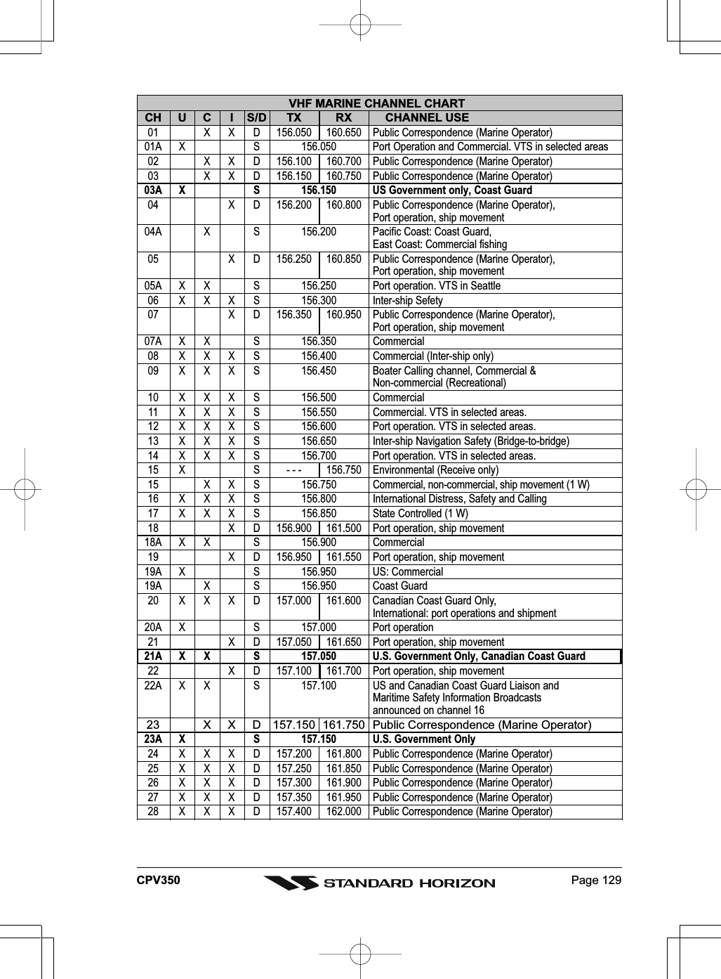
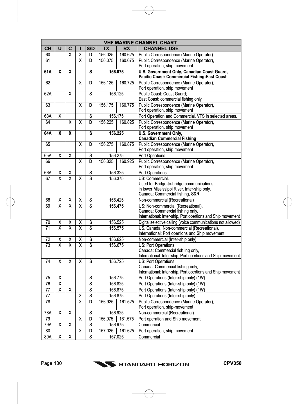
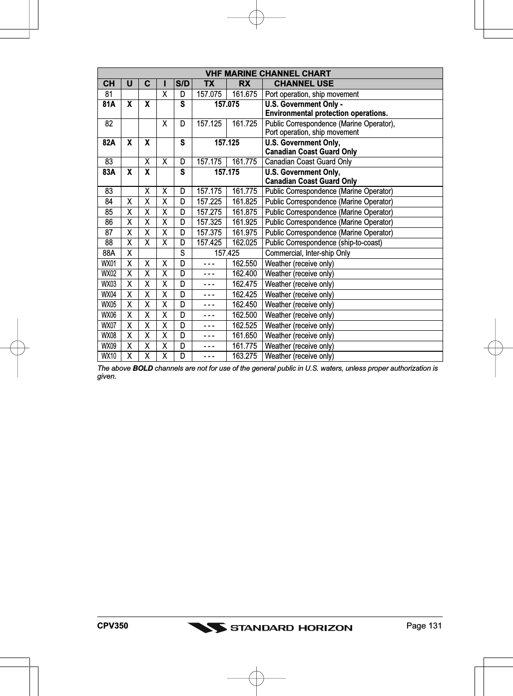
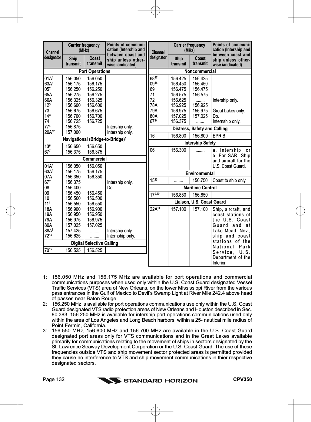
![Page 134 CPV35025. TECHNICAL TESTS25.0 SYSTEM TESTIf you have connected your GPS chartplotter according to the instructions, and chosen theproper menu selection for your device, and are still having problems with your GPSchartplotter, the extended auto-test should help determine the problem. Make sure the GPSchartplotter is turned Off. While pressing and holding any other key, turn the GPSchartplotter On. SYSTEM TEST menu will appear on the display:Figure 20.0 - System TestUse the ShuttlePoint knob to select the desired test. Choose the test, press [ENT]. To exitfrom any submenu press [CLR]. To exit from the System Test turn Off the GPS chartplotter.25.0.0 RAM Menu (reset)This test verifies the integrity of the memories and if desired during this test all the internalmemory can be erased and the default setting restored.RAM TestTo verify the integrity of the RAM. If on the screen the message ERROR appears, the RAMis physically damaged. Contact your Dealer or STANDARD HORIZON.RAM ClearTo clear internal memory. If the GPS chartplotter exhibits unusual operations, or appearsto be malfunctioning, it may be possible to correct the problem by clearing RAM.This operation will erase all Marks, Routes, stored Track plots and Destinations. It will alsoreturn all selections (Input Data Format, Autopilot selection, etc.) to original default values.To confirm clear RAM press [ENT] again (but if at this time you do not wish to clear RAMpress [CLR]).25.0.1 DIM MenuTo select the desired value for brightness and keypad light.ContrastEach time you move the ShuttlePoint knob to right, the screen will decrease brightness,move it to the left to increase brightness.BacklightThe second option allows to set the backlight. Operates in similar mode as Contrast.](https://usermanual.wiki/Yaesu-Musen/30163X3S.USERS-MANUAL-2-OF-2/User-Guide-645731-Page-93.png)
![Page 135CPV35025.0.2 CartridgesTo check the C-CARD and its connector.Background ROMTo test the WorldWideBackground. If there is not a malfunction, the code of the Backgroundand the message "OK" are shown, but if the Background is defective the message "Faulty"is shown.C-CARD TestTo test the C-CARD. There are the possible situations:1. if there is a C-CARD inserted in the slot and there is not a malfunction, the name of theC-CARD zone and the message "OK" are shown.2. if there is a C-CARD inserted in the slot, but it is a defective C-CARD, the name of theC-CARD zone and the message "Faulty" are shown.3. if there is not any C-CARD inserted in the slot, the message "not present" is shown.4. if there is a User C-CARD inserted in the slot, the message USER C-CARD is shown.C-CARD ConnectorIndicates if there is a malfunction in the connector.25.0.3 Serial PortsIf you are having problems receiving data from the position-finding instrument, this testshould help determine the problem.Change ParametersTo change the parameters of the serial interface. This menu allows to select the Port (SignalSource), the Baud Rate, the Data Bits (Word Length), the Parity, the Stop Bits.Input Data DisplayTo allow the GPS chartplotter to act as a computer terminal and display the incoming dataexactly as it is received. If the data displayed on the screen is unrecognizable, you may haveselected the wrong input parameters for your particular receiver, for example, Baud Rate9600 instead of Baud Rate 4800. Check your receiver manual to be sure that you haveselected the proper parameter. If the screen is blank, you may have a broken connection,and no data is being received or you may have connected the device to the other input port.Use [ZOOM] to stop (or continue after pause) data displaying, [ENT] to show data in hexor ASCII mode (normal or small) and [CLR] to exit.25.0.4 Modem testChecks the Modem connections (to be used only if the C-COM Modem is connected).Press [ENT] to select the desired Modem Port to the Port to which the Modem C-COM isconnected.](https://usermanual.wiki/Yaesu-Musen/30163X3S.USERS-MANUAL-2-OF-2/User-Guide-645731-Page-94.png)