Yaesu Musen 30163X3S MOBILE MARINE RADIO User Manual CPV350 Owner s Manual Chart Section V3 p65
Yaesu Musen Co., Ltd. MOBILE MARINE RADIO CPV350 Owner s Manual Chart Section V3 p65
Contents
- 1. USERS MANUAL 1 OF 2
- 2. USERS MANUAL 2 OF 2
USERS MANUAL 1 OF 2
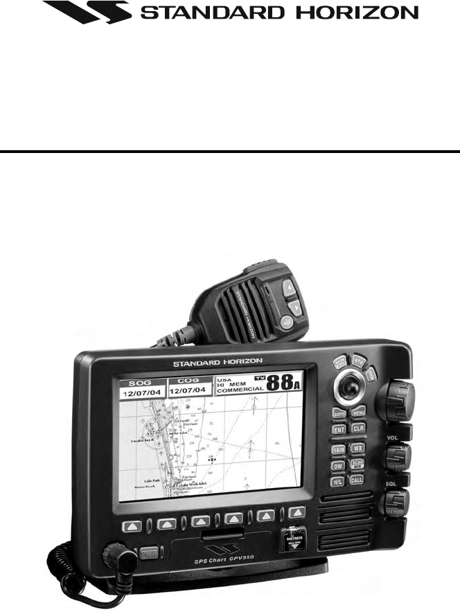
CPV350
GPS Chart Plotter
with VHF FM Marine Transceiver
OWNER'S MANUAL

Page 2 CPV350
WARNING!!!
Electronic charts displayed by the CPV350 are believed to be accurate and reliable,
but that are not intended to be a substitute for the official charts, which should remain
your main reference for all matters related to the execution of safe navigation.
For this reason we would like to remind you that you should carry on board and use
the official published and approved nautical charts.
FCC NOTICE
This equipment has been tested and found to comply with the limits for a Class A
digital device, pursuant to part 15 of the FCC Rules. These limits are designed to
provide reasonable protection against harmful interference when the equipment is
operated in a commercial environment. This equipment generates, uses, and can
radiate radio frequency energy and, if not installed and used in accordance with the
instruction manual, may cause harmful interference to radio communications.
Operation of this equipment in a residential area is likely to cause harmful
interference in which case the user will be required to correct the interference at his
own expense.
NOTICE
Unauthorized changes or modifications to this equipment may void compliance with
FCC Rules. Any change or modification must be approved in writing by Marine
Division of Vertex Standard.
Page 3CPV350
Congratulations on you purchase of the CPV350C GPS Chart Plotter with VHF FM Marine
Transceiver!
Whether this is your first GPS chartplotter, or if you have other STANDARD HORIZON
equipment, the STANDARD HORIZON organization is committed to ensuring your enjoy-
ment of this GPS chartplotter. STANDARD HORIZON technical support personnel stand
behind every product we sell, and our Product Support team invites you to contact us should
you require technical advice or assistance, at 800/767-2450.
CLEANING PROCEDURE FOR THE CHARTPLOTTER SCREEN
Cleaning of the chartplotter screen is a very important and must be done carefully.
Since the surface is covered by a antireflective coating, the procedure for cleaning
all the surfaces can be performed using the following procedure: You need a soft
tissue or towel and a cleaning spray (Windex) containing Isopropanol (a normal
spray cleaner sold for a PC screen, for example PolaClear by Polaroid). Fold the
tissue or lens tissue into a triangular shape, moisten the tip and use the index finger
behind a corner to move the tissue across the surface, in overlapping side to side
strokes. If the tissue is too wet, a noticeable wet film will be left in its path and you
will need to repeat the process. If too dry, the tissue won’t glide easily, and may
damage the surface.
CAUTION
The GPS chartplotter is designed for maritime use. Please give attention to avoid
water intrusion into the C-MAP NT+/MAX C-CARD cartridge holder.
Extensive exposure to heat may result in damage to the GPS chartplotter.
The GPS chartplotter contains dangerous high voltage circuits which only expe-
rienced technicians can handle.
STANDARD HORIZON will not be liable for errors contained herein, or for
incidental or consequential damages in connection with the performance or use
of this material.

Page 4 CPV350
TABLE OF CONTENTS
1. INTRODUCTION .......................................................................................................................... 8
1.0 GENERAL INFORMATION .............................................................................................. 8
1.1 PACKING LIST .................................................................................................................9
1.1.0 Packing List ........................................................................................................ 9
1.2 OPTIONAL ACCESSORIES ............................................................................................ 9
1.3 SAFETY / WARNING INFORMATION ........................................................................... 10
1.3.0 VHF Marine Antenna Installation ...................................................................... 10
1.3.1 ON-LINE Warranty Registaration ..................................................................... 10
1.3.2 Product Support Inquires .................................................................................. 10
1.4 FCC RADIO LICENSE INFORMATION ......................................................................... 11
1.4.0 Station License ................................................................................................. 11
1.4.1 Radio Call Sign ................................................................................................ 11
1.4.2 Canadian Ship Station Licensing ..................................................................... 11
1.4.3 FCC / Industry Canada Information ................................................................. 11
2. GETTING STARTED .................................................................................................................. 12
2.0 MOUNTING THE GPS CHARTPLOTTER ..................................................................... 12
2.1 BRACKET MOUNTING .................................................................................................. 12
2.2 FLUSH MOUNTING ....................................................................................................... 13
2.3 CONNECTIONS ............................................................................................................ 14
2.3.0 Rear Panel Connections .................................................................................. 14
2.3.1 VHF Antenna .................................................................................................... 15
2.3.2 Selecting a Marine VHF Antena ....................................................................... 15
2.3.3 Coaxial Cable ................................................................................................... 16
2.3.4 Optional Enhanced Second VHF/PA Station .................................................... 17
2.3.5 NMEA Connections .......................................................................................... 19
2.3.6 Outputting NMEA to a Personal Computer ...................................................... 19
2.3.7 Serial PC Connection ....................................................................................... 19
2.3.8 Outputting GPS Coordinates ............................................................................ 20
2.3.9 NMEA Data Page ............................................................................................. 20
2.4 GPS ANTENNA .............................................................................................................. 21
2.4.0 Mounting the GPS WAAS Smart Antenna ........................................................ 21
2.4.1 Mounting on a Pole .......................................................................................... 21
2.4.2 Flush Mounting ................................................................................................. 21
2.4.3 PA Horn Connections ....................................................................................... 22
2.5 SMART GPS CONNECTOR TABLE .............................................................................. 22
2.6 BATTERY CONNECTIONS ........................................................................................... 22
2.7 OPTIONAL BLACK BOX FISH FINDER ........................................................................ 23
2.8 OPTIONAL VHF EXTERNAL SPEAKER ....................................................................... 23
3. C-MAP MAX OVERVIEW ........................................................................................................... 24
3.0 INTRODUCTION ........................................................................................................... 24
3.1 INSERTING THE C-CARD ............................................................................................ 25
4. MAP FUNCTIONS ...................................................................................................................... 26
4.0 NEW MAX FUNCTIONS MENU .................................................................................... 26
4.0.0 Zoom Type ........................................................................................................ 26
4.0.1 Fonts & Symbols .............................................................................................. 26
4.0.2 Perspective View .............................................................................................. 27
4.0.3 Dynamic Nav-Aids ............................................................................................ 27
4.0.4 Safety Status Bar (DSI - Data Safety Indicator) ............................................... 28
4.0.5 Currents Prediction ........................................................................................... 29
5. DATA FUNCTION ....................................................................................................................... 30
5.0 PICTURES & DIAGRAMS ............................................................................................. 30
5.0.0 How to show the pictures or diagrams of a Multimedia Object ........................ 31
5.1 ENHANCED PORT INFO .............................................................................................. 31
6. CONTROLS AND INDICATORS ................................................................................................ 32
6.0 CONTROLS AND CONNECTIONS ............................................................................... 32
6.1 GETTING STARTED ...................................................................................................... 33
6.1.0 Power On, Off and ShuttlePoint knob operation .............................................. 33
6.1.1 Cursor Vs. Home Mode .................................................................................... 34
6.1.2 Cursor and Menu selection speed .................................................................... 35
6.1.3 Changing the Ships Icon .................................................................................. 35
6.1.4 Changing the backlight and contrast ................................................................ 36
6.1.5 Selecting North Up or Course Up ..................................................................... 36
6.2 ADJUSTING THE TIME ................................................................................................. 37

Page 5CPV350
6.3 SELECTING LORAN TD OR OTHER COORDINATE SYSTEM ................................... 38
6.4 CHANGING THE CHART COLOR ................................................................................ 39
6.5 SELECTING PAGES USING SOFT KEYS .................................................................... 39
6.6 CUSTOMIZING THE SOFT KEYS ................................................................................. 40
6.7 OTHER SETTINGS IN GENERAL SETUP MENU ........................................................ 40
6.8 INFORMATION PAGE .................................................................................................... 41
7. USING FIND SERVICES & MORE FUNCTION ........................................................................ 42
7.0 PORT SERVICES .......................................................................................................... 42
7.1 OTHER AVAILABLE SEARCHES .................................................................................. 42
7.2 INFO ON LAKES ............................................................................................................ 43
7.2.0 Quick Info On Lakes ......................................................................................... 43
7.2.1 Full Info On Lakes ............................................................................................ 43
8. CREATING MARKS ................................................................................................................... 45
8.0 CREATING A NEW MARK USING THE CHART PAGE ................................................ 45
8.1 EDITING a MARK .......................................................................................................... 45
8.1.0 Deleting a Mark or Waypoint ............................................................................ 46
8.1.1 Moving a Mark or Waypoint .............................................................................. 46
8.2 MARKS/WAYPOINTS LIST ........................................................................................... 47
8.3 Creating a NEW MARK with the MARKS/WAYPOINTS LIST ....................................... 47
8.4 GOTO CURSOR ............................................................................................................ 48
8.5 GOTO MARK ................................................................................................................. 49
9. MAN OVER BOARD (MOB) FUNCTION .................................................................................. 50
9.0 DELETING A MOB POINT ............................................................................................. 50
10. ROUTES ..................................................................................................................................... 51
10.0 CREATING A ROUTE USING WAYPOINTS ................................................................. 51
10.1 MAKING ADDITIONAL ROUTES ................................................................................... 52
10.2 CREATING A ROUTE USING MARKS ON THE CHART PAGE ................................... 52
10.3 INSERTING A WAYPOINT INTO A ROUTE .................................................................. 53
10.4 GOTO A ROUTE ............................................................................................................ 53
10.4.0 By select Route ................................................................................................ 53
10.4.1 By Cursor key ................................................................................................... 53
10.5 OTHER SETTINGS IN ROUTE MENU .......................................................................... 54
11. TRACKS ..................................................................................................................................... 55
11.0 TRACKING ..................................................................................................................... 55
11.0.0 Saving and starting a new Track ...................................................................... 56
11.0.1 Other Settings in Track Menu ........................................................................... 56
11.1 USING THE TRIP LOG .................................................................................................. 57
11.1.0 Resetting the Trip Log ...................................................................................... 57
12. USER C-CARD .......................................................................................................................... 58
12.0 USER C-CARD MENU .................................................................................................. 58
12.0.0 Formatting the User C-CARD .......................................................................... 58
12.0.1 Transferring files to the optional User C-CARD ............................................... 59
12.0.2 Loading a file .................................................................................................... 59
12.0.3 Deleting a file from the User C-CARD ............................................................. 59
13. PAGES ....................................................................................................................................... 60
13.0 CHART PAGE ................................................................................................................ 61
13.0.0 Window Selections ........................................................................................... 61
13.0.1 Additional Functions on Chart page ................................................................. 62
13.0.2 Turning Off Information on Icon Points ............................................................. 62
13.0.3 Display Mode .................................................................................................... 62
13.0.4 Marine Settings ................................................................................................ 63
13.0.5 Depth Settings .................................................................................................. 63
13.0.6 Land Settings ................................................................................................... 64
13.0.7 Chart Settings ................................................................................................... 64
13.0.8 Underwater Objects Settings ............................................................................ 64
13.0.9 Customizing the Data Windows ....................................................................... 65
13.1 CUSTOMIZING CHART SETTINGS .............................................................................. 65
13.2 NAVIGATION PAGE ....................................................................................................... 66
13.3 HIGHWAY PAGE ............................................................................................................ 67
13.4 CELESTIAL PAGE ......................................................................................................... 67
13.5 GPS STATUS PAGE ...................................................................................................... 68
13.6 NMEA DISPLAY PAGE ................................................................................................... 68
13.7 NMEA DATA PAGE ........................................................................................................ 69
13.8 NMEA DEPTH, WIND SPEED, TEMP AND SOG TREND PAGES ............................... 69
13.9 VHF DIGITAL SELECTIVE CALLING ............................................................................ 70
13.9.0 Position Request .............................................................................................. 70

Page 6 CPV350
14. ADVANCED SETTINGS ............................................................................................................. 71
14.0 NAVIGATE ...................................................................................................................... 71
14.1 COMPASS ...................................................................................................................... 72
14.2 INPUT/OUTPUT (NMEA) ............................................................................................... 72
14.3 ALARMS ........................................................................................................................ 72
15. AIS .............................................................................................................................................. 74
15.0 AIS SYSTEM DEFINITIONS .......................................................................................... 74
15.1 AIS MENU ...................................................................................................................... 75
15.2 TO SET THE CHARTPLOTTER FOR RECEIVING AIS ................................................ 75
15.3 QUICK INFO ON AIS TARGET ...................................................................................... 76
16. C-MAP WEATHER SERVICE .................................................................................................... 77
16.0 C-WEATHER SERVICE MENU ..................................................................................... 77
16.0.0 Download ......................................................................................................... 77
16.0.1 Copy From User C-CARD ................................................................................ 78
16.0.2 Weather Forecast ............................................................................................. 88
16.0.3 Real Time View ................................................................................................ 88
17. RADIO CONTROLS AND INDICATORS ................................................................................... 79
17.0 CONTROLS AND KEYS ................................................................................................ 79
17.1 RECEIVER AUDIO TONE CONTROL ........................................................................... 81
18. BASIC RADIO OPERATION ...................................................................................................... 82
18.0 RECEPTION .................................................................................................................. 82
18.1 TRANSMISSION ............................................................................................................ 82
18.2 TRANSMIT TIME-OUT TIMER (TOT) ............................................................................ 82
18.3 SIMPLEX/DUPLEX CHANNEL USE .............................................................................. 82
18.4 INTERNATIONAL, USA, AND CANADA MODE ............................................................ 83
18.5 NOAA WEATHER CHANNELS ...................................................................................... 83
18.5.1 NOAA Weather Alert ........................................................................................ 83
18.5.2 NOAA Weather Alert Test ................................................................................. 84
18.5.3 Customizing NOAA Weather Alert ................................................................... 84
18.6 EMERGENCY CHANNEL (CHANNEL 16 USE) ............................................................ 84
18.7 CALLING ANOTHER VESSEL (CHANNEL 16 OR 9) ................................................... 85
18.8 MAKING TELEPHONE CALLS ...................................................................................... 85
18.9 OPERATING ON CHANNELS 13 AND 67 ..................................................................... 86
18.10 DUAL WATCH (TO PRIORITY CHANNEL) ................................................................... 86
18.11 SCANNING .................................................................................................................... 86
18.11.0 Selecting the Scan Type ................................................................................... 86
18.11.1 Memory Scanning (M-SCAN) ........................................................................... 87
18.11.2 Priority Scanning (P-SCAN) ............................................................................. 87
18.11.3 Priority Channel Set ......................................................................................... 88
18.12 PA/FOG OPERATION .................................................................................................... 89
18.12.0 Operating the PA HAIL mode ........................................................................... 89
18.12.1 Operating the FOG HORN mode ..................................................................... 89
18.12.2 FOG ALERT TONE Frequency ........................................................................ 91
18.13 INTERCOM OPERATION .............................................................................................. 91
18.14 VOICE SCRAMBLER ..................................................................................................... 92
18.14.0 Setting Up the Voice Scrambler ....................................................................... 92
18.14.1 Voice Scramble Operation ............................................................................... 93
19 DIGITAL SELECTIVE CALLING ................................................................................................ 94
19.0 GENERAL ...................................................................................................................... 94
19.1 MARITIME MOBILE SERVICE IDENTITY (MMSI) ........................................................ 94
19.1.0 What is an MMSI? ............................................................................................ 94
19.1.1 Programming the MMSI ................................................................................... 95
19.2 DSC Distress Call .......................................................................................................... 95
19.2.0 Transmitting a DSC Distress Call ..................................................................... 95
19.2.1 Receiving a DSC Distress Call ........................................................................ 97
19.3 ALL SHIPS CALL ........................................................................................................... 97
19.3.0 Transmitting an All Ships Call ........................................................................... 97
19.3.1 Receiving an All Ships Call .............................................................................. 98
19.4 INDIVIDUAL CALL ......................................................................................................... 98
19.4.0 Setting up the Individual / Position Call Directory ............................................ 98
19.4.1 Setting up Individual Reply ............................................................................... 99
19.4.2 Setting up the Individual/Group Call Ringer ................................................... 100
19.4.3 Transmitting an Individual Call ....................................................................... 101
19.4.4 Receiving an Individual Call ........................................................................... 102
19.5 CALL WAITING DIRECTORY ...................................................................................... 103

Page 7CPV350
19.5.0 Enabling the Call Waiting Feature .................................................................. 103
19.5.1 Reviewing Received Calls Logged into the Call Waiting Directory ................ 103
19.5.2 To Delete the Received Log from the “DSC Log" Directory ........................... 104
19.6 GROUP CALL .................................................................................................................. 105
19.6.0 Setting up a Group Call .................................................................................. 105
19.6.1 Transmitting a Group Call .............................................................................. 106
19.6.2 Receiving a Group Call .................................................................................. 107
19.7 POSITION REQUEST .................................................................................................. 107
19.7.0 Setting up Position Reply ............................................................................... 107
19.7.1 Transmitting a Position Request to Another Vessel ....................................... 108
19.7.2 Receiving a Position Request ........................................................................ 110
19.8 POSITION SEND ......................................................................................................... 110
19.8.0 Setting up a Position Send Ringer ................................................................. 110
19.8.1 Transmitting a DSC Position Send Call ......................................................... 111
19.8.2 Receiving a DSC Position Send Call ............................................................. 112
20. RADIO SETUP ......................................................................................................................... 113
20.0 CHANNEL NAME CHANGE ........................................................................................ 113
20.1 UNIT NAME ................................................................................................................. 114
21. ENHANCED RAM+ MIC OPERATION .................................................................................... 115
21.0 RAM+ MIC CONTROLS .................................................................................................. 115
21.1 PA/FOG OPERATION ................................................................................................. 116
21.1.0 Operating the PA / Hailer .................................................................................. 116
21.1.1 Operating the FOG Horn .................................................................................. 117
21.2 INTERCOM OPERATION ............................................................................................ 117
21.2.0 Communication ................................................................................................ 117
21.2.1 Calling .............................................................................................................. 117
21.3 DSC/RADIO SETUP MODE ........................................................................................ 118
22. VH-310 HANDSET OPERATION .............................................................................................. 119
22.0 VH-310 HANDSET CONTROLS .................................................................................. 119
22.1 PA/FOG OPERATION .................................................................................................. 122
22.1.0 Operating the PA / Hailer .................................................................................. 122
22.1.1 Operating the FOG Horn .................................................................................. 122
22.2 INTERCOM OPERATION ............................................................................................ 111
22.2.0 Communication ................................................................................................ 122
22.2.1 Calling .............................................................................................................. 123
22.3 MANUAL INPUTTING OF THE GPS LOCATION (LAT/LON) ..................................... 123
22.4 DSC/RADIO SETUP MODE ........................................................................................ 124
22.4.1 Changing GPS Information to Vessel position or COG .................................... 125
22.4.2 External Speaker AF Selection ........................................................................ 125
23. MAINTENANCE ....................................................................................................................... 126
23.0 REPLACEMENT PARTS .............................................................................................. 126
23.1 FACTORY SERVICE .................................................................................................... 127
23.2 TROUBLESHOOTING ................................................................................................. 127
24. CHANNEL ASSIGNMENTS ..................................................................................................... 128
25. TECHNICAL TESTS ................................................................................................................ 134
25.0 SYSTEM TEST ............................................................................................................ 134
25.0.0 RAM Menu (reset) .......................................................................................... 134
25.0.1 DIM Menu ....................................................................................................... 134
25.0.2 Cartridges ....................................................................................................... 135
25.0.3 Serial Ports ..................................................................................................... 135
25.0.4 Modem test ..................................................................................................... 135
26. WARRANTY ............................................................................................................................. 136
26.0 MARINE PRODUCTS LIMITED WARRANTY ............................................................. 136
26.1 ON-LINE WARRANTY REGISTRATION ..................................................................... 138
27. SPECIFICATIONS .................................................................................................................... 140
27.0 CPV350 SPECIFICATIONS ......................................................................................... 140
27.0.0 GENERAL ...................................................................................................... 140
27.0.1 TRANSMITTER .............................................................................................. 140
27.0.2 RECEIVER ..................................................................................................... 140
27.0.3 GPS CHART PLOTTER ................................................................................. 140
27.1 GPS WAAS SMERT RECEIVER SPECIFICATIONS .................................................. 141
27.1.0 PHYSICAL CHARACTERSTICS .................................................................... 141
27.1.1 ELECTRICAL CHARACTERSTICS ............................................................... 141
27.1.2 GPS PERFORMANCE ................................................................................... 141
28 APENDIX: TERMS ................................................................................................................... 142

Page 8 CPV350
1. INTRODUCTION
1.0 GENERAL INFORMATION
The CPV350 is a WAAS GPS chart plotter, Class D DSC 25 W VHF with a powerful 30 W
loud hailer capable of listen-back, fog signaling, bells, whistles integrated one box. The
CPV350 has 2 connections for CMP25 RAM+ or VH-310 telephone style handset second
stations. Connect the optional FF520, and the CPV350 becomes a full function 50/200 kHz
fish finder shown on the high-resolution sunlight viewable 16:9 aspect ratio Wide Screen
display in a full page or a split Chart/fish screen. Rotary knobs make features easy to access
along with the unique ergonomically designed handgrip for sure control. Featuring Class D
Additional features include, dual watch, programmable scan, priority scan dedicated 16/9
and WX key, noise-canceling microphone with channel selection, back lit front panel keys
and LCD and a optional voice scrambler.
GPS chart plotter features include:
7-inch 256-Color TFT sunlight viewable LCD display (Screen Resolution: 800x480)
12 Channel GPS WAAS smart antenna
Cartography: C-Map NT+, C-Map MAX capable
Customizable display windows
Dual frequency fish finder capable (FF520 required)
Split screen capability
Worldwide background map showing detail up to 2.0 NM included
Stores 1000 user waypoints
NMEA data pages
Marine VHF features include:
Commercial grade ITU Class D VHF transceiver
Complete Digital Selective Calling (DSC).
Full position request and send functions
CLEAR VOICE noise reduction microphone with 16/9 key and channel selection
Tri-station capability (RAM+ and/or VH-310 required)
30W loud hailer with listen back, 4 foghorns, bells, and whistles
Oversized rotary channel selector
Channel name capability
Display repeats GPS information (when attached to GPS)
User Programmable Scan, Priority Scan, and Dual Watch
Fully adjustable backlighting and LCD contrast
Voice scrambler (optional)

Page 9CPV350
1.1 PACKING LIST
When the package containing the GPS chartplotter is first opened, please check for the
following contents.
If any parts are missing contact the dealer this GPS chartplotter was purchased from.
Accessories and replacement parts may be ordered from STANDARD HORIZON’s Parts
Department at 562/404-2700 Ext. 351 or via the web at www.standardhorizon.com.
1.1.0 Packing List
CPV350 GPS Chart Plotter with VHF FM Marine Transceiver
GPS WAAS Smart antenna
Microphone
Dust Cover
DC Power Cable
Accessory Cable
Flush Mount hardware, Mounting Bracket, and mounting hardware
Owner’s Manual
1.2 OPTIONAL ACCESSORIES
Black Box Fish Finder
FF520 - Dual Frequency Black Box Fish Finder
(500W or 1000W depending on transducer connected)
500W Transducers
DST520 - Nylon depth temp
DST521 - Transom mount depth, temp speed
DST523 - Bronze depth temp
DST525 - In-hull depth only
DST526 - Thruhull Depth, speed, temp with fairing block
1000W Transducers
DST527 - In-hull depth only
DST528 - Bronze thru-hull depth temp
Hailing horns
220SW - 5 inch round horn (small)
240SW - 5x7 horn
External Speakers
MLS-300 - VHF Extension speaker
MLS-310 - VHF Extension 10W amplified speaker
Second Station Remote Microphones
CMP25 - RAM+ Microphone
VH-310 - Telephone Style Handset
CT-100 - 23-feet Extension Cable for Second Station Remote Microphone
Scrambler
CVS2500

Page 10 CPV350
1.3 SAFETY / WARNING INFORMATION
This radio is restricted to occupational use, work related operations only where the radio
operator must have the knowledge to control the exposure conditions of its passengers and
bystanders by maintaining the minimum separation distance of 0.6 m (2 feet). Failure to
observe these restrictions will result in exceeding the FCC RF exposure limits.
1.3.0 VHF Marine Antenna Installation
The antenna must be located at least 0.6 m (2 feet) away from passengers in order to comply
with the FCC RF exposure requirements.
1.3.1 On-Line Wattanty Registration
Please visit www.standardhorizon.com to register the CPV350 Marine VHF. It should be
noted that visiting the Web site from time to time may be beneficial to you, as new products
are released they will appear on the Marine Division of Vertex Standard Web site.
1.3.2 Product Support Inquiries
If you have any questions or comments regarding the use of the CPV350, you can visit the
Marine Division of Vertex Standard Web site to send an E-Mail or contact the Product
Support team at 800-767-2450 M-F 7:00- 5:00PST.

Page 11CPV350
1.4 FCC RADIO LICENSE INFORMATION
Vertex Standard radios comply with the Federal Communication Commission (FCC)
requirements that regulate the Maritime Radio Service.
1.4.0 Station License
An FCC ship station license is no longer required for any vessel traveling in U.S. waters
(except Hawaii) which is under 20 meters in length. However, any vessel required carrying
a marine radio on an international voyage, carrying a HF single side band radiotelephone
or marine satellite terminal is required to have a ship station license. FCC license forms,
including applications for ship (506) and land station licenses can be downloaded via the
Internet at www.fcc.gov/forms. To obtain a form from the FCC, call (888) 225-5322.
1.4.1 Radio Call Sign
Currently the FCC does not require recreational boaters to have a Ship Radio Station
License. The USCG recommends the boats registration number and the state to be used.
1.4.2 Canadian Ship Station Licensing
You may need a license when traveling in Canada. If you do need a license contact the
nearest field office or regional office or write:
Industry Canada
Radio Regulatory Branch
Attn: DOSP
300 Slater Street
Ottawa, Ontario
Canada, KIA 0C8
1.4.3 FCC / Industry Canada Information
The following data pertaining to the transceiver is necessary to fill out the license
application.
Type Acceptance ........................................................................................... FCC Part 80
Output Power ................................................................. 1 Watt (low) and 25 Watts (high)
Emission ........................................................................................... 16K0G3E, 16K0G2B
Frequency Range ....................................................................... 156.025 to 163.275 MHz
FCC Type Number ...................................................................................... K6630163X3S
Industry Canada Type Approval .............................................................. 511B-30163X3S
Page 12 CPV350
2. GETTING STARTED
2.0 MOUNTING THE GPS CHARTPLOTTER
The CPV350 is supplied with hardware for bracket or flush mounting. Below are pictures
showing actual examples of the two types of installation.
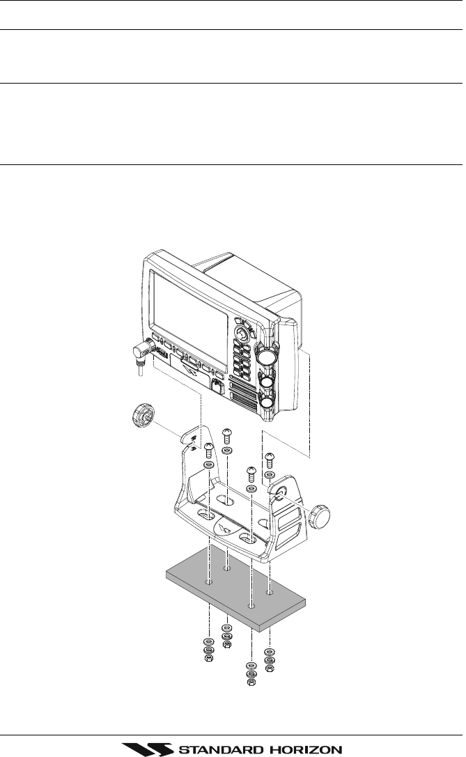
2.1 BRACKET MOUNTING
The CPV350 can be mounted using the supplied bracket. Before installing ensure the area
the CPV350’s bracket is mounted to is strong enough to support the weight of the CPV350
especially while under way.
After the location is found, attach the mounting base to the area using the supplied hardware.
Figure 2.1 - Installing CPV350 (Bracket)
Page 13CPV350
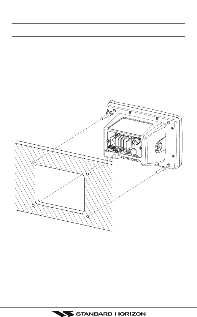
2.2 FLUSH MOUNTING
The CPV350 is supplied with a flush mount template for the cutout hole and screw holes
required to install the CPV350.
NOTE
Before drilling holes ensure there are no obstructions behind the location that could interfere with
the mounting and there is physically enough room to mount the CPV350.
1. After a location is found, peal the template label from the backing and apply the label
to the mounting area.
2. Drill a hole in one area of the cut area that will allow the blade of a jig saw to be inserted.
Insert and cut out the area on the panel using the jig saw.
3. Remove the three screws affiex the grip and remove the grip from the CPV350.
4. Next drill the four holes required to insert the CPV350 with the mounting studs.
5. Install the mounting studs on the CPV350 and insert into the mounting hole.
6. Attach the CPV350 to the mounting location by attaching the supplied hardware to the
mounting studs.
Figure 2.2 - Installing CPV350 (Flush)
Page 14 CPV350
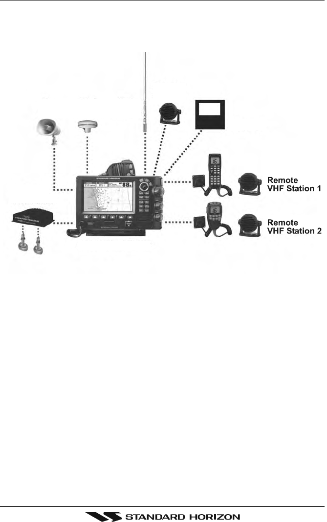
PA
Horn
GPS
Antenna
VHF
Antenna
External
Speaker
Autopilot
CPV350
FF520
Fish Finder
Figure 2.4 Installing the GPS WAAS Smart antenna
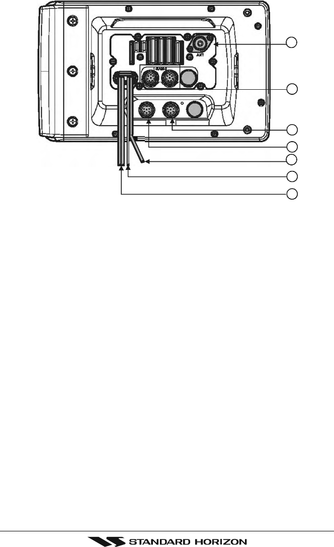
2.3.0 Rear Panel Connections
1. VHF ANTENNA JACK
Connects an antenna to the transceiver. Use a marine VHF antenna with impedance
of 50 ohms.
2. REMOTE MIC CONNECTORS
Connects to the enhanced RAM+ MIC (Remote Access Microphone) or the VH-310
Handset.
3. ACCESSORY CONNECTION
Allows connection of optional FF520 fish finder module and connections for AIS receiver
and other NMEA devices.
4. GPS Antenna
Connects the GPS antenna to the CPV350. Only use the GPS Smart antenna supplied
with the CPV350
5. External speaker
Connects to the MLS-300, MLS-310 or any 8 Ohm 6Watt external speaker
6. PA Horn
Connects to 220SW, 240SW or any 4 Ohm 30W PA Speaker
7. DC INPUT CABLE
Connects the radio to a DC power supply capable of delivering 12V DC.
2.3 CONNECTIONS
The CPV350 has a cable or connectors that are used to connect the CPV350 to Power
Supply, to the GPS WAAS Smart antenna, optional FF520 50/200kHz BLACK BOX FISH
FINDER and to NMEA devices such as VHF's, digital instruments and autopilots as shown
in the image below:
Page 15CPV350
Figure 2.5 CPV350 Rear Panel
2.3.1 VHF Antenna
ABOUT VHF RADIO
The radio frequencies used in the VHF marine band lie between 156 and 158 MHz with some
shore stations available between 161 and 163 MHz. The marine VHF band provides
communications over distances that are essentially “line of sight” (VHF signals do not travel
well through objects such as buildings, hills or trees). Actual transmission range depends
much more on antenna type, gain and height than on the power output of the transmitter.
On a fixed mount 25W radio transmission expected distances could be greater than 15
miles.
2.3.2 Selecting a Marine VHF Antenna
Marine antennas are made to radiate signals equally in all horizontal directions, but not
straight up. The objective of a marine antenna is to enhance the signal toward the horizon.
The degree to which this is accomplished is called the antenna’s gain. It is measured in
decibels (dB) and is one of the major factors in choosing an antenna. In terms of effective
radiated power (ERP), antennas are rated on the basis of how much gain they have over
a theoretical antenna with zero gain. A 3-foot, 3dB gain antenna represents twice as much
gain over the imaginary antenna. Typically a 3-foot 3dB gain stainless steel whip is used on
a sailboat mast. The longer 8-foot 6dB fiberglass whip is primarily used on powerboats that
require the additional gain.
1
5
2
3
4
6
7
Page 16 CPV350
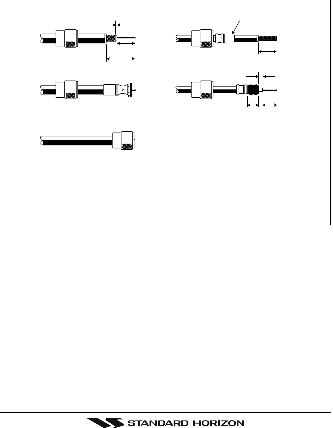
1/16''
3/4''
3/4''
1 1/8''
1/8''
5/8''3/8''
Adapter
2.3.3 Coaxial Cable
VHF antennas are connected to the transceiver by means of a coaxial cable - a shielded
transmission line. Coaxial cable is specified by its diameter and construction. For runs less
than 20 feet, RG-58/U, about 1/4 inch in diameter is a good choice. For runs over 20 feet
but less than 50 feet, the larger RG-8X should be used for cable runs over 50 feet RG213
should be used. For installation of the connector onto the coaxial cable refer to the figure
below. Figure 2.4.0 Installing the VHF antenna To get your coax cable through a fitting and
into your boat's interior, you may have to cut off the end plug and reattach it later. You can
do this if you follow the directions that come with the connector. Be sure to make good
soldered connections.
Figure 2.4.0 Installing the VHF antenna
To get your coax cable through a fitting and into your boat’s interior, you may have
to cut off the end plug and reattach it later. You can do this if you follow the
directions that come with the connector. Be sure to make good soldered
connections.
Page 17CPV350
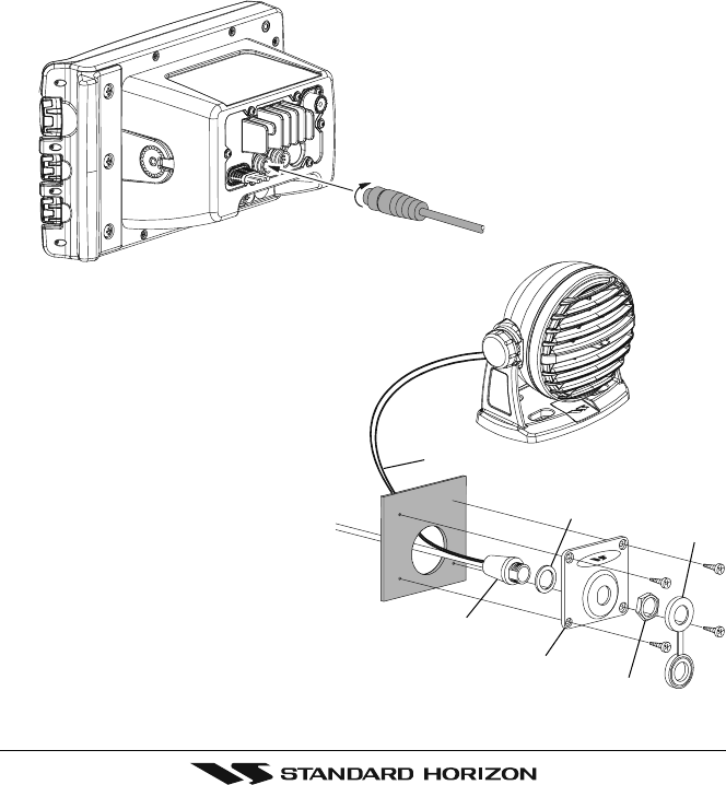
2.3.4 Optional Enhanced Second VHF/PA Station
INSTALLATION
The CPV350 is capable of using up to 2 Enhanced RAM+ mics or VH-310 Handset to
remotely control the Radio, DSC, and Distress functions. In addition the CPV350 can
operate as a full function intercom system.
1. Connect the Routing Cable to the one of the Remote Mic eight pin connector on the rear
panel, then tighten the Cable Nut.
2. Referring to Figure 3, make a 1.2” (30 mm) hole in the wall, then insert the Routing Cable
into this hole. Connect the Gasket and Mount Base to the Routing Cable Connector
using the Nut.
3. Drill the four Screw holes (approx. 2 mm) on the wall then install the Mounting Base to
the wall using four screws.
4. Put the Rubber Cap on to the Nut. The installation is now complete.
5. Wires for an external speaker are provided on the Routing Cable. Connect any 8 Ohm
external speaker. When connected the RAM+ (or VH-310 Handset) controls the volume
level of this speaker.
Wall
Gasket
Mounting Bracket
Routing Cable
Cap
Nut
External Speaker Connections
Page 18 CPV350
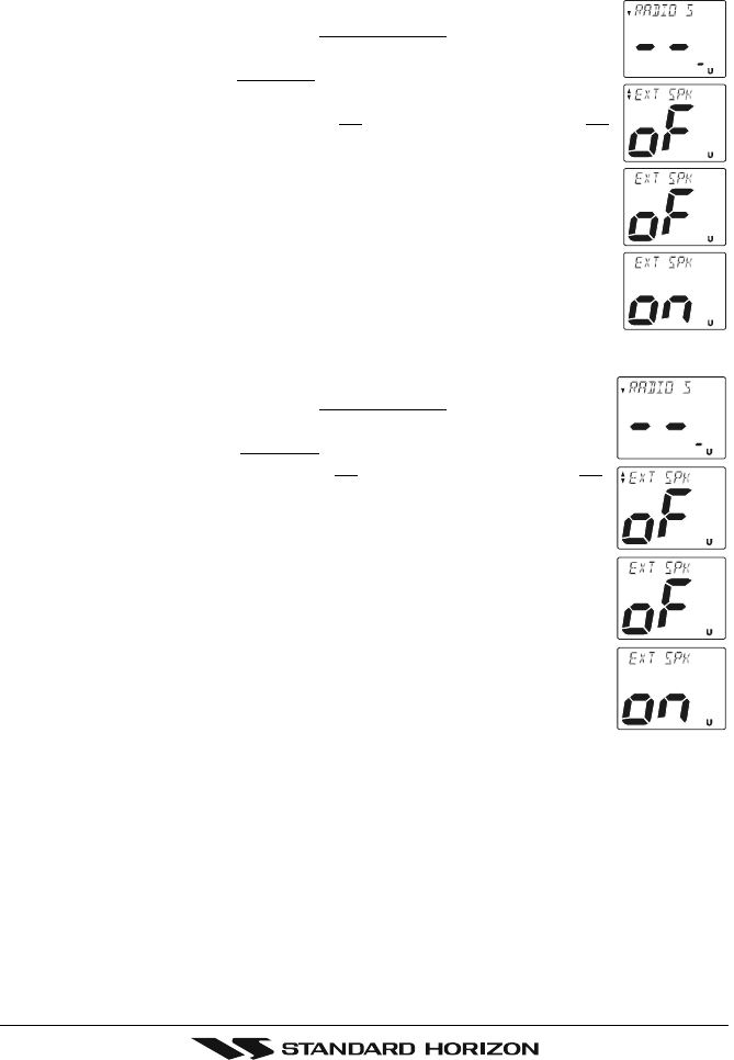
Remote Mic or External Speaker Selection
By default the RAM+ or VH-310 Handset internal speaker is turned on, however using the
RAM+ mic (or VH-310 Handset) this speaker can be turned off so the external speaker can
be used.
RAM+ mic procedure
1. Press and hold the [CALL/SET] key.
2. Press the [] or [] key to select RADIO SETUP.
3. Press the [CALL/SET] key.
4. Press the [] key to until EXT SPK is shown and press the [CALL/SET]
key.
5. Press the [] or [] key to select oF (External speaker off) or on
(External speaker on).
6. Press the [CALL/SET] key to save the selection.
7. Press the [16/9] key to exit this mode.
VH-310 Procedure
1. Press and hold the [CALL(MENU)] key.
2. Press the [] or [] key to select RADIO SETUP.
3. Press the [ENT] key
4. Press the [] key to until EXT SPK is shown and press the [ENT] key.
5. Press the [] or [] key to select oF (External speaker off) or on
(External speaker on).
6. Press the [ENT] key to save the selection.
7. Press the [16/9] key to exit this mode.
Page 19CPV350
2.3.5 NMEA Connections
NOTE
The CPV350 can send many sentences to external NMEA devices. The NMEA output wires are
Brown and White and the NMEA Common is Green. If you have connected devices as shown in
the below table and need to feed NMEA to other devices (Autopilot, Radar ....) you can parallel wires
from the Brown or White wires.
Pin Wire Color Description Connection Example Additional Information
1 Black -- - No Connection
2 Red -- - No Connection
3 Green NMEA Common Common for NMEA devices
4 Blue NMEA Input Port 1 Conncect to output of NMEA device Default is NMEA0183
5 Brown NMEA Output Port 1 Conncect to intput of NMEA device Default is NMEA0183 with GLL. RMB, RMC, and XTE sentences
6 Gray NMEA Input Port 2 Conncect to output of NMEA device Default is NMEA0183
7 White NMEA Output Port 2 Conncect to intput of NMEA device Default is NMEA0183 with GLL. RMB, RMC, and XTE sentences
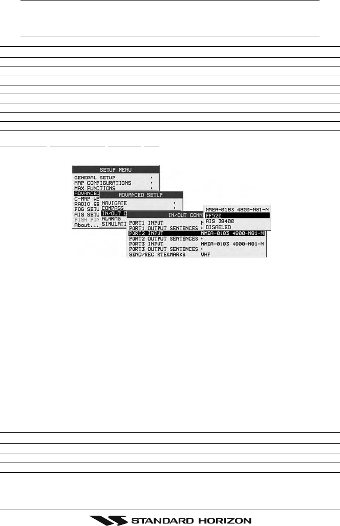
8 Yellow NMEA Output Port 4 Connect autopilot Default is NMEA0183 with APA. APB, XTE, COG, and BOD sentences
: When the FF520 is connected, port 2 input must be changed to “FF520.” To do this, press [MENU] two times, move the ShuttlePoint konb to highlight
ADVANCED SETUP, IN/OUT CONNECTIONS, PORT2 INPUT, FF520.
Figure 2.3.5 IN/OUT CONNECTION menu
2.3.6 Outputting NMEA to a Personal Computer
The CPV350 can be connected to output Marks, Routes, and tracks to many PC programs
available in the aftermarket. To send or receive User Points the PC Program must be able
to receive NMEA WPL and RTE sentences.
2.3.7 Serial PC Connection
Outputting Waypoints and Routes
The CPV350 can be connected to output Marks, Routes and tracks to many PC programs
available in the aftermarket. To send or receive User Points the PC Program must be able
to receive NMEA WPL and RTE sentences.
PC DB9 Connection CPV350 Connection
Pin 2 Brown wire
Pin 3 Blue
Pin 4 Green
Page 20 CPV350
2.3.8 Outputting GPS Coordinates
Some PC programs use NMEA sentences from a GPS to show position. The CPV350
outputs GLL, RMB and RMC.
PC DB9 Connection CPV350 Connection
Pin 2 Brown wire
Pin 4 Green
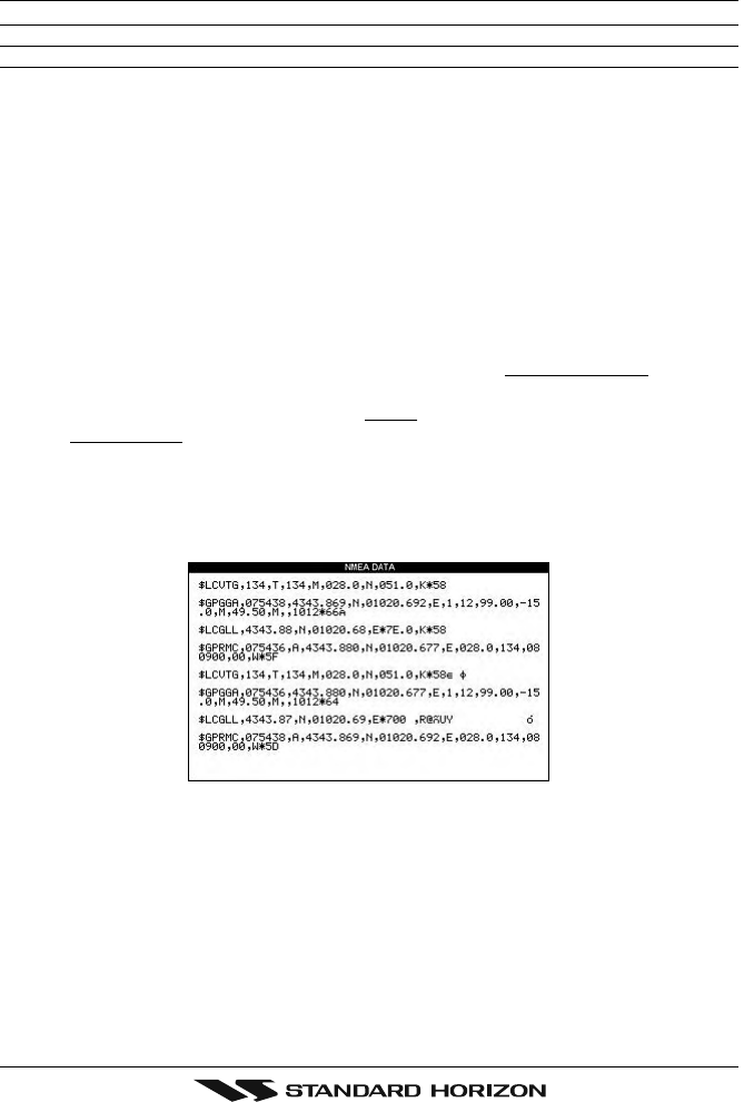
2.3.9 NMEA Data Page
The NMEA Data Page is very useful to see if an External device (example: Depth Sounder)
is transmitting NMEA sentences to the GPS chart plotter. This page can also be used to see
if the GPS chart plotter NMEA output is being loaded down by an external NMEA device
Example:
Autopilot connected but the CPV350 but is not receiving NMEA data.
Usually the Autopilot will be connected to the yellow wire.
To check to see if the GPS chart plotter is transmitting the Autopilot sentences:
1. Press [MENU]. Move the ShuttlePoint knob to highlight NMEA DISPLAY and press
[ENT].
2. Move the ShuttlePoint knob to highlight DATA and press [ENT].
3. The NMEA DATA page is shown.
4. Connect the Blue Wire on the GPS chartplotter to the junction of the yellow wire and the
autopilot. The display should look similar to the picture below.
5. If no data is shown press the [ZOOM] and move the knob on right side up to change
port.

Page 21CPV350
2.4 GPS ANTENNA
2.4.0 Mounting the GPS WAAS Smart Antenna
The CPV350 is supplied with a 12 Channel GPS WAAS Smart antenna. This antenna is
designed to be mounted on a base, installed on an extension or even flush mounted.
Choose a location for the antenna that has a clear view of the sky and is not located within
3 FT of Radar or other transmitting antenna. Ensure there are no major obstructions or
fixtures in the immediate proximity to the antenna. The antenna relies on direct “line of sight”
satellite reception. If you are unsure of the chosen location, temporarily mount the antenna
in the desired location to verify correct operation. If mounted close to Radar, and after the
GPS chartplotter has a fix, turn on the Caps on RADAR to ensure the GPS chartplotter holds
the fix (use the GPS Status Page).
2.4.1 Mounting on a Pole
The thread used on the antenna is an industry standard (1 inch 14TPI) used on a wide range
of mounting brackets. Due to the manufacturing process of these mounting brackets you
may see some slop when tightening down the antenna to the bracket. This is no concern
however as the antenna must be tightened until the antenna stops rotating.
NOTE
The antenna cable can be cut and spliced to ease installation. Care must be taken when
reconnecting the antenna cable to protect from water and corrosion.
2.4.2 Flush Mounting
NOTE
Before drilling holes, it is recommended the antenna be positioned where the location is planned
to be drilled, cable connected to the CPV350 and the CPV350 turned on to ensure a GPS fix is
received.
1. Remove the threaded base from the antenna dome.
2. To ease installation a flush mounting template for the antenna has been included.
3. Apply the mounting template sticker to the area that was verified for GPS reception.
4. Then, drill out the 0.63” (16 mm) and 0.16” (4 mm) holes, and remove the template.
5. Insert the cable into the 0.63” (16 mm) hole and route to the CPV350.
6. Apply a small amount or RTV to the under side of the antenna.
7. Place the antenna and then screw it into place using the screws. In some cases the
screw may not be long enough, if this happens simply apply more RTV to the underside
of the antenna to glue it into place.
GPS OVERALL SHAPE
CUTTING TEMPLATE
CUTTING TEMPLATE
4 mm [0.155"]
4 mm [0.155"]
0
016 mm [0.63"] or greater
0
04 mm [0.155"]
Figure 2.4.2 Installing the GPS WAAS Smart antenna

Page 22 CPV350
2.4.3 PA Horn Connections
The CPV350 can be connected to the 220SW or 240SW PA horn to hail other vessels or
send FOG, bells or whistles.
2.5 SMART GPS CONNECTOR TABLE
Pin Wire Color Description Connection Example
1 Red Battery Positive Connect to Battery Positive and Red wire of GPS Antenna
2 Green Smart GPS NMEA Input Connect to Smart GPS Input
3 Brown Smart GPS NMEA Output Connect to Smart GPS Output
4 NC --- ---
5 NC --- ---
6 Black/Yellow Battery Ground Connect to battery ground and Black wire of GPS Antenna
2.6 BATTERY CONNECTIONS
CAUTION
Reverse polarity connections will damage the radio!
1. Connect the red power wire to a 13.8 VDC ±20% power source. Connect the black
power wire to a negative ground.
2. If an optional remote extension speaker is to be used, refer to next section for
connections.
3. It is advisable to have a Certified Marine Technician check the power output and the
standing wave ratio of the antenna after installation.
Page 23CPV350
External Speaker
EXTERNAL
NMEA DEVICE
PA Speak er
Green
Blue NMEA OUT
NMEA OUT
NMEA IN
( )
( )
( )
Gray
Shield
Shield
Red
White
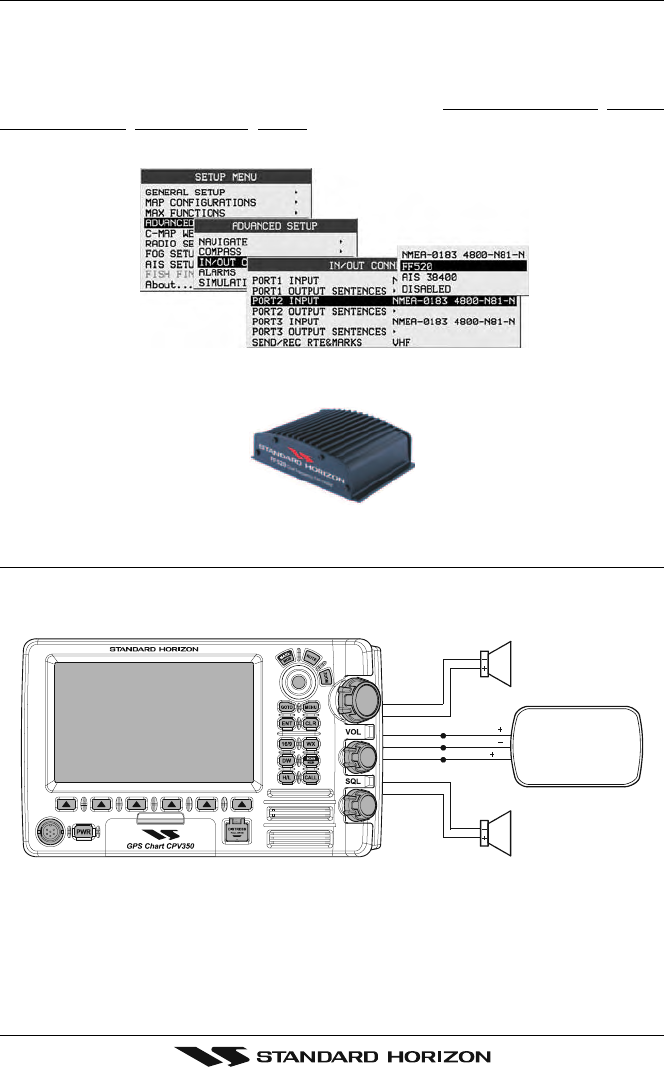
2.7 OPTIONAL BLACK BOX FISH FINDER
STANDARD HORIZON offers an optional BLACK BOX FISH FINDER called FF520. Please
refer to the Owner’s Manual supplied with the Fish Finder for connections and operation.
When the FF520 is connected, port 2 input must be changed to “FF520.” To do this, press
[MENU] two times, move the ShuttlePoint konb to highlight ADVANCED SETUP, IN/OUT
CONNECTIONS, PORT2 INPUT, FF520.
Figure 2.7 IN/OUT CONNECTION menu
2.8 OPTIONAL VHF EXTERNAL SPEAKER
THE CPV350 has connections for an external VHF speaker for louder audio. Use Standard
Horizon MLS-300 or MLS-310 for best performance.
Page 24 CPV350
3. C-MAP MAX OVERVIEW
3.0 INTRODUCTION
C-MAP MAX is a major evolution of the NT/NT+ product technology. Key points are:
New Data Features
·Tides and Currents (intuitive arrows show direction and strength)
·World Background Charts with terrestrial data
·Value Added Data (Pictures and Diagrams, Land Data)
·Enhanced Port Info
New Presentation Features
·Clear Info (sophisticated “Human Dictionary” to translate Nav-Aid abbreviations found
on paper charts)
·Dynamic Nav-Aids (an innovative and dynamic presentation mode)
·Flexi-Zoom (increased Under and Over Zoom between chart levels, resulting in optimal
scale display for any situation)
·Dynamic Elevation Data (optimized palettes for GPS chartplotters; includes new
NOAA palette)
·Perspective View (“Real World” perspective view of the chart, updated real-time during
navigation)
MAX and NT/NT+ C-CARD coexistence
·When NT+ data and MAX data cover different areas, the GPS chartplotter gets data
from both charts (depending on the current position).
·When NT+ data and MAX data cover the same area, the GPS chartplotter gets data only
from MAX chart.
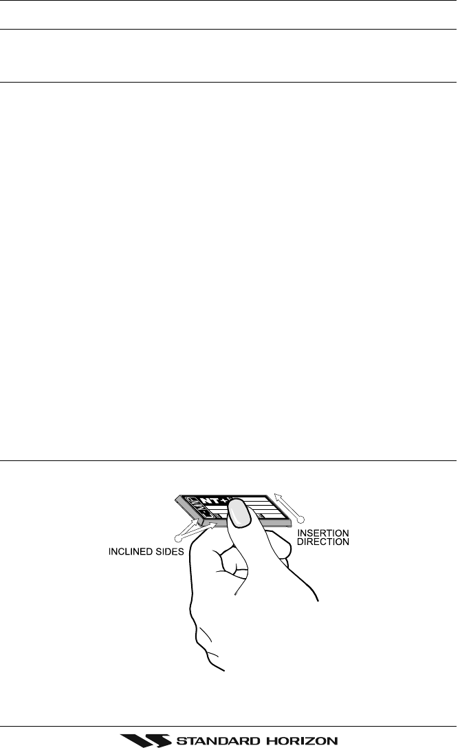
3.1 INSERTING THE C-CARD
Hold the C-CARD by the long inclined side so that you can see the C-MAP label.
Figure 3.1 - Inserting C-CARD
Page 25CPV350
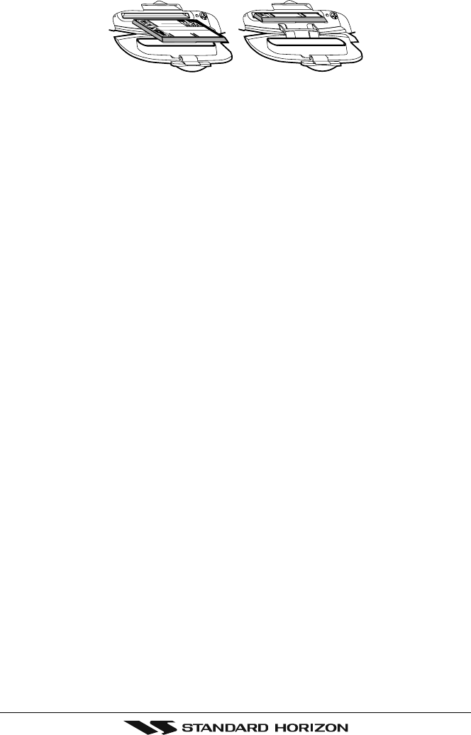
Open the door, gently push the C-CARD into the slot: push the C-CARD in as far as it will
go, then close the door.
Figure 3.1a - Inserting C-CARD (Details)
Page 26 CPV350
4. MAP FUNCTIONS
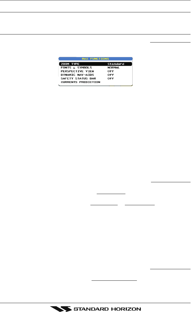
4.0 NEW MAX FUNCTIONS MENU
1. Press [MENU] two times. Move the ShuttlePoint knob to highlight MAX FUNCTIONS
and press [ENT] or move the ShuttlePoint knob to the right. The MAX Functions menu
appears on the screen:
Figure 4.0 - Map Functions Menu
The available Functions are described in the following.
4.0.0 Zoom Type
Allows more expansions or compression of the chart scale while zooming in or out. Zoom
Mode has two options; STANDARD (default) or FLEXI-ZOOM. When in FLEXI-ZOOM
mode, a short zoom push causes a change of chart, while a long zoom push causes a pop-
up window to be displayed on a corner of the screen. The window shows the current Zoom
factor. By pressing [ZOOM] and moving the knob up/down the map is expanded or
compressed according to the zoom factor selected. The window is automatically closed if
[ZOOM] is not pressed for 2 seconds and the selected zoom factor will be used at the next
zoom in/out.
To activate this function follow the procedure:
1. Press [MENU] for two times. Move the ShuttlePoint knob to highlight MAX FUNCTIONS
and press [ENT] or move the ShuttlePoint knob to the right.
2. Move the ShuttlePoint knob to highlight ZOOM TYPE and press [ENT] or move the
ShuttlePoint knob to the right.
3. The menu now shows two selections, STANDARD or FLEXI-ZOOM.
4. Move the ShuttlePoint knob to select the selection and press [ENT].
5. Press [CLR] until the menu disappears or an easier method is to move the ShuttlePoint
knob to the left a few times.
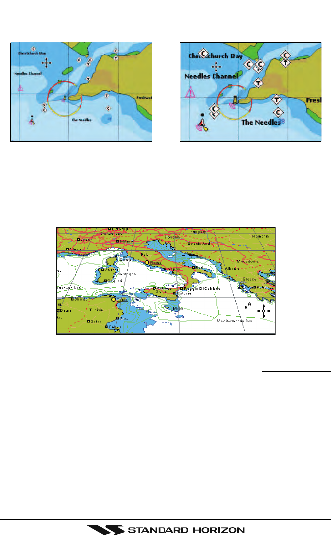
4.0.1 Fonts & Symbols
On MAX charts it is possible to set the size of all names and symbols drawn on the charts,
selecting between Normal size (the regular characters size) and Large size.
To activate this function follow the procedure:
1. Press [MENU] two times. Move the ShuttlePoint knob to highlight MAX FUNCTIONS
and press [ENT] or move the ShuttlePoint knob to the right.
2. Move the ShuttlePoint knob to highlight FONTS & SYMBOLS and press [ENT] or move
the ShuttlePoint knob to the right.
Page 27CPV350
3. The menu now shows two selections, NORMAL or LARGE.
4. Move the ShuttlePoint knob to select the selection and press [ENT].
5. Press [CLR] until the menu disappears or an easier method is to move the ShuttlePoint
knob to the left a few times.
NORMAL size LARGE size
Figure 4.0.1 - Example of Normal size (on the left side) and Large side (on the right side) settings
4.0.2 Perspective View
Chart data may be projected in perspective mode during navigation. This function allows
setting the panoramic View of the chart. As the upper side of the map is more compressed
than the lower side, a wider map area is visible. The perspective view allows showing more
chart information immediately ahead and around the cursor.
Figure 4.0.2 - Perspective View
To activate this function follow the procedure:
1. Press [MENU] for two times. Move the ShuttlePoint knob to highlight MAX FUNCTIONS

Page 28 CPV350
and press [ENT] or move the ShuttlePoint knob to the right.
2. Move the ShuttlePoint knob to highlight PERSPECTIVE VIEW and press [ENT] or move
the ShuttlePoint knob to the right.
3. The menu now shows two selections, ON or OFF.
4. Move the ShuttlePoint knob to select the selection and press [ENT].
5. Press [CLR] until the menu disappears or an easier method is to move the ShuttlePoint
knob to the left until the chart page is shown.
4.0.3 Dynamic Nav-Aids
This function enables the blinking of lights of the Nav-Aids. The blink period and color of
each Nav-Aid is read from the Nav-Aid attributes available on the data cartridge. When the
ship is inside the Nav-Aid nominal range, the light of the Nav-Aid will start blinking.
When Dynamic Nav-Aids option is set to On, when the flashing light is Off, or when fix
position is out of the sector, the light color is displayed by using a faint light color.
To activate this function follow the procedure:
1. Press [MENU] two times. Move the ShuttlePoint knob to highlight MAX FUNCTIONS
and press [ENT] or move the ShuttlePoint knob to the right.
2. Move the ShuttlePoint knob to highlight DYNAMIC NAV-AIDS and press [ENT] or move
the ShuttlePoint knob to the right.
3. The menu now shows two selections, ON or OFF.
4. Move the ShuttlePoint knob to select the selection and press [ENT].
5. Press [CLR] until the menu disappears or an easier method is to move the ShuttlePoint
knob to the left until the chart page is shown.
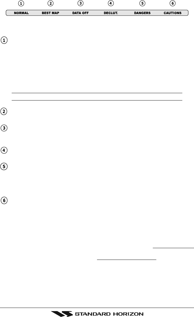
4.0.4 Safety Status Bar (DSI - Data Safety Indicator)
When Safety Status Bar is On, a status bar with six boxes showing the status of certain
functions is displayed. Any warning or alarm condition is identified by the red color to
indicate possible risk.
To activate this function follow the procedure:
1. Press [MENU] two times. Move the ShuttlePoint knob to highlight MAX FUNCTIONS
and press [ENT] or move the ShuttlePoint knob to the right.
2. Move the ShuttlePoint knob to highlight SAFETY STATUS BAR and press [ENT] or
move the ShuttlePoint knob to the right.
3. The menu now shows the following selections: ON (Safety Status Bar is shown), OFF
(Safety Status Bar is not shown), ICON (Safety Status Bar is not shown, but a Warning
alarm Icon is shown on the corner of the map screen as soon as any item controlled by
the DSI function returns an alarm condition. The Warning Icon remains displayed until
the alarm condition persists. Placing the cursor over this Icon, a quick help message is
shown next to the Icon, allowing to show the Safety Status Bar. In this case - when the
Safety Status Bar is opened via Warning alarm Icon - it is allowed to obtain information
about each “active” Safety Status box (the red ones): it is possible to select them by
ShuttlePoint knob movement left/right, and a list of active alarms is shown underneath
the selected box. By pressing [CLR], the Safety Status Bar is removed from the screen)
4. Move the ShuttlePoint knob to select the selection and press [ENT].
5. Press [CLR] until the menu disappears or an easier method is to press the ShuttlePoint
knob to the left a few times.
Page 29CPV350
Figure 4.0.4 - Safety Status Bar
The boxes are defined as follows:
Zoom
♦Normal: when the chart is displayed at normal scale.
♦U. Zoom: red when the chart is under-zoomed out more than twice normal
scale, gray otherwise.
♦O. Zoom: red when the chart is over-zoomed in more than twice normal scale,
gray otherwise.
♦Chart Lock: red when the chart is zoomed in more than twice normal scale,
gray otherwise.
NOTE
U. Zoom, O. Zoom and chart lock are used with Flexi-zoom selected.
Best Scale
Red when a more detailed chart is available under the cursor position.
Data Off
Red when at least one of the following objects or layers is turned off (by the user):
Depths/soundings; Wrecks/obstructions; Tracks/routes; Attention Areas; Nav-Aids.
Declutter
Displays red when clearing overlapping objects.
Dangers
Red when “Guardian Technology” detects one of the following objects: Land, Inter-
tidal, Depth Area, Rocks, Obstructions, Shoreline Constructions, Fishing Facility,
Wrecks, Dragged area, Diffusion area, Mooring facilities, Pingos and Production in-
stallations.
Caution
Red when “Guardian Technology” detects cautionary or restricted area.
4.0.5 Currents Prediction
When enabled shows the variation of the tidal arrows on the selected area at any given time.
To activate this function follow the procedure:
1. Press [MENU] two times. Move the ShuttlePoint knob to highlight MAX FUNCTIONS
and press [ENT] or move the ShuttlePoint knob to the right.
2. Move the ShuttlePoint knob to highlight CURRENTS PREDICTION and press [ENT]
or move the ShuttlePoint knob to the right.
3. A window is shown on the low-left side of the chart. Press [SET TIME] to set the date and
time manually, and [INCR. TIME]/[DECR. TIME] to decrease/increase time; press [EXIT] to
exit.
Page 30 CPV350
5. DATA FEATURES
This chapter contains the new features related to the MAX map data files (i.e.: cartography
and related data).
5.0 PICTURES & DIAGRAMS
Using C-Map MAX data cards allows you to show pictures or diagrams on the chart plotter
display. These Pictures are typically used to facilitate the identification of cartographic
objects or places around the map: they can be the landscape layout nearby a harbor, the
shape of a bridge or of a buoy etc.
On some objects, such as bridges, the image associated can represent the Diagram
representing the shape of the objects and the various characteristics (length, height, type
of bridge etc.).
Figure 5.0 - Pictures and Diagrams
The pictures or diagrams can be a MULTIMEDIA OBJECT or they can be associated to a
generic cartographic object, like a port marina.
Page 31CPV350
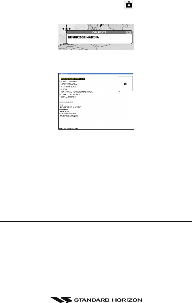
5.0.0 How to show the pictures or diagrams of a Multimedia Object
They are shown on the chart page with the camera icon
Move the cursor over the camera icon. You will get the quick info on the object and there
will be the camera icon on the top bar of the window:
Figure 5.0.0a - Example of Quick Info on MULTIMEDIA object
Press [IMAGE] for 1 second to display the image on the screen or press [EXPAND] to open
the Full info on the object:
Figure 5.0.0b - Example of Full Info on MULTIMEDIA object
On the Full Info, there will be the small camera icon on a corner of the square containing
the object icon.
To see the picture press [MENU] when the object with a picture is highlighted.
When the picture is shown, it is possible to fit it to screen by pressing [ENT].
When the picture is shown, it is possible to change the contrast by pressing [ZOOM] and
moving the knob.
When the picture is shown, it is possible to display the next picture associated, if any, by
pressing the ShuttlePoint knob left or right.
5.1 ENHANCED PORT INFO
MAX charts include additional port services that were not present before. Additional
attributes of Port Areas and Port Marinas have been included (Location, Country, Region,
State, Harbor master telephone number etc.).

Page 32 CPV350
6. CONTROLS AND INDICATORS
LEGEND
[MENU] If you see brackets around a bold and capital letter word this refers to a key press.
[CHART] If you see brackets around a bold and small capital letter word this refers to a Soft Key
press. When a word(s) is bold capital letters and underlined, this refers to a menu selection item.
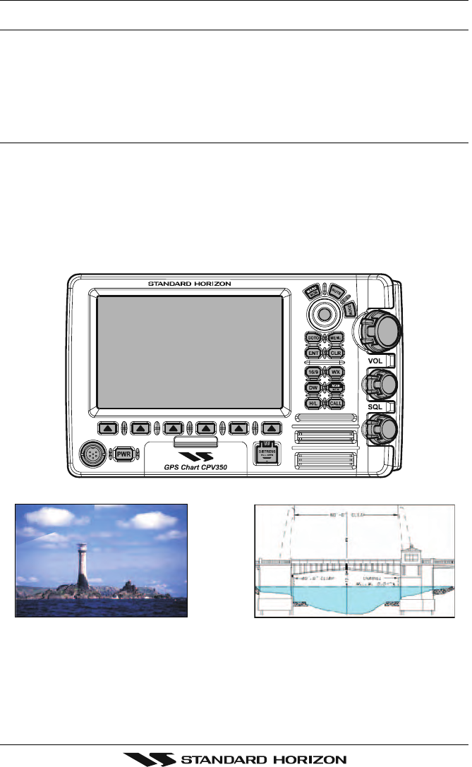
6.0 CONTROLS AND CONNECTIONS
The GPS Chart plotter, VHF radio, PA and optional FF520 fish finder are controlled using the
keys located on the front panel. These labeled keys are dedicated to specific functions. As you
press a key, a single audio beep confirms the key action; every time a key press is not valid,
three rapid beeps sound to indicate that the key action is not valid. There is also a ShuttlePoint
knob to move the cursor across the screen.
The ZOOM key
Pressing this key enables or disables the chart plotter zoom function or VHF channel
selection.
Press the [ZOOM] key and a zoom icon will appear on the top left of the display as shown
below. When this icon is shown the zoom function is enabled and the channel selector knob
is used to change the zoom levels. When the icon is not shown turning the knob changes
the VHF channels.
To zoom in rotate the channel selector knob Clockwise (up) or to zoom out rotate the
channel knob counter clockwise (down). When finished zooming press the [ZOOM] key.
Rotating the channel knob.
NOTE
The GPS chartplotter contains a Worldwide background that allows you to zoom into 2 NM. For
more detail, a C-MAP NT+/MAX C-CARD must be purchased and installed.
The ShuttlePoint knob
The ShuttlePoint knob moves the cursor about on the display screen, quickly and
accurately. It also scrolls the desired option in the menu page(s). It allows to exit from Home
mode to Cursor mode. when the setup menu is selected, moving the knob to the right selects
the desired option, as [ENT], moving it to the left exits from menu, as [CLR]. For a detailed
explanation of Cursor VS Home mode refer to section 6.1.1.
The ENT key
Press [ENT] to select the desired option or to confirm selection.
The CLR key
Press [CLR] to set Home mode. Also press [CLR] to exit from menu or data windows or to
leave a menu without making changes, to abort selected function or to step backward from
a selection made in the menu.
The MENU key
Pressing [MENU] one time selects the Main Menu. While the Main Menu is shown, move
the ShuttlePoint knob up or down or left or right to highlight a selection. Press the [ENTER]
to choose the selection.
Pressing [MENU] two times selects the Setup Menu.

Page 33CPV350
Press and hold the [MENU] key for about 3 seconds allows the fields in the data windows
to be customized on the Chart, Navigation, Highway, GPS Status or NMEA display pages.
The GOTO key
This key is very useful when you desire to start navigating (goto) to a destination point. When
pressed shows a popup window that allows you to select to start navigating to the position
of the cursor, Mark or Route.
The MARK/MOB key
Pressing [MARK/MOB] and immediately releasing places Mark under the ship's position
when in Home Mode (in Cursor Mode under the cursor).
Press and holding [MARK/MOB] for about 3 seconds automatically places a MOB on the
Chart page and all navigation is towards the position of the MOB Mark.
The RTE key
When pressed places a Waypoint. Succeeding presses place more Waypoints to form a
Route.
The PWR key and Lamp/Contrast
Press and hold [PWR] to turn the GPS chartplotter On or Off. When the CPV350 is on, press
the [PWR] key to shown the contrast and Lamp popup window. Move the ShuttlePoint knob
left/right to adjust the backlight and up/down to adjust contrast.
The Soft Keys
The 6 keys in the bottom part of the front panel (hereinafter named Soft Keys) have different
functions associated depending on the page selected: their labels are shown on the screen
immediately above the keys (the user can customize the function associated).
These keys allow quick selection to the many pages the GPS chartplotter has. These keys can
be customized to your preference, however from the factory the keys are preprogrammed with
the following pages. From left to right CHART, NAV, HIGHWAY, CELESTIAL, NMEA
DISPLAY, LIST. Press any of the keys and you will see popup windows above the keys. To
goto a specific page press the key with the desired popup window. The popup windows will
automatically disappear if a key is not pressed or can be removed by pressing [CLR].
6.1 GETTING STARTED
The Getting Started section will take you through the frequently used operations and assist
you to customize the look of the GPS chartplotter.
Legend:
[MENU] If you see brackets around a bold and capital letter word this refers to a key press.
[CHART]If you see brackets around a bold and small capital letter word this refers to a Soft Key press.
GENERAL SETUP When a word(s) is bold capital letters and underlined, this refers to a menu selection item.
6.1.0 Power On, Off and ShuttlePoint knob operation
1. Press and hold [PWR] until the display shows the start-up page. To turn off, press and
hold [PWR] until the display turns off.
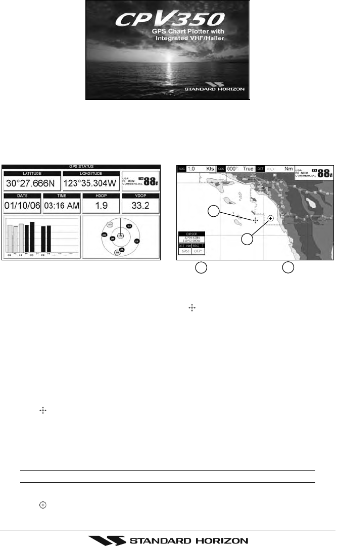
2. When the power is first turned on two pages (the start-up page, see the following picture,
and the Caution page) are briefly shown before the GPS Status page.
Page 34 CPV350
Figure 6.1.0 - Start-Up page
3. When the GPS chartplotter is first turned on it will take some time for the GPS to acquire
a fix of your position. Look closely at the GPS Status page and you will see satellites and
relative signal strengths. After a fixed is received the GPS chartplotter will automatically
switch to the Chart page with a ships icon centered on the screen.
Cursor Ships Icon
2
1
2
1
Figure 6.1.0a - GPS Status and Chart pages
4. On the Chart page the ShuttlePoint knob is used to pan around the chart. Move the ShuttlePoint
knob to the left and you will notice a cross hair appears, this is called the cursor.
5. When you move the ShuttlePoint knob you will notice DST and BRG values in the Data
window change. This shows the Distance and Bearing from the GPS Fix of your vessel
to the position of the Cursor.
6. If the cursor is moved to the edge of the screen the GPS chartplotter will automatically
pan in the desired direction.
6.1.1 Cursor Vs. Home Mode
Cursor Mode
When the cursor is shown on the Chart page, this is called Cursor mode.
In Cursor mode the position of the vessel will not stay in the center of the page and will move
right off the edge of the screen (as your boat moves) Cursor mode allows you to pan around
and look at areas on the map. In this mode your can also measure distance and bearings
from your current position.
NOTE
To change from Cursor mode to Home mode press [CLR].
Home mode
When the ships icon is only shown on the Chart page (cursor is not shown) you are in
Page 35CPV350
Home mode. Now as the ship moves through the water the vessels position will be kept in
the center of the display.
6.1.2 Cursor and Menu selection speed
The GPS chartplotter allows you to control the speed the Cursor moves when the
ShuttlePoint knob is pressed. To change the speed:
Figure 6.1.2 - Cursor Speed menu
1. Press [MENU] two times. Move the ShuttlePoint knob to highlight GENERAL SETUP
and press [ENT] or move the ShuttlePoint knob to the right.
2. Move the ShuttlePoint knob to highlight CURSOR SPEED and press [ENT] or move the
ShuttlePoint knob to the right.
3. The menu now shows two selections, CHART and MENU which allows the Cursor
Speed to be selected to High, Medium or Low on Chart page or within the menus.
4. With CHART or MENU selected, press [ENT] or move the ShuttlePoint knob to the right.
Move the ShuttlePoint knob to the desired setting and press [ENT] or move the
ShuttlePoint knob to the right.
5. Press [CLR] until the menu disappears or an easier method is to press the ShuttlePoint
knob to the left a few times.
6. Move the cursor on the Chart page and see if the speed is to your liking.
6.1.3 Changing the Ships Icon
The cursor may be changed to any of the following:
Figure 6.1.3 - Ship icons
1. Press [MENU] two times. Move the ShuttlePoint knob to highlight GENERAL SETUP
and press [ENT] or move the ShuttlePoint knob to the right.
2. Move the ShuttlePoint knob to highlight SHIP ICON and press [ENT] or move the
ShuttlePoint knob to the right to show the popup window with ship icons.
3. Move the ShuttlePoint knob to select the desired icon and press [ENT] or move the
ShuttlePoint knob to the right to select a new icon.
4. Press [CLR] or move the ShuttlePoint knob to the left to exit the menu and show the
Chart page.
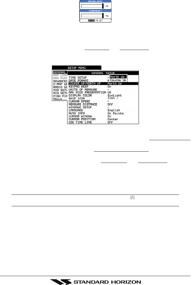
Page 36 CPV350
6.1.4 Changing the backlight and contrast
With the GPS chartplotter turned On, briefly press [PWR] to show the light and contrast
popup window. Move the ShuttlePoint knob to the left or right to adjust the LCD backlight
intensity or up or down to change the LCD contrast. Press [ENT] to set.
Figure 6.1.4 - Backlight and Contrast adjustment
6.1.5 Selecting North Up or Course Up
You may select the Chart page between NORTH UP and COURSE UP which the top of the
Chart page oriented so it will always show the area ahead of the direction your vessel is
traveling.
Figure 6.1.5 - Course Up/North Up menu
1. Press [MENU] two times. Move the ShuttlePoint knob to highlight GENERAL SETUP
and press [ENT] or move the ShuttlePoint knob to the right.
2. Move the ShuttlePoint knob to highlight COURSE UP/NORTH UP and press [ENT] or
move the ShuttlePoint knob to the right.
3. Another popup window will be shown with NORTH UP and COURSE UP, move the
ShuttlePoint knob to the desired selection and press [ENT] or move the ShuttlePoint
knob to the right.
4. Press [CLR] or move the ShuttlePoint knob to the left to exit the menu and show the
Chart page.
NOTE
When the GPS chartplotter is in COURSE UP mode a small arrow icon will be shown on the Chart
page indicating the direction of North.
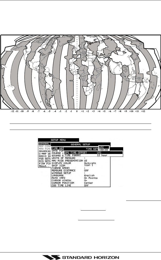
Page 37CPV350
6.2 ADJUSTING THE TIME
The time information supplied by the GPS satellites is in Universal Time Coordinates (UTC
or Greenwich England Mean Time). To change the GPS chartplotter to read the correct
time, first you must figure out the offset and if it is daylight savings time. For example on the
West coast of the United States or Pacific Standard Time the offset needed would be –08:00
or –07:00 for daylight savings time, Eastern Standard Time –05:00 or –04:00 for daylight
savings time.
Figure 6.2 - Adjusting Time
NOTE
This map shows offset for standard time. For daylight saving time, subtract one hour from the offset time.
Figure 6.2a - Time Setup menu
1. Press [MENU] two times. Move the ShuttlePoint knob to highlight GENERAL SETUP
and press [ENT] or move the ShuttlePoint knob to the right.
2. Move the ShuttlePoint knob to highlight TIME SETUP and press [ENT] or move the
ShuttlePoint knob to the right.
3. Move the ShuttlePoint knob to highlight GPS TIME OFFSET and press [ENT] or move
the ShuttlePoint knob to the right.
4. Move the ShuttlePoint knob down to select +00:00, press [ENT] and move the
ShuttlePoint knob to the right to edit the number.
5. Look at the table and find the offset for your area. You will need to enter this offset to
make the GPS chartplotter shows the correct time.
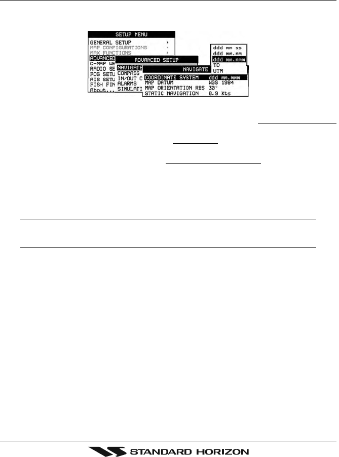
Page 38 CPV350
6. Move the ShuttlePoint knob to the “+”. Move the ShuttlePoint knob up or down to change
to the desired offset.
7. Next move the ShuttlePoint knob to the right to select Hours and move the ShuttlePoint
knob up or down to change the hour.
8. Repeat this method to change the minutes, if necessary.
9. Once you have the correct GPS time offset, press [ENT] to set.
6.3 SELECTING LORAN TD OR OTHER COORDINATE SYSTEM
The GPS Fix coordinates can be changed to show Latitude/Longitude, Loran TD’s or UTM.
Below is the window that will appear when customizing the Coordinate System.
Figure 6.3 - Coordinate System menu
1. Press [MENU] two times. Move the ShuttlePoint knob to highlight ADVANCED SETUP
and press [ENT] or move the ShuttlePoint knob to the right.
2. Move the ShuttlePoint knob to highlight NAVIGATE and press [ENT] or move the
ShuttlePoint knob to the right.
3. Move the ShuttlePoint knob to highlight COORDINATE SYSTEM and press [ENT] or
move the ShuttlePoint knob to the right.
4. Move the ShuttlePoint knob to highlight the desired coordinate type and press [ENT] or
move the ShuttlePoint knob to the right.
5. Press [CLR] or move the ShuttlePoint knob to the left until the Chart page is shown.
NOTE
If the TD is selected, you should set the Chain, Pair, ASF1, ASF2 and Alter. If the TD numbers are
not correct the Pair letters may be backwards. Reversing the two letters usually solves this issue.
Example Y/Z change to Z/Y.
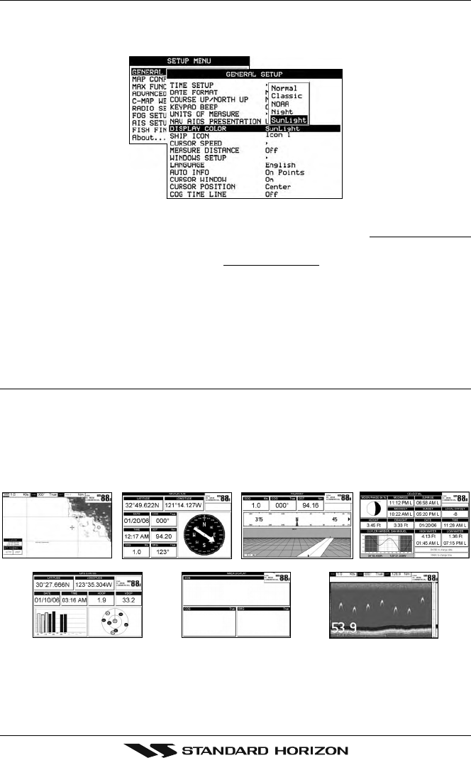
Page 39CPV350
6.4 CHANGING THE CHART COLOR
The GPS chartplotter has preprogrammed settings allowing you to customize the look of the
Chart page. The default is “Sunlight” however there are other settings: Normal, Classic,
NOAA and Night. Night is very useful during evening hours so not to impair night vision.
Figure 6.4 - Display Color menu
1. Press [MENU] two times. Move the ShuttlePoint knob to highlight GENERAL SETUP
and press [ENT] or move the ShuttlePoint knob to the right.
2. Move the ShuttlePoint knob to highlight DISPLAY COLOR and press [ENT] or move the
ShuttlePoint knob to the right.
3. A popup window will be shown with Normal, Classic, NOAA, Night and Sunlight. Move
the ShuttlePoint knob to the desired selection and press [ENT] or move the ShuttlePoint
knob to the right.
4. Press [CLR] or move the ShuttlePoint knob to the left to exit the menu and show the
Chart page.
6.5 SELECTING PAGES USING SOFT KEYS
The Soft Keys located under the LCD are used to select the pages quickly without the need
to go into the menu. The default pages are CHART, NAV, HIGHWAY, CELESTIAL, NMEA
DISPLAY and LIST.
When one of the Soft Keys is pressed popup windows above each Soft Key are shown with
the key description. Press the Soft Key with the desired page description and the GPS
chartplotter will change to that page.
Kts
M
3.1
015° 353°
M
CHART
GPS STATUS
CELESTIAL
NMEA DISPLAY
NAVIGATION HIGHWAY
FISH FINDER full screen window
Shown only with optional F 520 connectedF
Figure 6.5 - Screen display pages
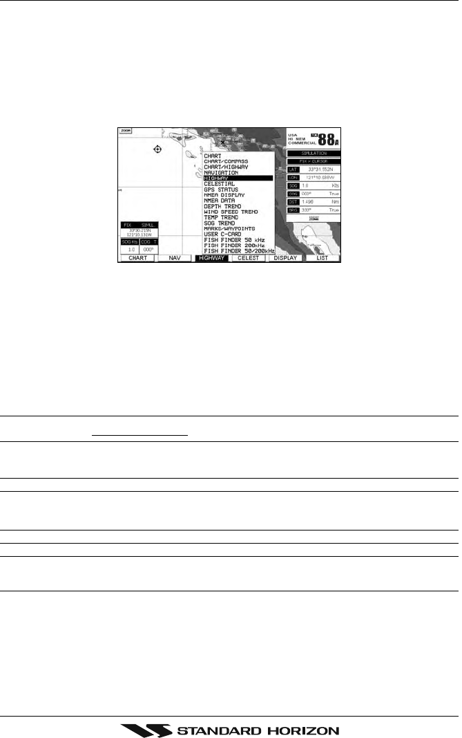
Page 40 CPV350
6.6 CUSTOMIZING THE SOFT KEYS
The Soft Keys can be individually customized from the default pages (discussed above) to
the following: CHART, CHART/COMPASS, CHART/HIGHWAY, NAVIGATION, HIGH-
WAY, CELESTIAL, GPS STATUS, DSC LOG*, DSC DIRECTORY*, NMEA DISPLAY,
NMEA DATA, DEPTH TREND, WIND SPEED TREND, TEMP TREND, SOG TREND,
MARKS/WAYPOINTS and USER C-CARD.
When the Optional FF520 50/200kHz BLACK BOX FISH FINDER is connected, any Soft
Key can be customized to show 50 or 200kHz full page, 50 or 200kHz Chart/Fish split screen
and zoom screens.
Figure 6.6 - Window options of the selected Soft Key
1. To change, momentarily press any of the Soft Keys, then press and hold the Soft Key
you want to customize.
2. A popup window will be shown with the above settings.
3. Move the ShuttlePoint knob up or down to select the desired page.
4. Press [ENT] or move the ShuttlePoint knob to the right to save the page to the selected
Soft Key.
6.7 OTHER SETTINGS IN GENERAL SETUP MENU
You will notice the GENERAL SETUP menu has other selections that allow you to customize:
TIME SETUP Selects a submenu to allow the time setup. It is possible to set the GPS Time Offset,
choosing the UTC or Local Time display, and the Time Format, switching 12 or 24 hours
time format.
DATE FORMAT Allows choosing date format MM-DD-YY or DD-MM-YY.
COURSE UP/NORTH UP Selections are:
North Up : The Top of the page is fixed to North
Course Up : The top of the page is orientated to the direction the vessel is heading.
KEYPAD BEEP Allows the beep produced when a key is pressed to be turned on or off.
UNITS OF MEASURE Units of Measure can be selected for Distance, Speed, Depth, Altitude and Temperature.
NAV AIDS PRESENTATION Allows the Nav Aids presentation to drawn using NOAA symbology when US is selected
or International symbols will be used when International is selected. When selected these
functions affects how the icons for Lights, Signals, Buoys and beacons are displayed.
DISPLAY COLOR Changes the background colors of the chart page to enhance the visibility of the screen
depending on the surrounding light conditions. Normal is recommended when the GPS
chartplotter is not exposed to the direct sunlight. When this mode is set the maps are
displayed in order to use colors as similar as possible to ones used in the original paper
charts. Classic uses vivid chart colors presentation. NOAA allows setting NOAA paper
chart colors presentation. Night is recommended when the environment is dark in order
to reduce the glare of the display. The GPS chartplotter displays maps and screen in
darker colors. Sunlight (default) is designed to enhance the visibility of the screen when
the GPS chartplotter is exposed to sunlight. The maps are much brighter than in the other
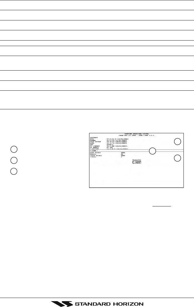
Page 41CPV350
modes and the depth areas are filled with the white color so different depth areas not
easily distinguishable.
SHIP ICON Allows selection of one of 5 choices of ship icons that represent you vessels position
shown on the chart page.
CURSOR SPEED Selects the preferred speed among Low, Medium and High for the cursor in the Chart page
and within the menu.
MEASURE DISTANCE When this function is turned on allows a distance to be measured between two points
using the ShuttlePoint knob and [ENTER] key
WINDOWS SETUP This menu selection allows the data windows to be customized on the Chart and
Navigation pages.
LANGUAGE Allows changing the language for menus and data screens.
AUTO INFO By default when the cursor is moved over a buoy, Mark or other item a popup window will
show information of the item. This menu item allows the window to be turned on or off.
CURSOR WINDOW By default when the cursor is moved a window is shown with the Lat/Lon Distance and
bearing from the vessels location to the cursor. This selection allows the window to be
turned off.
CURSOR POSITION The position of the cursor (vessels location) can be customized so it centered in the middle
or centered on the bottom of the chart page. The default is “Bottom”.
COG TIME LINE Is a line projected from the vessel icon which indicates the distance your vessel will travel
at the current speed. Selections are 2, 10, 30 minutes, 1, 2 hours and infinite.
6.8 INFORMATION PAGE
From Setup Menu page it is possible to select an Information page containing Software,
Chart and Optional devices information.
XXXXXX Version YY.YY
M-NA-M632.00 LOS ANGELES and SAN PEDRO BAYS
Software System Information
1
2
Cartography Information
3
Storage Capacity
3
2
1
Figure 6.8 - Information page
1. Press [MENU] two times. Move the ShuttlePoint knob to highlight About... and press
[ENT] or move the ShuttlePoint knob to the right.
2. The Information page appears on the screen (see the previous Figure).
3. Press [CLR] or move the ShuttlePoint knob to the left to exit and show the Chart page.