Yaesu Musen 30383X20 HANDHELD MARINE TRANSCEIVER User Manual HX280S pmd
Yaesu Musen Co., Ltd. HANDHELD MARINE TRANSCEIVER HX280S pmd
UserManual.wiki
>
Yaesu Musen
>
30383X20 User Manual
Users Manual
Navigation menu
Upload a User Manual
Namespaces
Wiki Guide
HTML
PDF
Info
Views
User Manual
Discussion / Help
Navigation
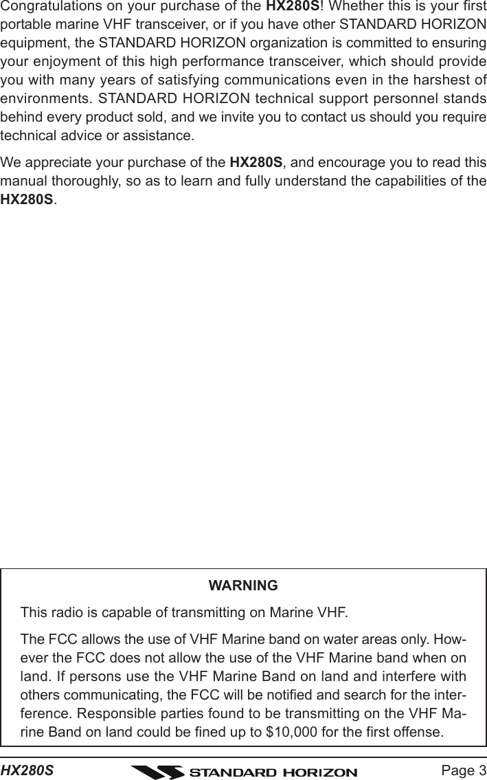
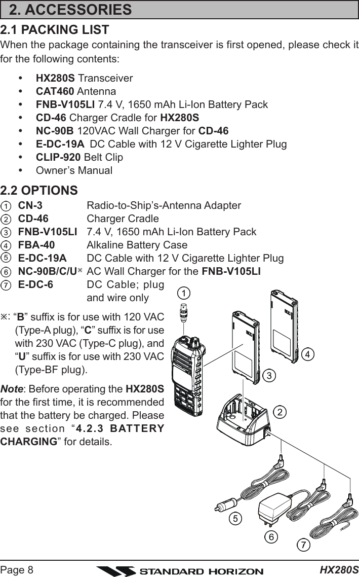
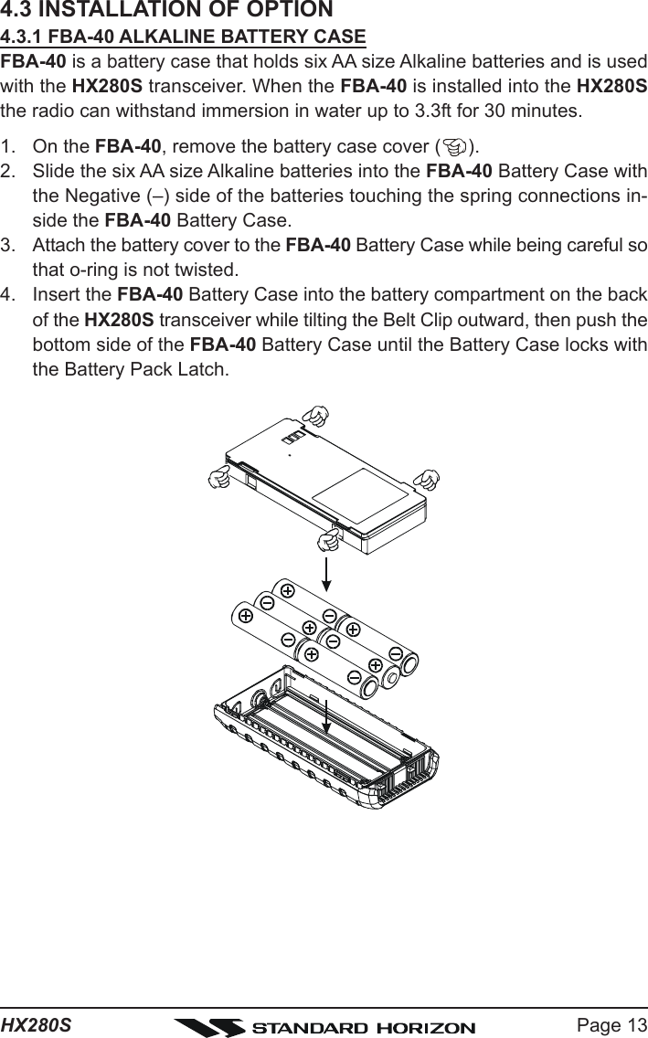
![Page 7HX280S1. GENERAL INFORMATION1.1 INTRODUCTIONThe HX280S is a Submersible 5-Watt portable two way marine transceiver.The transceiver has all allocated USA, International, or Canadian channels. Ithas emergency channel 16 which can be immediately selected from any chan-nel by pressing the [16/9] key. NOAA (National Oceanic and Atmospheric Ad-ministration) Weather channels can also be accessed immediately by press-ing the [WX] key.The HX280S includes the following features: Memory Scanning, Priority Scan-ning, NOAA Weather Alert, Battery Saver, easy-to-read large LCD display,EEPROM memory back-up, Battery Life displayed on LCD, and a transmitTime-Out Timer (TOT).The HX280S transmitter provides a full 5 Watt of transmit power and also isselectable to 1 Watt to assist the user in ensuring maximum battery life.](https://usermanual.wiki/Yaesu-Musen/30383X20/User-Guide-1052779-Page-7.png)
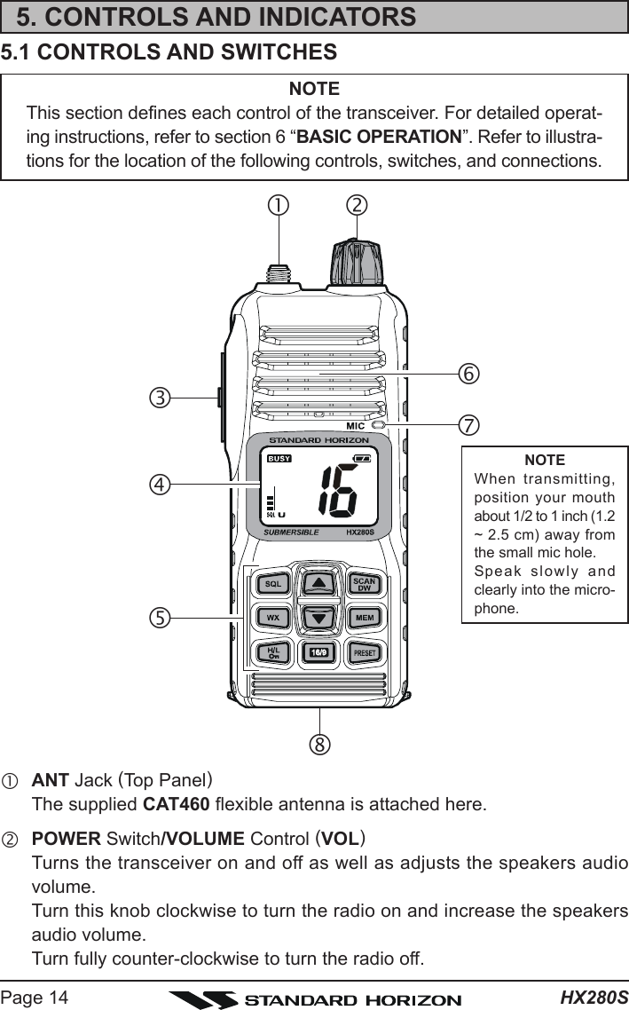
![Page 15HX280SePTT (PUSH-TO-TALK) SwitchWhen pushed activates the transmitter.fLCD DisplayThis display shows current operating conditions, as indicated on the page17.gKeypad[SQL] KeyPress this key to activate the squelch adjusting mode. Press the [T] or [S]key to adjust the squelch threshold level.Press and hold this key for 3 seconds to open the squelch, allowing you tomonitor the operating channel. Release the key to resume normal (quiet)monitoring.[SCAN(DW)] KeyStarts scanning and priority scanning of programmed channels.Secondary use:Press and hold the [SCAN(DW)] key for two seconds to activate the DualWatch feature.[S(UP)] KeyPress the key momentarily to increase the channel one step. Hold the keydown to increase the channel continuously.Secondary use:Used to adjust the squelch threshold level up after the [SQL] key is pressed.[T(DOWN)] KeyPress the key momentarily to decrease the channel one step. Hold the keydown to decrease the channel continuously.Secondary use:Used to adjust the squelch threshold level down after the [SQL] key ispressed.[WX] KeyImmediately recalls the last-used NOAA (National Oceanic and AtmosphericAdministration) Weather Channel from any channel location. Recalls thepreviously- selected working channel when the [WX] key is pressed again.Secondary use:When the [16/9] key is held and the [WX] key is pressed, the radio willchange the marine band between the USA, International, and Canadianchannels.](https://usermanual.wiki/Yaesu-Musen/30383X20/User-Guide-1052779-Page-15.png)
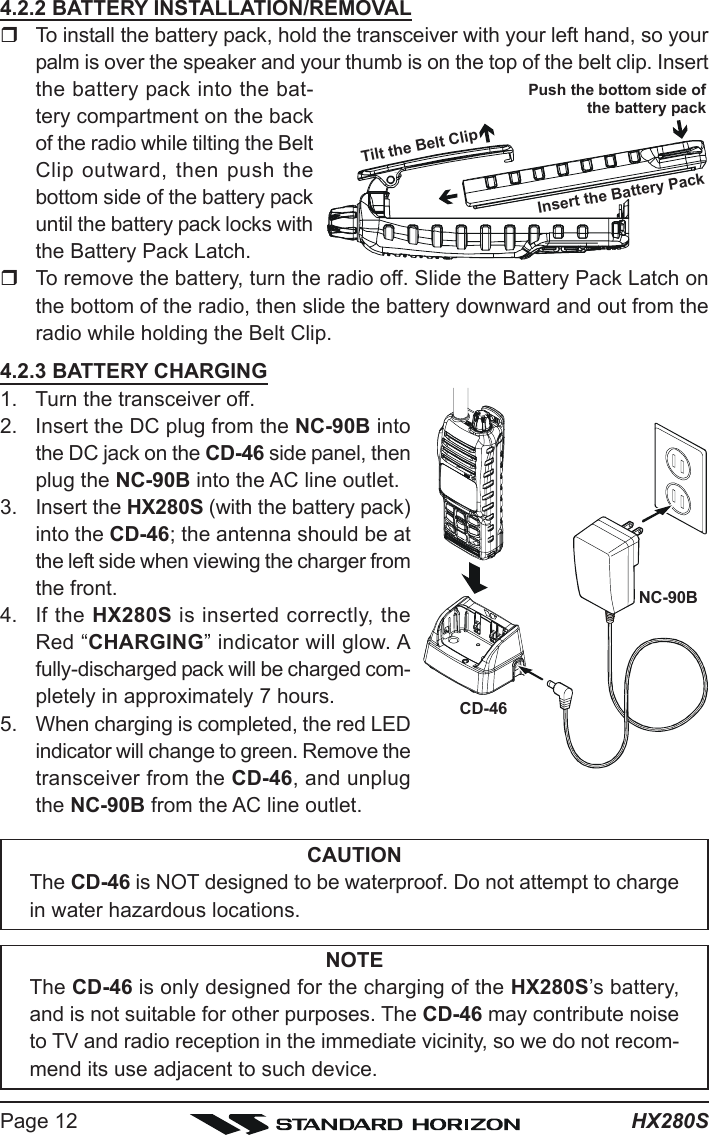
![HX280SPage 16[MEM] KeyPress this key to memorize the selected channel for scanning. Whenpressed a “MEM” icon will be shown on the LCD display indicating thechannel has been saved to scan memory.To delete the channel from scan memory, select the channel and pressthis key until “MEM” is removed from the display.[H/L()] KeyPress this key to toggle the transmitter output power between “High” (5Watts) and “Low” (1 Watt) power. This key does not function on the “Trans-mission Inhibited” and “Low power only” channels.Secondary use:Hold down this key to lock the keypad (except the [SQL], [H/L()] andPTT keys) so that they are not accidentally changed. The “ ” icon willappear at the bottom right corner on the display, to indicate that the func-tions are locked. Hold down this key until the “ ” icon disappears to un-lock the radio.[16/9] KeyPressing this key immediately recalls channel 16 from any channel loca-tion. Holding down this key recalls channel 9. Pressing this key again re-verts to the previous selected working channel.[PRESET] KeyImmediately recalls one of up to 10 user preset memories for each band(shown as “0” - “9” on the LCD). Pressing this key repeatedly scrolls throughthe preset memory channels.hSpeakerThe internal speaker is located here.iMicrophoneThe internal microphone is located here.When transmitting, position your mouth about 1/2 to 1 inch (1.2 ~ 2.5 cm)away from the small mic hole. Speak slowly and clearly into the micro-phone.jBattery Pack Lock (Bottom side)Slide the Battery Pack Lock to the “W” position for battery removal.](https://usermanual.wiki/Yaesu-Musen/30383X20/User-Guide-1052779-Page-16.png)
![Page 17HX280S5.2 LCD INDICATORS“” IndicatorThis indicator appears when a sig-nal is being received.“” IndicatorThis indicator appears during trans-mission.“ / ” IndicatorsThis indicator shows the TX outputpower.“”: High power (5 Watts)“”: Low power (1 Watt).“” IndicatorWhen the “ ” icon is shown on theLCD, all keys are disabled except forthe PTT, [SQL], and [H/L()] keys.“” Battery Indicator“”: Full battery“”: Lower battery“”: Battery is very low“ (Blinking)”: Prepare to chargethe battery“” IndicatorThis indicator appears when the DualWatch is activated.“” Indicator“”: NOAA weather channelis selected.“”: “weather alert” is re-ceived.“MEM” IndicatorThis indicator shows the channel isin the transceiver’s “Scan Memory”.SQL IndicatorThis indicator shows the squelchlevel.“P” IndicatorThis indicator shows the channel isin the “Priority Channel”.“U/I/C” IndicatorThese indicators show the “band” ofoperation for the particular channel.“U” indicates the USA band; “I” indi-cates the International band; and “C”indicates the Canadian band.“SCN” IndicatorThis indicator appears when theScan is activated.Channel DisplayThe operating channel is shown onthe LCD in both the transmission andreception modes.](https://usermanual.wiki/Yaesu-Musen/30383X20/User-Guide-1052779-Page-17.png)
![HX280SPage 186. BASIC OPERATION6.1 PROHIBITED COMMUNICATIONSThe FCC prohibits the following communications:yFalse distress or emergency messages:yMessages to “any boat” except in emergencies and radio tests;yMessages to or from a vessel on land;yTransmission while on land;yObscene, indecent, or profane language (potential fine of $10,000).6.2 INITIAL SETUP1. Install the battery pack on the transceiver (see section “4.2.2 BATTERYINSTALLATION/REMOVAL”).2. Install the antenna onto the transceiver; hold the bottom end of the an-tenna, then screw it onto the mating connector on the transceiver until it issnug. Do not over-tighten.6.3 RECEPTION1. Turn the VOL knob clockwise to turn the transceiver on.2. Press the [SQL] key to activate the squelch adjustingmode (The “SQL” indicator will blink). Press the [T] keyuntil the “ ” indicator will appear on the display,then press the [SQL] key again.3. Turn up the VOL knob until the noise or audio from the speaker is at acomfortable level.4. Press the [SQL] key, then press the [S] key until therandom noise disappears. This state is known as the“Squelch Threshold”.5. Press the [T] or [S] key to select the desired channel.Refer to the channel chart on page 33 for available chan-nels.6. When a signal is received, adjust the VOL knob to thedesired listening level. The “ ” indicator in the LCDis displayed indicating that the channel is being used.](https://usermanual.wiki/Yaesu-Musen/30383X20/User-Guide-1052779-Page-18.png)
![Page 19HX280S6.4 TRANSMISSION1. Perform “6.3 RECEPTION” discussion above.2. Before transmitting, monitor the channel and make sure it is clear.THIS IS AN FCC REQUIREMENT!3. For communications over short distances, press the[H/L()] key to select the Low power (1 watt: “ ” iconappears).Note: Transmitting on Low power prolongs battery life.Low power should be selected whenever possible.4. If using Low power is not effective, select High power(5 watts: “ ” icon appears) by pressing the [H/L()]key.5. When receiving a signal, wait until the incoming signal stops before trans-mitting. The transceiver cannot transmit and receive simultaneously.6. Press the PTT (Push-To-Talk) switch to transmit. Duringtransmission, the “ ” indicator will appear on the dis-play.7. Position your mouth about 1/2 to 1 inch (1.2 ~ 2.5 cm)away from the mic hole. Speak slowly and clearly into the microphone.8. When the transmission is finished, release the PTT switch.6.4.1 TRANSMIT TIME - OUT TIMER (TOT)While the PTT switch is held down, transmission time is limited to 5 minutes.This prevents prolonged (unintentional) transmissions. About 10 seconds be-fore automatic transmitter shutdown, a warning beep will sound from thespeaker. The transceiver automatically switches to the receiving mode, even ifthe PTT switch is held down. Before transmitting again, the PTT switch mustfirst be released, then wait 10 seconds and then pressed again. This Time-Out-Timer (TOT) prevents a continuous transmission that would result from anaccidentally stuck PTT switch.The PTT switch is ignored for 10 seconds after the transceiver auto-matically switches to the receiving mode by the TOT feature.](https://usermanual.wiki/Yaesu-Musen/30383X20/User-Guide-1052779-Page-19.png)
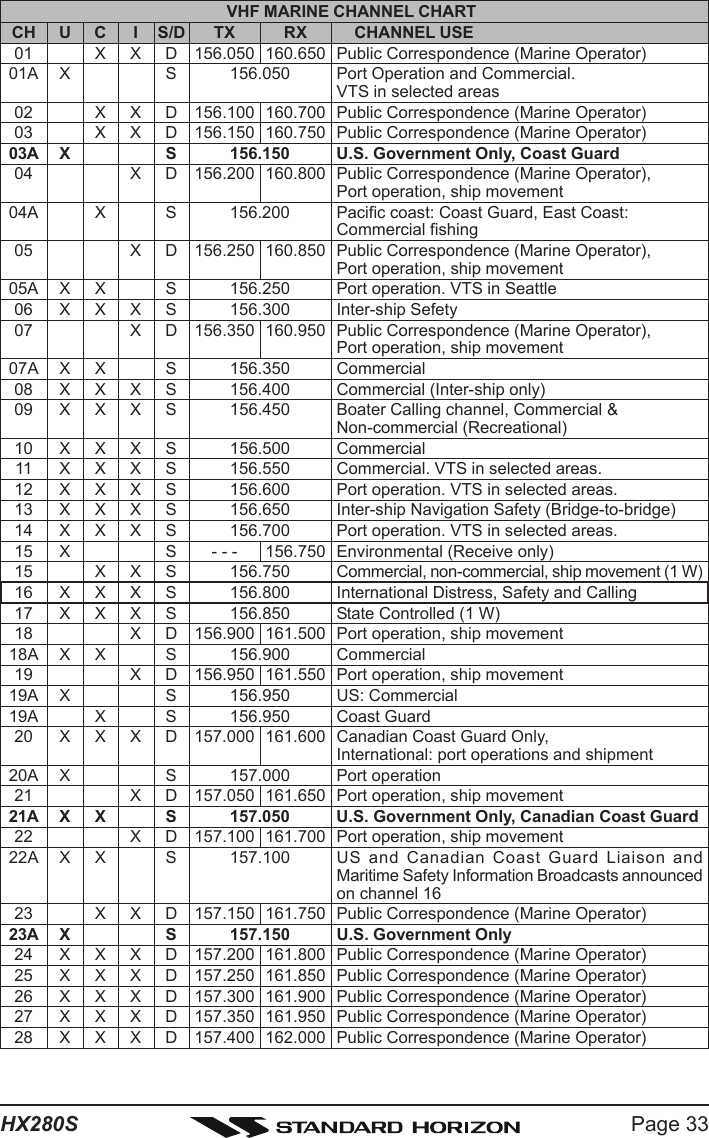
![HX280SPage 206.5 USA, CANADIAN, AND INTERNATIONAL CHANNELS1. To change from US to International or Canadian Marine Channels, holddown the [16/9] key and press the [WX] key. The band will change fromUSA, to International, and to Canadian with each press.2. “U” appears on the LCD for the USA band, “I” appearsfor the International band, and “C” appears for the Ca-nadian band3. Refer to the marine channel charts in section 9 “VHF MARINE CHANNELASSIGNMENTS” for allocated channels.6.6 SIMPLEX/DUPLEX CHANNEL USERefer to the VHF MARINE CHANNEL CHART (page 33) for instructions onuse of simplex and duplex channels.NOTEAll channels are factory-programmed in accordance with FCC (USA),Industry Canada and International regulations. The mode of operationcannot be altered from simplex to duplex or vice-versa. Simplex (ship toship) or duplex (marine operator) mode is automatically activated, de-pending on the channel and whether the USA, International or Cana-dian operating band is selected.6.7 KEYPAD LOCKINGIn order to prevent accidental channel change, the HX280S’s keypad may belocked out.Hold down the [H/L()] key to lock the keypad (except thePTT, [SQL], and [H/L()] keys) so that they are not acci-dentally changed. The “ ” icon will appear on the channelnumber of the display, to indicate that the functions arelocked.Hold down the [H/L()] key until the “ ” icon disappears to unlock the ra-dio.](https://usermanual.wiki/Yaesu-Musen/30383X20/User-Guide-1052779-Page-20.png)
![Page 21HX280S6.8 NOAA WEATHER CHANNELS1. To receive a NOAA (National Oceanic and AtmosphericAdministration) weather broadcast, press the [WX] key.The transceiver changes to the weather channel mode.This mode consists of a preset memory bank containingthe NOAA weather channels.2. When the [WX] key is pressed, the transceiver will be set to the last usedNOAA weather channel. Press the [T] or [S] key to change to other weatherchannels.3. To exit from the weather channel mode, press the [WX] key. The trans-ceiver will revert to the channel you were using prior to switching to theweather channel mode.6.8.1 NOAA WEATHER ALERTIn the event of extreme weather disturbances such as storms and hurricanes,NOAA sends a “weather alert” consisting of a 1050 Hz tone, followed by weatherreports on the weather channels.When a “weather alert” is received on a weather channel,the transceiver emits a beep tone and “ ” icon isshown on the display. Press the [WX] key to stop the beeptone and listen to the weather reports.NOTEOptions for the Weather Alert feature are available, refer to Menu ModeItem “ALt (WX ALERT)” on page 29 for details.6.8.2 NOAA WEATHER ALERT TESTINGIn the event of a major storm or other appreciable weather condition requiringvessels at sea (or other bodies of water) to be notified, the NOAA (NationalOceanographic and Atmospheric Administration) broadcasts a 1050 Hz tonethat some VHF radios, including your HX280S, can detect for “Weather Alarm”purposes (refer to section “6.8.1 NOAA WEATHER ALERT” for a discussionof how to use this feature). The 1050 Hz tone, when detected, will produce aloud beep in the speaker of the HX280S, to signal that a Weather Alert Broad-cast is being received.In order to test this system, NOAA broadcasts the 1050 Hz tone every Wednes-day sometime between 11 AM and 1 PM local time. You may use this opportu-nity to test your HX280S periodically to confirm that the Weather Alert featureis working, or for training crew members on how to configure the HX280S toreceive the NOAA Weather Alerts.](https://usermanual.wiki/Yaesu-Musen/30383X20/User-Guide-1052779-Page-21.png)
![HX280SPage 226.9 PRESET CHANNELS (0 ~ 9): INSTANT ACCESSTen user assigned channels can be programmed for instant access. Pressingthe [PRESET] key activates the user assigned channel bank.6.9.1 PROGRAMMING1. Select the desired channel to be assigned into the Preset Channel Bankusing the [T] or [S] key.2. Press and hold the [PRESET] key until the Preset Chan-nel Number “00000” is shown at the right of the channel num-ber on the display.3. Repeat steps 1 and 2 to program the desired channels into Preset Chan-nels “11111” ~ “99999”.4. To delete a Preset Channel, select the Preset Channel Number to be de-leted using the [T] or [S] key, then press and hold the [PRESET] key untilthe Preset Channel Number is removed from the display.6.9.2 OPERATIONPressing the [PRESET] key will toggle between Preset Channels “00000” through“99999” and the last selected “regular” channel. Preset Channel“00000” is represented by “00000” to the right of the channel numberon the display for one second, and preset channel “11111” isrepresented by “11111” and so forth. The preset channel numberwill disappear after one second.](https://usermanual.wiki/Yaesu-Musen/30383X20/User-Guide-1052779-Page-22.png)
![Page 23HX280S6.10 SCANNINGThe HX280S allows the user to select the scan type from “Memory Scan” or“Priority Scan”. “Memory Scan” scans the channels that were programmedinto memory. “Priority Scan” scans the channels that were programmed intomemory with the priority channel (Channel 16). When an incoming signal isdetected on one of the channels during scan, the radio will pause on thatchannel, allowing you to listen to the incoming transmission.6.10.1 SELECTING THE SCAN TYPE1. Turn the transceiver off by rotating the VOL knob fully counter-clockwise.2. Hold down the [SQL] key, and then turn on the transceiver while still hold-ing down the [SQL] key.3. “SEtSEtSEtSEtSEt” will appear on the display, indicating the Menu(“Set”) Mode has been activated.4. Press the [SQL] key, repeatedly if necessary toselect the Menu item “SCSCSCSCSC”.5. Press the [T] or [S] key to select “PSPSPSPSPS (Priority Scan)” or“MSMSMSMSMS (Memory Scan)”. The factory default is “PSPSPSPSPS(Priority Scan)”.6. After completing your selection, turn the trans-ceiver off and on by rotating the VOL knob.6.10.2 MEMORY SCANNING (M-SCAN)1. Select the desired channel to be included in the scan memory using the[T] or [S] key.2. Press the [MEM] key to store the channel into thetransceiver’s scan memory. “MEM” will be displayed onthe LCD.3. Repeat steps 1 and 2 for all the channels to be scanned.4. To delete a channel from the transceiver’s scan memory, select the memo-rized channel, then press the [MEM] key to delete the channel from scanmemory.5. All channels programmed remain in the transceiver’s scan memory even ifthe power is turned off.6. Adjust the SQL level until background noise is eliminated by pressing the[SQL] key followed by the [T] / [S] key.7. To start scanning, press the [SCAN(DW)] key. The scanproceeds from the lowest to the highest programmedchannel and stops scanning when a transmission is re-ceived. Scanning will resume when the incoming signaldisappears at the end of the transmission. The “MEM” and “SCN” icon will](https://usermanual.wiki/Yaesu-Musen/30383X20/User-Guide-1052779-Page-23.png)
![HX280SPage 24appear at the left of the channel number on the display during scanning.8. To stop the scan, press the [SCAN(DW)] key.6.10.3 PRIORITY SCANNING (P-SCAN)1. Select the desired channel to be included in the scan memory using the[T] or [S] key.2. Press the [MEM] key to store the channel into thetransceiver’s scan memory. “MEM” will be displayed onthe LCD.3. Repeat steps 1 and 2 for all the channels to be scanned.4. To delete a channel from the transceiver’s scan memory, select the memo-rized channel, then press the [MEM] key to delete the channel from scanmemory.5. All channels programmed remain in the transceiver’s scan memory even ifthe power is turned off.6. Adjust the Squelch Level until background noise is eliminated by pressingthe [SQL] key followed by the [T] / [S] key.7. To start scanning, press the [SCAN(DW)] key. A “SCN” icon and blinking“P” and “MEM” icons will appears at the left of the channel number on thedisplay during scanning. The scan proceeds betweenthe memorized channels and the Priority Channel (Chan-nel 16).As an example of priority scanning, let us say that ma-rine channels “06”, “07”, and “08” are memorized in the transceiver’s scanmemory. Priority scanning will proceed in the following sequence:[CH06] Æ (CH16)Ú Æ [CH07] Æ (CH16)Ú Æ[CH08] Æ (CH16)Ú Æ [CH06] Æ (CH16)Ú Æ [CH07] .....Ú: Priority Channel4. Even when the transceiver stops and listens to the signal of a programmedchannel, the transceiver will “dual watch” between this channel and thepriority channel. This allows the radio to be able to receive calls on chan-nel 16 (priority channel) even when the radio is receiving on another chan-nel.5. To stop the Priority Scanning, press the [SCAN(DW)] key.](https://usermanual.wiki/Yaesu-Musen/30383X20/User-Guide-1052779-Page-24.png)
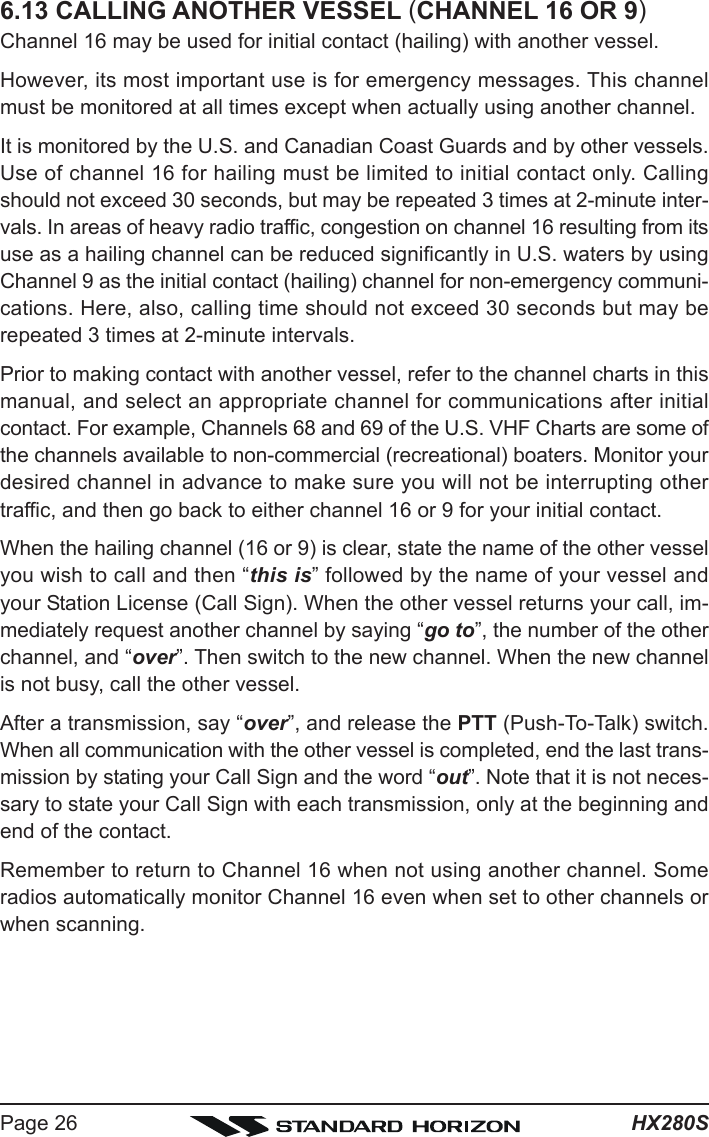
![Page 25HX280S6.11 DUAL WATCHThe Dual Watch feature allows the radio watch the Priority Channel “Channel16” and one other channel.1. Select the desired channel using the [T] or [S] key.2. Press and hold the [SCAN(DW)] key for two seconds toactivate the Dual Watch feature. A “ ” icon will ap-pear on the upper left of the display when the Dual Watchfeature is activated.3. When a transmission is received on the “Priority Channel”, the radio re-ceives the “Priority Channel” until the incoming signal disappears.4. When the radio receives a transmission on the working channel, the radiowill dual watch between the working channel and Channel 16.5. The Dual Watch feature will resume when the incoming signal disappearsat the end of the transmission.6. To stop the Dual Watch feature and return to normal operation, press andhold the [SCAN(DW)] key for two seconds again.6.12 EMERGENCY (CHANNEL 16 USE)Channel 16 is known as the Hail and Distress Channel. An emergency may bedefined as a threat to life or property. In such instances, be sure the trans-ceiver is on and set to “Channel 16”. Then use the following procedure:1. Press the PTT (Push-To-Talk) switch and say “Mayday, Mayday, Mayday.This is _____, _____, _____” (your vessel’s name).2. Then repeat once: “Mayday, _____” (your vessel’s name).3. Now report your position in latitude/longitude, or by giving a true or mag-netic bearing (state which) to a well-known landmark such as a navigationaid or geographic feature such as an island or harbor entry.4. Explain the nature of your distress (sinking, collision, aground, fire, heartattack, life-threatening injury, etc.).5. State the kind of assistance your desire (pumps, medical aid, etc.).6. Report the number of persons aboard and condition of any injured.7. Estimate the present seaworthiness and condition of your vessel.8. Give your vessel’s description: length, design (power or sail), color andother distinguishing marks. The total transmission should not exceed 1minute.9. End the message by saying “OVER”. Release the PTT switch and listen.10. If there is no answer, repeat the above procedure. If there is still no re-sponse, try another channel.](https://usermanual.wiki/Yaesu-Musen/30383X20/User-Guide-1052779-Page-25.png)
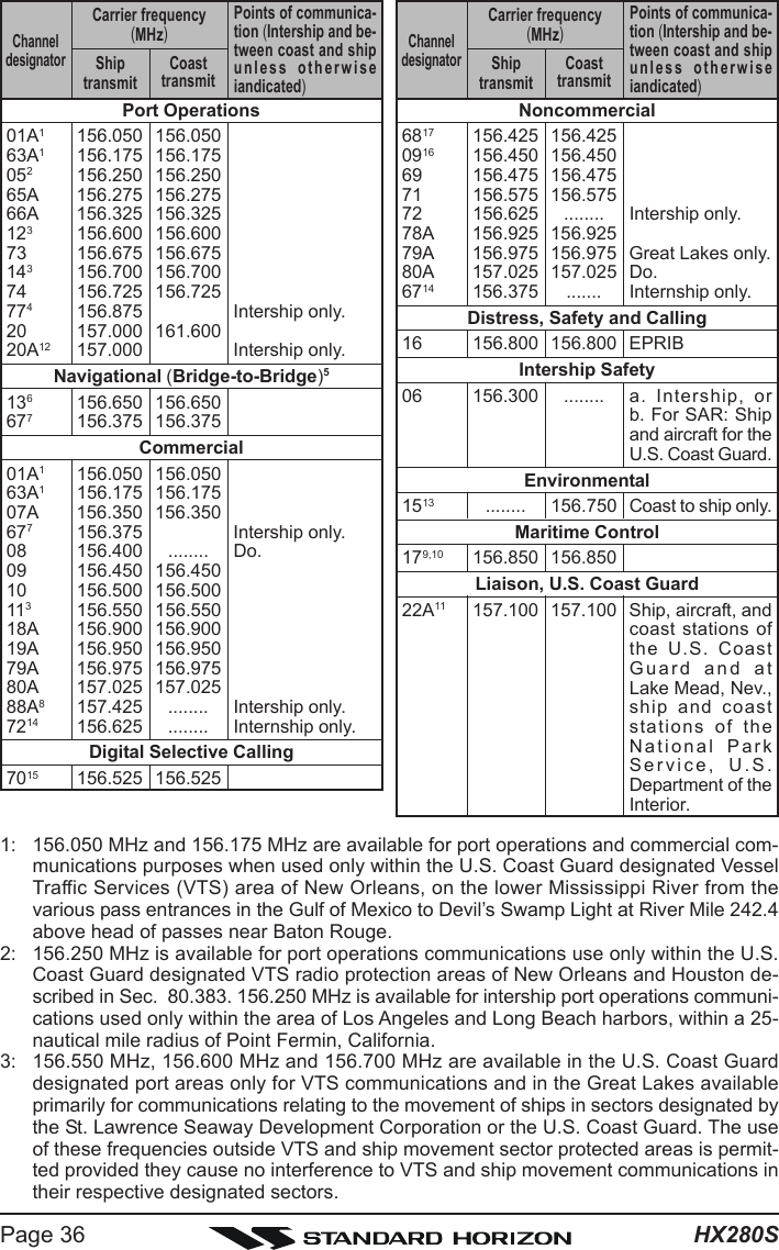
![Page 27HX280S6.14 OPERATING ON CHANNEL 13Channel 13 is used at docks, bridges and for maneuvering in port. Messageson this channel must concern navigation only, such as meeting and passing inrestricted waters. In emergencies and when approaching blind river bends,High power is allowed. Pressing the [H/L()] key will change the power out-put from Low Power (1 Watt) to High (5 Watts). When you change from thischannel then return to it, low power will be automatically selected.6.15 OPERATING ON CHANNEL 67When channel 67 is used for navigational bridge-to-bridge traffic between ships,Normal, High or Medium power may be used temporarily (in the USA band) bypressing the [H/L()] key. When you select this channel again, the trans-ceiver will revert to low power.](https://usermanual.wiki/Yaesu-Musen/30383X20/User-Guide-1052779-Page-27.png)
![HX280SPage 287. MENU (“SET”) MODEThe HX280S’s Menu Mode allows a number of the HX280S operating param-eters to be custom-configured for your operating requirements.The Menu Mode is easy to activate and set, using the following procedure:1. Turn the transceiver off by rotating the VOL knob fully counter-clockwise.2. Hold down the [SQL] key, and then turn on the trans-ceiver while still holding down the [SQL] key.3. “SEtSEtSEtSEtSEt” will appear on the display, indicating the Menu(“Set”) Mode has been activated.4. Press the [SQL] key to select the Menu item to be ad-justed.5. Press the [T] or [S] key to enable adjustment of theselected Menu item. The menu item will blink.6. Press the [SQL] key to select the status or value of theMenu item.7. After completing your adjustment, turn the transceiveroff and on by rotating the VOL knob.LP (LAMP MODE)Function: Selects the Lamp illumination method for the LCD/Keypad.Available Values: on / kEY / oFFDefault: kEYon: Illuminates the LCD/Keypad continuously.kEY: Illuminates the LCD/Keypad for 5 seconds when any key is pressed.oFF: Turns off the backlight for the LCD and keys.bP (BEEP)Function: Enable/Disable the Keypad beeper.Available Values: HI / Lo / oFFDefault: HISC (SCAN TYPE)Function: Selects the Scan mode.Available Values: PS (Priority Scan) / MS (Memory Scan)Default: PS (Priority Scan)](https://usermanual.wiki/Yaesu-Musen/30383X20/User-Guide-1052779-Page-28.png)


![Page 31HX280S8.3 TROUBLESHOOTING CHARTSYMPTOMThe [SCAN(DW)] keydoes not start the scan.Cannot select betweenUSA, INTL, or Canadianbands.Some keys do notoperate.Cannot select keylockfunction.Charging indicator onCD-46 does notillumininate.PROBABLE CAUSENo channels memorized.Squelch is not adjusted.Proper operation notfollowed.Low battery.Audio volume level is too low.Key Lock is on.Proper operation notfollowed.Defective battery FNB-V105LI.REMEDYUse the [MEM] key to enter desiredchannels into the transceiver’smemory.Adjust the squelch to threshold orto the point where noise just dis-appears. Further adjustment of thesquelch control may eliminate in-coming signals.HOLD down the [16/9] key andpress the [WX] key.Charge battery. Refer to section4.2.3 of this manual.Turn the VOL knob clockwise.Turn Key Lock off. Refer to section5.1 of this manual ([H/L()] key).Hold down the [H/L()] key for 2seconds.Contact your Standard Horizondealer.Speaker audio is notheard when the [SQL]key is press and held.](https://usermanual.wiki/Yaesu-Musen/30383X20/User-Guide-1052779-Page-31.png)


![Page 41HX280S11. SPECIFICATIONSPerformance specifications are nominal, unless otherwise indicated, and aresubject to change without notice.11.1 GENERALFrequency Ranges: TX: 156.025 MHz - 157.425 MHzRX: 156.050 MHz - 163.275 MHzChannel Spacing: 25 kHzFrequency Stability: ±5 ppm(–4 °F to +140 °F [–20 °C to +60 °C])Emission Type: 16K0G3EAntenna Impedance: 50 ΩSupply Voltage: 7.4V DC, Negative Ground(Battery Terminal)Current Consumption: 320 mA (Receive, Typical at AF MAX.)50 mA (Standby)1.6 A / 0.7 A (TX: 5 W / 1W)Operating Temperature: –4 °F to +140 °F (–20 °C to +60 °C)Case Size (W x H x D): 2.20” x 5.24” x 1.08” (56 x 133 x 27.5 mm)(w/o knob & antenna)Weight (Approx.): 10.9 oz (310 g)(w/FNB-V105LI, Belt Clip, & Antenna)11.2 TRANSMITTERRF Power Output: 5 W / 1 W (@7.4 V )Modulation Type: Variable ReactanceMaximum Deviation: ±5 kHzSpurious Emission: –75 dBc typicalMicrophone Impedance:2 kΩ11.3 RECEIVERCircuit Type: Double-Conversion SuperheterodyneIntermediate Frequencies: 1st: 21.7 MHz, 2nd: 450 kHzAdjacent Channel Selectivity: 70 dB typicalIntermodulation: 68 dB typicalHum & Noise Ratio: 40 dB typicalSensitivity: 0.25 μV for 12 dB SINADSelectivity: 25 kHz (–70 dB)AF Output (Internal SP): 700 mW @16 Ω for 10 % THD (@7.4 V)Measured in accordance with TIA/EIA-603.](https://usermanual.wiki/Yaesu-Musen/30383X20/User-Guide-1052779-Page-41.png)