Yaesu Musen 30394X20 PORTABLE UHF TRANSCEIVER User Manual HX407 OM
Yaesu Musen Co., Ltd. PORTABLE UHF TRANSCEIVER HX407 OM
UserManual.wiki
>
Yaesu Musen
>
30394X20 User Manual
User Manual
Navigation menu
Upload a User Manual
Namespaces
Wiki Guide
HTML
PDF
Info
Views
User Manual
Discussion / Help
Navigation

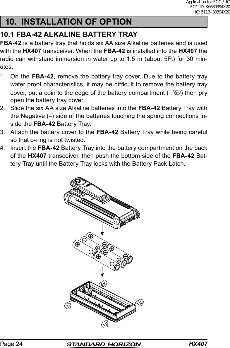
![Page 11HX407 Noise Canceling Microphone The noise canceling microphone is located here. Note: To cancel background noise when transmitting, care should be tak-en not to cover this mic hole with your hand. PTT (PUSH-TO-TALK) Switch When pushed activates the transmitter. LCD Display This display shows current operating conditions. Refer to page 19 for de-tails. Keypad [P-CH], [MON], [P1] - [P4] Key The Programmable key functions can be customized,via programming by your STANDARD HORIZON dealer, to meet your communications/network requirements. Key Press the key momentarily to increase the channel one step. Hold the key down to increase the channel continuously. Key Press the key momentarily to decrease the channel one step. Hold the key down to decrease the channel continuously. Speaker The internal speaker is located here. Microphone The internal microphone is located here. When transmitting, position your mouth 1 inch (2.5 cm) away from the small mic hole. Speak slowly and clearly into the microphone. Battery Pack Lock (Bottom side) Slide the Battery Pack Lock to the “” position for battery removal.Application for FCC / IC FCC ID: K6630394X20 IC: 511B-30394X20](https://usermanual.wiki/Yaesu-Musen/30394X20/User-Guide-2905926-Page-11.png)
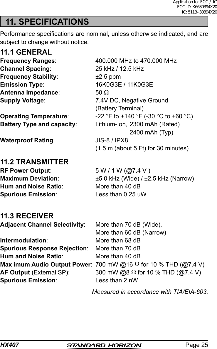
![HX407Page 187. MENU (“SET”) MODEThe Setup Menu allows a number of the HX407 operating parameters to be custom-congured for your operating requirements.The Menu Mode is easy to activate and set, using the following procedure:1. Turn the transceiver off by rotating the VOL knob fully counter-clockwise.2. Hold down the [P1] key, then turn on the transceiver while still holding down the [P1] key.3. The Menu item will scroll on the upper left corner of the display and its current status or value will appear on the large display.4. Press the or key to select the Menu item to be adjusted.5. Press the [P1] key to enable adjustment of the selected Menu item. The current status or value will blink.6. Press the or key to select the desired status or value of the Menu item.7. After completing your adjustment, press the [P3] key to save the new setting.8. If you wish to change another Menu item, repeat steps 4 to 7 above.9. Turn the transceiver off to exit to normal operation.LAMPFunction: Selects the Lamp illumination condition.Available Values: OFF / 2 / 5 / 7 / 10 / 15 (sec)DIMMERFunction: Selects the display brightness level.Available Values: OFF / 1 / 2 / 3 (level)BEEPFunction: Setting the Keypad beep.Available Values: oFF / Lo / Mi / Hi (level)PRI-CHFunction: Select the Priority Channel.Available Values: oFF / Ch NoSCAN TYPEFunction: Selects the Scan Type.Available Values: PS (Pri-Scan) / MS (MEM-Scan)Application for FCC / IC FCC ID: K6630394X20 IC: 511B-30394X20](https://usermanual.wiki/Yaesu-Musen/30394X20/User-Guide-2905926-Page-18.png)