Yaesu Musen 30394X20 PORTABLE UHF TRANSCEIVER User Manual HX407 OM
Yaesu Musen Co., Ltd. PORTABLE UHF TRANSCEIVER HX407 OM
User Manual

HX407
UHF FM Marine Transceiver
Owner’s Manual
Application for FCC / IC
FCC ID: K6630394X20
IC: 511B-30394X20
HX407Page 2
WARNING! FCC RF EXPOSURE REQUIREMENTS
This Radio has been tested and complies with the Federal Communications
Commission (FCC) RF exposure limits for Occupational Use/Controlled
exposure environment. In addition, it complies with the following Standards
and Guidelines:
FCC 96-326, Guidelines for Evaluating the Environmental Effects of Ra-
dio-Frequency Radiation.
FCC OET Bulletin 65 Edition 97-01 (2001) Supplement C, Evaluating
Compliance with FCC Guidelines for Human Exposure to Radio Fre-
quency Electromagnetic Fields.
ANSI/IEEE C95.1-1992, IEEE Standard for Safety Levels with Respect to
Human Exposure to Radio Frequency Electromagnetic Fields, 3 kHz to
300 GHz.
ANSI/IEEE C95.3-1992, IEEE Recommended Practice for the Measure-
ment of Potentially Hazardous Electromagnetic Fields - RF and Micro-
wave.
WARNING:
This radio generates RF electromagnetic energy during transmit mode. This
radio is designed for and classied as Occupational Use Only, meaning
it must be used only during the course of employment by individuals aware
of the hazards, and the ways to minimize such hazards. This radio is not
intended for use by the General Population in an uncontrolled environment.
CAUTION:
To ensure that your expose to RF electromagnetic energy is within the
FCC allowable limits for occupational use, always adhere to the following
guidelines:
This radio is NOT approved for use by the general population in an un-
controlled exposure environment. This radio is restricted to occupational
use, work related operations only where the radio operator must have
the knowledge to control his or her RF exposure conditions.
When transmitting, hold the radio in a vertical position with its micro-
phone 1 inche (2.5 cm) away from your mouth and keep the antenna at
least 1 inches (2.5 cm) away from your head and body.
The radio must be used with a maximum operating duty cycle not ex-
ceeding 50%, in typical Push-to-Talk congurations.
DO NOT transmit for more than 50% of total radio use time (50% duty
cycle). Transmitting more than 50% of the time can cause FCC RF expo-
sure compliance requirements to be exceeded.
Application for FCC / IC
FCC ID: K6630394X20
IC: 511B-30394X20

Page 3HX407
SAR compliance for body-worn use was only demonstrated for the spe-
cic belt-clip (CLIP-22). Other body-worn accessories or congurations
may NOT comply with the FCC RF exposure requirements and should
be avoided.
The CLIP-22 belt-clip must be used in order to comply with the FCC/IC
RF exposure requirements.
Always use Standard Horizon authorized accessories.
The information listed above provides the user with the information need-
ed to make him or her aware of RF exposure, and what to do to assure
that this radio operates with the FCC RF exposure limits of this radio.
Electromagnetic Interference/Compatibility
During transmissions, this radio generates RF energy that can possibly
cause interference with other devices or systems. To avoid such inter-
ference, turn off the radio in areas where signs are posted to do so.
Do not operate the transmitter in areas that are sensitive to electromag-
netic radiation such as hospitals, health care facilities, aircraft, and blast-
ing sites.
Application for FCC / IC
FCC ID: K6630394X20
IC: 511B-30394X20

HX407Page 4
1. GENERAL INFORMATION
1.1 INTRODUCTION
Congratulations on your purchase of the HX407! Whether this is your rst
portable marine UHF transceiver, or if you have other STANDARD HORI-
ZON equipment, the STANDARD HORIZON organization is committed to
ensuring your enjoyment of this high performance transceiver, which should
provide you with many years of satisfying communications even in the harsh-
est of environments. STANDARD HORIZON technical support personnel
stands behind every product sold, and we invite you to contact us should you
require technical advice or assistance.
The HX407 is a JIS-8 / IPX8 (1.5 m (about 5Ft) for 30 minutes) Submersible
2-Watt portable two way marine transceiver with the capability to be pro-
grammed with CTCSS or DCS signalling by a dealer.
The HX407 transmitter provides a full 5 Watt of transmit power and also is
selectable to 1 Watt to assist the user in ensuring maximum battery life.
We appreciate your purchase of the HX407, and encourage you to read this
manual thoroughly, so as to learn and fully understand the capabilities of the
HX407.
1.2 RF EXPOSURE SAFETY STATEMENT
Your wireless handheld portable transceiver contains a low power trans-
mitter. When the Push-To-Talk (PTT: ) button is pushed, the transceiver
sends out radio frequency (RF) signals.
This device is authorized to operate at a duty factor not to exceed 50% (this
corresponds to 50% transmission time and 50% reception time).
This transmitter and its antenna must maintain a separation distance of at
least 1 inch (2.5 cm) from your face. Speak in a normal voice, with the anten-
na pointed up and away from the face at the required separation distance.
Use only the supplied antenna. Unauthorized antennas, modications, or at-
tachments could damage the transmitter.
Application for FCC / IC
FCC ID: K6630394X20
IC: 511B-30394X20

Page 5HX407
2. ACCESSORIES
2.1 PACKING LIST
When the package containing the transceiver is rst opened, please check it
for the following contents:
HX407 Transceiver
SRA-14G/SRA-14H/SRA-14J Antenna
Antenna Gain -2.5 dBi, Impedance 50 ohm
FNB-115LI 7.4 V Li-Ion Battery Pack
CD-50 Charger Cradle for HX407
PA-45B 120VAC Wall Charger for CD-50
Belt Clip
Hand Strap
Owner’s Manual
2.2 OPTIONS
MH-73A4B Speaker/Microphone
MH-57A4B Mini Speaker/Microphone
SSM-64A VOX Headset
SSM-55A Earpiece/Microphone
CN-3 Radio-to-Ship’s Antenna Adapter
CD-50 Charger Cradle
FNB-115LI 7.4 V Li-Ion Battery Pack
FBA-42 Alkaline Battery Case
PA-45B/C/U AC Wall Charger for the FNB-115LI
E-DC-30 DC Cable with 12 V Cigarette Lighter Plug
SAD-1460 6-Unit Multi Charger
: “B” sufx is for use with 120 VAC (Type-A plug), “C” sufx is for use with
230 VAC (Type-C plug), and “U” sufx is for use with 230 VAC (Type-BF
plug).
Note: Before operating the HX407 for the rst time, it is recommended that
the battery be charged. Please see section “3.3.3 BATTERY CHARGING”
for details.
Application for FCC / IC
FCC ID: K6630394X20
IC: 511B-30394X20
HX407Page 6
3. GETTING STARTED
3.1 RADIO CARE
CAUTION
Before following the instructions below, insure the battery pack is in place
and rmly connected. Care must be taken if the radio was dropped and
a close inspection may be needed to insure the radio case and gaskets
are in adequate condition.
The design of the HX407 allows water to enter between the radio and the
battery pack, however waterproof performance is not compromised.
After using the HX407 in salt water environment is recommended to clean
the radio with fresh water by rinsing the battery and radio (separately) under
a sink facet or by dunking in a fresh water. After washing,use a soft cloth to
thoroughly dry all parts of the radio and battery.
This will keep the radio parts and the battery clean and in top operating con-
dition.
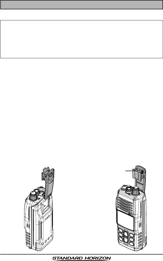
3.2 BELT CLIP INSTALLATION AND REMOVAL
To install the Belt Clip: align the
Belt Clip to the groove of the Bat-
tery pack, then press the Belt Clip
downward until it locks in place
with a “Click.”
To remove the Belt Clip: press the
Belt Clip Tab away from the bat-
tery pack to unlock the Belt Clip,
then slide the Belt Clip upward to
remove it.
Belt Clip Tab
Application for FCC / IC
FCC ID: K6630394X20
IC: 511B-30394X20

Page 7HX407
3.3 BATTERIES AND CHARGERS
If the radio has never been used, or its charge is depleted, it may be
charged by connecting the CD-50 Charger Cradle with the PA-45B Battery
Charger, as shown in the illustration. If 12V DC power is available, the sup-
plied E-DC-30 DC Cable with 12 V Cigarette Lighter Plug may be used for
charging the battery. The PA-45B and E-DC-30 will charge a completely dis-
charged FNB-115LI battery pack in approximately 3 hours.
The FNB-115LI is a high performance Li-Ion battery providing high capacity
in a compact package.
CAUTION
To avoid risk of explosion and injury, FNB-115LI battery pack should only
be removed, charged or recharged in non-hazardous environments.
3.3.1 BATTERY SAFETY
Battery packs for your transceiver contain Li-Ion batteries. This type of bat-
tery stores a charge powerful enough to be dangerous if misused or abused,
especially when removed from the transceiver. Please observe the following
precautions:
DO NOT SHORT BATTERY PACK TERMINALS: Shorting the terminals
that power the transceiver can cause sparks, severe overheating, burns, and
battery cell damage. If the short is of sufcient duration, it is possible to melt
battery components. Do not place a loose battery pack on or near metal sur-
faces or objects such as paper clips, keys, tools, etc. When the battery pack
is installed on the transceiver, the terminals that transfer current to the trans-
ceiver are not exposed. The terminals that are exposed on the battery pack
when it is mounted on the transceiver are charging terminals only and do not
constitute a hazard.
DO NOT INCINERATE: Do not dispose of any battery in a re or incinerator.
The heat of re may cause battery cells to explode and/or release dangerous
gases.
Battery Maintenance
For safe and proper battery use, please observe the following:
Battery packs should be charged only in non-hazardous environments;
Use only STANDARD HORIZON-approved batteries;
Use only a STANDARD HORIZON approved charger. The use of any
other charger may cause permanent damage to the battery.
Follow charging instructions provided with the chargers.
Keep the battery contacts clean and dry.
Application for FCC / IC
FCC ID: K6630394X20
IC: 511B-30394X20
HX407Page 8
Battery Storage
Store the batteries in a cool place to maximize storage life. Since batteries
are subject to self-discharge, avoid high storage temperatures that cause
large self-discharge rates. After extended storage, a full recharge is recom-
mended.
Battery Recycling
DO NOT PLACE USED BATTERIES IN YOUR REGULAR TRASH!
LI-ION BATTERIES MUST BE COLLECTED, RECYCLED OR DISPOSED
OF IN AN ENVIRONMENTALLY SOUND MANNER.
The incineration, land lling or mixing of Li-Ion batteries with the municipal
solid waste stream is PROHIBITED BY LAW in most areas.
Return batteries to an approved Li-Ion battery recycler. This may be where
you purchased the battery.
Contact your local waste management ofcials for other information regard-
ing the environmentally sound collection, recycling and disposal of Li-Ion bat-
teries.
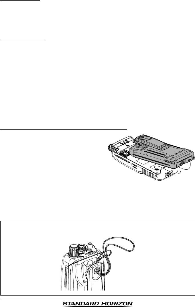
3.3.2 BATTERY INSTALLATION AND REMOVAL
To install the battery pack, hold the
transceiver with your left hand, so
your palm is over the speaker. In-
sert the battery pack into the battery
compartment on the back of the ra-
dio, then push the bottom side of the
battery pack until the battery pack
locks with the Battery Pack Latch.
To remove the battery, turn the radio off. Slide the Battery Pack Latch on
the bottom of the radio, then lift up on the bottom of the battery and re-
move it from the radio.
HAND STRAP INSTALLATION
Application for FCC / IC
FCC ID: K6630394X20
IC: 511B-30394X20
Page 9HX407
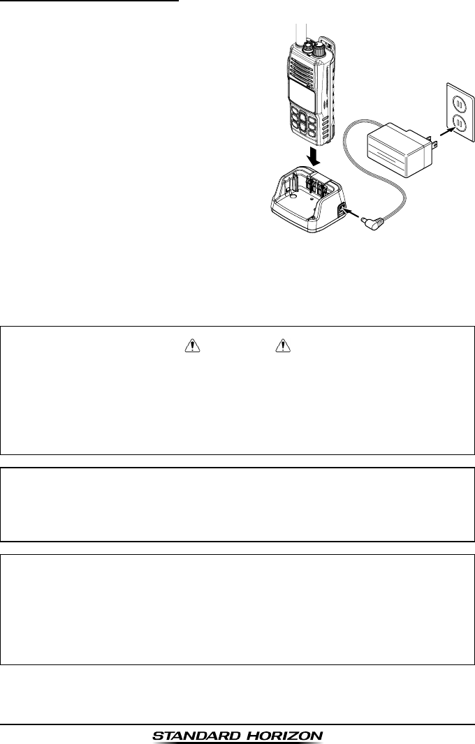
3.3.3 BATTERY CHARGING
1. Turn the transceiver off.
2. Insert the DC plug from the PA-45B
into the DC jack on the CD-50 side
panel, then plug the PA- 45B into the
AC line outlet.
3. Insert the HX407 (with the battery
pack) into the CD-50; the antenna
should be at the left side when view-
ing the charger from the front.
4. If the HX407 is inserted correctly,
the Red “CHARGING” indicator will
glow. A fully-discharged pack will be
charged completely in approximately
3 hours.
5. When charging is completed, the red LED indicator will change to green.
Remove the transceiver from the CD-50, and unplug the PA-45B from
the AC line outlet.
WARNING
Do not reverse-connect the battery terminals.
Do not parallel-connect the battery terminals.
Do not change batteries in hazardous locations.
To reduce the risk of explosion, recharge the batteries outside of
hazardous locations.
CAUTION
The CD-50 cradle is NOT designed to be waterproof. Do not attempt to
charge in water hazardous locations.
NOTE
The CD-50 cradle is only designed for the charging of the HX407’s bat-
tery, and is not suitable for other purposes. The CD-50 may contribute
noise to TV and radio reception in the immediate vicinity, so we do not
recommend its use adjacent to such device.
PA-45B
CD-50
Application for FCC / IC
FCC ID: K6630394X20
IC: 511B-30394X20
HX407Page 10
P-CH
MON
P4 P3
P2
P1
HX407
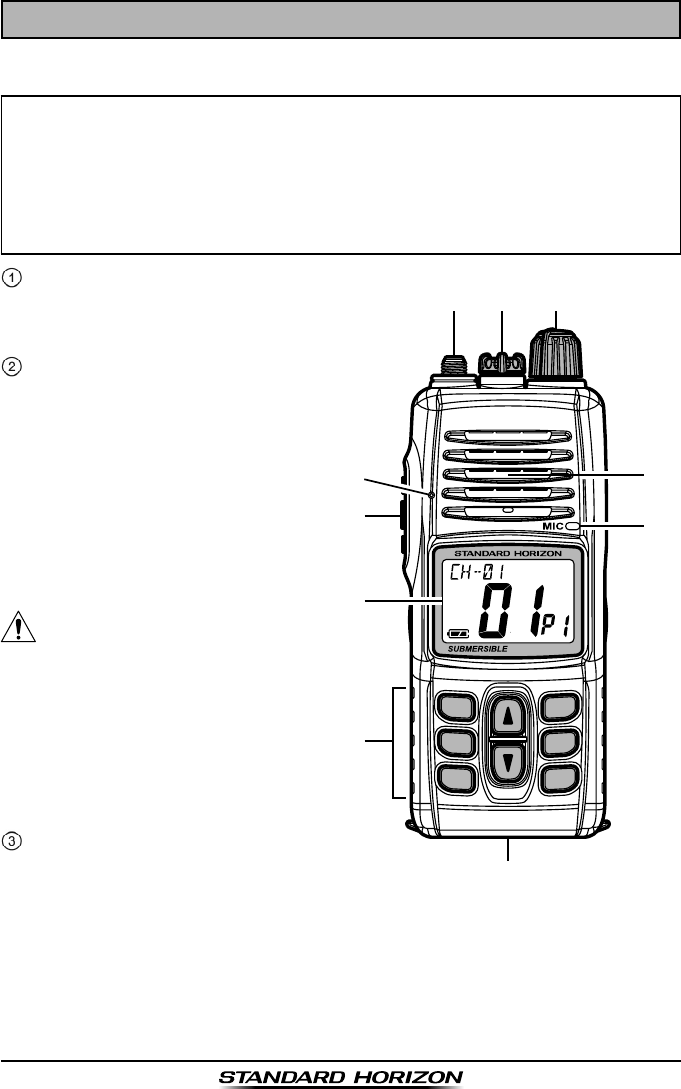
4. COTROLS AND INDICATORS
4.1 CONTROLS AND SWITCHES
NOTE
This section denes each control of the transceiver. For detailed operat-
ing instructions, refer to section “6. BASIC OPERATION”. Refer to illus-
trations for the location of the following controls, switches, and connec-
tions.
ANT Jack (Top Panel)
The supplied CAT460 flexible
antenna is attached here.
MIC/SP Jack (Top Panel)
The jack accepts the optional
MH-73A4B Speaker/Micro-
phone, MH-57A4B Mini Speak-
er/Microphone, SSM-64A
VOX Headset, or SSM-55A
Earpiece/Microphone. When
this jack is used, the internal
speaker and microphone are
disabled.
1) Do not allow the HX407 to
become submerged in water
while the plastic cover over
the MIC/SP jack is removed.
2) Do not remove/install the
optional Speaker Micro-
phone in a hazardous loca-
tion.
POWER Switch / VOLUME
Control (VOL)
Turns the transceiver on and
off as well as adjusts the audio volume level.
Turn this knob clockwise to turn the radio on and increase the speakers
audio volume.
Turn fully counter-clockwise to turn the radio off.
Application for FCC / IC
FCC ID: K6630394X20
IC: 511B-30394X20
Page 11HX407
Noise Canceling Microphone
The noise canceling microphone is located here.
Note: To cancel background noise when transmitting, care should be tak-
en not to cover this mic hole with your hand.
PTT (PUSH-TO-TALK) Switch
When pushed activates the transmitter.
LCD Display
This display shows current operating conditions. Refer to page 19 for de-
tails.
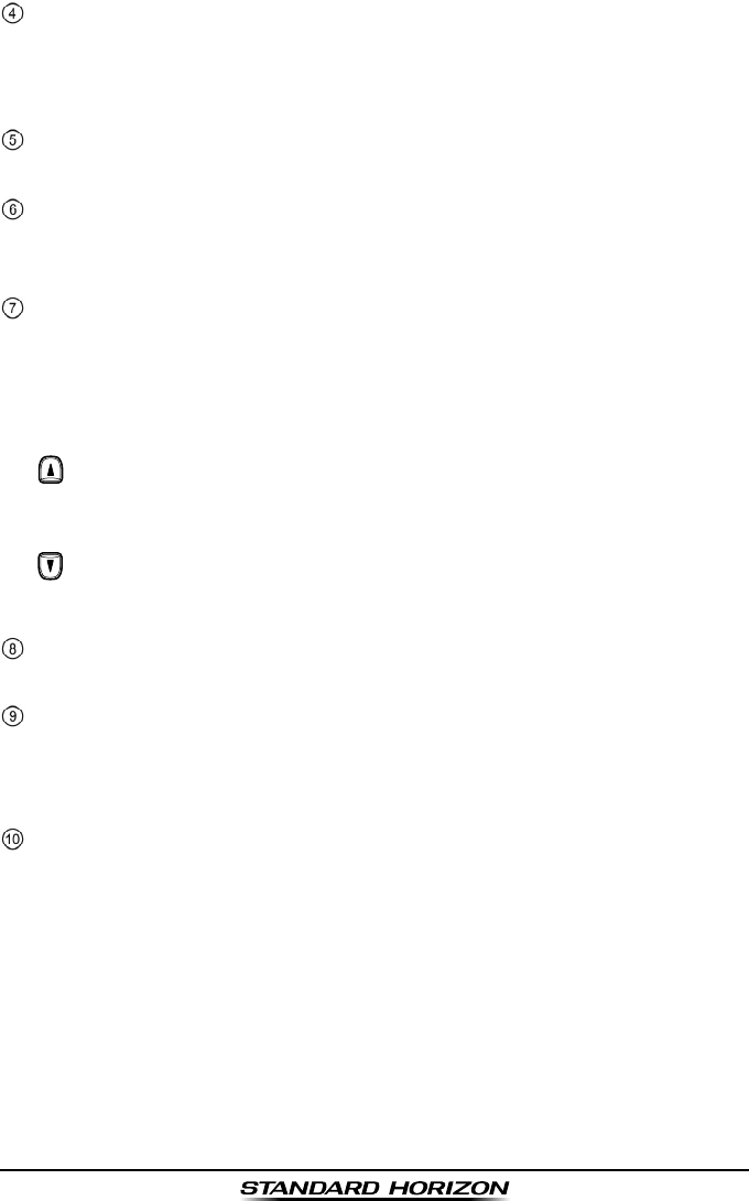
Keypad
[P-CH], [MON], [P1] - [P4] Key
The Programmable key functions can be customized,via programming
by your STANDARD HORIZON dealer, to meet your communications/
network requirements.
Key
Press the key momentarily to increase the channel one step. Hold the
key down to increase the channel continuously.
Key
Press the key momentarily to decrease the channel one step. Hold the
key down to decrease the channel continuously.
Speaker
The internal speaker is located here.
Microphone
The internal microphone is located here.
When transmitting, position your mouth 1 inch (2.5 cm) away from the
small mic hole. Speak slowly and clearly into the microphone.
Battery Pack Lock (Bottom side)
Slide the Battery Pack Lock to the “” position for battery removal.
Application for FCC / IC
FCC ID: K6630394X20
IC: 511B-30394X20
HX407Page 12
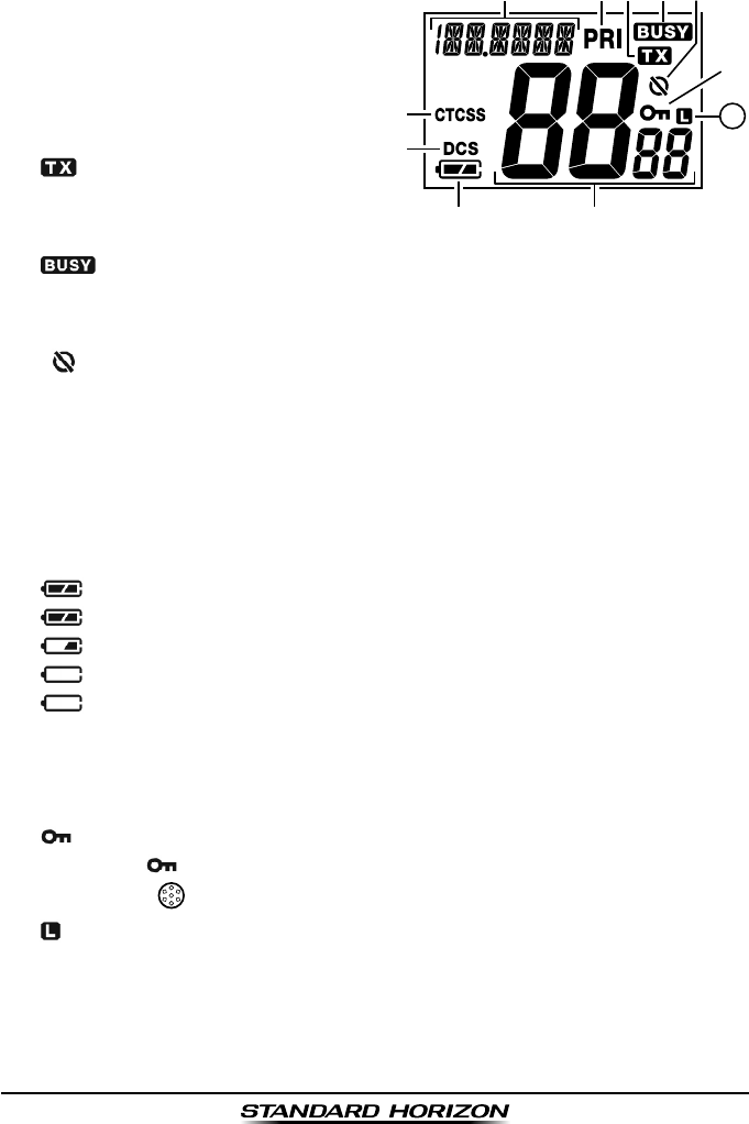
4.2 LCD INDICATORS
① Alpha/numeric “Tag” display
Indicates the current channel
name or operating mode.
② “PRI” Indicator
This indicator is shown when the
Priority channel is selected.
③ “ ” Indicator
This indicator appears during
transmission.
④ “ ” Indicator
This indicator appears when a signal is being received or when the radio
is unsquelched.
⑤ “ ” Indicators
This indicator shows the Voice Scrambler function is assigned to a chan-
nel.
⑥ “CTCSS” Indicator
This indicator shows the CTCSS function is assigned to a channel.
⑦ “DCS” Indicator
This indicator shows the DCS function is assigned to a channel.
⑧ “ ” Battery Indicator
“ ”: Full battery
“ ”: Lower battery
“ ”: Battery is very low
“ (Blinking)”: Prepare to charge the battery
⑨ Channel Display
The operating channel is shown on the LCD in both the transmission and
reception modes.
⑩ “ ” Indicator
When the “ ” icon is shown on the LCD, all keys are disabled except
for the PTT ( ) key.
⑪ “ ” Indicators
This indicator shows when the TX output power is selected to “Low”
(1 Watt) power.
11
Application for FCC / IC
FCC ID: K6630394X20
IC: 511B-30394X20

Page 13HX407
MEMO
Application for FCC / IC
FCC ID: K6630394X20
IC: 511B-30394X20
HX407Page 14
5. BASIC OPERATION
5.1 INITIAL SETUP
1. Install the battery pack on the transceiver (see section “3.3.2 BATTERY
INSTALLATION AND REMOVAL”).
2. Install the antenna onto the transceiver; hold the bottom end of the an-
tenna, then screw it onto the mating connector on the transceiver until it
is snug. Do not over-tighten.
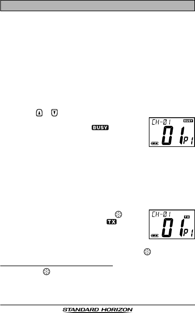
5.2 RECEPTION
1. Turn the VOL knob clockwise to turn the transceiver on.
The battery voltage will appear briey at the upper left corner on the dis-
play, then the channel name will appear.
2. Turn the VOL knob clockwise until the noise or audio from the speaker is
at a comfortable level.
3. Press the or key to select the desired channel.
4. When a signal is received, adjust the VOL knob to
the desired listening level. The “ ” indicator on
the LCD is displayed indicating that the channel is
being used.
5.3 TRANSMISSION
1. Perform “5.2 RECEPTION” discussion above.
2. Before transmitting, monitor the channel and make sure it is clear.
THIS IS AN FCC REQUIREMENT!
3. When receiving a signal, wait until the incoming signal stops before
transmitting. The transceiver cannot transmit and receive simultaneous-
ly.
4. Press and hold the PTT (Push-To-Talk: ) switch
to transmit. During transmission, the “ ” indicator
will appear on the display.
5. Position your mouth 1 inch (2.5 cm) away from the
mic hole. Speak slowly and clearly into the microphone.
6. When the transmission is nished, release the PTT () switch.
5.3.1 TRANSMIT TIME - OUT TIMER (TOT)
While the PTT () switch is held down, transmission time is limited to 5
minutes. This prevents prolonged (unintentional) transmissions. About 10
seconds before automatic transmitter shutdown, a warning beep will sound
from the speaker. The transceiver automatically switches to the receiving
Application for FCC / IC
FCC ID: K6630394X20
IC: 511B-30394X20
Page 15HX407
mode, even if the PTT ( ) switch is held down. Before transmitting again,
the PTT ( ) switch must rst be released. This Time-Out-Timer (TOT) pre-
vents a continuous transmission that would result from an accidentally stuck
PTT ( ) switch.
NOTE
The PTT ( ) switch is disabled for 10 seconds after the transceiver au-
tomatically switches to the receiving mode by the TOT feature.
Application for FCC / IC
FCC ID: K6630394X20
IC: 511B-30394X20
HX407Page 16
6. ADVANCED OPERATION
6.1 Programmable Key Functions
The Programmable key functions can be customized, via programming by
your STANDARD HORIZON dealer, to meet your communications/network
requirements.
The possible Programmable key programming features are illustrated on the
next page, and their functions are explained beginning after page 18. For fur-
ther details, contact your STANDARD HORIZON dealer.
P-ch
Press (or press and hold) the assigned programmable key to recall the
pre-programmed priority channel.
Sql Set
You can manually adjust the squelch level using this function.
Sql Mute off
Press (or press and hold) the assigned Programmable key to cancel any sig-
naling features; the “ ” indicator will appears on the display.
Tx Power H/L
Press to toggle the transmit power between High (5 W) and Low (1 W).
Ch Up/DN
Press (or press and hold) the assigned Programmable key to select a differ-
ent channel within the current Group.
Ch Continuation Up/Dn
Press and hold the assigned programmable key causes the radio to begin
stepping (repeatedly) upward or downward through the channels.
Key Lock
In order to prevent accidental channel change, the HX407’s keypad may be
locked.
Lamp
Press (or press and hold) the assigned Programmable key to illuminate the
display for ve seconds.
Scan
The Scanning feature is used to monitor multiple signals programmed into
the transceiver. While scanning, the transceiver will check each channel for
the presence of a signal, and will stop on a channel if a signal is present.
Application for FCC / IC
FCC ID: K6630394X20
IC: 511B-30394X20

Page 17HX407
Dual Watch
The Dual Watch feature allows the radio to scan between the Priority Chan-
nel and one other channel.
Noise Cancel
Press (or press and hold) the assigned Programmable key to toggle the
Noise Cancel feature “On” and “Off”.
Scrambler
Press (or press and hold) the assigned Programmable key to toggle the En-
cryption feature “On” and “Off”.
Vox
Press (or press and hold) the assigned programmable key to turn the VOX
function “On” or “Off”. You may disable the VOX function temporarily by
pressing the PTT switch.
Group Change Up/Dn
Press (or press and hold) the assigned Programmable key to select a differ-
ent Group channel.
Tx Save Disable
Press (or press and hold) the assigned Programmable key to disable the TX
Save feature.
Group Scan On/Off
Press (or press and hold) the assigned Programmable key to toggle the
Group Scan feature “On” and “Off”.
Ta Scan
Press (or press and hold) the assigned Programmable key to toggle the TA
(Talk Around) scan feature “On” and “Off”.
Talk Around
Press (or press and hold) the assigned Programmable key to activate the
Talk Around feature.
Direct Ch1 - 4
Press (or press and hold) the assigned Programmable key to recall the Deal-
er pre-programmed channel directly.
Application for FCC / IC
FCC ID: K6630394X20
IC: 511B-30394X20
HX407Page 18
7. MENU (“SET”) MODE
The Setup Menu allows a number of the HX407 operating parameters to be
custom-congured for your operating requirements.
The Menu Mode is easy to activate and set, using the following procedure:
1. Turn the transceiver off by rotating the VOL knob fully counter-clockwise.
2. Hold down the [P1] key, then turn on the transceiver while still holding
down the [P1] key.
3. The Menu item will scroll on the upper left corner of the display and its
current status or value will appear on the large display.
4. Press the or key to select the Menu item to be adjusted.
5. Press the [P1] key to enable adjustment of the selected Menu item. The
current status or value will blink.
6. Press the or key to select the desired status or value of the Menu
item.
7. After completing your adjustment, press the [P3] key to save the new
setting.
8. If you wish to change another Menu item, repeat steps 4 to 7 above.
9. Turn the transceiver off to exit to normal operation.
LAMP
Function: Selects the Lamp illumination condition.
Available Values: OFF / 2 / 5 / 7 / 10 / 15 (sec)
DIMMER
Function: Selects the display brightness level.
Available Values: OFF / 1 / 2 / 3 (level)
BEEP
Function: Setting the Keypad beep.
Available Values: oFF / Lo / Mi / Hi (level)
PRI-CH
Function: Select the Priority Channel.
Available Values: oFF / Ch No
SCAN TYPE
Function: Selects the Scan Type.
Available Values: PS (Pri-Scan) / MS (MEM-Scan)
Application for FCC / IC
FCC ID: K6630394X20
IC: 511B-30394X20

Page 19HX407
SCAN MEMORY
Function: Add or remove a channel to Scan Memory.
NOISE CANCEL TX
Function: Enables/Disables the TX Noise Canceling function.
Available Values: on / oFF
NOISE CANCEL RX
Function: Enables/Disables the RX Noise Canceling function.
Available Values: oFF / 1 / 2 / 3 / 4 (level)
AF PITCH CONTL
Function: Selects the audio lter operation.
Available Values: oFF / HLc / HLb / Lb / Hb
VOICE SCRAMBLER
Function: Enables/Disables the Voice Scrambler and selects its scramble
code.
Available Values: oFF / 0 to 31
VOX
Function: Enables/Disables the VOX function.
Available Values: oFF / 0 to 31
VOX SENSE
Function: Select the VOX gain.
Available Values: 1 / 2 / 3 / 4 / 5 (level)
VOX TIMER
Function: Select the VOX delay time.
Available Values: 1 / 2 / 3 / 4 / 5 (sec)
Application for FCC / IC
FCC ID: K6630394X20
IC: 511B-30394X20

HX407Page 20
8. MAINTENANCE
8.1 GENERAL
The inherent quality of the solid-state components in STANDARD HORIZON
radios will provide many years of continuous use. Take the following precau-
tions to prevent damage to the radio.
To prevent corrosion of electrical contacts and keep the water resis-
tance, keep the microphone or the jack connected at all times.
Never press the PTT switch unless an antenna or suitable dummy load
is connected to the antenna receptacle.
Ensure that the input voltage does not exceed the value specied in your
Owner’s Manual.
Use only STANDARD HORIZON-approved accessories and replace-
ment parts.
8.2 REPLACEMENT PARTS
Occasionally an owner needs a replacement part. Items can be ordered from
our Parts Department by writing or calling (in USA or Canada), or Standard
Horizon/Yaesu authorized dealers (outside USA or Canada).
Marine Division of YAESU U.S.A.
6125 Phyllis Drive, Cypress, CA 90630, U.S.A.
Telephone (800) 767-2450
8.3 FACTORY SERVICE
In the unlikely event that the radio fails to perform or needs servicing, please
contact the following:
For repairs In USA
Standard Horizon
Attention Marine Repair Department
6125 Phyllis Drive, Cypress, CA 90630
Telephone (800) 366-4566
For repairs In Canada
Westcom Marine
488 East 62 nd Avenue
Vancouver BC V5X2G1
Telephone (604) 327-6280
Application for FCC / IC
FCC ID: K6630394X20
IC: 511B-30394X20

Page 21HX407
9. WARRANTY
Marine Products Limited Warranty
PLEASE NOTE
The following “Limited Warranty” is for valid for products that have
been purchased in the United States and Canada. For limited War-
ranty details outside the United States, contact the dealer in your
country.
STANDARD HORIZON (a division of YAESU U.S.A.) warrants, to the original
purchaser only, each new Marine Communications Product (“Product”) man-
ufactured and/or supplied by STANDARD HORIZON against defects in ma-
terials and workmanship under normal use and service for a period of time
from the date of purchase as follows:
Fixed Mount and Portable Transceivers
1 year - if purchased before 01/01/91
3 years - if purchased between 01/01/91 and 01/01/94
3 years Waterproof - if purchased after 01/01/94
Loud hailers
1 year - if purchased before 01/01/91
3 years - if purchased after 01/01/91
Associated Chargers
1 year - if purchased before 01/01/91
3 years - if purchased after 01/01/91
Associated Batteries - 1 year. Note: Batteries will be deemed deective only
if storage capacity drops below 80% of rated capacity or if leakage develops.
Associated Accessories - 1 year. Includes: Microphones/Handsets, External
Speakers, Antennas, Carrying Accessories, Power Supplies, and Signaling Boards.
To receive warranty service, the purchaser must deliver the Product, trans-
portation and insurance prepaid, to STANDARD HORIZON (a division of
YAESU U.S.A.), Attention Marine repairs 6125 Phyllis Drive, Cypress, CA
90630. Include proof of purchase indicating model. serial number, and date
of purchase. STANDARD HORIZON will return the Product to the purchaser
freight prepaid. Products purchased prior to January 1, 1991 will bear the
STANDARD HORIZON warranty terms in effect prior to that date.
In the event of a defect, malfunction or failure of the Product during the war-
ranty period, STANDARD HORIZON’s liability for any breach of contract or
any breach of express or implied warranties in connection with the sale of
Products shall be limited solely to repair or replacement, at its option, of the
Application for FCC / IC
FCC ID: K6630394X20
IC: 511B-30394X20

HX407Page 22
Product or part(s) therein which, upon examination by STANDARD HORI-
ZON, appear to be defective or not up to factory specications. STANDARD
HORIZON may, at its option, repair or replace parts or subassemblies with
new or reconditioned parts and subassemblies. Parts thus repaired or re-
placed are warranted for the balance of the original applicable warranty.
STANDARD HORIZON will not warrant installation, maintenance or service
of the Products. In all instances, STANDARD HORIZON’s liability for damag-
es shall not exceed the purchase price of the defective Product.
This warranty only extends to Products sold within the 50 States of the Unit-
ed States of America and the District of Columbia.
STANDARD HORIZON will pay all labor to repair the product and replace-
ment parts charges incurred in providing the warranty service except where
purchaser abuse or other qualifying exceptions exist. The purchaser must
pay any transportation expenses incurred in returning the Product to STAN-
DARD HORIZON for service.
This limited warranty does not extend to any Product which has been sub-
jected to misuse, neglect, accident, incorrect wiring by anyone other than
STANDARD HORIZON, improper installation, or subjected to use in violation
of instructions furnished by STANDARD HORIZON, nor does this warranty
extend to Products on which the serial number has been removed, defaced,
or changed. STANDARD HORIZON cannot be responsible in any way for an-
cillary equipment not furnished by STANDARD HORIZON which is attached
to or used in connection with STANDARD HORIZON’s Products, or for the
operation of the Product with any ancillary equipment, and all such equipment
is expressly excluded from this warranty. STANDARD HORIZON disclaims li-
ability for range, coverage, or operation of the Product and ancillary equipment
as a whole under this warranty. STANDARD HORIZON reserves the right to
make changes or improvements in Products, during subsequent production,
without incurring the obligation to install such changes or improvements on
previously manufactured Products.
The implied warranties which the law imposes on the sale of this Product
are expressly LIMITED, in duration, to the time period specified above.
STANDARD HORIZON shall not be liable under any circumstances for con-
sequential damages resulting from the use and operation of this Product,
or from the breach of this LIMITED WARRANTY, any implied warranties,
or any contract with STANDARD HORIZON. IN CONNECTION WITH THE
SALE OF ITS PRODUCTS, STANDARD HORIZON MAKES NO WARRAN-
TIES, EXPRESS OR IMPLIED AS TO THE MERCHANTABILITY OR FIT-
NESS FOR A PARTICULAR PURPOSE OR OTHERWISE, EXCEPT AS
EXPRESSLY SET FORTH HEREIN.
Application for FCC / IC
FCC ID: K6630394X20
IC: 511B-30394X20

Page 23HX407
Some states do not allow the exclusion or limitation of incidental or conse-
quential damages, or limitation on how long an implied warranty lasts, so
the above limitations or exclusions may not apply. This warranty gives spe-
cic legal rights, and there may be other rights which may vary from state to
state.
ONLY PRODUCTS SOLD ON OR AFTER JANUARY 1, 1991 ARE COV-
ERED UNDER THE TERMS OF THIS LIMITED WARRANTY.
ON-LINE WARRANTY REGISTRATION
THANK YOU for purchasing a Standard Horizon products! We are con-
dent your new radio will serve your needs for many years!
Please visit www.standardhorizon.com to register the HX407 Marine
UHF. It should be noted that visiting the Web site from time to time may
be benecial to you, as new products are released they will appear on
the STANDARD HORIZON Web site. Also a statement regarding product
support should be added to the manual.
Product Support Inquiries
If you have any questions or comments regarding the use of the HX407,
you can visit the STANDARD HORIZON Web site to send an E-Mail or
contact the Product Support team at (800) 767-2450 M-F 8:00AM to
5:00PM PST.
In addition to the warranty, STANDARD HORIZON includes a lifetime
“at rate” and “customer loyalty” programs to provide service after the
warranty period has expired. If you wish to obtain the at rate price for
out-of-warranty repair, you must include the information on the Owner’s
Record with the unit when you return it to your Dealer or to STANDARD
HORIZON.
Lifetime Flat Rate Service Program: For the original Owner only, for the
lifetime of the unit, STANDARD HORIZON will repair the unit to original
specications.
Note: The at rate amount is payable by the Owner only if STANDARD
HORIZON or the STANDARD HORIZON Dealer determines that a repair
is needed. After the repair, a 90-day warranty will be in effect from the
date of return of the unit to the Owner.
This service program is not available for equipment which has failed as
a result of neglect, accident, breakage, misuse, improper installation or
modication, or water damage (depending on the product).
Application for FCC / IC
FCC ID: K6630394X20
IC: 511B-30394X20
HX407Page 24
10. INSTALLATION OF OPTION
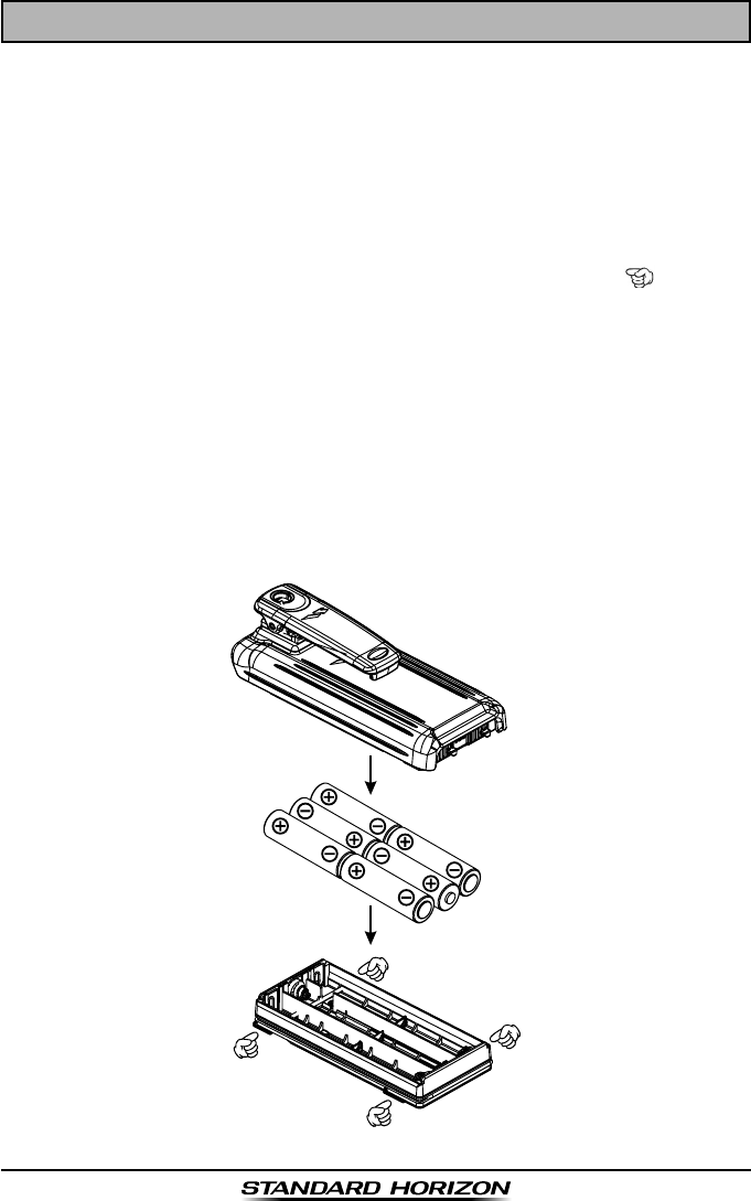
10.1 FBA-42 ALKALINE BATTERY TRAY
FBA-42 is a battery tray that holds six AA size Alkaline batteries and is used
with the HX407 transceiver. When the FBA-42 is installed into the HX407 the
radio can withstand immersion in water up to 1.5 m (about 5Ft) for 30 min-
utes.
1. On the FBA-42, remove the battery tray cover. Due to the battery tray
water proof characteristics, it may be difcult to remove the battery tray
cover, put a coin to the edge of the battery compartment ( ) then pry
open the battery tray cover.
2. Slide the six AA size Alkaline batteries into the FBA-42 Battery Tray with
the Negative (–) side of the batteries touching the spring connections in-
side the FBA-42 Batter y Tray.
3. Attach the battery cover to the FBA-42 Battery Tray while being careful
so that o-ring is not twisted.
4. Insert the FBA-42 Battery Tray into the battery compartment on the back
of the HX407 transceiver, then push the bottom side of the FBA-42 Bat-
tery Tray until the Battery Tray locks with the Battery Pack Latch.
Application for FCC / IC
FCC ID: K6630394X20
IC: 511B-30394X20

Page 25HX407
11. SPECIFICATIONS
Performance specications are nominal, unless otherwise indicated, and are
subject to change without notice.
11.1 GENERAL
Frequency Ranges: 400.000 MHz to 470.000 MHz
Channel Spacing: 25 kHz / 12.5 kHz
Frequency Stability: ±2.5 ppm
Emission Type: 16K0G3E / 11K0G3E
Antenna Impedance: 50
Supply Voltage: 7.4V DC, Negative Ground
(Battery Terminal)
Operating Temperature: -22 °F to +140 °F (-30 °C to +60 °C)
Battery Type and capacity: Lithium-Ion, 2300 mAh (Rated)
2400 mAh (Typ)
Waterproof Rating: JIS-8 / IPX8
(1.5 m (about 5 Ft) for 30 minutes)
11.2 TRANSMITTER
RF Power Output: 5 W / 1 W (@7.4 V )
Maximum Deviation: ±5.0 kHz (Wide) / ±2.5 kHz (Narrow)
Hum and Noise Ratio: More than 40 dB
Spurious Emission: Less than 0.25 uW
11.3 RECEIVER
Adjacent Channel Selectivity: More than 70 dB (Wide),
More than 60 dB (Narrow)
Intermodulation: More than 68 dB
Spurious Response Rejection: More than 70 dB
Hum and Noise Ratio: More than 40 dB
Max imum Audio Output Power: 700 mW @16 for 10 % THD (@7.4 V)
AF Output (External SP): 300 mW @8 for 10 % THD (@7.4 V)
Spurious Emission: Less than 2 nW
Measured in accordance with TIA/EIA-603.
Application for FCC / IC
FCC ID: K6630394X20
IC: 511B-30394X20

HX407Page 26
FCC AND CANADA RADIO LICENSE INFORMATION
Standard Horizon radios comply with the Federal Communication Commis-
sion (FCC) and Industry-Canada requirements that regulate the Maritime
Radio Service.
MARITIME STATION LICENSE
An FCC ship station license is no longer required for any vessel traveling in
U.S. waters which uses a UHF marine radio, RADAR or EPIRB, and which is
not required to carry radio equipment. However, any vessel required to carry
a marine radio on an international voyage, carrying a HF single side band
radiotelephone or marine satellite terminal. FCC license forms, including ap-
plications for ship (605) and land station licenses can be downloaded via the
Internet at www.fcc.gov/Forms/Form605/605.html. To obtain a form from the
FCC, call (888) 225-5322.
MARINE RADIO CALL SIGN
Currently the FCC does not require recreational boaters to have a Ship Ra-
dio Station License. The USCG recommends the boats registration number
and the state to be used.
CANADIAN SHIP STATION LICENSING
You may need a license when traveling in Canada. If you do need a license
contact their nearest eld ofce or regional ofce or write:
Industry Canada
Radio Regulatory Branch
Attn: DOSP
300 Slater Street
Ottawa, Ontario
Canada, KIA 0C8
Application for FCC / IC
FCC ID: K6630394X20
IC: 511B-30394X20

Page 27HX407
THIS DEVICE COMPLIES WITH PART 15 OF THE FCC RULES. OPERATION IS
SUBJECT TO THE FOLLOWING TWO CONDITIONS: (1) THIS DEVICE MAY NOT
CAUSE HARMFUL INTERFERENCE, AND (2) THIS DEVICE MUST ACCEPT ANY
INTERFERENCE RECEIVED, INCLUDING INTERFERENCE THAT MAY CAUSE
UNDESIRED OPERATION.
Changes or modications to this device not expressly approved by YAESU U.S.A.
could void the User’s authorization to operate this device.
This device complies with Industry Canada license-exempt RSS standard(s).
Operation is subject to the following two conditions: (1) this device may not cause
interference, and (2) this device must accept any interference, including interference
that may cause undesired operation of the device.
Le présent appareil est conforme aux CNR d’Industrie Canada applicables aux
appareils radio exempts de licence. L’exploitation est autorisée aux deux conditions
suivantes : (1) l’appareil ne doit pas produire de brouillage, et (2) l’utilisateur de
l’appareil doit accepter tout brouillage radioélectrique subi, même si le brouillage
est susceptible d’en compromettre le fonctionnement.
Under Industry Canada regulations, this radio transmitter may only operate using
an antenna of a type and maximum (or lesser) gain approved for the transmitter by
Industry Canada. To reduce potential radio interference to other users, the antenna
type and its gain should be so chosen that the equivalent isotropically radiated power
(e.i.r.p.) is not more than that necessary for successful communication.
Conformément à la réglementation d’Industrie Canada, le présent émetteur radio
peut fonctionner avec une antenne d’un type et d’un gain maximal (ou inférieur)
approuvé pour l’émetteur par Industrie Canada. Dans le but de réduire les risques
de brouillage radioélectrique à l’intention des autres utilisateurs, il faut choisir le
type d’antenne et son gain de sorte que la puissance isotrope rayonnée quivalente
(p.i.r.e.) ne dépassepas l’intensité nécessaire à l’établissement d’une communication
satisfaisante.
This radio transmitter (identify the device by certication number, or model number
if Category II) has been approved by Industry Canada to operate with the antenna
types listed below with the maximum permissible gain and required antenna
impedance for each antenna type indicated. Antenna types not included in this list,
having a gain greater than the maximum gain indicated for that type, are strictly
prohibited for use with this device.
Le présent émetteur radio (identier le dispositif par son numéro de certication ou
son numéro de modèle s’il fait partie du matériel de catégorie I) a été approuvé par
Industrie Canada pour fonctionner avec les types d’antenne énumérés ci-dessous
et ayant un gain admissible maximal et l’impédance requise pour chaque type
d’antenne. Les types d’antenne non inclus dans cette liste, ou dont le gain est
supérieur au gain maximal indiqué, sont strictement interdits pour l’exploitation de
l’émetteur. l’établissement d’une communication satisfaisante.
Application for FCC / IC
FCC ID: K6630394X20
IC: 511B-30394X20

Copyright 2015
YAESU MUSEN CO., LTD.
All rights reserved.
No portion of this manual
may be reproduced
without the permission of
YAESU MUSEN CO., LTD.
Printed in Japan
YAESU USA
6125 Phyllis Drive, Cypress, CA 90630
Application for FCC / IC
FCC ID: K6630394X20
IC: 511B-30394X20