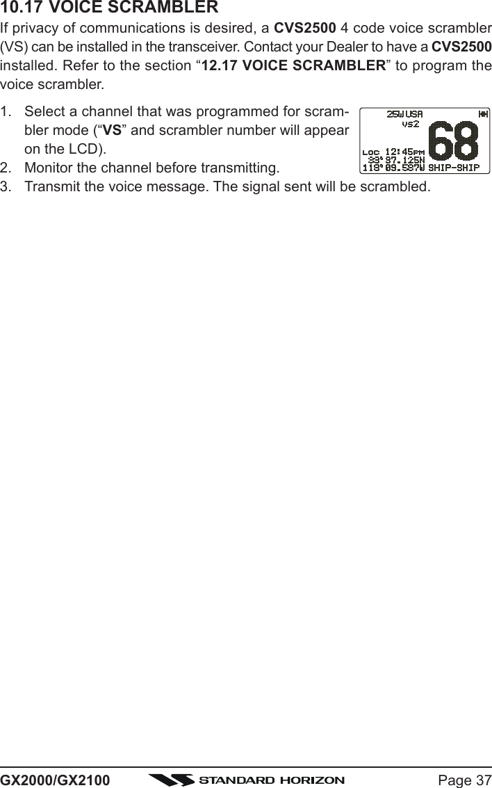
Yaesu Musen 30443X3D MOBILE MARINE TRANSCEIVER User Manual GX2000S GX2100S Owner s Manual pmd
Yaesu Musen Co., Ltd. MOBILE MARINE TRANSCEIVER GX2000S GX2100S Owner s Manual pmd
Contents
- 1. Users Manual
- 2. Operating Manual 1
- 3. Operating Manual 2
Users Manual
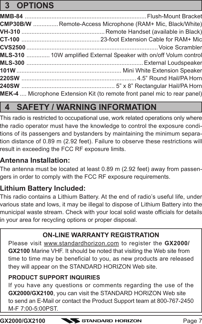
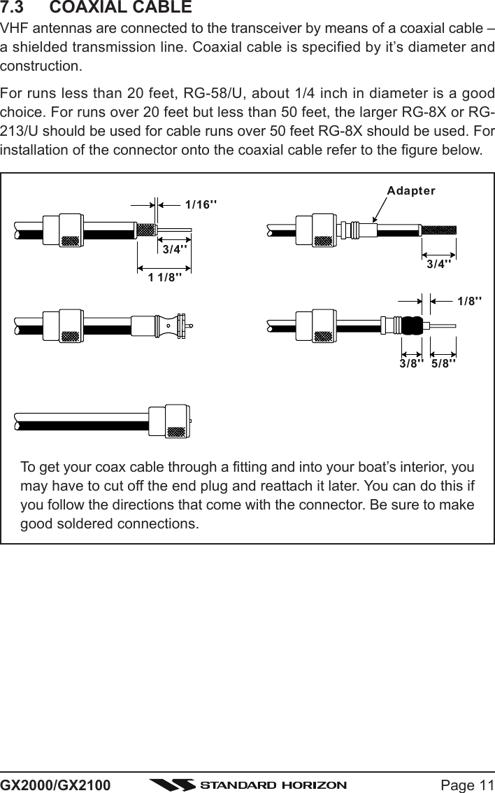
![GX2000/GX2100Page 2QUICK REFERENCE GUIDE IYou can do the basic operation in numerical order of the illustration below.h[PTT] SWITCHSpeak into themicrophone in anormal voice levelwhile pressing thisswitch.d[TTTTT] / [SSSSS] KEYSelects the operatingchannel.f[H/L] BUTTONWhen pressed,toggles the transmitpower between High(25W) and Low (1W).e[SQL] KNOBMove this controlclockwise to squelchor counter clockwiseun-squelch the radio.c[PWR/VOL] KNOBPress and hold this knob until the LCDturns on, and adjust the audio level.d[CH] KNOBSelects the operating channel.g[16/9] BUTTONyPress to recall chan-nel 16.yPress and hold torecall channel 9.g[16/9] BUTTONyPress to recallchannel 16.yPress and hold torecall channel 9.MICROPHON](https://usermanual.wiki/Yaesu-Musen/30443X3D.Users-Manual/User-Guide-1203519-Page-2.png)
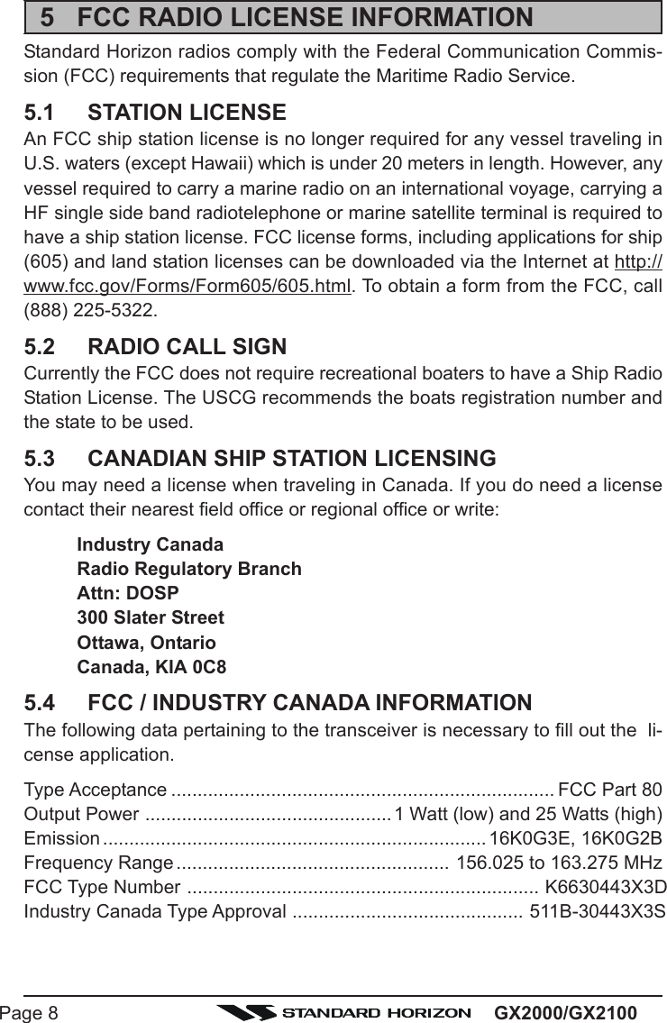
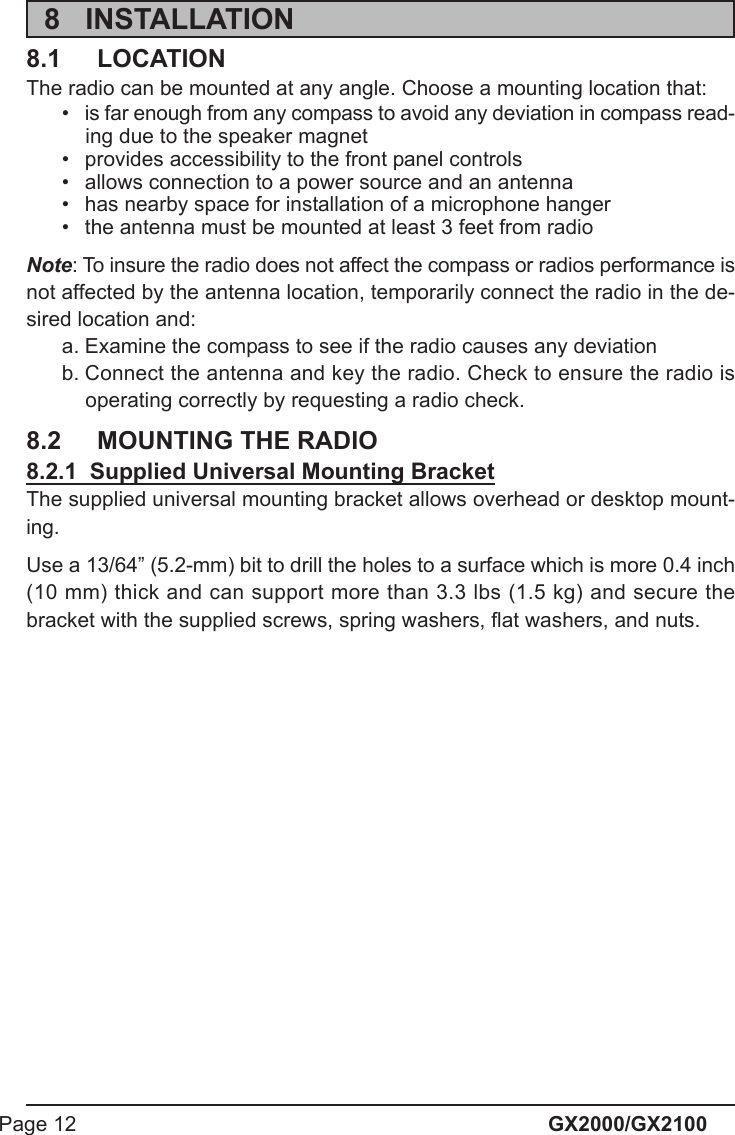
![Page 3GX2000/GX2100[DISTRESS] BUTTONNote: for this key tooperate a MMSI mustbe programmed.Lift the red cover,press the Distress but-ton once, then pressand hold until the ra-dio alarms.QUICK REFERENCE GUIDE II[CALL/MENU] BUTTONyPress to access the“DSC MENU”.yPress and hold toaccess the “SETUPMENU”.[CH] KNOBySelect the operatingchannel.ySelect the item inthe “SETUP MENU”and “DSC MENU”.yWhen the “SETUPMENU” or “DSCMENU” is selected,pressing this knobsaves a selection.[CLR/WX] BUTTONyPress to cancel themenu selection.yPress and hold torecall the last-usedNOAA WeatherChannel.[PROGRAMMABLE] KEYThese three keysfunctions can be cus-tomized by the SetupMenu mode.The factory defaultsare [PA/FOG], [IC],and [SCAN] key.[AIS] BUTTONPress to change thedisplay to AIS (Auto-matic IdentificationSystem) mode](https://usermanual.wiki/Yaesu-Musen/30443X3D.Users-Manual/User-Guide-1203519-Page-3.png)
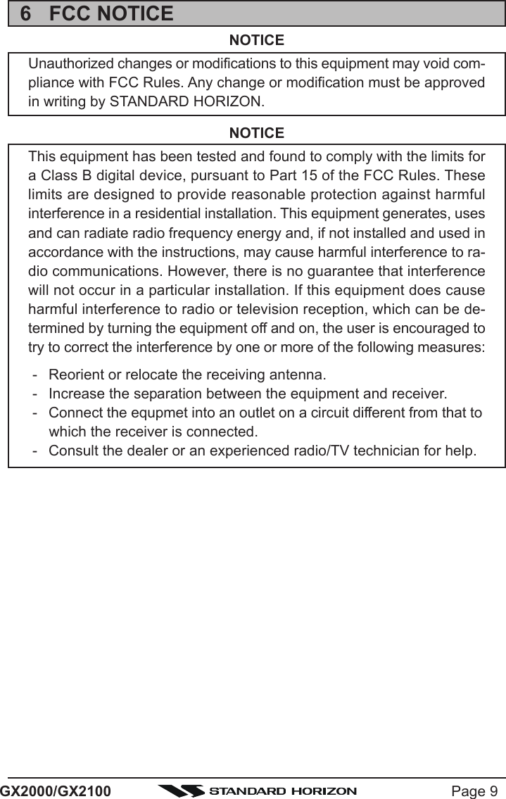
![GX2000/GX2100Page 61 GENERAL INFORMATION1.1 INTRODUCTIONThe STANDARD HORIZON GX2000/2100 is a VHF/FM Marine Transceiverdesigned for use in the frequency range of 156.025 to 163.275 MHz. TheGX2000/2100 can be operated from 11 to 16 VDC and has a switchable RFoutput power of 1 watt or 25 watts.The GX2100 is equipped with the AIS (Automatic Identification System) re-ceiver and its display program which enables to identify and avoid other largevessels nearby your vessel. The GX2100 is equipped with the display pro-gram of the AIS too. Threrfore, the GX2000 also enables to identify and avoidother large vessels nearby your vessel, if the AIS receiver (not supply) iscommected.The GX2000/GX2100 is capable of DSC (Digital Selective Calling) Class Doperation and an Enhanced second station RAM+ mic (CMP30 remote-con-trol speaker/microphone with display) or VH-310 Handset. Class D operationallows continuous receiving of Digital Selective Calling functions on channel70 even if the radio is receiving a call.The GX2000/GX2100 operates on all currently-allocated marine channelswhich are switchable for use with USA, International, or Canadian regulations.It has an emergency channel 16 which can be immediately selected from anychannel by pressing the red [16/9] key. NOAA Weather channels can also beaccessed immediately by Press and holding the [CLR(WX)] key with channelselection.Other features of the GX2000/GX2100 include: 30W PA/Fog, multi-stationintercom, scanning, priority scanning, submersible speaker mic, high and lowvoltage warning, and GPS repeatability.2 PACKING LISTWhen the package containing the transceiver is first opened, please check itfor the following contents:yGX2000 or GX2100 TransceiveryMounting Bracket and attaching hardwareyOwner’s ManualyWarning StickeryPower Cord](https://usermanual.wiki/Yaesu-Musen/30443X3D.Users-Manual/User-Guide-1203519-Page-6.png)
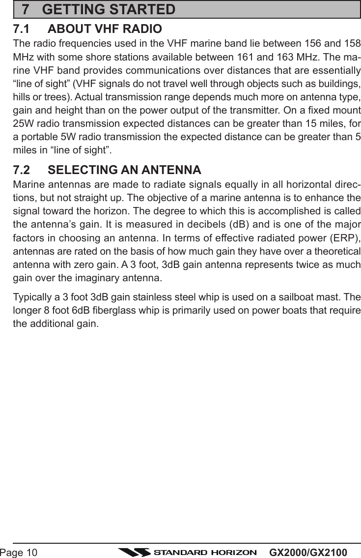
![GX2000/GX2100Page 16OFFSET TIME TABLE8.5 CHECKING GPS CONNECTIONSAfter connections have been made between theGX2000/GX2100 and the GPS, a small satellite iconwill appear on the top right corner of the LCD displayanddisplays your current location (Latitude/Longitude) onthe display.NOTEIf there is a problem with the NMEA input from a GPS, the GPS icon willblink continuously until the connection is corrected.8.6 CHANGING THE GPS TIMEFrom the Factory the GX2000/GX2100 shows GPS satellite time or UTCtime when a optional GPS is connected. A time offset is needed to show thelocal time in your area.1. Press and hold down the [CALL(MENU)] key until“SETUP MENUSETUP MENUSETUP MENUSETUP MENUSETUP MENU” appears, then select “GENERALGENERALGENERALGENERALGENERALSETUPSETUPSETUPSETUPSETUP” with the CH knob.2. Press the CH knob, then select “TIME OFFSETTIME OFFSETTIME OFFSETTIME OFFSETTIME OFFSET” withthe CH knob.3. Press the CH knob, then turn the CH knob to selecttime offset from UTC. See illustration below to findyour offset time from UTC. If “00:0000:0000:0000:0000:00” is assigned,the time is the same as UTC (Universal Time Coor-dinated or GMT Greenwich Mean Time).4. Press the CH knob to store the time offset.5. Press the [CLR(WX)] key several times to return toradio operation.](https://usermanual.wiki/Yaesu-Musen/30443X3D.Users-Manual/User-Guide-1203519-Page-16.png)
![Page 17GX2000/GX21008.7 CHANGING THE TIME LOCATIONSet the radio show UTC time or local time with the offset inputted in section 8.6CHANGING THE GPS TIME.1. Press and hold down the [CALL(MENU)] key until“SETUP MENUSETUP MENUSETUP MENUSETUP MENUSETUP MENU” appears, then select “GENERALGENERALGENERALGENERALGENERALSETUPSETUPSETUPSETUPSETUP” with the CH knob.2. Press the CH knob, then select “TIME DISPLAYTIME DISPLAYTIME DISPLAYTIME DISPLAYTIME DISPLAY” withthe CH knob.3. Press the CH knob.4. Turn the CH knob to select “UTCUTCUTCUTCUTC” or “LOCALLOCALLOCALLOCALLOCAL”.5. Press the CH knob to store the selected setting.6. Press the [CLR(WX)] key several times to return toradio operation.8.8 CHANGING COG TO TRUE OR MAGNETICAllows the GPS Course Over Ground to be selected to show in True or Mag-netic. Factory default is True however following the steps below the COG canbe changed to Magnetic.1. Press and hold down the [CALL(MENU)] key until“SETUP MENUSETUP MENUSETUP MENUSETUP MENUSETUP MENU” appears, then select “GENERALGENERALGENERALGENERALGENERALSETUPSETUPSETUPSETUPSETUP” with the CH knob.2. Press the CH knob, then select “MAGNETICMAGNETICMAGNETICMAGNETICMAGNETIC” withthe CH knob.3. Press the CH knob.4. Turn the CH knob to select “MAGNETICMAGNETICMAGNETICMAGNETICMAGNETIC” or “TRUETRUETRUETRUETRUE”.5. Press the CH knob to store the selected setting.6. Press the [CLR(WX)] key several times to return toradio operation.](https://usermanual.wiki/Yaesu-Musen/30443X3D.Users-Manual/User-Guide-1203519-Page-17.png)
![Page 19GX2000/GX2100Remote Mic or External Speaker SelectionBy default the RAM+ or VH-310 Handset internal speaker is turned on, how-ever using the RAM+ mic (or VH-310 Handset) this speaker can be turned offso the external speaker can be used.RAM+ mic procedure1. Press and hold the [CALL(ENT)] key.2. Press the [S] or [T] key to select “RADIO SETUPRADIO SETUPRADIO SETUPRADIO SETUPRADIO SETUP.”3. Press the [CALL(ENT)] key.4. Press the [T] key to until “EXT SPKEXT SPKEXT SPKEXT SPKEXT SPK” is shown and press the[CALL(ENT)] key.5. Press the [S] or [T] key to select “oFoFoFoFoF” (External speakeroff) or “ononononon” (External speaker on).6. Press the [CALL(ENT)] key to save the selection.7. Press the [16/9] key to exit this mode.VH-310 Procedure1. Press and hold the [CALL(MENU)] key.2. Press the [S] or [T] key to select “RADIO SETUPRADIO SETUPRADIO SETUPRADIO SETUPRADIO SETUP.”3. Press the [ENT] key4. Press the [T] key to until “EXT SPKEXT SPKEXT SPKEXT SPKEXT SPK” is shown and press the[ENT] key.5. Press the [S] or [T] key to select “oFoFoFoFoF” (External speakeroff) or “ononononon” (External speaker on).6. Press the [ENT] key to save the selection.7. Press the [16/9] key to exit this mode.](https://usermanual.wiki/Yaesu-Musen/30443X3D.Users-Manual/User-Guide-1203519-Page-19.png)
![GX2000/GX2100Page 209 CONTROLS AND INDICATORSNOTEThis section defines each control of the transceiver. See illustration atthe next page for location of controls. For detailed operating instructionsrefer to chapter 10 of this manual.9.1 CONTROLS AND CONNECTIONSCH KnobRotary knob used to select channels and to choose menu items (such asthe DSC menu, Radio Setup and DSC Setup menu). The [UP(S)] /[DOWN(T)] keys on the microphone can also be used to select channelsand menu items.SECONDARY USEyPress this knob to enter a selection the “SETUP MENU” or “DSC MENU”.yWhile holding down the [SCAN] key and turning this knob, you can con-firm memory channels for scanning.yAdjust the PA output level while in PA/FOG mode.PWR/VOL Knob (Power Switch / Volume Control)Turns the transceiver on and off as well as adjusts the audio volume.To turn the transceiver on, press and hold this knob until the LCD turns on.When the power is turned on, the transceiver is set to the last selectedchannel. Clockwise rotation of this knob increases the audio volume level.To turn the transceiver off, press and hold this knob until the LCD turns off.SECONDARY USEWhen in PA or Fog mode, controls the listen back volume.SQL Knob (Squelch Control)Adjusting this control clockwise, sets the point at which random noise onthe channel does not activate the audio circuits but a received signal does.This point is called the squelch threshold. Further adjustment of the squelchcontrol will degrade reception of wanted transmissions.](https://usermanual.wiki/Yaesu-Musen/30443X3D.Users-Manual/User-Guide-1203519-Page-20.png)
![GX2000/GX2100Page 22Programmable KeyThese three keys functions can be customized by the Setup Menu mode.When press one of these key briefly, the key functions will appear at theLCD bottom. The factory defaults are shown below.[Left] Key: [PA] functionPress this key to activate the 30W PA or FOG Horn Function. Refer tosection “10.15 PA/FOG OPERATION” for details.[Center] Key: [IC] functionPress this key to activate the intercom operation (operate between ra-dio and option mic or handset), when the optional CMP30 (RAM3) Re-mote Station Microphone or VH-310 Handset is connected. Refer tosection “10.16 INTERCOM OPERATION” for details.[Right] Key: [SCAN] functionPress this key to start and stop the scanning of programmed channels.Refer to section “10.13 SCANNING” for details.SECONDARY USEPress and hold this key to memorizes the selected channel into thetransceivers scan memory for scanning (“MEM” appears on the dis-play). When press and hold again, it DELETES the channel from thescan memory (“MEM” disappears from the display).[AIS] KeyPress the [AIS] key to display the AIS (Automatic Identification System)information on the display. Refer to section “10.14 AIS OPERATION” fordetails.[CLR(WX)] KeyPress the [CLR(WX)] key briefly to cancel a selection the “Setup Menu”and “DSC Menu”.Press and hold the [CLR(WX)] key to recall the previously selected NOAAweather channel from any channel. Press and hold the [CLR(WX)] keyagain reverts to the previous selected working channel.SECONDARY USEPress the [CLR(WX)] key while pressing and holding the [16/9] key to switchthe channel group between “USA”, “International”, and “Canadian”.[CALL(MENU)] KeyPress the [CALL(MENU)] key to access the “DSC MENU”.SECONDARY USEPress and hold the [CALL(MENU)] key to access the “SETUP MENU”.](https://usermanual.wiki/Yaesu-Musen/30443X3D.Users-Manual/User-Guide-1203519-Page-22.png)
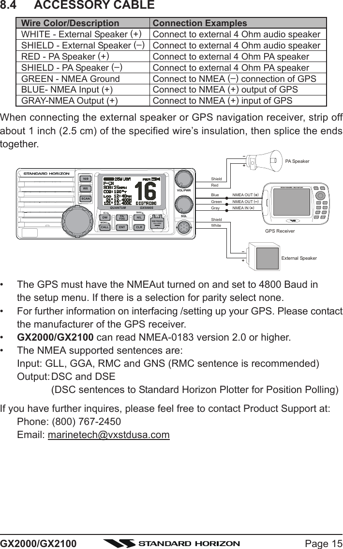
![Page 23GX2000/GX2100[H/L] KeyPress the [H/L(NAV)] key to toggle between 25 W (High) and 1 W (Low)power. When the TX output power is set to “Low” while the transceiver ison channel 13 or 67, the output power will temporarily switch from “Low” to“High” power until the PTT is released. The [H/L] key does not function ontransmit inhibited and low power only channels.[16/9] KeyPress the [16/9] key briefly to recall channel 16 from any channel location.Press and hold the [CLR(WX)] key to recall channel 9. Pressing the [16/9]key again reverts to the previous selected working channel.SECONDARY USEPress the [CLR(WX)] key while pressing and holding the [16/9] key to switchthe channel group between “USA”, “International”, and “Canadian”.[DISTRESS] KeyUsed to send a DSC Distress Call. To send the distress call refer to section“11.3.1 Transmitting a DSC Distress Call.”ANT Jack (Antenna Jack)Connects an antenna to the transceiver. Use a marine VHF antenna withan impedance of 50 ohms.GND Terminal (Ground Terminal)Connects the GX2000/GX2100 to a good ground, for safety and opti-mum performance.Install only the supplied screw or similar size (M3x6, Stainless Steel) screw.Accessory Connection Cable (Green, Blue, Gray, & Brown)Connects the GX2000/GX2100 to a GPS receiver and AIS receiver.PA Speaker Connection Cable (Red & Shield)Connects the GX2000/GX2100 to a optional PA speaker. See section“3 OPTIONS” for a list of optional STANDARD HORIZON Speakers.External Speaker Connection Cable (White & Shield) an external speaker. See section “3 OPTIONS” for a list of optional STAN-DARD HORIZON Speakers.DC Input CableConnects the radio to a DC power supply capable of delivering 12 to 16VDC.](https://usermanual.wiki/Yaesu-Musen/30443X3D.Users-Manual/User-Guide-1203519-Page-23.png)
![GX2000/GX2100Page 24RAM Connector (Remote Station Microphone Connector)Connects the GX2000/GX2100 to the CMP30 (RAM3) Remote StationMicrophone or the VH-310 Handset. Refer to section “13 CMP30 (RAM3)OPERATION” or “14 VH-310 HANDSET OPERATION” for detailsPTT Switch (Push-To-Talk Switch)Keys the transmitter when the transceiver is in Radio mode. If the trans-ceiver is in the Intercom Operation mode (between the Remote StationMicrophone and the Radio), it activates the GX2000/GX2100 micro-phone for voice communications.MicrophoneTransmits the voice message with reduction of background noise, usingClear Voice Noise Reduction Technology.Microphone SpeakerThe same audio heard through internal radio speaker is heard throughmicrophone speaker.[UP(S)] / [DOWN(T)] KeysThe [UP(S)] and [DOWN(T)] on the microphone function the same as theCH knob on the front panel of the transceiver.[16/9] KeyPressing the [16/9] key immediately recalls channel 16 from any location.Press and hold the [16/9] key to recall channel 9. Pressing the [16/9] keyagain will revert the radio to the previous selected channel.](https://usermanual.wiki/Yaesu-Musen/30443X3D.Users-Manual/User-Guide-1203519-Page-24.png)
![GX2000/GX2100Page 2610.4 TRANSMIT TIME - OUT TIMER (TOT)When the PTT switch on the microphone is held down, transmit time is limited to5 minutes. This limits unintentional transmissions due to a stuck microphone.About 10 seconds before automatic transmitter shutdown, a warning beep will beheard from the speaker(s). The transceiver will automatically go to receive mode,even if the PTT switch is continually held down. Before transmitting again, thePTT switch must first be released and then pressed again.10.5 SIMPLEX/DUPLEX CHANNEL USERefer to the VHF MARINE CHANNEL CHART (page ) for instructions onuse of simplex and duplex channels.NOTEAll channels are factory-programmed in accordance with FCC (USA),Industry Canada (Canada), and International regulations. Mode of op-eration cannot be altered from simplex to duplex or vice-versa.10.6 USA, CANADA, AND INTERNATIONAL MODE1. To change the Channel Group, hold the [16/9] key and press the [WX] key.The mode changes from USA to International to Canadian with each pressof the [CLR(WX)] key.2. “USA” will be displayed on the LCD for USA mode, “INTL” will be displayedfor International mode, and “CAN” will be displayed for Canadian mode.3. Refer to the VHF MARINE CHANNEL CHART (page ) for allocated chan-nels in each mode.10.7 NOAA WEATHER CHANNELS1. To receive a NOAA weather channel, press and hold the [CLR(WX)] keyfor 2 seconds from any channel. The transceiver will go to the last selectedweather channel.2. Turn the CH knob on the radio or [UP(S)] / [DOWN(T)] keys on the micro-phone to select a different NOAA weather channel.3. To exit from the NOAA weather channels, press the [CLR(WX)] key. Thetransceiver returns to the channel it was on prior to a weather channel.10.7.1 NOAA Weather AlertIn the event of extreme weather disturbances, such as storms and hurricanes,the NOAA (National Oceanic and Atmospheric Administration) sends a weatheralert accompanied by a 1050 Hz tone and subsequent weather report on oneof the NOAA weather channels. When the Weather Alert feature is enabled(see section “12.11 WX ALERT”), the transceiver is capable of receiving thisalert if the following is performed:](https://usermanual.wiki/Yaesu-Musen/30443X3D.Users-Manual/User-Guide-1203519-Page-26.png)
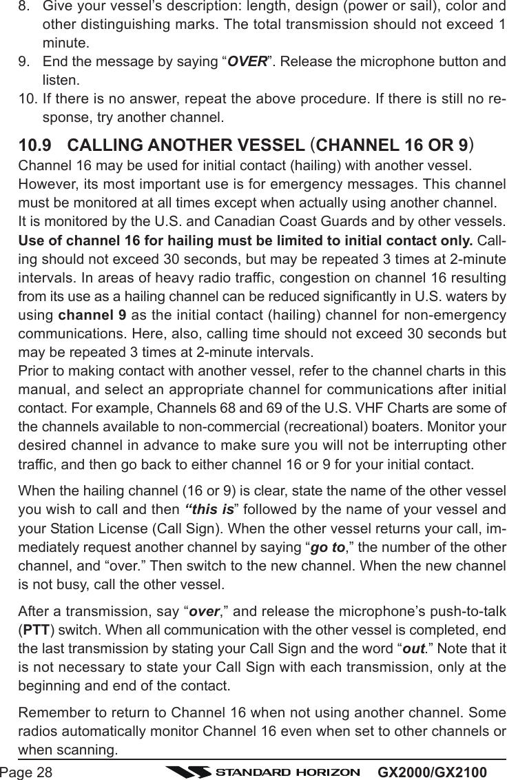
![Page 27GX2000/GX21001. Program NOAA weather channels into the transceiver’s memory for scan-ning. Follow the same procedure as for regular channels under section“10.13.2 Memory Scanning (M-SCAN).”2. Press the [SCAN] key once to start memory scanning.3. The programmed NOAA weather channels will be scanned along with theregular-programmed channels. However, scanning will not stop on a nor-mal weather broadcast unless a NOAA alert is received.4. When an alert is received on a NOAA weather channel, scanning will stop andthe transceiver will emit a loud beep to alert the user of a NOAA broadcast.5. Press the [CLR(WX)] key to stop the alert tone and receive the weatherreport.NOTEIf the [CLR(WX)] key is not pressed the alert tone will be emitted for 5minutes and then the weather report will be received.NOTEThe Weather Alert feature is also engaged while the transceiver is re-ceiving on one of the NOAA weather channels.10.7.2 NOAA Weather Alert TestingNOAA tests the alert system ever Wednesday between 11AM and 1PM. To testthe GX2000/GX2100’s NOAA Weather feature, on Wednesday between11AM and 1PM, setup as in section “10.7.1 NOAA Weather Alert” and confirmthe alert is heard.10.8 EMERGENCY (CHANNEL 16 USE)Channel 16 is known as the Hail and Distress Channel. An emergency may bedefined as a threat to life or property. In such instances, be sure the transceiveris on and set to CHANNEL 16. Then use the following procedure:1. Press the microphone push-to-talk switch and say “Mayday, Mayday, May-day. This is , , ” (your vessel’s name).2. Then repeat once: “Mayday, ” (your vessel’s name).3. Now report your position in latitude/longitude, or by giving a true or mag-netic bearing (state which) to a well-known landmark such as a navigationaid or geographic feature such as an island or harbor entry.4. Explain the nature of your distress (sinking, collision, aground, fire, heartattack, life-threatening injury, etc.).5. State the kind of assistance your desire (pumps, medical aid, etc.).6. Report the number of persons aboard and condition of any injured.7. Estimate the present seaworthiness and condition of your vessel.](https://usermanual.wiki/Yaesu-Musen/30443X3D.Users-Manual/User-Guide-1203519-Page-27.png)
![Page 29GX2000/GX210010.10 MAKING TELEPHONE CALLSTo make a radiotelephone call, use a channel designated for this purpose, Thefastest way to learn which channels are used for radiotelephone traffic is toask at a local marina. Channels available for such traffic are designated Pub-lic Correspondence channels on the channel charts in this manual. Someexamples for USA use are Channels 24, 25, 26, 27, 28, 84, 85, 86, and 87.Call the marine operator and identify yourself by your vessel’s name, The marineoperator will then ask you how you will pay for the call (telephone credit card,collect, etc.) and then link your radio transmission to the telephone lines.The marine telephone company managing the VHF channel you are usingmay charge a link-up fee in addition to the cost of the call.10.11 OPERATING ON CHANNELS 13 AND 67Channel 13 is used at docks and bridges and by vessels maneuvering in port.Messages on this channel must concern navigation only, such as meeting andpassing in restricted waters.Channel 67 is used for navigational traffic between vessels.By regulation, power is normally limited to 1 Watt on these channels. Yourradio is programmed to automatically reduce power to this limit on these chan-nels. However, in certain situations it may be necessary to temporarily use ahigher power. See page 23 (H/L key) for means to temporarily override thelow-power limit on these two channels.10.12 DUAL WATCH (TO CHANNEL 16)1. Adjust the SQL knob until the background noise disappears.2. Select the channel you wish to dual watch to CH16.3. Press the [DW(IC)] key. The display will scan between CH16 and the chan-nel that was selected in step 2.If a transmission is received on the channel selectedin step 2, the GX2000/GX2100 will dual watch toCH16.4. To stop Dual Watch press the [DW(IC)] key again.](https://usermanual.wiki/Yaesu-Musen/30443X3D.Users-Manual/User-Guide-1203519-Page-29.png)
![GX2000/GX2100Page 3010.13 SCANNINGAllows the user to select the scan type from Memory scan or Priority scan.“Memory scan” scans the channels that were programmed into memory. “Pri-ority scan” scans the channels programmed in memory with the priority chan-nel.10.13.1 Selecting the Scan Type1. Press and hold down the [CALL(MENU)] key until“Setup MenuSetup MenuSetup MenuSetup MenuSetup Menu” appears.2. Press the CH knob, then select “CH Function SetupCH Function SetupCH Function SetupCH Function SetupCH Function Setup”with the CH knob.3. Press the CH knob, then select “SCAN TypeSCAN TypeSCAN TypeSCAN TypeSCAN Type” withthe CH knob.4. Press the CH knob.5. Turn the CH knob to select “Priority SCANPriority SCANPriority SCANPriority SCANPriority SCAN” or“Memory SCANMemory SCANMemory SCANMemory SCANMemory SCAN.”6. Press the CH knob to store the selected setting.7. Press the [CLR(WX)] key several times to return toradio operation.10.13.2 Memory Scanning (M-SCAN)1. Adjust the SQL knob until background noise disappears.2. Select a desired channel to be scanned using the CH knob.3. Press the one of the Programmable key momen-tarily to indicate these function on the LCD, thenpress and hold the [SCAN] key until “MEM” appearson the LCD which indicates the channel has beenprogrammed into the transceivers memory.4. Repeat steps 2 and 3 for all the desired channels to be scanned.5. To DELETE a channel from the transceiver’s memory, select the channelthen press and hold the [SCAN] key until “MEM” disappears from the LCD.6. To start scanning, press the [SCAN] key momen-tarily. “M-SCANM-SCANM-SCANM-SCANM-SCAN” appears on the LCD. Scanning willproceed from the lowest to the highest programmedchannel number and will stop on a channel when atransmission is received.7. The channel number will blink during reception.8. To stop scanning, press the [16/9] or [CLR(WX)] key.](https://usermanual.wiki/Yaesu-Musen/30443X3D.Users-Manual/User-Guide-1203519-Page-30.png)
![Page 31GX2000/GX210010.13.3 Priority Scanning (P-SCAN)In the default setting, Channel 16 is set as the priority channel. You may changethe priority channel to the desired channel from the Channel 16 by the RadioSetup Mode, refer to section “12.7 PRIORITY CHANNEL SET.”1. Adjust the SQL knob until background noise disappears.2. Select a desired channel to be scanned using the CH knob.3. Press the one of the Programmable key momen-tarily to indicate these function on the LCD, thenpress and hold the [SCAN] key for one second,“MEM” will appear on the display which indicatesthe channel has been programmed into the transceivers memory.4. Repeat steps 2 and 3 for all the desired channels to be scanned.5. To DELETE a channel from the transceiver’s memory, select the channelthen press and hold the [SCAN] key until “MEM” disappears from the LCD.6. To start priority scanning, press the [SCAN] keymomentarily. “P-SCANP-SCANP-SCANP-SCANP-SCAN” appears on the LCD. Scan-ning will proceed between the memorized channelsand the priority channel. The priority channel will bescanned after each programmed channel.7. To stop scanning, press the [16/9] or [WX] key.You may change the scan resume time in the Radio Setup Mode, refer tosection “12.9 SCAN RESUME TIME.”](https://usermanual.wiki/Yaesu-Musen/30443X3D.Users-Manual/User-Guide-1203519-Page-31.png)
![GX2000/GX2100Page 3210.14 AIS OPERATIONThe GX2000 is equipped with an AIS (AUTOMATIC IDENTIFICATION SYSTEM) re-ceiver and can display the its received data on the display. Therefore, youidentify and avoid other large vessels nearby your vessel.The GX2100 also can display the received data on the display if you connectthe AIS receiver (not prepared) to the Accessory Connection Cable.1. Press the [AIS] key to appear the AIS screen. The LCD displays apparentvessel which equipped the AIS.2. Press the one of the Programmable key momentarily to indicate thesefunction on the LCD, then press the [LIST] key to appear the MMSI num-ber of the vessels which displayed on the LCD.3. Turn the CH knob to select the MMIS number, then press the [INFO] key toshow more information of that station.4. If you wish to contact (Individual Call) that station, press the [CALL] key,then turn the CH knob to select the operating channel you want to commu-nicate on and press the CH knob.5. Press the CH knob again to transmit the individual DSC signal. See page?? for details regarding the “Individual Call” operation.6. Press the [QUIT] key to return to radio screen.](https://usermanual.wiki/Yaesu-Musen/30443X3D.Users-Manual/User-Guide-1203519-Page-32.png)
![Page 33GX2000/GX210010.15 PA/FOG OPERATIONThe GX2000/GX2100 has a 30W Hailer built-in and can be used with any4 Ohm PA Horns. Standard Horizon offers a small and a large PA horn calledthe 220SW and 240SW. When in Hail mode the PA speaker Listen’s Back(acts as a microphone and sends sound to the front panel speaker and thespeaker mic) through the PA horn speaker which provides two-way communi-cations through the PA horn speaker.NOTEWhen in PA or FOG mode the GX2000/GX2100 will receive on thelast selected VHF channel before entering into the PA or FOG modeand receive DSC calls.PA HAIL mode:PA HAIL mode allows the transceiver to be used as a power hailer when anoptional STANDARD HORIZON 220SW or 240SW HAIL/PA speaker is in-stalled. The Hail mode has a listen-back feature which provides two waycommunication through the HAIL/PA speaker.FOG HORN mode:Automatic signaling is transmitted through the HAIL/PA speaker. When theFog horn, Bells or Whistle signal is not being outputted the GX2000/GX2100 listens back through the connected PA Horn speaker.10.15.1 Operating the PA HAIL mode1. Press the [PA] key, then select “PAPAPAPAPA” with the CH knob.2. Press the CH knob.3. Press the PTT switch to speak through the HAIL/PAspeaker.Turn the CH knob to control the AF output level. TheAF output level can be set from 0 to 30 watts.4. When the fog signal is not outputted, turn the PWR/VOL knob to adjust listen back volume.5. To exit the PA HAIL mode, press the [CLR(WX)] key.](https://usermanual.wiki/Yaesu-Musen/30443X3D.Users-Manual/User-Guide-1203519-Page-33.png)
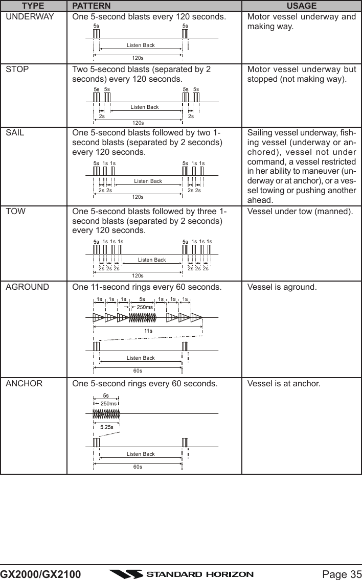
![GX2000/GX2100Page 3410.15.2 Operating the FOG HORN modeOperator can select from “Underway”, “Stop”, “Sail”, “Tow”, “Aground”, “An-chor”, “Horn”, and “Siren”.1. Press the [PA] key, then select “FogFogFogFogFog” with the CHknob.2. Press the CH knob.3. Turn the CH knob to select one of the eight func-tions described above.4. Press the CH knob.5. On the “HornHornHornHornHorn” and “SirenSirenSirenSirenSiren” modes, press the PTTswitch to activate the tone (fog signal) through theHAIL/PA speaker.Turn the CH knob to control the AF output level. TheAF output level can be set from 0 to 30 watts.6. When the fog signal is not outputted, turn the PWR/VOL knob to adjust listen back volume.7. To exit the FOG HORN mode, press the [CLR(WX)] key.](https://usermanual.wiki/Yaesu-Musen/30443X3D.Users-Manual/User-Guide-1203519-Page-34.png)
![GX2000/GX2100Page 3610.16INTERCOM OPERATIONConnecting a CMP30 (RAM3) Remote Station Microphone or VH-310 Hand-set to the GX2000/GX2100 allows intercom communications. Refer to sec-tion “13.2 INTERCOM OPERATION” for CMP30 (RAM3) Remote Station Mi-crophone or section “14.2 INTERCOM OPERATION” for VH-310 Handset.10.16.1 Communication1. Press the [IC] key while in the “Radio” mode, the mode is changed to“Intercom” mode.2. When the “Intercom” operation is activated, “IntercomIntercomIntercomIntercomIntercom” is displayed on theGX2000/GX2100, and “IC” is displayed on the CMP25 RAM+ or VH-310 Handset.3. Press the PTT switch. “TalkTalkTalkTalkTalk” will be shown on the display.NOTE: A warning beep will be emitted when the GX5000S microphone’sPTT switch is pressed while the RAM+ Mic’s PTT switch is pressed.4. Speak slowly and clearly into the microphone, hold the microphone about1/2 inch away from your mouth.5. When finished, release the PTT switch.6. Press the [DW(IC)] key the mode will revert to “Ra-dio” mode.10.16.2 CallingHold down the [DW(IC)] key when the “In-tercom” mode is activated to send a call-ing beep to the RAM+ or VH-310 remotemic.(Second Station Mic’s PTT switch is pressed)(GX5000S’s PTT switch is pressed)](https://usermanual.wiki/Yaesu-Musen/30443X3D.Users-Manual/User-Guide-1203519-Page-36.png)