Yaesu Musen 30443X3D MOBILE MARINE TRANSCEIVER User Manual GX2000S GX2100S Owner s Manual pmd
Yaesu Musen Co., Ltd. MOBILE MARINE TRANSCEIVER GX2000S GX2100S Owner s Manual pmd
Contents
- 1. Users Manual
- 2. Operating Manual 1
- 3. Operating Manual 2
Users Manual
Page 1GX2000S/GX2100S
MATRIX GX2000/GX2100
25 Watt VHF/FM
Marine Transceiver
Owner's Manual
GX2000/GX2100Page 2
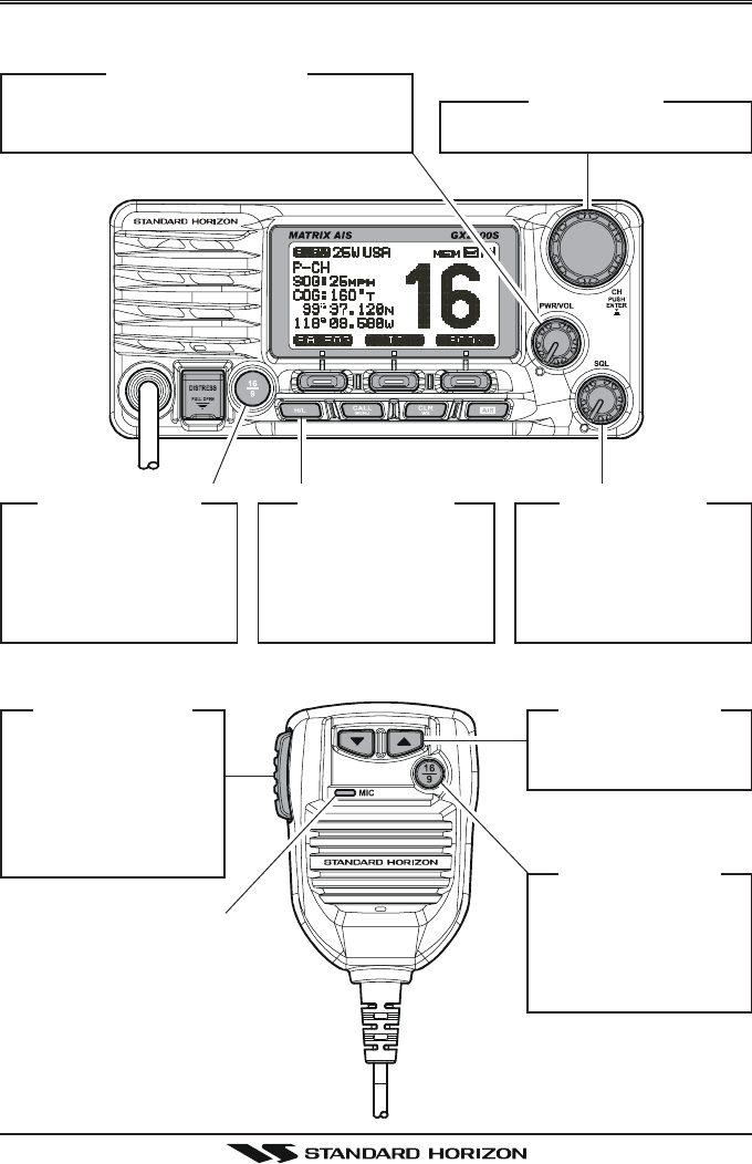
QUICK REFERENCE GUIDE I
You can do the basic operation in numerical order of the illustration below.
h
[PTT] S
WITCH
Speak into the
microphone in a
normal voice level
while pressing this
switch.
d
[TT
TT
T] / [SS
SS
S] K
EY
Selects the operating
channel.
f
[H/L] B
UTTON
When pressed,
toggles the transmit
power between High
(25W) and Low (1W).
e
[SQL] K
NOB
Move this control
clockwise to squelch
or counter clockwise
un-squelch the radio.
c
[PWR/VOL] K
NOB
Press and hold this knob until the LCD
turns on, and adjust the audio level.
d
[CH] K
NOB
Selects the operating channel.
g
[16/9] B
UTTON
yPress to recall chan-
nel 16.
yPress and hold to
recall channel 9.
g
[16/9] B
UTTON
yPress to recall
channel 16.
yPress and hold to
recall channel 9.
M
ICROPHON
Page 3GX2000/GX2100
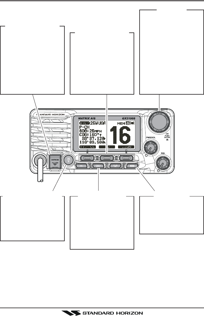
[DISTRESS] B
UTTON
Note: for this key to
operate a MMSI must
be programmed.
Lift the red cover,
press the Distress but-
ton once, then press
and hold until the ra-
dio alarms.
QUICK REFERENCE GUIDE II
[CALL/MENU] B
UTTON
yPress to access the
“DSC MENU”.
yPress and hold to
access the “SETUP
MENU”.
[CH] K
NOB
ySelect the operating
channel.
ySelect the item in
the “SETUP MENU”
and “DSC MENU”.
yWhen the “SETUP
MENU” or “DSC
MENU” is selected,
pressing this knob
saves a selection.
[CLR/WX] B
UTTON
yPress to cancel the
menu selection.
yPress and hold to
recall the last-used
NOAA Weather
Channel.
[P
ROGRAMMABLE
] K
EY
These three keys
functions can be cus-
tomized by the Setup
Menu mode.
The factory defaults
are [PA/FOG], [IC],
and [SCAN] key.
[AIS] B
UTTON
Press to change the
display to AIS (Auto-
matic Identification
System) mode
GX2000/GX2100Page 4
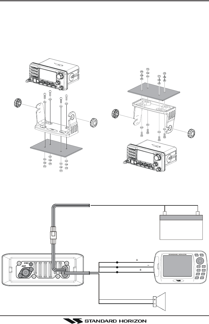
QUICK INSTALLATION GUIDE I
DESKTOP MOUNTING OVERHEAD MOUNTING
DESKTOP/OVERHEAD MOUNTING THE RADIO
The supplied universal mounting bracket allows desktop or overhead nounting.
Use a 13/64” (5.2-mm) bit to drill the holes to a surface which is more 0.4 inch
(10 mm) thick and can support more than 3.3 lbs (1.5 kg) and secure the
bracket with the supplied screws, spring washers, flat washers, and nuts.
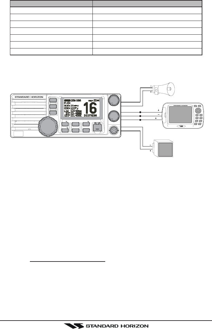
ELECTRICAL CONNECTIONS
GPS Receiver
Plotter ConnectionRadio Wires
External Speaker
Green
Purple
Red Black
NMEA OUT
NMEA COMMON
NMEA IN
( )
( )
( )
Blue
Shield
White
12 V Battery
Page 5GX2000/GX2100
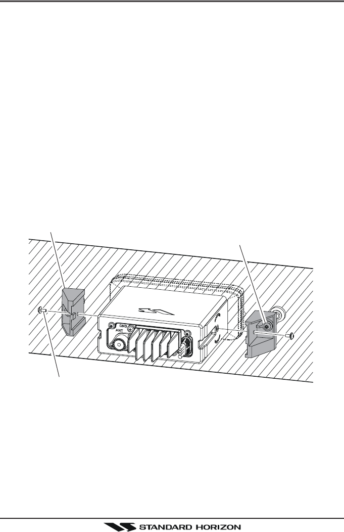
QUICK INSTALLATION GUIDE II
FLUSH MOUNTING
Bracket
Adjusting Screw
Lock-washer nut combination
FLUSH MOUNTING THE RADIO
The optional MMB-84 Flush-Mount Bracket allows flush mounting the radio to
your vessel.
1. To assist in flush mounting, a template has been included. Use this tem-
plate to assess the mounting location.
2. Use the template to mark the location where the rectangular hole is to be
cut. Confirm the space behind the dash or panel is deep enough to accom-
modate the transceiver (at least 6.7 inches or 17 cm deep).
There should be at least 1/2 inch (1.3 cm) between the transceiver’s heatsink
and any wiring, cables or structures.
3. Cut out the rectangular hole and insert the transceiver.
4. Fasten the brackets to the sides of the transceiver with the lock washer nut
combination; so that the mounting screw base faces the mounting surface.
5. Turn the adjusting screw to adjust the tension so that the transceiver is
tight against the mounting surface.

GX2000/GX2100Page 6
1 GENERAL INFORMATION
1.1 INTRODUCTION
The STANDARD HORIZON GX2000/2100 is a VHF/FM Marine Transceiver
designed for use in the frequency range of 156.025 to 163.275 MHz. The
GX2000/2100 can be operated from 11 to 16 VDC and has a switchable RF
output power of 1 watt or 25 watts.
The GX2100 is equipped with the AIS (Automatic Identification System) re-
ceiver and its display program which enables to identify and avoid other large
vessels nearby your vessel. The GX2100 is equipped with the display pro-
gram of the AIS too. Threrfore, the GX2000 also enables to identify and avoid
other large vessels nearby your vessel, if the AIS receiver (not supply) is
commected.
The GX2000/GX2100 is capable of DSC (Digital Selective Calling) Class D
operation and an Enhanced second station RAM+ mic (CMP30 remote-con-
trol speaker/microphone with display) or VH-310 Handset. Class D operation
allows continuous receiving of Digital Selective Calling functions on channel
70 even if the radio is receiving a call.
The GX2000/GX2100 operates on all currently-allocated marine channels
which are switchable for use with USA, International, or Canadian regulations.
It has an emergency channel 16 which can be immediately selected from any
channel by pressing the red [16/9] key. NOAA Weather channels can also be
accessed immediately by Press and holding the [CLR(WX)] key with channel
selection.
Other features of the GX2000/GX2100 include: 30W PA/Fog, multi-station
intercom, scanning, priority scanning, submersible speaker mic, high and low
voltage warning, and GPS repeatability.
2 PACKING LIST
When the package containing the transceiver is first opened, please check it
for the following contents:
yGX2000 or GX2100 Transceiver
yMounting Bracket and attaching hardware
yOwner’s Manual
yWarning Sticker
yPower Cord

Page 7GX2000/GX2100
3 OPTIONS
MMB-84 .........................................................................Flush-Mount Bracket
CMP30B/W ............... Remote-Access Microphone (RAM+ Mic, Black/White)
VH-310 .................................................. Remote Handset (available in Black)
CT-100 ............................................... 23-foot Extension Cable for RAM+ Mic
CVS2500 ...............................................................................Voice Scrambler
MLS-310 .............. 10W amplified External Speaker with on/off Volum control
MLS-300 ...................................................................... External Loudspeaker
101W ............................................................... Mini White Extension Speaker
220SW ..................................................................... 4.5” Round Hail/PA Horn
240SW ........................................................ 5” x 8” Rectangular Hail/PA Horn
MEK-4 .... Microphone Extension Kit (to remote front panel mic to rear panel)
4 SAFETY / WARNING INFORMATION
This radio is restricted to occupational use, work related operations only where
the radio operator must have the knowledge to control the exposure condi-
tions of its passengers and bystanders by maintaining the minimum separa-
tion distance of 0.89 m (2.92 feet). Failure to observe these restrictions will
result in exceeding the FCC RF exposure limits.
Antenna Installation:
The antenna must be located at least 0.89 m (2.92 feet) away from passen-
gers in order to comply with the FCC RF exposure requirements.
Lithium Battery Included:
This radio contains a Lithium Battery. At the end of radio’s useful life, under
various state and lows, it may be illegal to dispose of Lithium Battery into the
municipal waste stream. Check with your local solid waste officials for details
in your area for recycling options or proper disposal.
ON-LINE WARRANTY REGISTRATION
Please visit www.standardhorizon.com to register the GX2000/
GX2100 Marine VHF. It should be noted that visiting the Web site from
time to time may be beneficial to you, as new products are released
they will appear on the STANDARD HORIZON Web site.
PRODUCT SUPPORT INQUIRIES
If you have any questions or comments regarding the use of the
GX2000/GX2100, you can visit the STANDARD HORIZON Web site
to send an E-Mail or contact the Product Support team at 800-767-2450
M-F 7:00-5:00PST.

GX2000/GX2100Page 8
5 FCC RADIO LICENSE INFORMATION
Standard Horizon radios comply with the Federal Communication Commis-
sion (FCC) requirements that regulate the Maritime Radio Service.
5.1 STATION LICENSE
An FCC ship station license is no longer required for any vessel traveling in
U.S. waters (except Hawaii) which is under 20 meters in length. However, any
vessel required to carry a marine radio on an international voyage, carrying a
HF single side band radiotelephone or marine satellite terminal is required to
have a ship station license. FCC license forms, including applications for ship
(605) and land station licenses can be downloaded via the Internet at http://
www.fcc.gov/Forms/Form605/605.html. To obtain a form from the FCC, call
(888) 225-5322.
5.2 RADIO CALL SIGN
Currently the FCC does not require recreational boaters to have a Ship Radio
Station License. The USCG recommends the boats registration number and
the state to be used.
5.3 CANADIAN SHIP STATION LICENSING
You may need a license when traveling in Canada. If you do need a license
contact their nearest field office or regional office or write:
Industry Canada
Radio Regulatory Branch
Attn: DOSP
300 Slater Street
Ottawa, Ontario
Canada, KIA 0C8
5.4 FCC / INDUSTRY CANADA INFORMATION
The following data pertaining to the transceiver is necessary to fill out the li-
cense application.
Type Acceptance ......................................................................... FCC Part 80
Output Power ...............................................1 Watt (low) and 25 Watts (high)
Emission .........................................................................16K0G3E, 16K0G2B
Frequency Range .................................................... 156.025 to 163.275 MHz
FCC Type Number ................................................................... K6630443X3D
Industry Canada Type Approval ............................................ 511B-30443X3S

Page 9GX2000/GX2100
6 FCC NOTICE
NOTICE
Unauthorized changes or modifications to this equipment may void com-
pliance with FCC Rules. Any change or modification must be approved
in writing by STANDARD HORIZON.
NOTICE
This equipment has been tested and found to comply with the limits for
a Class B digital device, pursuant to Part 15 of the FCC Rules. These
limits are designed to provide reasonable protection against harmful
interference in a residential installation. This equipment generates, uses
and can radiate radio frequency energy and, if not installed and used in
accordance with the instructions, may cause harmful interference to ra-
dio communications. However, there is no guarantee that interference
will not occur in a particular installation. If this equipment does cause
harmful interference to radio or television reception, which can be de-
termined by turning the equipment off and on, the user is encouraged to
try to correct the interference by one or more of the following measures:
- Reorient or relocate the receiving antenna.
- Increase the separation between the equipment and receiver.
- Connect the equpmet into an outlet on a circuit different from that to
which the receiver is connected.
- Consult the dealer or an experienced radio/TV technician for help.

GX2000/GX2100Page 10
7 GETTING STARTED
7.1 ABOUT VHF RADIO
The radio frequencies used in the VHF marine band lie between 156 and 158
MHz with some shore stations available between 161 and 163 MHz. The ma-
rine VHF band provides communications over distances that are essentially
“line of sight” (VHF signals do not travel well through objects such as buildings,
hills or trees). Actual transmission range depends much more on antenna type,
gain and height than on the power output of the transmitter. On a fixed mount
25W radio transmission expected distances can be greater than 15 miles, for
a portable 5W radio transmission the expected distance can be greater than 5
miles in “line of sight”.
7.2 SELECTING AN ANTENNA
Marine antennas are made to radiate signals equally in all horizontal direc-
tions, but not straight up. The objective of a marine antenna is to enhance the
signal toward the horizon. The degree to which this is accomplished is called
the antenna’s gain. It is measured in decibels (dB) and is one of the major
factors in choosing an antenna. In terms of effective radiated power (ERP),
antennas are rated on the basis of how much gain they have over a theoretical
antenna with zero gain. A 3 foot, 3dB gain antenna represents twice as much
gain over the imaginary antenna.
Typically a 3 foot 3dB gain stainless steel whip is used on a sailboat mast. The
longer 8 foot 6dB fiberglass whip is primarily used on power boats that require
the additional gain.
Page 11GX2000/GX2100
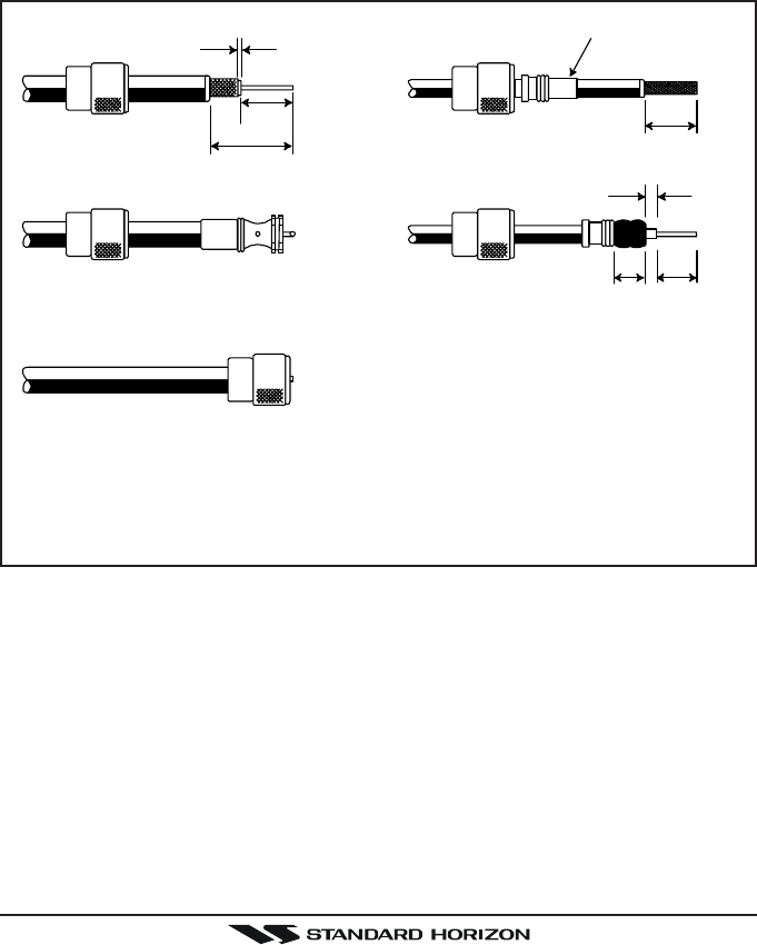
7.3 COAXIAL CABLE
VHF antennas are connected to the transceiver by means of a coaxial cable –
a shielded transmission line. Coaxial cable is specified by it’s diameter and
construction.
For runs less than 20 feet, RG-58/U, about 1/4 inch in diameter is a good
choice. For runs over 20 feet but less than 50 feet, the larger RG-8X or RG-
213/U should be used for cable runs over 50 feet RG-8X should be used. For
installation of the connector onto the coaxial cable refer to the figure below.
1/16''
3/4''
3/4''
1 1/8''
1/8''
5/8''3/8''
Adapter
To get your coax cable through a fitting and into your boat’s interior, you
may have to cut off the end plug and reattach it later. You can do this if
you follow the directions that come with the connector. Be sure to make
good soldered connections.

GX2000/GX2100Page 12
8 INSTALLATION
8.1 LOCATION
The radio can be mounted at any angle. Choose a mounting location that:
• is far enough from any compass to avoid any deviation in compass read-
ing due to the speaker magnet
• provides accessibility to the front panel controls
• allows connection to a power source and an antenna
• has nearby space for installation of a microphone hanger
• the antenna must be mounted at least 3 feet from radio
Note: To insure the radio does not affect the compass or radios performance is
not affected by the antenna location, temporarily connect the radio in the de-
sired location and:
a. Examine the compass to see if the radio causes any deviation
b. Connect the antenna and key the radio. Check to ensure the radio is
operating correctly by requesting a radio check.
8.2 MOUNTING THE RADIO
8.2.1 Supplied Universal Mounting Bracket
The supplied universal mounting bracket allows overhead or desktop mount-
ing.
Use a 13/64” (5.2-mm) bit to drill the holes to a surface which is more 0.4 inch
(10 mm) thick and can support more than 3.3 lbs (1.5 kg) and secure the
bracket with the supplied screws, spring washers, flat washers, and nuts.
Page 13GX2000/GX2100
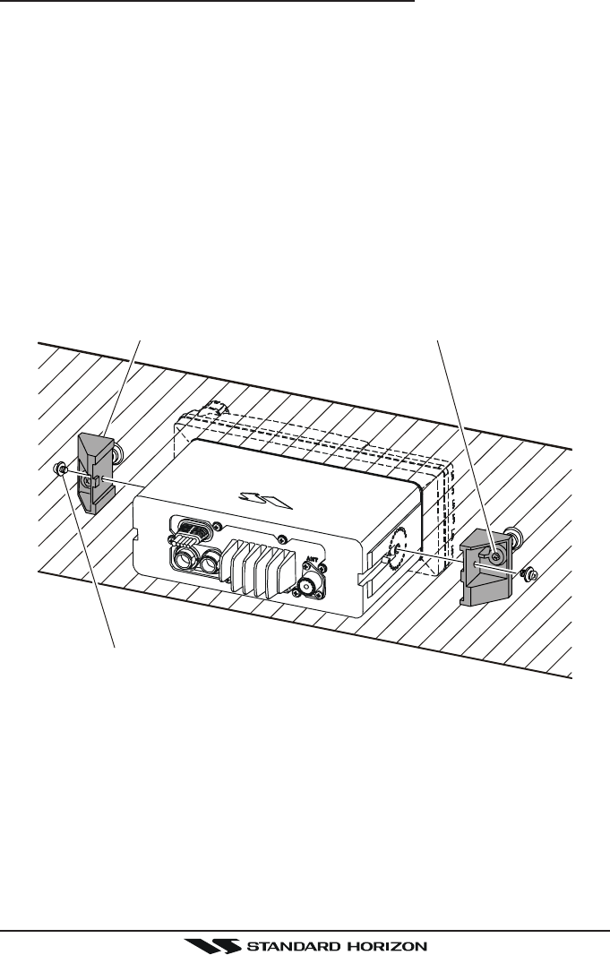
8.2.2 Optional MMB-84 Flush Mount Bracket
1. Make a rectangular template for the flush mount measuring 2.9” H x
8.1” W (72 x 205 mm).
2. Use the template to mark the location where the rectangular hole is to be
cut. Confirm the space behind the dash or panel is deep enough to accom-
modate the transceiver (at least 6 inches deep).
There should be at least 1/2 inch between the transceiver’s heatsink and
any wiring, cables or structures.
3. Cut out the rectangular hole and insert the transceiver.
4. Fasten the brackets to the sides of the transceiver with the lock washer nut
combination; so that the mounting screw base faces the mounting surface
(see illustration below).
5. Turn the adjusting screw to adjust the tension so that the transceiver is
tight against the mounting surface.
Bracket Adjusting Screw
Lock-washer nut combination
GX2000/GX2100Page 14
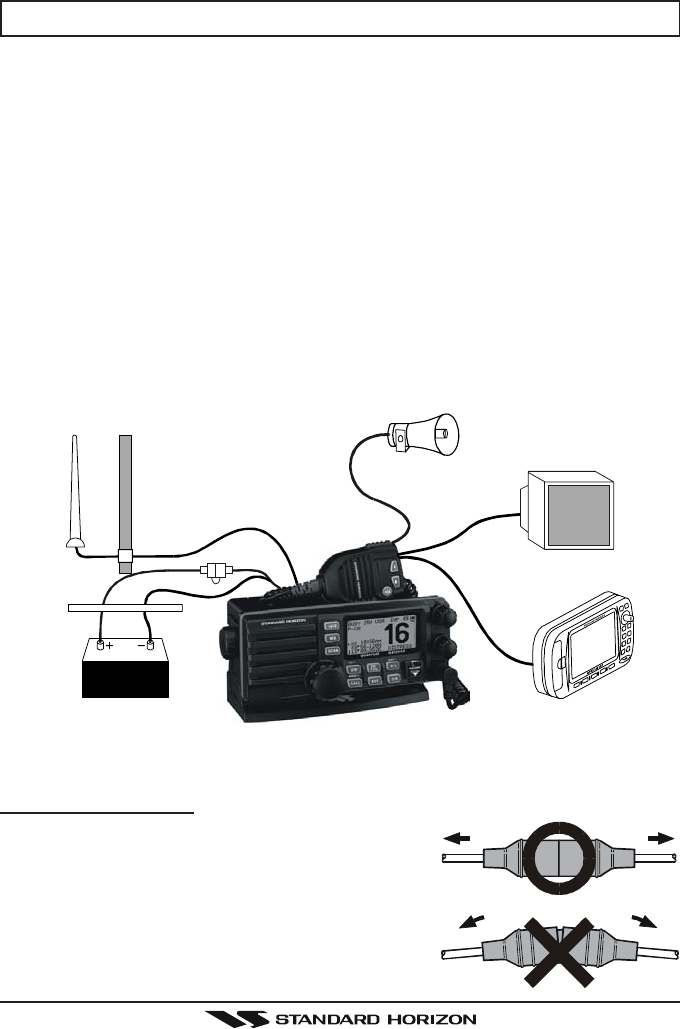
8.3 ELECTRICAL CONNECTIONS
CAUTION
Reverse polarity connections will damage the radio!
Connect the power cord and antenna to the radio. Antenna and Power Supply
connections are as follows:
1. Mount the antenna at least 3 feet away from the radio. At the rear of the
radio, connect the antenna cable. It must have a PL259 connector. RG-8/
U coaxial cable must be used if the antenna is 25 feet or more from the
radio. RG58 cable can be used for distances less than 25 feet.
2. Connect the red power wire to a 13.8 VDC ±20% power source. Connect
the black power wire to a negative ground.
3. If an optional remote extension speaker is to be used, refer to section 3.3
for connections.
4. It is advisable to have a Certified Marine Technician check the power out-
put and the standing wave ratio of the antenna after installation.
GPS Navigation Receiver
Accessory Cable
Optional Speaker
Antenna
Fuse
Red
Power Source
Black
Water proof
Deck Outlet
Optional HAIL/PA Horn
Fuse Replacement
To take out the Fuse from the Fuse Holder, hold
the both ends of the Fuse Holder and pull the Fuse
Holder apart, do not bend the Fuse Holder. When
you replace the Fuse, please confirm that the Fuse
is tightly fixed on the metal contact located inside
the Fuse Holder. If the metal contact holding the
fuse is loose, the Fuse holder may heat up.
Page 15GX2000/GX2100
Wire Color/Description
WHITE - External Speaker (+)
SHIELD - External Speaker (–)
RED - PA Speaker (+)
SHIELD - PA Speaker (–)
GREEN - NMEA Ground
BLUE- NMEA Input (+)
GRAY-NMEA Output (+)
Connection Examples
Connect to external 4 Ohm audio speaker
Connect to external 4 Ohm audio speaker
Connect to external 4 Ohm PA speaker
Connect to external 4 Ohm PA speaker
Connect to NMEA (–) connection of GPS
Connect to NMEA (+) output of GPS
Connect to NMEA (+) input of GPS
8.4 ACCESSORY CABLE
External Speaker
GPS Receiver
PA Speak er
Green
Blue NMEA OUT
NMEA OUT
NMEA IN
( )
( )
( )
Gray
Shield
Shield
Red
White
DISTRESS
PULL OPEN
VOL/PWR
SQL
CALL CLR
PA/
FOG
SCAN
ENT
DW
IC NAV
MENU
WX
16/9
QUANTUM GX5000S
H/L
When connecting the external speaker or GPS navigation receiver, strip off
about 1 inch (2.5 cm) of the specified wire’s insulation, then splice the ends
together.
• The GPS must have the NMEAut turned on and set to 4800 Baud in
the setup menu. If there is a selection for parity select none.
• For further information on interfacing /setting up your GPS. Please contact
the manufacturer of the GPS receiver.
•GX2000/GX2100 can read NMEA-0183 version 2.0 or higher.
• The NMEA supported sentences are:
Input: GLL, GGA, RMC and GNS (RMC sentence is recommended)
Output:DSC and DSE
(DSC sentences to Standard Horizon Plotter for Position Polling)
If you have further inquires, please feel free to contact Product Support at:
Phone: (800) 767-2450
Email: marinetech@vxstdusa.com
GX2000/GX2100Page 16
OFFSET TIME TABLE
8.5 CHECKING GPS CONNECTIONS
After connections have been made between the
GX2000/GX2100 and the GPS, a small satellite icon
will appear on the top right corner of the LCD displayand
displays your current location (Latitude/Longitude) on
the display.
NOTE
If there is a problem with the NMEA input from a GPS, the GPS icon will
blink continuously until the connection is corrected.
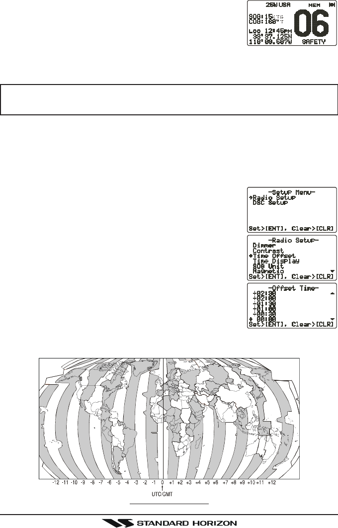
8.6 CHANGING THE GPS TIME
From the Factory the GX2000/GX2100 shows GPS satellite time or UTC
time when a optional GPS is connected. A time offset is needed to show the
local time in your area.
1. Press and hold down the [CALL(MENU)] key until
“SETUP MENUSETUP MENU
SETUP MENUSETUP MENU
SETUP MENU” appears, then select “GENERALGENERAL
GENERALGENERAL
GENERAL
SETUPSETUP
SETUPSETUP
SETUP” with the CH knob.
2. Press the CH knob, then select “TIME OFFSETTIME OFFSET
TIME OFFSETTIME OFFSET
TIME OFFSET” with
the CH knob.
3. Press the CH knob, then turn the CH knob to select
time offset from UTC. See illustration below to find
your offset time from UTC. If “00:0000:00
00:0000:00
00:00” is assigned,
the time is the same as UTC (Universal Time Coor-
dinated or GMT Greenwich Mean Time).
4. Press the CH knob to store the time offset.
5. Press the [CLR(WX)] key several times to return to
radio operation.

Page 17GX2000/GX2100
8.7 CHANGING THE TIME LOCATION
Set the radio show UTC time or local time with the offset inputted in section 8.6
CHANGING THE GPS TIME.
1. Press and hold down the [CALL(MENU)] key until
“SETUP MENUSETUP MENU
SETUP MENUSETUP MENU
SETUP MENU” appears, then select “GENERALGENERAL
GENERALGENERAL
GENERAL
SETUPSETUP
SETUPSETUP
SETUP” with the CH knob.
2. Press the CH knob, then select “TIME DISPLAYTIME DISPLAY
TIME DISPLAYTIME DISPLAY
TIME DISPLAY” with
the CH knob.
3. Press the CH knob.
4. Turn the CH knob to select “UTCUTC
UTCUTC
UTC” or “LOCALLOCAL
LOCALLOCAL
LOCAL”.
5. Press the CH knob to store the selected setting.
6. Press the [CLR(WX)] key several times to return to
radio operation.
8.8 CHANGING COG TO TRUE OR MAGNETIC
Allows the GPS Course Over Ground to be selected to show in True or Mag-
netic. Factory default is True however following the steps below the COG can
be changed to Magnetic.
1. Press and hold down the [CALL(MENU)] key until
“SETUP MENUSETUP MENU
SETUP MENUSETUP MENU
SETUP MENU” appears, then select “GENERALGENERAL
GENERALGENERAL
GENERAL
SETUPSETUP
SETUPSETUP
SETUP” with the CH knob.
2. Press the CH knob, then select “MAGNETICMAGNETIC
MAGNETICMAGNETIC
MAGNETIC” with
the CH knob.
3. Press the CH knob.
4. Turn the CH knob to select “MAGNETICMAGNETIC
MAGNETICMAGNETIC
MAGNETIC” or “TRUETRUE
TRUETRUE
TRUE”.
5. Press the CH knob to store the selected setting.
6. Press the [CLR(WX)] key several times to return to
radio operation.
GX2000/GX2100Page 18
8.9
OPTIONAL CMP30 ENHANCED RAM+ SECOND STATION MIC
OR VH-310 HANDSET INSTALLATION
The GX2000/GX2100 is capable of using a CMP30 Enhanced RAM+ mic
or VH-310 Handset to remotely control the Radio, DSC and PA/Fog functions.
In addition the GX2000/GX2100 can operate as a full function intercom
system.
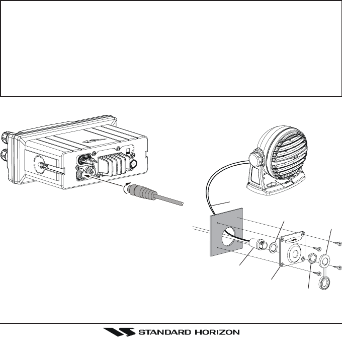
1. Connect the Extension Cable to the Remote Mic eight pin connector on
the rear panel, then tighten the Cable Nut (see illustration below).
2. Referring to illustration below, make a 1.2” (30 mm) hole in the wall, then
insert the Extension Cable into this hole. Connect the Gasket and Mount
Base to the Extension Cable Connector using the Nut.
3. Drill the four Screw holes (approx. 2 mm) on the wall, then install the Mount-
ing Base to the wall using four screws.
4. Put the Rubber Cap on to the Nut. The installation is now complete.
NOTE
The routing cable can be cut and spliced, however care needs to be
taken when reconnecting the wires to ensure water integrity.
Before cutting the cable make sur it is not plugged into the radio. After
cutting you will notice there are the following wires:
Yellow, Green, Brown, Purple, Blue, Green, RedÚ, ShieldÚ
ÚThe red and shield wires arewrapped in foil. Remove the foil, and
seperate the Red and shield wires.
Figure 3. Enhanced RAM+ MIC Installation
Wall
Gasket
Mounting Bracket
Routing Cable
Cap
Nut
External Speaker Connections
Page 19GX2000/GX2100
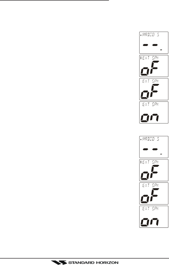
Remote Mic or External Speaker Selection
By default the RAM+ or VH-310 Handset internal speaker is turned on, how-
ever using the RAM+ mic (or VH-310 Handset) this speaker can be turned off
so the external speaker can be used.
RAM+ mic procedure
1. Press and hold the [CALL(ENT)] key.
2. Press the [S] or [T] key to select “RADIO SETUPRADIO SETUP
RADIO SETUPRADIO SETUP
RADIO SETUP.”
3. Press the [CALL(ENT)] key.
4. Press the [T] key to until “EXT SPKEXT SPK
EXT SPKEXT SPK
EXT SPK” is shown and press the
[CALL(ENT)] key.
5. Press the [S] or [T] key to select “oFoF
oFoF
oF” (External speaker
off) or “onon
onon
on” (External speaker on).
6. Press the [CALL(ENT)] key to save the selection.
7. Press the [16/9] key to exit this mode.
VH-310 Procedure
1. Press and hold the [CALL(MENU)] key.
2. Press the [S] or [T] key to select “RADIO SETUPRADIO SETUP
RADIO SETUPRADIO SETUP
RADIO SETUP.”
3. Press the [ENT] key
4. Press the [T] key to until “EXT SPKEXT SPK
EXT SPKEXT SPK
EXT SPK” is shown and press the
[ENT] key.
5. Press the [S] or [T] key to select “oFoF
oFoF
oF” (External speaker
off) or “onon
onon
on” (External speaker on).
6. Press the [ENT] key to save the selection.
7. Press the [16/9] key to exit this mode.
GX2000/GX2100Page 20
9 CONTROLS AND INDICATORS
NOTE
This section defines each control of the transceiver. See illustration at
the next page for location of controls. For detailed operating instructions
refer to chapter 10 of this manual.
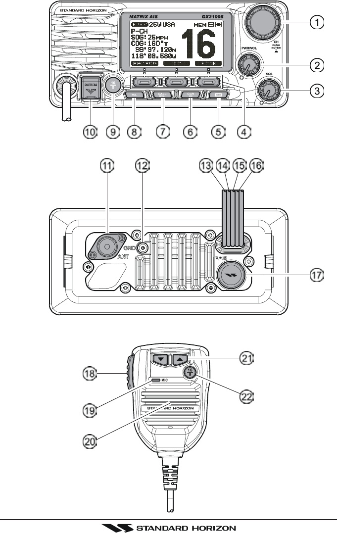
9.1 CONTROLS AND CONNECTIONS
CH Knob
Rotary knob used to select channels and to choose menu items (such as
the DSC menu, Radio Setup and DSC Setup menu). The [UP(S)] /
[DOWN(T)] keys on the microphone can also be used to select channels
and menu items.
SECONDARY USE
yPress this knob to enter a selection the “SETUP MENU” or “DSC MENU”.
yWhile holding down the [SCAN] key and turning this knob, you can con-
firm memory channels for scanning.
yAdjust the PA output level while in PA/FOG mode.
PWR/VOL Knob (Power Switch / Volume Control)
Turns the transceiver on and off as well as adjusts the audio volume.
To turn the transceiver on, press and hold this knob until the LCD turns on.
When the power is turned on, the transceiver is set to the last selected
channel. Clockwise rotation of this knob increases the audio volume level.
To turn the transceiver off, press and hold this knob until the LCD turns off.
SECONDARY USE
When in PA or Fog mode, controls the listen back volume.
SQL Knob (Squelch Control)
Adjusting this control clockwise, sets the point at which random noise on
the channel does not activate the audio circuits but a received signal does.
This point is called the squelch threshold. Further adjustment of the squelch
control will degrade reception of wanted transmissions.
Page 21GX2000/GX2100
GX2000/GX2100Page 22
Programmable Key
These three keys functions can be customized by the Setup Menu mode.
When press one of these key briefly, the key functions will appear at the
LCD bottom. The factory defaults are shown below.
[Left] Key: [PA] function
Press this key to activate the 30W PA or FOG Horn Function. Refer to
section “10.15 PA/FOG OPERATION” for details.
[Center] Key: [IC] function
Press this key to activate the intercom operation (operate between ra-
dio and option mic or handset), when the optional CMP30 (RAM3) Re-
mote Station Microphone or VH-310 Handset is connected. Refer to
section “10.16 INTERCOM OPERATION” for details.
[Right] Key: [SCAN] function
Press this key to start and stop the scanning of programmed channels.
Refer to section “10.13 SCANNING” for details.
SECONDARY USE
Press and hold this key to memorizes the selected channel into the
transceivers scan memory for scanning (“MEM” appears on the dis-
play). When press and hold again, it DELETES the channel from the
scan memory (“MEM” disappears from the display).
[AIS] Key
Press the [AIS] key to display the AIS (Automatic Identification System)
information on the display. Refer to section “10.14 AIS OPERATION” for
details.
[CLR(WX)] Key
Press the [CLR(WX)] key briefly to cancel a selection the “Setup Menu”
and “DSC Menu”.
Press and hold the [CLR(WX)] key to recall the previously selected NOAA
weather channel from any channel. Press and hold the [CLR(WX)] key
again reverts to the previous selected working channel.
SECONDARY USE
Press the [CLR(WX)] key while pressing and holding the [16/9] key to switch
the channel group between “USA”, “International”, and “Canadian”.
[CALL(MENU)] Key
Press the [CALL(MENU)] key to access the “DSC MENU”.
SECONDARY USE
Press and hold the [CALL(MENU)] key to access the “SETUP MENU”.

Page 23GX2000/GX2100
[H/L] Key
Press the [H/L(NAV)] key to toggle between 25 W (High) and 1 W (Low)
power. When the TX output power is set to “Low” while the transceiver is
on channel 13 or 67, the output power will temporarily switch from “Low” to
“High” power until the PTT is released. The [H/L] key does not function on
transmit inhibited and low power only channels.
[16/9] Key
Press the [16/9] key briefly to recall channel 16 from any channel location.
Press and hold the [CLR(WX)] key to recall channel 9. Pressing the [16/9]
key again reverts to the previous selected working channel.
SECONDARY USE
Press the [CLR(WX)] key while pressing and holding the [16/9] key to switch
the channel group between “USA”, “International”, and “Canadian”.
[DISTRESS] Key
Used to send a DSC Distress Call. To send the distress call refer to section
“11.3.1 Transmitting a DSC Distress Call.”
ANT Jack (Antenna Jack)
Connects an antenna to the transceiver. Use a marine VHF antenna with
an impedance of 50 ohms.
GND Terminal (Ground Terminal)
Connects the GX2000/GX2100 to a good ground, for safety and opti-
mum performance.
Install only the supplied screw or similar size (M3x6, Stainless Steel) screw.
Accessory Connection Cable (Green, Blue, Gray, & Brown)
Connects the GX2000/GX2100 to a GPS receiver and AIS receiver.
PA Speaker Connection Cable (Red & Shield)
Connects the GX2000/GX2100 to a optional PA speaker. See section
“3 OPTIONS” for a list of optional STANDARD HORIZON Speakers.
External Speaker Connection Cable (White & Shield)
an external speaker. See section “3 OPTIONS” for a list of optional STAN-
DARD HORIZON Speakers.
DC Input Cable
Connects the radio to a DC power supply capable of delivering 12 to 16V
DC.
GX2000/GX2100Page 24
RAM Connector (Remote Station Microphone Connector)
Connects the GX2000/GX2100 to the CMP30 (RAM3) Remote Station
Microphone or the VH-310 Handset. Refer to section “13 CMP30 (RAM3)
OPERATION” or “14 VH-310 HANDSET OPERATION” for details
PTT Switch (Push-To-Talk Switch)
Keys the transmitter when the transceiver is in Radio mode. If the trans-
ceiver is in the Intercom Operation mode (between the Remote Station
Microphone and the Radio), it activates the GX2000/GX2100 micro-
phone for voice communications.
Microphone
Transmits the voice message with reduction of background noise, using
Clear Voice Noise Reduction Technology.
Microphone Speaker
The same audio heard through internal radio speaker is heard through
microphone speaker.
[UP(S)] / [DOWN(T)] Keys
The [UP(S)] and [DOWN(T)] on the microphone function the same as the
CH knob on the front panel of the transceiver.
[16/9] Key
Pressing the [16/9] key immediately recalls channel 16 from any location.
Press and hold the [16/9] key to recall channel 9. Pressing the [16/9] key
again will revert the radio to the previous selected channel.
Page 25GX2000/GX2100
10 BASIC OPERATION
10.1 PROHIBITED COMMUNICATIONS
The FCC prohibits the following communications:
• False distress or emergency messages:
• Messages to “any boat” except in emergencies and radio tests;
• Messages to or from a vessel on land;
• Transmission while on land;
• Obscene, indecent, or profane language (potential fine of $10,000).
10.2 RECEPTION
1. After the transceiver has been installed, ensure that the power supply and
antenna are properly connected.
2. Press and hold the PWR/VOL knob until the radio turns on.
3. Turn the SQL knob fully counterclockwise. This state is known as “squelch
off”.
4. Turn up the PWR/VOL knob until noise or audio from the speaker is at a
comfortable level.
5. Turn the SQL knob clockwise until the random noise disappears. This state
is known as the “squelch threshold.”
6. Turn the CH knob to select the desired channel. Refer to the channel chart
on page for available channels.
7. When a message is received, adjust the volume to the desired listening
level. The “ ” indicator in the LCD is displayed indicating that the
channel is being used.
10.3 TRANSMISSION
1. Perform steps 1 through 6 of RECEPTION.
2. Before transmitting, monitor the channel to ensure it is clear.
THIS IS AN FCC REQUIREMENT!
3. Press the PTT (push-to-talk) switch. The “ ” indicator on the LCD is
displayed.
4. Speak slowly and clearly into the microphone.
5. When the transmission is finished, release the PTT switch.
NOTE
This is a noise-canceling microphone. Position the Oval Slot label “MIC”
within 1 inch (2.5 cm) from the mouth for optimum performance.

GX2000/GX2100Page 26
10.4 TRANSMIT TIME - OUT TIMER (TOT)
When the PTT switch on the microphone is held down, transmit time is limited to
5 minutes. This limits unintentional transmissions due to a stuck microphone.
About 10 seconds before automatic transmitter shutdown, a warning beep will be
heard from the speaker(s). The transceiver will automatically go to receive mode,
even if the PTT switch is continually held down. Before transmitting again, the
PTT switch must first be released and then pressed again.
10.5 SIMPLEX/DUPLEX CHANNEL USE
Refer to the VHF MARINE CHANNEL CHART (page ) for instructions on
use of simplex and duplex channels.
NOTE
All channels are factory-programmed in accordance with FCC (USA),
Industry Canada (Canada), and International regulations. Mode of op-
eration cannot be altered from simplex to duplex or vice-versa.
10.6 USA, CANADA, AND INTERNATIONAL MODE
1. To change the Channel Group, hold the [16/9] key and press the [WX] key.
The mode changes from USA to International to Canadian with each press
of the [CLR(WX)] key.
2. “USA” will be displayed on the LCD for USA mode, “INTL” will be displayed
for International mode, and “CAN” will be displayed for Canadian mode.
3. Refer to the VHF MARINE CHANNEL CHART (page ) for allocated chan-
nels in each mode.
10.7 NOAA WEATHER CHANNELS
1. To receive a NOAA weather channel, press and hold the [CLR(WX)] key
for 2 seconds from any channel. The transceiver will go to the last selected
weather channel.
2. Turn the CH knob on the radio or [UP(S)] / [DOWN(T)] keys on the micro-
phone to select a different NOAA weather channel.
3. To exit from the NOAA weather channels, press the [CLR(WX)] key. The
transceiver returns to the channel it was on prior to a weather channel.
10.7.1 NOAA Weather Alert
In the event of extreme weather disturbances, such as storms and hurricanes,
the NOAA (National Oceanic and Atmospheric Administration) sends a weather
alert accompanied by a 1050 Hz tone and subsequent weather report on one
of the NOAA weather channels. When the Weather Alert feature is enabled
(see section “12.11 WX ALERT”), the transceiver is capable of receiving this
alert if the following is performed:

Page 27GX2000/GX2100
1. Program NOAA weather channels into the transceiver’s memory for scan-
ning. Follow the same procedure as for regular channels under section
“10.13.2 Memory Scanning (M-SCAN).”
2. Press the [SCAN] key once to start memory scanning.
3. The programmed NOAA weather channels will be scanned along with the
regular-programmed channels. However, scanning will not stop on a nor-
mal weather broadcast unless a NOAA alert is received.
4. When an alert is received on a NOAA weather channel, scanning will stop and
the transceiver will emit a loud beep to alert the user of a NOAA broadcast.
5. Press the [CLR(WX)] key to stop the alert tone and receive the weather
report.
NOTE
If the [CLR(WX)] key is not pressed the alert tone will be emitted for 5
minutes and then the weather report will be received.
NOTE
The Weather Alert feature is also engaged while the transceiver is re-
ceiving on one of the NOAA weather channels.
10.7.2 NOAA Weather Alert Testing
NOAA tests the alert system ever Wednesday between 11AM and 1PM. To test
the GX2000/GX2100’s NOAA Weather feature, on Wednesday between
11AM and 1PM, setup as in section “10.7.1 NOAA Weather Alert” and confirm
the alert is heard.
10.8 EMERGENCY (CHANNEL 16 USE)
Channel 16 is known as the Hail and Distress Channel. An emergency may be
defined as a threat to life or property. In such instances, be sure the transceiver
is on and set to CHANNEL 16. Then use the following procedure:
1. Press the microphone push-to-talk switch and say “Mayday, Mayday, May-
day. This is , , ” (your vessel’s name).
2. Then repeat once: “Mayday, ” (your vessel’s name).
3. Now report your position in latitude/longitude, or by giving a true or mag-
netic bearing (state which) to a well-known landmark such as a navigation
aid or geographic feature such as an island or harbor entry.
4. Explain the nature of your distress (sinking, collision, aground, fire, heart
attack, life-threatening injury, etc.).
5. State the kind of assistance your desire (pumps, medical aid, etc.).
6. Report the number of persons aboard and condition of any injured.
7. Estimate the present seaworthiness and condition of your vessel.

GX2000/GX2100Page 28
8. Give your vessel’s description: length, design (power or sail), color and
other distinguishing marks. The total transmission should not exceed 1
minute.
9. End the message by saying “OVER”. Release the microphone button and
listen.
10. If there is no answer, repeat the above procedure. If there is still no re-
sponse, try another channel.
10.9 CALLING ANOTHER VESSEL (CHANNEL 16 OR 9)
Channel 16 may be used for initial contact (hailing) with another vessel.
However, its most important use is for emergency messages. This channel
must be monitored at all times except when actually using another channel.
It is monitored by the U.S. and Canadian Coast Guards and by other vessels.
Use of channel 16 for hailing must be limited to initial contact only. Call-
ing should not exceed 30 seconds, but may be repeated 3 times at 2-minute
intervals. In areas of heavy radio traffic, congestion on channel 16 resulting
from its use as a hailing channel can be reduced significantly in U.S. waters by
using channel 9 as the initial contact (hailing) channel for non-emergency
communications. Here, also, calling time should not exceed 30 seconds but
may be repeated 3 times at 2-minute intervals.
Prior to making contact with another vessel, refer to the channel charts in this
manual, and select an appropriate channel for communications after initial
contact. For example, Channels 68 and 69 of the U.S. VHF Charts are some of
the channels available to non-commercial (recreational) boaters. Monitor your
desired channel in advance to make sure you will not be interrupting other
traffic, and then go back to either channel 16 or 9 for your initial contact.
When the hailing channel (16 or 9) is clear, state the name of the other vessel
you wish to call and then “this is” followed by the name of your vessel and
your Station License (Call Sign). When the other vessel returns your call, im-
mediately request another channel by saying “go to,” the number of the other
channel, and “over.” Then switch to the new channel. When the new channel
is not busy, call the other vessel.
After a transmission, say “over,” and release the microphone’s push-to-talk
(PTT) switch. When all communication with the other vessel is completed, end
the last transmission by stating your Call Sign and the word “out.” Note that it
is not necessary to state your Call Sign with each transmission, only at the
beginning and end of the contact.
Remember to return to Channel 16 when not using another channel. Some
radios automatically monitor Channel 16 even when set to other channels or
when scanning.

Page 29GX2000/GX2100
10.10 MAKING TELEPHONE CALLS
To make a radiotelephone call, use a channel designated for this purpose, The
fastest way to learn which channels are used for radiotelephone traffic is to
ask at a local marina. Channels available for such traffic are designated Pub-
lic Correspondence channels on the channel charts in this manual. Some
examples for USA use are Channels 24, 25, 26, 27, 28, 84, 85, 86, and 87.
Call the marine operator and identify yourself by your vessel’s name, The marine
operator will then ask you how you will pay for the call (telephone credit card,
collect, etc.) and then link your radio transmission to the telephone lines.
The marine telephone company managing the VHF channel you are using
may charge a link-up fee in addition to the cost of the call.
10.11 OPERATING ON CHANNELS 13 AND 67
Channel 13 is used at docks and bridges and by vessels maneuvering in port.
Messages on this channel must concern navigation only, such as meeting and
passing in restricted waters.
Channel 67 is used for navigational traffic between vessels.
By regulation, power is normally limited to 1 Watt on these channels. Your
radio is programmed to automatically reduce power to this limit on these chan-
nels. However, in certain situations it may be necessary to temporarily use a
higher power. See page 23 (H/L key) for means to temporarily override the
low-power limit on these two channels.
10.12 DUAL WATCH (TO CHANNEL 16)
1. Adjust the SQL knob until the background noise disappears.
2. Select the channel you wish to dual watch to CH16.
3. Press the [DW(IC)] key. The display will scan between CH16 and the chan-
nel that was selected in step 2.
If a transmission is received on the channel selected
in step 2, the GX2000/GX2100 will dual watch to
CH16.
4. To stop Dual Watch press the [DW(IC)] key again.
GX2000/GX2100Page 30
10.13 SCANNING
Allows the user to select the scan type from Memory scan or Priority scan.
“Memory scan” scans the channels that were programmed into memory. “Pri-
ority scan” scans the channels programmed in memory with the priority chan-
nel.
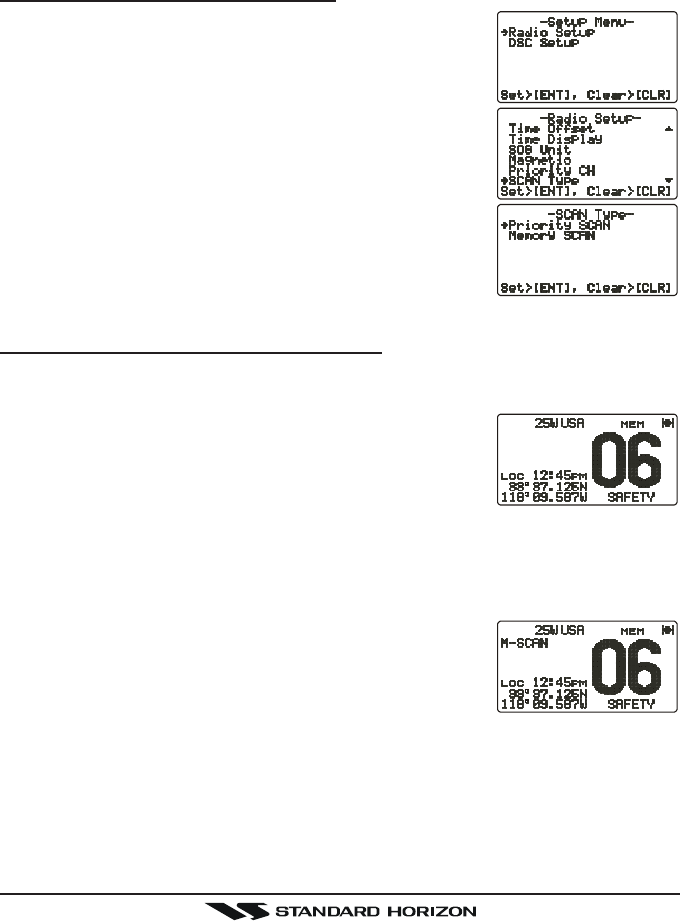
10.13.1 Selecting the Scan Type
1. Press and hold down the [CALL(MENU)] key until
“Setup MenuSetup Menu
Setup MenuSetup Menu
Setup Menu” appears.
2. Press the CH knob, then select “CH Function SetupCH Function Setup
CH Function SetupCH Function Setup
CH Function Setup”
with the CH knob.
3. Press the CH knob, then select “SCAN TypeSCAN Type
SCAN TypeSCAN Type
SCAN Type” with
the CH knob.
4. Press the CH knob.
5. Turn the CH knob to select “Priority SCANPriority SCAN
Priority SCANPriority SCAN
Priority SCAN” or
“Memory SCANMemory SCAN
Memory SCANMemory SCAN
Memory SCAN.”
6. Press the CH knob to store the selected setting.
7. Press the [CLR(WX)] key several times to return to
radio operation.
10.13.2 Memory Scanning (M-SCAN)
1. Adjust the SQL knob until background noise disappears.
2. Select a desired channel to be scanned using the CH knob.
3. Press the one of the Programmable key momen-
tarily to indicate these function on the LCD, then
press and hold the [SCAN] key until “MEM” appears
on the LCD which indicates the channel has been
programmed into the transceivers memory.
4. Repeat steps 2 and 3 for all the desired channels to be scanned.
5. To DELETE a channel from the transceiver’s memory, select the channel
then press and hold the [SCAN] key until “MEM” disappears from the LCD.
6. To start scanning, press the [SCAN] key momen-
tarily. “M-SCANM-SCAN
M-SCANM-SCAN
M-SCAN” appears on the LCD. Scanning will
proceed from the lowest to the highest programmed
channel number and will stop on a channel when a
transmission is received.
7. The channel number will blink during reception.
8. To stop scanning, press the [16/9] or [CLR(WX)] key.
Page 31GX2000/GX2100
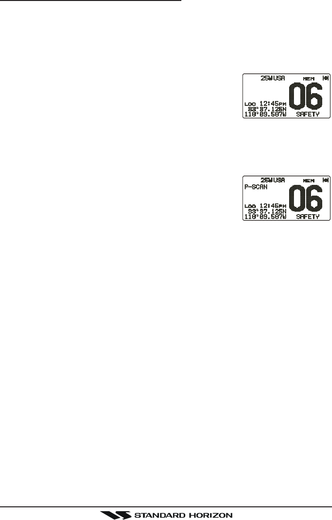
10.13.3 Priority Scanning (P-SCAN)
In the default setting, Channel 16 is set as the priority channel. You may change
the priority channel to the desired channel from the Channel 16 by the Radio
Setup Mode, refer to section “12.7 PRIORITY CHANNEL SET.”
1. Adjust the SQL knob until background noise disappears.
2. Select a desired channel to be scanned using the CH knob.
3. Press the one of the Programmable key momen-
tarily to indicate these function on the LCD, then
press and hold the [SCAN] key for one second,
“MEM” will appear on the display which indicates
the channel has been programmed into the transceivers memory.
4. Repeat steps 2 and 3 for all the desired channels to be scanned.
5. To DELETE a channel from the transceiver’s memory, select the channel
then press and hold the [SCAN] key until “MEM” disappears from the LCD.
6. To start priority scanning, press the [SCAN] key
momentarily. “P-SCANP-SCAN
P-SCANP-SCAN
P-SCAN” appears on the LCD. Scan-
ning will proceed between the memorized channels
and the priority channel. The priority channel will be
scanned after each programmed channel.
7. To stop scanning, press the [16/9] or [WX] key.
You may change the scan resume time in the Radio Setup Mode, refer to
section “12.9 SCAN RESUME TIME.”

GX2000/GX2100Page 32
10.14 AIS OPERATION
The GX2000 is equipped with an AIS (AUTOMATIC IDENTIFICATION SYSTEM) re-
ceiver and can display the its received data on the display. Therefore, you
identify and avoid other large vessels nearby your vessel.
The GX2100 also can display the received data on the display if you connect
the AIS receiver (not prepared) to the Accessory Connection Cable.
1. Press the [AIS] key to appear the AIS screen. The LCD displays apparent
vessel which equipped the AIS.
2. Press the one of the Programmable key momentarily to indicate these
function on the LCD, then press the [LIST] key to appear the MMSI num-
ber of the vessels which displayed on the LCD.
3. Turn the CH knob to select the MMIS number, then press the [INFO] key to
show more information of that station.
4. If you wish to contact (Individual Call) that station, press the [CALL] key,
then turn the CH knob to select the operating channel you want to commu-
nicate on and press the CH knob.
5. Press the CH knob again to transmit the individual DSC signal. See page
?? for details regarding the “Individual Call” operation.
6. Press the [QUIT] key to return to radio screen.
Page 33GX2000/GX2100
10.15 PA/FOG OPERATION
The GX2000/GX2100 has a 30W Hailer built-in and can be used with any
4 Ohm PA Horns. Standard Horizon offers a small and a large PA horn called
the 220SW and 240SW. When in Hail mode the PA speaker Listen’s Back
(acts as a microphone and sends sound to the front panel speaker and the
speaker mic) through the PA horn speaker which provides two-way communi-
cations through the PA horn speaker.
NOTE
When in PA or FOG mode the GX2000/GX2100 will receive on the
last selected VHF channel before entering into the PA or FOG mode
and receive DSC calls.
PA HAIL mode:
PA HAIL mode allows the transceiver to be used as a power hailer when an
optional STANDARD HORIZON 220SW or 240SW HAIL/PA speaker is in-
stalled. The Hail mode has a listen-back feature which provides two way
communication through the HAIL/PA speaker.
FOG HORN mode:
Automatic signaling is transmitted through the HAIL/PA speaker. When the
Fog horn, Bells or Whistle signal is not being outputted the GX2000/
GX2100 listens back through the connected PA Horn speaker.
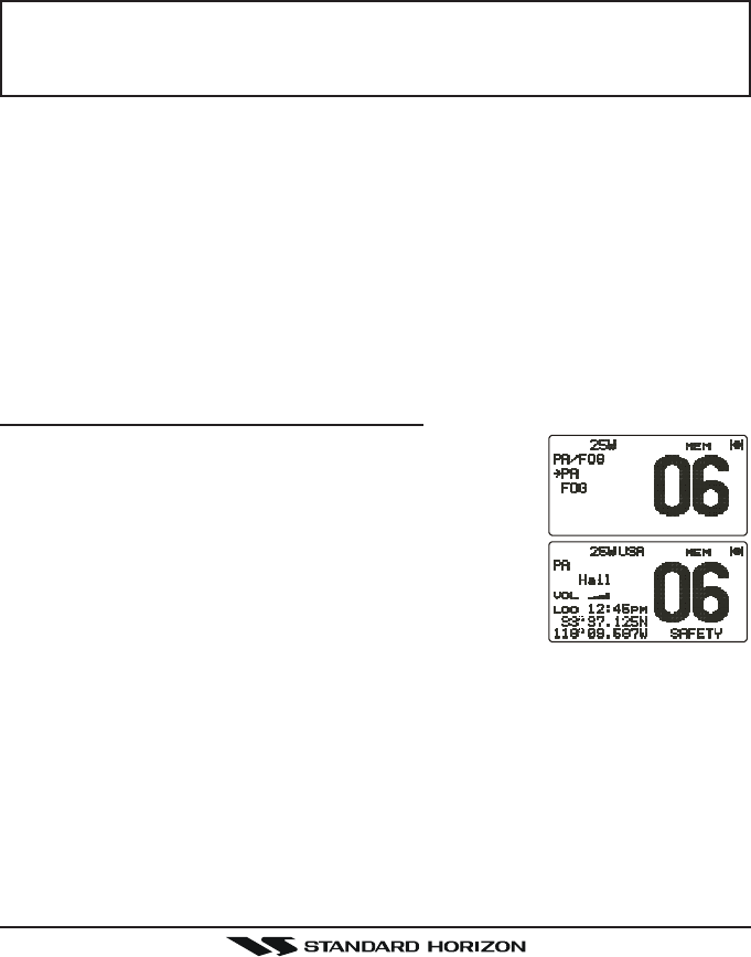
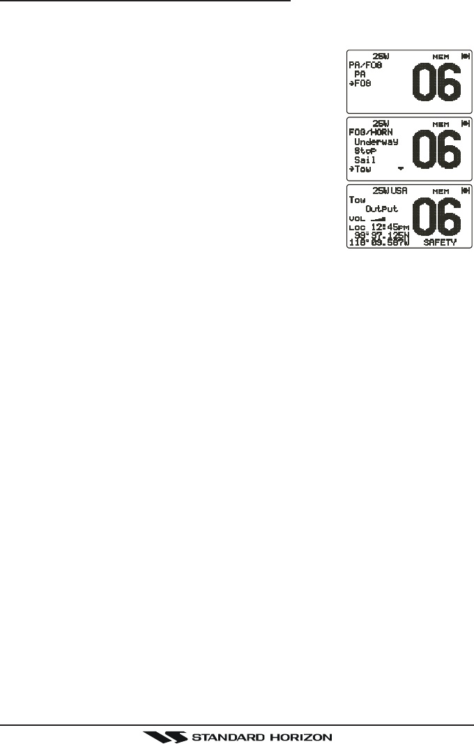
10.15.1 Operating the PA HAIL mode
1. Press the [PA] key, then select “PAPA
PAPA
PA” with the CH knob.
2. Press the CH knob.
3. Press the PTT switch to speak through the HAIL/PA
speaker.
Turn the CH knob to control the AF output level. The
AF output level can be set from 0 to 30 watts.
4. When the fog signal is not outputted, turn the PWR/
VOL knob to adjust listen back volume.
5. To exit the PA HAIL mode, press the [CLR(WX)] key.
GX2000/GX2100Page 34
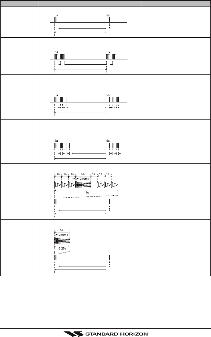
10.15.2 Operating the FOG HORN mode
Operator can select from “Underway”, “Stop”, “Sail”, “Tow”, “Aground”, “An-
chor”, “Horn”, and “Siren”.
1. Press the [PA] key, then select “FogFog
FogFog
Fog” with the CH
knob.
2. Press the CH knob.
3. Turn the CH knob to select one of the eight func-
tions described above.
4. Press the CH knob.
5. On the “HornHorn
HornHorn
Horn” and “SirenSiren
SirenSiren
Siren” modes, press the PTT
switch to activate the tone (fog signal) through the
HAIL/PA speaker.
Turn the CH knob to control the AF output level. The
AF output level can be set from 0 to 30 watts.
6. When the fog signal is not outputted, turn the PWR/
VOL knob to adjust listen back volume.
7. To exit the FOG HORN mode, press the [CLR(WX)] key.
Page 35GX2000/GX2100
TYPE PATTERN USAGE
120s
Listen Back
5s 5s
2s 2s
120s
Listen Back
1s 1s1s 1s
2s 2s2s 2s
120s
Listen Back
1s 1s1s 1s1s 1s
2s 2s2s 2s2s 2s
120s
Listen Back
60s
Listen Back
60s
Listen Back
UNDERWAY
STOP
SAIL
TOW
AGROUND
ANCHOR One 5-second rings every 60 seconds.
One 5-second blasts every 120 seconds.
Two 5-second blasts (separated by 2
seconds) every 120 seconds.
One 5-second blasts followed by two 1-
second blasts (separated by 2 seconds)
every 120 seconds.
One 5-second blasts followed by three 1-
second blasts (separated by 2 seconds)
every 120 seconds.
One 11-second rings every 60 seconds.
Motor vessel underway and
making way.
Motor vessel underway but
stopped (not making way).
Sailing vessel underway, fish-
ing vessel (underway or an-
chored), vessel not under
command, a vessel restricted
in her ability to maneuver (un-
derway or at anchor), or a ves-
sel towing or pushing another
ahead.
Vessel under tow (manned).
Vessel is aground.
Vessel is at anchor.
GX2000/GX2100Page 36
10.16INTERCOM OPERATION
Connecting a CMP30 (RAM3) Remote Station Microphone or VH-310 Hand-
set to the GX2000/GX2100 allows intercom communications. Refer to sec-
tion “13.2 INTERCOM OPERATION” for CMP30 (RAM3) Remote Station Mi-
crophone or section “14.2 INTERCOM OPERATION” for VH-310 Handset.
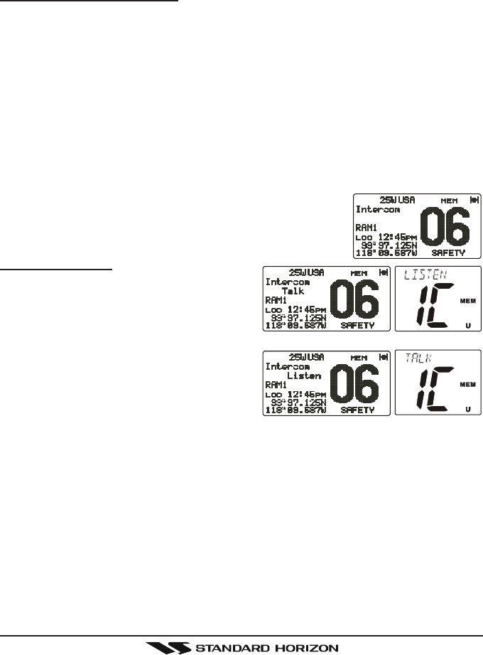
10.16.1 Communication
1. Press the [IC] key while in the “Radio” mode, the mode is changed to
“Intercom” mode.
2. When the “Intercom” operation is activated, “IntercomIntercom
IntercomIntercom
Intercom” is displayed on the
GX2000/GX2100, and “IC” is displayed on the CMP25 RAM+ or VH-
310 Handset.
3. Press the PTT switch. “TalkTalk
TalkTalk
Talk” will be shown on the display.
NOTE: A warning beep will be emitted when the GX5000S microphone’s
PTT switch is pressed while the RAM+ Mic’s PTT switch is pressed.
4. Speak slowly and clearly into the microphone, hold the microphone about
1/2 inch away from your mouth.
5. When finished, release the PTT switch.
6. Press the [DW(IC)] key the mode will revert to “Ra-
dio” mode.
10.16.2 Calling
Hold down the [DW(IC)] key when the “In-
tercom” mode is activated to send a call-
ing beep to the RAM+ or VH-310 remote
mic.
(Second Station Mic’s PTT switch is pressed)
(GX5000S’s PTT switch is pressed)

Page 37GX2000/GX2100
10.17 VOICE SCRAMBLER
If privacy of communications is desired, a CVS2500 4 code voice scrambler
(VS) can be installed in the transceiver. Contact your Dealer to have a CVS2500
installed. Refer to the section “12.17 VOICE SCRAMBLER” to program the
voice scrambler.
1. Select a channel that was programmed for scram-
bler mode (“VS” and scrambler number will appear
on the LCD).
2. Monitor the channel before transmitting.
3. Transmit the voice message. The signal sent will be scrambled.

Page 105GX2000S/GX2100S
Copyright 2009
VERTEX STANDARD CO., LTD.
All rights reserved.
No portion of this manual
may be reproduced
without the permission of
VERTEX STANDARD CO., LTD.
VERTEX STANDARD CO., LTD.
4-8-8 Nakameguro, Meguro-Ku, Tokyo 153-8644, Japan
VERTEX STANDARD
US Headquarters
10900 Walker Street, Cypress, CA 90630, U.S.A.
YAESU EUROPE B.V.
P.O. Box 75525, 1118 ZN Schiphol, The Netherlands
YAESU UK LTD.
Unit 12, Sun Valley Business Park, Winnall Close
Winchester, Hampshire, SO23 0LB, U.K.
VERTEX STANDARD HK LTD.
Unit 5, 20/F., Seaview Centre, 139-141 Hoi Bun Road,
Kwun Tong, Kowloon, Hong Kong
VERTEX STANDARD (AUSTRALIA) PTY., LTD.
Normanby Business Park, Unit 14/45 Normanby Road
Notting Hill 3168, Victoria, Australia