Yaesu Musen 30483X3D MARINE TRANSCEIVER User Manual GX1600 Owner s Manual pmd
Yaesu Musen Co., Ltd. MARINE TRANSCEIVER GX1600 Owner s Manual pmd
UserManual.wiki
>
Yaesu Musen
>
30483X3D User Manual
>
Users Manual 1
Contents
1.
Users Manual 1
2.
Users Manual 2
Users Manual 1
Navigation menu
Upload a User Manual
Namespaces
Wiki Guide
HTML
PDF
Info
Views
User Manual
Discussion / Help
Navigation
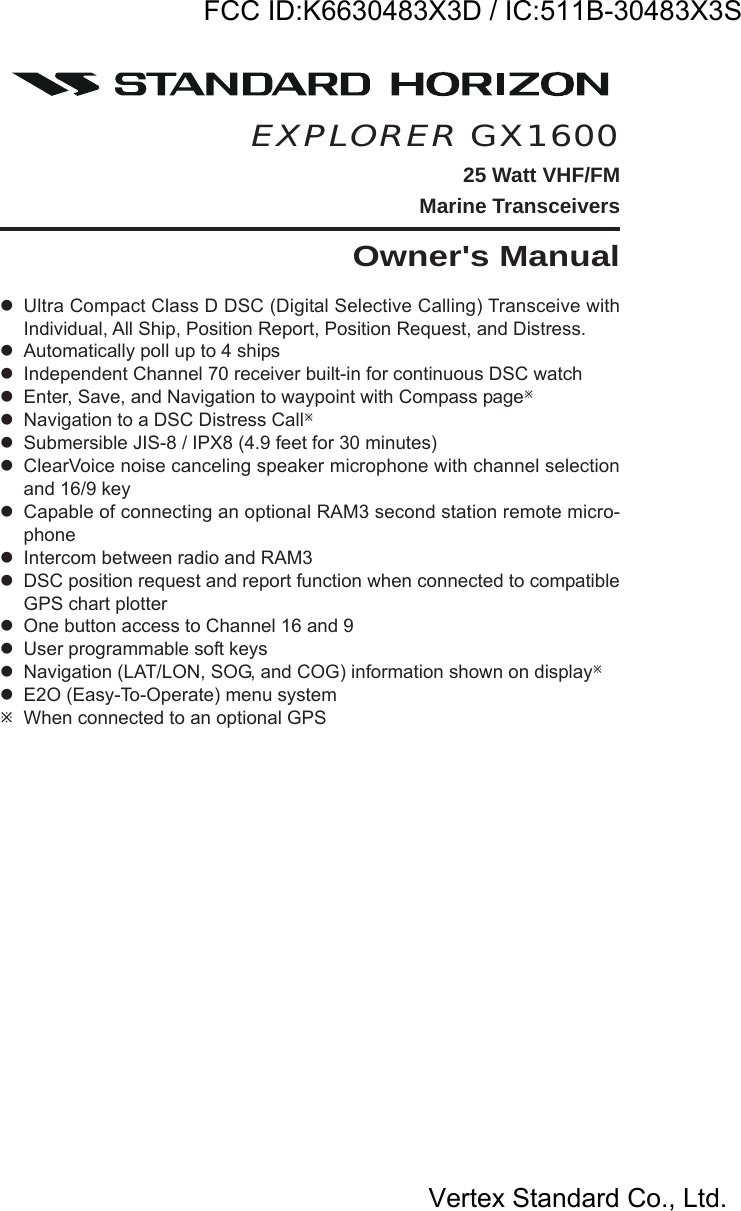
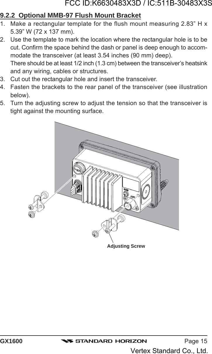
![GX1600Page 4QUICK REFERENCE GUIDEThis transceiver is equipped with the E2O (Easy-To-Operate) system. You cando the basic operation in numerical order of the illustration below.[PTT] SWITCHPlace your mouth about 1/2 inch away from Mic holeand speak in a normalvoice level while pressingthis switch.[PWR] BUTTONPress and hold this buttonto turn on or off the radio.MIC HOLE[VOL] KNOBAdjust the speaker audiovolume.[H/L] BUTTONWhen pressed, toggles thetransmit power betweenHigh (25W) and Low (1W).[SQL] KNOBMove this control clockwiseto squelch or counterclockwise un-squelch theradio.[16/9] BUTTONPress to recall channel 16.Press and hold to recallchannel 9.Press again to revert to thelast selected channel.[] / [] BUTTONSelects the operatingchannel.[H/L] KEYWhen pressed, toggles thetransmit power betweenHigh (25W) and Low (1W).[16/9] KEYPress to recall channel 16.Press and hold to recallchannel 9.Press again to revert to thelast selected channel.[] / [] KEYSelects the operatingchannel.FCC ID:K6630483X3D / IC:511B-30483X3SVertex Standard Co., Ltd.](https://usermanual.wiki/Yaesu-Musen/30483X3D.Users-Manual-1/User-Guide-1406710-Page-4.png)
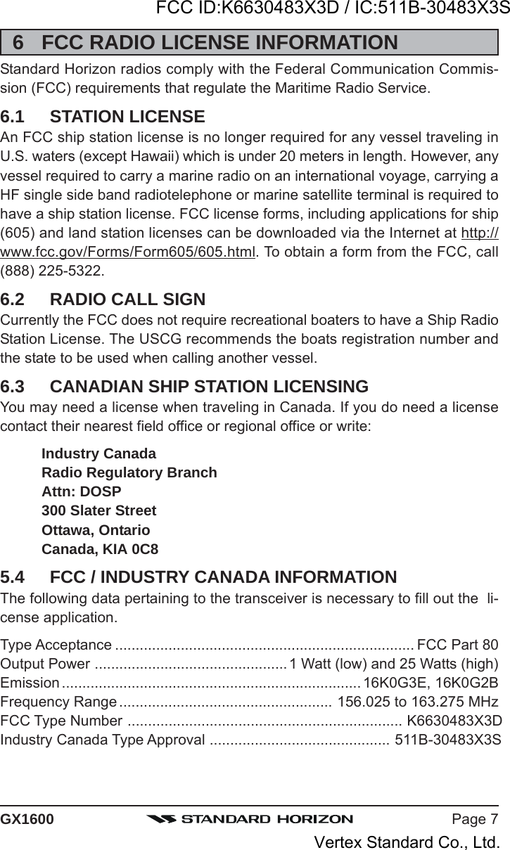
![Page 5GX16001 GENERAL INFORMATIONThe STANDARD HORIZON EXPLOPER GX1600 Marine VHF/FM Marinetransceiver are designed to be used in USA, International and Canadian Ma-rine bands. The GX1600 can be operated from 11 to 16 VDC and has a switch-able RF output power of 1 watt or 25 watts.The GX1600 VHF’s are capable of DSC (Digital Selective Calling) Class Doperation. Class D operation allows continuous receiving of Digital SelectiveCalling functions on channel 70 even if the radio is receiving a call. The GX1600VHF's operate on all currently-allocated marine channels which are switch-able for use with USA, International, or Canadian regulations. Emergency chan-nel 16 can be immediately selected from any channel by pressing the red key. NOAA Weather channels can also be accessed immediately by press-ing and holding the [WX] soft key.Other features of the GX1600 VHF’s include: Speaker Microphone, optionalRAM3 second station remote-control microphone with display, intercom be-tween radio and optional RAM3, scanning, priority scanning, submersiblespeaker mic, high and low voltage warning, and GPS repeatability.2 PACKING LISTWhen the package containing the transceiver is first opened, please check itfor the following contents:GX1600 TransceiverMounting Bracket and hardwareOwner’s ManualDSC Warning StickerFlush Mount TemplatePower Cord3 OPTIONSMMB-97 .........................................................................Flush-Mount BracketCMP30B/W ............... Remote-Access Microphone (RAM3 Mic, Black/White)CT-100 ............................................... 23-foot Extension Cable for RAM3 MicMLS-310 ............ 10W amplified External Speaker with on/off Volume controlMLS-300 .................................................................... External Loud SpeakerFCC ID:K6630483X3D / IC:511B-30483X3SVertex Standard Co., Ltd.](https://usermanual.wiki/Yaesu-Musen/30483X3D.Users-Manual-1/User-Guide-1406710-Page-5.png)
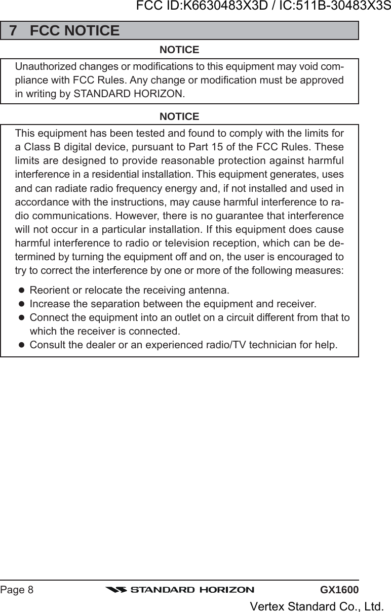
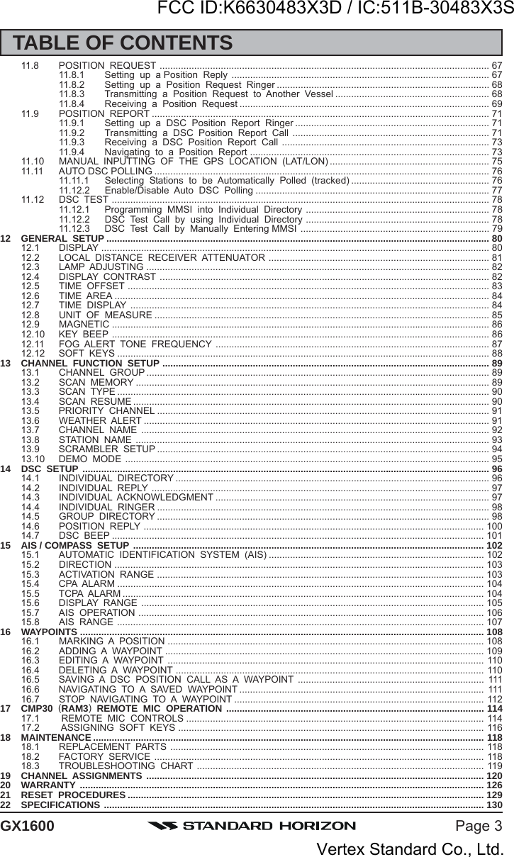
![GX1600Page 18OFFSET TIME TABLE9.5 CHECKING GPS CONNECTIONSAfter connections have been made between the GX1600and the GPS, a small satellite icon will appear on thetop right corner of the display and your current location(Latitude/Longitude) is shown on the display.NOTEIf there is a problem with the NMEA connection between the radio andthe GPS, the GPS icon will blink continuously until the connection iscorrected.9.6 CHANGING THE GPS TIMEFrom the Factory the GX1600 shows GPS satellite time or UTC time when anoptional GPS is connected. A time offset is needed to show the local time inyour area. The Time Offset must be changed in order for the radio to displaythe current time in your area. Please see the Offset Time Table at the bottomof this page.1. Press and hold down the key until “Setup MenuSetup MenuSetup MenuSetup MenuSetup Menu”appears, then select “GENERAL SETUPGENERAL SETUPGENERAL SETUPGENERAL SETUPGENERAL SETUP” with the/ key.2. Press the [SELECT] soft key, then select “TIME OFF-TIME OFF-TIME OFF-TIME OFF-TIME OFF-SETSETSETSETSET” with the / key.3. Press the [SELECT] soft key, then press the / key to select time offset of your location. Seeillustration below to find your offset time. If “00:0000:0000:0000:0000:00”is assigned, the time is the same as UTC (UniversalTime Coordinated or GPS Satellite Time).4. Press the [ENT] soft key to store the time offset.5. Press the [QUIT] soft key several times to return toradio operation.FCC ID:K6630483X3D / IC:511B-30483X3SVertex Standard Co., Ltd.](https://usermanual.wiki/Yaesu-Musen/30483X3D.Users-Manual-1/User-Guide-1406710-Page-18.png)
![Page 19GX16009.7 CHANGING THE TIME LOCATIONThis menu selection allows the radio to show UTC time or local time with theoffset.1. Press and hold down the key until “Setup MenuSetup MenuSetup MenuSetup MenuSetup Menu”appears, then select “GENERAL SETUPGENERAL SETUPGENERAL SETUPGENERAL SETUPGENERAL SETUP” with the/ key.2. Press the [SELECT] soft key, then press the / key to “TIME AREATIME AREATIME AREATIME AREATIME AREA”.3. Press the [SELECT] soft key.4. Press the / key to select “UTCUTCUTCUTCUTC” or “LOCALLOCALLOCALLOCALLOCAL”.5. Press the [ENT] soft key to store the selected set-ting.6. Press the [QUIT] soft key several times to return toradio operation.9.8 CHANGING THE TIME FORMATThis menu selection allows the radio to setup to show time in 12-hour or 24-hour format.1. Press and hold down the key until “Setup MenuSetup MenuSetup MenuSetup MenuSetup Menu”appears, then select “GENERAL SETUPGENERAL SETUPGENERAL SETUPGENERAL SETUPGENERAL SETUP” with theCHANNEL knob.2. Press the [SELECT] soft key, then press the / key to select “TIME DISPLAYTIME DISPLAYTIME DISPLAYTIME DISPLAYTIME DISPLAY”.3. Press the [SELECT] soft key.4. Press the / key to select “12 HOUR12 HOUR12 HOUR12 HOUR12 HOUR” or “2424242424HOURHOURHOURHOURHOUR”.5. Press the [ENT] soft key to store the selected set-ting.6. Press the [QUIT] soft key several times to return toradio operation.FCC ID:K6630483X3D / IC:511B-30483X3SVertex Standard Co., Ltd.](https://usermanual.wiki/Yaesu-Musen/30483X3D.Users-Manual-1/User-Guide-1406710-Page-19.png)
![GX1600Page 209.9 CHANGING COG TO TRUE OR MAGNETICAllows the GPS Course Over Ground to be selected to show in True or Mag-netic. Factory default is True however by following the steps below the COGcan be changed to Magnetic.1. Press and hold down the key until “Setup MenuSetup MenuSetup MenuSetup MenuSetup Menu”appears, then select “GENERAL SETUPGENERAL SETUPGENERAL SETUPGENERAL SETUPGENERAL SETUP” with the/ key.2. Press the [SELECT] soft key, then press the / key to select “MAGNETICMAGNETICMAGNETICMAGNETICMAGNETIC”.3. Press the [SELECT] soft key.4. Press the / key to select “MAGNETICMAGNETICMAGNETICMAGNETICMAGNETIC” or“TRUETRUETRUETRUETRUE”.5. Press the [ENT] soft key to store the selected set-ting.6. Press the [QUIT] soft key several times to return toradio operation.FCC ID:K6630483X3D / IC:511B-30483X3SVertex Standard Co., Ltd.](https://usermanual.wiki/Yaesu-Musen/30483X3D.Users-Manual-1/User-Guide-1406710-Page-20.png)
![GX1600Page 22Connecting an External Speaker to the RAM3 Mic CableIn noisy locations and optional external speaker may be connected to the whitespeaker wires on the RAM3 routing cable. The RAM3 can drive the internalspeaker or the external speaker one at a time. When connecting an externalspeaker, follow the procedure below to turn off the RAM3 audio and enablethe external speaker wires on the RAM3 routing cable.1. On the RAM3 mic, press and hold the[CALL(MENU)] key until “Setup MenuSetup MenuSetup MenuSetup MenuSetup Menu” appears, thenselect “GENERAL SETUPGENERAL SETUPGENERAL SETUPGENERAL SETUPGENERAL SETUP” with the [] / [] key.2. Press the [ENT] key.3. Press the [] key to until “EXT SPEAKEREXT SPEAKEREXT SPEAKEREXT SPEAKEREXT SPEAKER” is shownand press the [SELECT] soft key.4. Press the [] or [] key to select “OFFOFFOFFOFFOFF” (Externalspeaker off) or “ONONONONON” (External speaker on).5. Press the [ENT] soft key to save the selection.6. Press the [16/9] key to exit this mode.External Speaker AF SelectionThe “AF SelectAF SelectAF SelectAF SelectAF Select” menu allows you to set the audio output level of the RAM3external speaker wires (on routing cable) to a fixed level regardless of thevolume level setting of the RAM3 which is useful when using the optional MLS-310 amplified speaker with on/off volume control.1. On the RAM3 mic, press and hold the[CALL(MENU)] key until “Setup MenuSetup MenuSetup MenuSetup MenuSetup Menu” appears, thenselect “GENERAL SETUPGENERAL SETUPGENERAL SETUPGENERAL SETUPGENERAL SETUP” with the [] / [] key.2. Press the [ENT] key.3. Press the [] key to until “AF SELECTAF SELECTAF SELECTAF SELECTAF SELECT” is shown andpress the [SELECT] soft key.4. Press the [] or [] key to select “PRPRPRPRPR” (ExternalSpeaker Level is “Fixed”) or “POPOPOPOPO” (External SpeakerLevel is “Adjustable”).“Fixed” use when MLS-310 is connected.“Adjustable” use when MLS-300 or other speakerwithout volume control is connected.5. Press the [ENT] key to save the selection.6. Press the [16/9] key to exit this mode.FCC ID:K6630483X3D / IC:511B-30483X3SVertex Standard Co., Ltd.](https://usermanual.wiki/Yaesu-Musen/30483X3D.Users-Manual-1/User-Guide-1406710-Page-22.png)

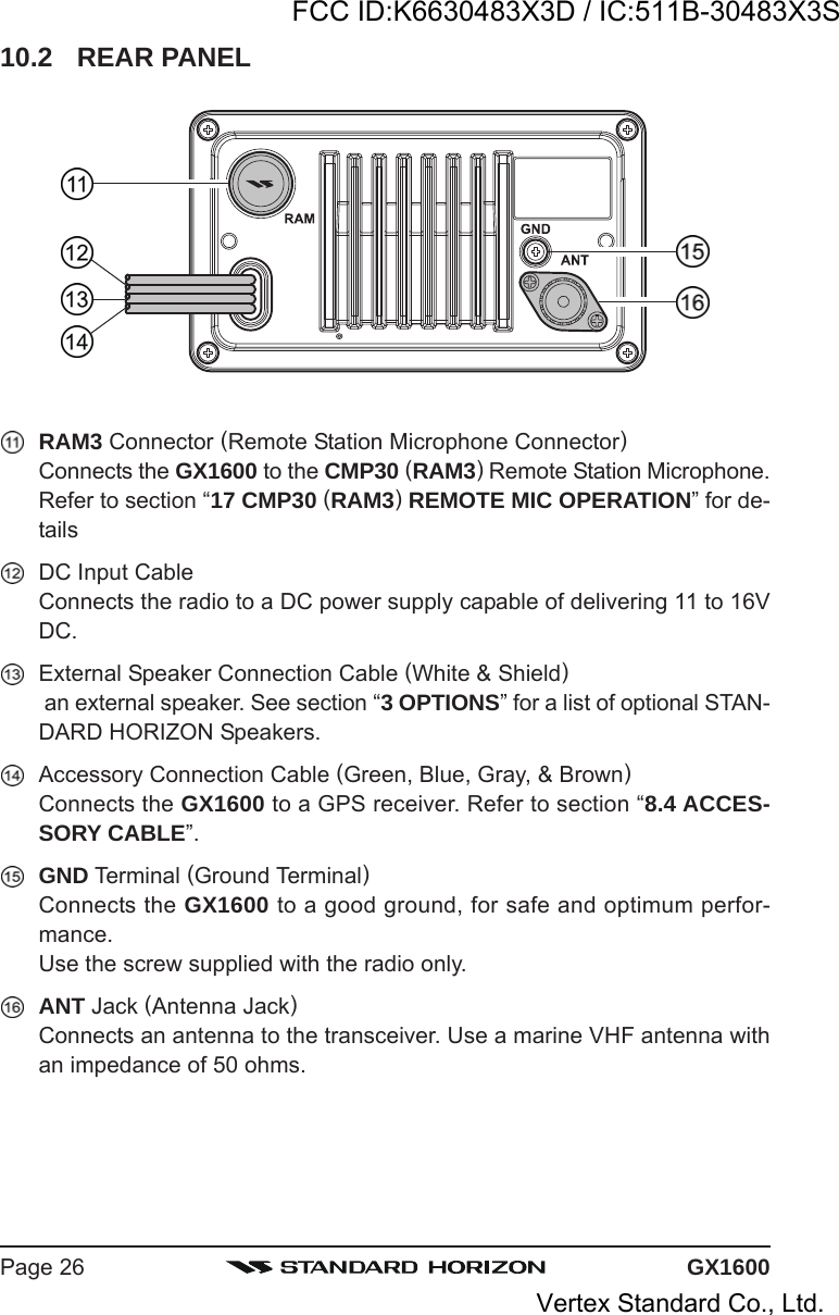
![GX1600Page 2410 CONTROLS AND INDICATORSNOTEThis section defines each control of the transceiver. See illustration atthe next page for location of controls. For detailed operating instructionsrefer to chapter 10 of this manual.10.1 FRONT PANEL/ KeyThe / key is used to select channels and to choose menu items(such as the DSC menu, Radio Setup and DSC Setup menu). The [UP()]/ [DOWN()] keys on the microphone can also be used to select channelsand menu items.SECONDARY USEWhile holding down the [SCAN] soft key and pressing / key, youcan confirm memory channels that have been programmed for scanning. KeyPress the key briefly to recall channel 16 from any channel location.Press and hold the key to recall channel 9. Pressing the keyagain reverts to the previous selected working channel. KeyTurns the transceiver on and off. To turn the transceiver on, press and holdthis key until the LCD turns on. To turn it off, press and hold this key untilthe LCD turns off. When the power is turned on, the transceiver is set tothe last-selected channel.FCC ID:K6630483X3D / IC:511B-30483X3SVertex Standard Co., Ltd.](https://usermanual.wiki/Yaesu-Musen/30483X3D.Users-Manual-1/User-Guide-1406710-Page-24.png)
![Page 25GX1600[DISTRESS] KeyUsed to send a DSC Distress Call. To send the distress call refer to section“11.3.1 Transmitting a DSC Distress Call.”VOL Knob (Volume Control Knob)Adjusts the audio volume level. Turn this knob clockwise to increase theaudio volume level.SECONDARY USEWhen in the Intercom mode, controls the listen volume. KeyPress this key to recall the user preset memory channels (shown as memorychannel number “0” - “9” on the display). Press the or key to select thedesired preset channel.Press and hold this key for two seconds to memorize the selected channelinto the preset memory. KeyPress the [CALL(MENU)] key to access the “DSC MENU”.SECONDARY USEPress and hold the [CALL(MENU)] key to access the “SETUP MENU”. KeyPress the key to toggle between 25 W (High) and 1 W (Low) power.When the TX output power is set to “Low” while the transceiver is on chan-nel 13 or 67, the output power will temporarily switch from “Low” to “High”power until the PTT is released. The key does not function on trans-mit inhibited and low power only channels.SQL Knob (Squelch Control)Adjusting this control clockwise, sets the point at which random noise onthe channel does not activate the audio circuits but a received signal does.This point is called the squelch threshold. Further adjustment of the squelchcontrol will degrade reception of wanted transmissions.Soft KeysThe 3 soft keys functions can be customized by the Setup Menu modesection “12.12 SOFT KEYS”. When one of the soft keys is pressed briefly,the functions will appear above each key on the display.FCC ID:K6630483X3D / IC:511B-30483X3SVertex Standard Co., Ltd.](https://usermanual.wiki/Yaesu-Musen/30483X3D.Users-Manual-1/User-Guide-1406710-Page-25.png)
![Page 29GX160011.4 SIMPLEX/DUPLEX CHANNEL USERefer to the VHF MARINE CHANNEL CHART (page121) for instructions onuse of simplex and duplex channels.NOTEAll channels are factory-programmed in accordance with FCC (USA),Industry Canada (Canada), and International regulations. Mode of op-eration cannot be altered from simplex to duplex or vice-versa.11.5 DISPLAY TYPEThe GX1600 display can be setup to show displays other than the default“NORMAL” VHF display by using the procedure below:1. Press and hold down the key until “Setup MenuSetup MenuSetup MenuSetup MenuSetup Menu”appears, then select “GENERAL SETUPGENERAL SETUPGENERAL SETUPGENERAL SETUPGENERAL SETUP” with the/ key.2. Press the [SELECT] soft key, then press the / key to select “DISPLAYDISPLAYDISPLAYDISPLAYDISPLAY”.3. Press the [SELECT] soft key.4. Press the / key to select desired screen“NORMALNORMALNORMALNORMALNORMAL”, “COMPASSCOMPASSCOMPASSCOMPASSCOMPASS”, or “WAYPOINTWAYPOINTWAYPOINTWAYPOINTWAYPOINT”.5. Press the [SELECT] soft key to store the selectedsetting.6. Press the [QUIT] soft key several times to return toradio operation.“NORMAL” DISPLAY “COMPASS” DISPLAY “WAYPOINT” DISPLAYFCC ID:K6630483X3D / IC:511B-30483X3SVertex Standard Co., Ltd.](https://usermanual.wiki/Yaesu-Musen/30483X3D.Users-Manual-1/User-Guide-1406710-Page-29.png)
![GX1600Page 3011.6 USA, CANADA, AND INTERNATIONAL MODETo change the channel group from USA to Canada or International:1. Press and hold down the key until “SetupSetupSetupSetupSetupMenuMenuMenuMenuMenu” appears.2. Press the / key to select “CH FUNC-CH FUNC-CH FUNC-CH FUNC-CH FUNC-TION SETUPTION SETUPTION SETUPTION SETUPTION SETUP”.2. Press the [SELECT] soft key, then press the/ key to select “CH GROUPCH GROUPCH GROUPCH GROUPCH GROUP”.3. Press the [SELECT] soft key.4. Press the / key to select desiredchannel group “USAUSAUSAUSAUSA”, “INTLINTLINTLINTLINTL”, or “CANADACANADACANADACANADACANADA”.5. Press the [ENT] soft key to store the selected set-ting.6. Press the [QUIT] soft key several times to return to radio operation.11.7 NOAA WEATHER CHANNELS1. To receive a NOAA weather channel, press the one of the Soft keys mo-mentarily, then press the [WX] soft key from any channel. The transceiverwill go to the last selected weather channel.2. Press the / key to select a different NOAA weather channel.3. To exit from the NOAA weather channels, press the one of the Soft keysmomentarily, then press the [WX] soft key. The transceiver returns to thechannel it was on prior to a weather channel.11.7.1 NOAA Weather AlertIn the event of extreme weather disturbances, such as storms and hurricanes,the NOAA (National Oceanic and Atmospheric Administration) sends a weatheralert accompanied by a 1050 Hz tone and subsequent weather report on oneof the NOAA weather channels. When the Weather Alert feature is enabled(see section “13.6 WEATHER ALERT”), the transceiver is capable of receiv-ing this alert if the following is performed:1. Program NOAA weather channels into the transceiver’s memory for scan-ning. Follow the same procedure as for regular channels under section“11.9.2 Programming Scan Memory.”2. Press the [SCAN] soft key once to start memory scanning.3. The programmed NOAA weather channels will be scanned along with theregular-programmed channels. However, scanning will not stop on a nor-mal weather broadcast unless a NOAA alert is received.4. When an alert is received on a NOAA weather channel, scanning will stop andthe transceiver will emit a loud beep to alert the user of a NOAA broadcast.FCC ID:K6630483X3D / IC:511B-30483X3SVertex Standard Co., Ltd.](https://usermanual.wiki/Yaesu-Musen/30483X3D.Users-Manual-1/User-Guide-1406710-Page-30.png)
![Page 31GX16005. Press the any key to stop the alert and receive the weather report.NOTEIf the key is not pressed the alert will sound for 5 minutes and then theweather report will be received.NOTEWhile listening to a weather channel, the radio can decode a weatheralert and sound an alarm.11.7.2 NOAA Weather Alert TestingNOAA tests the alert system ever Wednesday between 11AM and 1PM. Totest the GX1600’s NOAA Weather feature, on Wednesday between 11AM and1PM, setup as in section “11.7.1 NOAA Weather Alert” and confirm the alertis heard.11.8 DUAL WATCH (TO CHANNEL 16)Dual watch is used to scan two channels for communications. One channel isa normal VHF channel and the other is the priority, channel 16. When a signalis received on the normal channel the radio briefly switches between the nor-mal channel and Channel 16 to look for a transmission. If the radio receivescommunications on channel 16 the radio stops and listens to Channel 16 untilcommunication ends and then starts Dual watch scan again.1. Adjust the SQL knob until the background noise disappears.2. Select the channel you wish to dual watch to the priority channel 16.3. Press the one of the Soft keys, then press the [DW] soft key.The display will scan between CH16 and the chan-nel that was selected in step 2.If a transmission is received on the channel selectedin step 2, the GX1600 will dual watch to CH16.4. To stop Dual Watch, press the one of the soft keys, then press the [DW]soft key again.NOTEThe priority channel may be changed from Ch16 to another channel.Refer to section “14.5 PRIORITY CHANNEL”.FCC ID:K6630483X3D / IC:511B-30483X3SVertex Standard Co., Ltd.](https://usermanual.wiki/Yaesu-Musen/30483X3D.Users-Manual-1/User-Guide-1406710-Page-31.png)
![GX1600Page 3211.9 SCANNINGAllows the user to select the scan type from Memory scan or Priority scan.“Memory scan” scans the channels that were programmed into memory. “Pri-ority scan” scans the channels programmed in memory with the priority chan-nel.11.9.1 Selecting the Scan Type1. Press and hold down key until “SetupSetupSetupSetupSetupMenuMenuMenuMenuMenu” appears.2. Press the / key to select “CH FUNC-CH FUNC-CH FUNC-CH FUNC-CH FUNC-TION SETUPTION SETUPTION SETUPTION SETUPTION SETUP”.3. Press the [SELECT] soft key, then press the/ key to select “SCAN TYPESCAN TYPESCAN TYPESCAN TYPESCAN TYPE”.4. Press the [SELECT] soft key.5. Press the / key to select “PRIORITYPRIORITYPRIORITYPRIORITYPRIORITYSCANSCANSCANSCANSCAN” or “MEMORY SCANMEMORY SCANMEMORY SCANMEMORY SCANMEMORY SCAN”.6. Press the [SELECT] soft key to store the selectedsetting.7. Press the [QUIT] soft key several times to return to radio operation.11.9.2 Programming Scan Memory1. Press and hold down the key until “Setup MenuSetup MenuSetup MenuSetup MenuSetup Menu”appears.2. Press the / key to select “CH FUNCTIONCH FUNCTIONCH FUNCTIONCH FUNCTIONCH FUNCTIONSETUPSETUPSETUPSETUPSETUP”.3. Press the [SELECT] soft key, then press the / key to select “SCAN MEMORYSCAN MEMORYSCAN MEMORYSCAN MEMORYSCAN MEMORY”.4. Press the [SELECT] soft key.5. Press the / key to select a desired chan-nel to be scanned, the press the [ADD] soft key.“MEM” icon appears on the display, which indicatesthe channel has been selected to the scan channel.6. Repeat step 5 for all the desired channels to bescanned.7. To DELETE a channel from the list, select the chan-nel then press the [DELETE] soft key. “MEM” icondisappears from the display.8. When you have completed your selection, press the [QUIT] soft key sev-eral times to return to radio operation.FCC ID:K6630483X3D / IC:511B-30483X3SVertex Standard Co., Ltd.](https://usermanual.wiki/Yaesu-Musen/30483X3D.Users-Manual-1/User-Guide-1406710-Page-32.png)
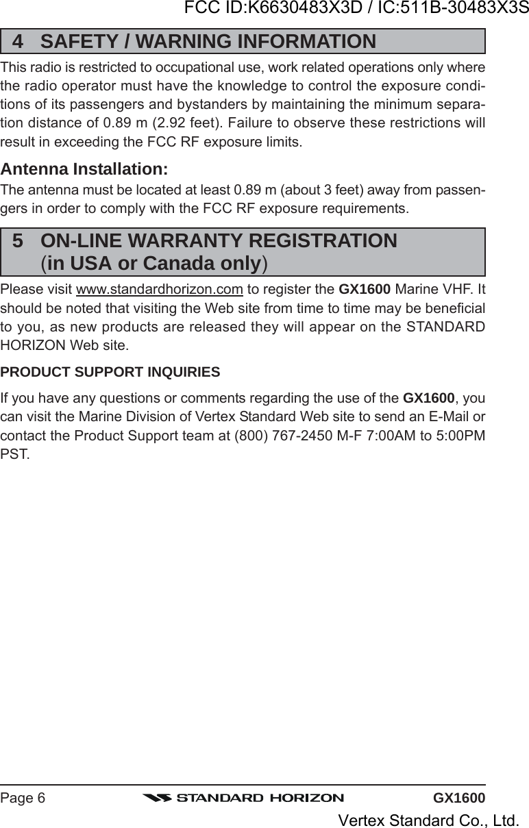
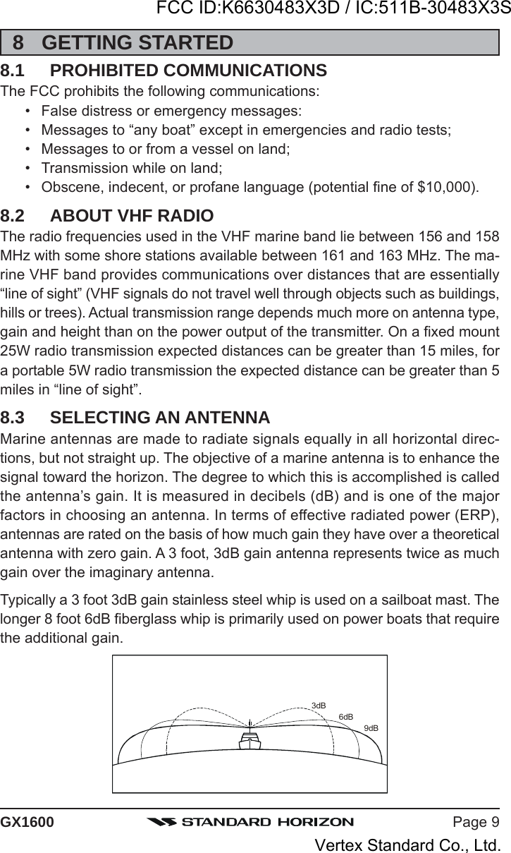
![Page 33GX160011.9.3 Memory Scanning (M-SCAN)1. Adjust the SQL knob until background noise disappears.2. Press the one of the Soft keys momentarily, then press the [SCAN] softkey. “M-SCAN” appears on the display. Scanning will proceed from thelowest to the highest programmed channel numberand Preset channel (described in the next chapter)and will stop on a channel when a transmission isreceived.3. The channel number will blink during reception.4. To stop scanning, press the key.11.9.4 Priority Scanning (P-SCAN)In the default setting, Channel 16 is set as the priority channel. You may changethe priority channel to the desired channel from Channel 16 by the Radio SetupMode, refer to section “14.5 PRIORITY CHANNEL”.1. Adjust the SQL knob until background noise disappears.2. Press the one of the Soft keys momentarily, thenpress the [SCAN] key. “P-SCANP-SCANP-SCANP-SCANP-SCAN” appears on the dis-play. Scanning will proceed between the memorizedchannels and Preset channel (described in nextchapter) and the priority channel. The priority channel will be scanned af-ter each programmed channel.3. To stop scanning, press the key.CH12CH09CH01ACH15CH18CH22ACH61ACH68ACH68ACH88AMEMORY SCAN (M-SCAN)Priority ChannelCH12CH09CH01ACH15CH18CH22ACH61ACH68ACH68ACH88APRIORITY SCAN (P-SCAN)FCC ID:K6630483X3D / IC:511B-30483X3SVertex Standard Co., Ltd.](https://usermanual.wiki/Yaesu-Musen/30483X3D.Users-Manual-1/User-Guide-1406710-Page-33.png)
![GX1600Page 3411.10 PRESET CHANNELS (0 ~ 9): INSTANT ACCESS10 Preset Channels can be programmed for instant access. Press the one ofthe Soft keys, then press the key. Pressing the activates the userassigned channel bank. If the key is pressed and no channels have beenassigned, an alert beep will be emitted from the speaker.11.10.1 Programming a Preset Channel1. Press the / key to select the channel to be programmed.2. Press and hold the key until the channel num-ber is blinking.3. Press the / key to select the desired Pre-set Channel (“SET 0SET 0SET 0SET 0SET 0” - “SET 9SET 9SET 9SET 9SET 9”) you wish to program.When recalls the Preset Channel which already pro-grammed, the operating channel number is shownat the right side of the Preset channel number.4. Press the [ADD] soft key momentarily to programthe channel into the Preset channel.5. Repeat steps 1 through 4 to program the desiredchannels into Preset Channels “0” ~ “9”.11.10.2 Operation1. Press the key to recall the Preset Channel.The “P SETP SETP SETP SETP SET” icon will appear at the channel number.2. Press the / key to select the desired Pre-set Channel (“0” ~ “9”). The Preset Channel num-ber appears (“P-SET0P-SET0P-SET0P-SET0P-SET0” - “P-SET9P-SET9P-SET9P-SET9P-SET9”) while selecting thePreset Channel.3. Press the key key again to return to the lastselected “regular” channel. The “P SETP SETP SETP SETP SET” icon will dis-appear from the display.11.10.3 Deleting a Preset Channel1. Recall the Preset Channel in accordance with the previous chapter.2. Press the / key to select the Preset Chan-nel to be delete.3. Press and hold the key until the channel num-ber is blinking.4. Press the [DELETE] soft key momentarily to deletethe channel from the Preset Channel.5. Repeat steps 2 through 4 to delete the desired chan-nels from Preset Channels “0” ~ “9”.6. To finish the deleting the Preset Channel, press the [QUIT] soft keyFCC ID:K6630483X3D / IC:511B-30483X3SVertex Standard Co., Ltd.](https://usermanual.wiki/Yaesu-Musen/30483X3D.Users-Manual-1/User-Guide-1406710-Page-34.png)
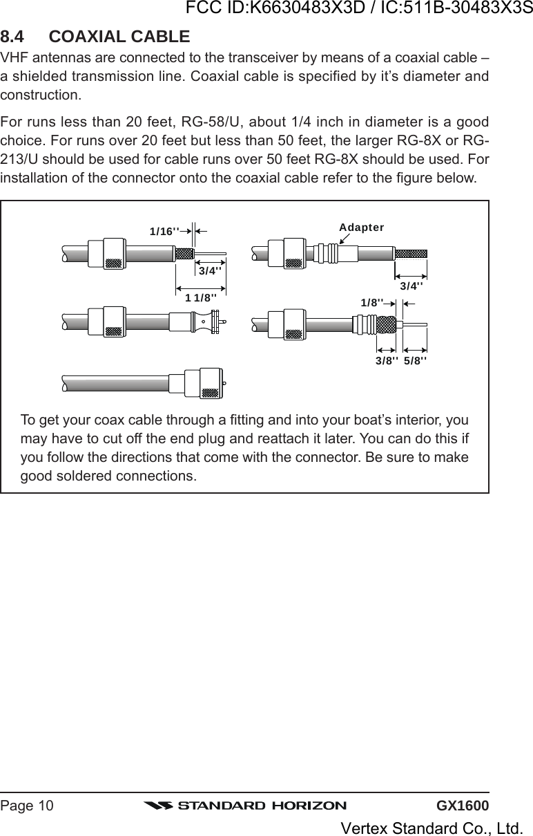
![Page 35GX160011.11 INTERCOM OPERATIONTo access the following Intercom functions one of the soft keys must be setupas IC. Refer to section “12.12 SOFT KEYS”.In addition an optional RAM3 must be connected to perform intercom func-tions between the radio and the RAM3.11.11.1 Communication1. Press the one of the Soft keys momentarily, thenpress the [IC] soft key to enable the intercom mode.Note: Depending on the programming of the [IC]soft key, the [NEXT] soft key may have to be pressedto see the [IC] soft key.2. When the intercom mode is enabled, “IntercomIntercomIntercomIntercomIntercom” is displayed on the radioand CMP30 (RAM3) Remote Station Microphone.3. Press the PTT switch on theradio. “TalkTalkTalkTalkTalk” will be shown onthe display.Note: A warning beep will beheard when the Radios PTTand CMP30 (RAM3) PTT arepushed at the same time.4. Speak slowly and clearly intothe microphone, hold the mi-crophone about 1/2 inch awayfrom your mouth.5. When finished, release the PTT switch.6. Press the [QUIT] soft key to exit intercom mode and revert to radio mode.10.12.2 CallingPress the [BELL] soft key when in intercom mode on either the radio or CMP30(RAM3) mic will produce a calling beep to the other station.(CMP30’s PTT switch is pressed)GX1600 RAM3(GX1600’s PTT switch is pressed)GX1600 RAM3FCC ID:K6630483X3D / IC:511B-30483X3SVertex Standard Co., Ltd.](https://usermanual.wiki/Yaesu-Musen/30483X3D.Users-Manual-1/User-Guide-1406710-Page-35.png)
![Page 37GX1600How can I obtain an MMSI assignment?In the USA, visit the following websites to register:http://www.boatus.com/mmsi/ orhttp://seatow.com/boating_safety/mmsi.aspIn the Canada, visithttp://www.ic.gc.ca/epic/site/smt-gst.nsf/en/sf01032e.html orhttp://www.usps.org/php/mmsi/rules.php12.2.2 Programming the MMSIWARNINGA user MMSI can be inputted only once. Therefore please be carefulnot to input the incorrect MMSI number. If you need to change theMMSI number after it has been entered, the radio will have to be returnedto Factory Service. Refer to the section “18.2 FACTORY SERVICE.”1. Press and hold down the key until the“Setup MenuSetup MenuSetup MenuSetup MenuSetup Menu” appears.2. Press the / key to select “MMSIMMSIMMSIMMSIMMSISETUPSETUPSETUPSETUPSETUP”.3. Press the [SELECT] soft key. (To cancel, press the[ENT] soft key.)4. Press the / key to select the firstnumber of your MMSI, then press the [ENT]soft key to step to the next number.5. Repeat step 4 to set your MMSI number (ninedigits).6. If a mistake was made entering in the MMSInumber, press the [BACK] soft key until thewrong number is selected, then press the/ key to correct the entry and press the[ENT] soft key.7. When finished programming the MMSI number, pressand hold the [ENT] soft key. The radio will ask you toinput the MMSI number again. Use steps 4 - 6 above.8. After the second number has been input, press and hold the CHANNELknob to store the MMSI.9. Press the [OK] soft key to return to radio operation.NOTETo view your MMSI after programming to ensure it is correct, performsteps 1~3. Look that the MMSI number shown on the display is correct.FCC ID:K6630483X3D / IC:511B-30483X3SVertex Standard Co., Ltd.](https://usermanual.wiki/Yaesu-Musen/30483X3D.Users-Manual-1/User-Guide-1406710-Page-37.png)
![GX1600Page 3812.3 DSC DISTRESS CALLThe GX1600 is capable of transmitting and receiving DSC Distress messagesto all DSC radios. The GX1600 may be connected to a GPS to also transmitthe Latitude, Longitude of the vessel.12.3.1 Transmitting a DSC Distress CallNOTETo be able to transmit a DSC distress call an MMSI number must beprogrammed, refer to section “11.2.2 Programming the MMSI.” In or-der for your ships location to be transmitted a GPS must be connectedto the GX1600, refer to section “8.4 ACCESSORY CABLE.”1. Lift the red spring loaded DISTRESS cover andpress the [DISTRESS] key. The “DISTRESS ALERTDISTRESS ALERTDISTRESS ALERTDISTRESS ALERTDISTRESS ALERT”menu will appear on the display.2. Press and hold the [DISTRESS] key. The radios dis-play will count down (3-2-1) and then transmit theDistress call. The backlight of the display and key-pad flashes while the radios display is countingdown.3. When the distress signal is sent, the transceiverwatches for a transmission between CH16 and CH70until an acknowledgment signal is received.4. If an acknowledgment is received, select channel16 and advise your distress situation.5. If no acknowledgment is received, the distress callis repeated in 4 minute intervals until a DSC ac-knowledgment is received.6. When a DSC Distress acknowledgment is received,a distress alarm sounds and channel 16 is auto-matically selected. The display shows the MMSI ofthe ship responding to your distress.RECEIVED ACK: acknowledgment signal is received.RECEIVED RLY: relay signal is received from another vessel or coast station.7. Press the PTT button and state your name, vessel name, number of per-sons on board and the distress situation, then say over. wait for a replyfrom the acknowledging ship.8. To turn off the Distress alarm until the radio retransmits the distress call,press the [16/9] key.FCC ID:K6630483X3D / IC:511B-30483X3SVertex Standard Co., Ltd.](https://usermanual.wiki/Yaesu-Musen/30483X3D.Users-Manual-1/User-Guide-1406710-Page-38.png)
![Page 39GX1600Transmitting a DSC Distress Alert with Nature of DistressThe GX2000/GX2100 is capable of transmitting a DSC Distress Alert with thefollowing “Nature of Distress” categories:Undesignated, Fire, Flooding, Collision, Grounding, Capsizing, Sinking,Adrift, Abandoning, Piracy, MOB1. Lift the red spring loaded DISTRESS cover andpress the [DISTRESS] key. The “DISTRESS ALERTDISTRESS ALERTDISTRESS ALERTDISTRESS ALERTDISTRESS ALERT”menu will appear on the display.2. Press the [NATURE] soft key, then press the / key to select the desired nature of distress cat-egory.3. Press and hold the [DISTRESS] key. The radios dis-play will count down (3-2-1) and then transmit theDistress call. The backlight of the display and key-pad flashes while the radios display is counting down.4. When the distress signal is sent, the transceiverwatches for a transmission between CH16 and CH70until an acknowledgment signal is received.5. If no acknowledgment is received, the DSC distresscall is repeated in 4 minute intervals until an acknowl-edgment is received.6. When a DSC Distress acknowledgment is received,a distress alarm sounds and channel 16 is auto-matically selected. The display shows the MMSI ofthe ship responding to your distress.RECEIVED ACK: acknowledgment signal is re-ceived.RECEIVED RLY ACK: relay acknowledgment signalis received from another ves-sel or coast station.7. Press the PTT button and state your name, vesselname, number of persons on board and the distresssituation, then say over. wait for a reply from the acknowledging ship.8. To turn off the Distress alarm until the radio retransmits the distress call,press the key.FCC ID:K6630483X3D / IC:511B-30483X3SVertex Standard Co., Ltd.](https://usermanual.wiki/Yaesu-Musen/30483X3D.Users-Manual-1/User-Guide-1406710-Page-39.png)
![GX1600Page 40Transmitting a DSC Distress Alert with Manual Position of InputWhen the GX1600 is not connected to a GPS receiver, you may input the lati-tude/longitude of your vessel manually and may send DSC Distress Alert.1. Lift the red spring loaded DISTRESS cover andpress the [DISTRESS] key. The “DISTRESS ALERTDISTRESS ALERTDISTRESS ALERTDISTRESS ALERTDISTRESS ALERT”menu will appear on the display.2. Press the [POS/TM] soft key.3. Enter the latitude/longitude of your vessel and yourlocal UTC time in the 24-hour notation. Press the/ key to select the number and press the[ENT] soft key to move the cursor to the next char-acter. You may backspace the cursor by pressingthe [BACK] soft key, if you make a mistake.4. When you have completed your selection, press andhold in the [ENT] soft key for two seconds to savethe setting.5. Press and hold the [DISTRESS] key. The radios dis-play will count down (3-2-1) and then transmit theDistress call. The backlight of the display and key-pad flashes while the radios display is countdown.6. When the distress signal is sent, the transceiver“shadow-watches” for a transmission between CH16and CH70 until an acknowledgment signal is received.7. If no acknowledgment is received, the distress callis repeated in 4 minute intervals until an acknowl-edgment is received.8. When a DSC Distress acknowledgment is received,a distress alarm sounds and channel 16 is auto-matically selected. The display shows the MMSI ofthe ship responding to your distress.RECEIVED ACK: acknowledgment signal is re-ceived.RECEIVED RLY ACK: relay acknowledgment signalis received from another vessel or coast station.9. Press the PTT button and state your name, vessel name, number of per-sons on board and the distress situation, then say over. wait for a replyfrom the acknowledging ship.10. To turn off the Distress alarm until the radio retransmits the distress call,press the key.FCC ID:K6630483X3D / IC:511B-30483X3SVertex Standard Co., Ltd.](https://usermanual.wiki/Yaesu-Musen/30483X3D.Users-Manual-1/User-Guide-1406710-Page-40.png)
![Page 41GX1600Pausing a DSC Distress CallAfter a DSC Distress call is transmitted, the DSC distress call is repeatedevery 4 minutes until the call is canceled by the user or until the radio is turnedon and off again. The GX1600 has provision to suspend (Pause) the retrans-mitting of the distress call by the procedure below.1. After the distress call is transmitted, the radio willshow the top display to the right.Looking at this display you will notice TX in: 02:25,this is the time when the radio will re-transmit theDSC distress call.2. To suspend re-transmitting the DSC call, press the[PAUSE] soft key.3. To resume counting down to transmit the DSC Dis-tress call, press the [RESUME] soft key.Cancel a DSC Distress CallIf a DSC Distress call was sent by error the GX1600 allows you to send amessage to other vessels to cancel the Distress Call that was made.Press the [CANCEL] soft key,then press [YES] soft key.12.3.2 Receiving a DSC Distress Call1. When a DSC Distress call is received, an emergency alarm sounds.2. Press any key to stop the alarm.3. The display shows the position of the vessel in dis-tress. To show additional information of the vesselin distress, press the key (refer to the seconddisplay).On the display you will notice 3 soft key selections.These selections are described below:ACCEPT: Press this key to accept the DSC distresscall and to switch to Channel 16.Note: If a key is not pressed for 30 seconds or longer the radio will auto-matically select Channel 16.PAUSE: Press this key to temporarily disable automatic switching to chan-nel 16.QUIT: Press this key to quit the automatic channel 16 switching and revertto the last selected working channel.FCC ID:K6630483X3D / IC:511B-30483X3SVertex Standard Co., Ltd.](https://usermanual.wiki/Yaesu-Musen/30483X3D.Users-Manual-1/User-Guide-1406710-Page-41.png)
![GX1600Page 424. Press the [WPT] soft key to enter the “Waypoint In-Waypoint In-Waypoint In-Waypoint In-Waypoint In-putputputputput” menu, then enter the desired waypoint name(up to 11 characters), described previously (selectthe letter/number by pressing the / key andmove the cursor by pressing the [ENT]/[BACK] softkey).6. The ID is the MMSI from the vessel in distress.7. When you are finished entering the waypoint name,press and hold the [ENT] soft key to replace thedisplay to the “WAYPOINT” Screen. The display in-dicates the distance and direction of the distressedvessel, and also the compass indicates the dis-tressed vessel by dot ().8. To return to the radio operation:1) Press and hold down the key until “Setup MenuSetup MenuSetup MenuSetup MenuSetup Menu” appears.2) Press the / key to select “DSC SETUPDSC SETUPDSC SETUPDSC SETUPDSC SETUP” menu.3) Press the [SELECT] soft key, then select “GENERAL SETUPGENERAL SETUPGENERAL SETUPGENERAL SETUPGENERAL SETUP” with the/ key.4) Press the [SELECT] soft key, then select “NORMALNORMALNORMALNORMALNORMAL” with the /key.5) Press the [SELECT] soft key to return to radio operation.NOTEYou must continue monitoring channel 16 as a coast station may re-quire assistance in the rescue attempt.FCC ID:K6630483X3D / IC:511B-30483X3SVertex Standard Co., Ltd.](https://usermanual.wiki/Yaesu-Musen/30483X3D.Users-Manual-1/User-Guide-1406710-Page-42.png)
![Page 43GX160012.4 ALL SHIPS CALLThe All Ships Call function allows contact to be established with DSC equippedvessels without having their MMSI in the individual calling directory. Also, pri-ority for the call can be designated as Urgency or Safety.URGENCY Call:This type of call is used when a vessel may not truly be indistress, but have a potential problem that may lead to a dis-tress situation. This call is the same as saying PAN PAN PANon channel 16.SAFETY Call: Used to transmit boating safety information to other vessels.This message usually contains information about an overdueboat, debris in the water, loss of a navigation aid or an impor-tant meteorological message. This call is the same as sayingSecurite, Securite, Securite.”12.4.1 Transmitting an All Ships Call1. Press the [CALL(MENU)] key. The “DSCDSCDSCDSCDSCMenuMenuMenuMenuMenu” will appear.2. Rotate the CHANNEL knob to select “AllAllAllAllAllSHIPSSHIPSSHIPSSHIPSSHIPS”.3. Press the [SELECT] soft key. (To cancel,press the [QUIT] soft key.)4. Press the / key to select the natureof call (“SAFETYSAFETYSAFETYSAFETYSAFETY” or “URGENCYURGENCYURGENCYURGENCYURGENCY”), then pressthe [SELECT] soft key.5. Press the / key to select the operatingchannel you want to communicate on, then pressthe [SELECT] soft key. If the channel you want touse is not listed, press the [MANUAL] soft key, thenpress the / key to select the operatingchannel you want to communicate on, then pressthe [SELECT] soft key.6. Press the [YES] soft key to transmit the selectedtype of all ships DSC call.7. After the All Ships Call is transmitted, the transceiverwill switch to the selected channel.8. Listen to the channel to make sure it is not busy,then key the microphone and say PAN PAN PAN or“Securite, Securite, Securite” depending on the pri-ority of the call.9. Press the [QUIT] soft key to exit the ALL ship call menu.FCC ID:K6630483X3D / IC:511B-30483X3SVertex Standard Co., Ltd.](https://usermanual.wiki/Yaesu-Musen/30483X3D.Users-Manual-1/User-Guide-1406710-Page-43.png)
![GX1600Page 4412.4.2 Receiving an All Ships Call1. When an all ships call is received, an emergencyalarm will sound.The display shows the MMSI of the vessel transmit-ting the All Ships Call and the radio will change tothe requested channel after 10 seconds.2. Press any key to stop the alarm.3. Monitor the requested channel until the ALL SHIPsvoice communication is completed.On the display you will notice 3 soft key selections.These selections are described below:ACCEPT: Press this key to accept the DSC All Shipcall and to switch to requested channel.Note: If a key is not pressed for 30 seconds or longer the radio will auto-matically change to the requested channel.PAUSE: Press this key to temporarily disable automatic switching to therequested channel.Note: In some cases automatically switching to a requested channel mightdisrupt import ongoing communications. This feature allows commercialusers to suspend channel switching and stay on the working channel se-lected before the All Ships call was received.QUIT: Press this key to quit the automatic channel switching and revert tothe last selected working channel.4. Press the [QUIT] soft key to return to the channel display.FCC ID:K6630483X3D / IC:511B-30483X3SVertex Standard Co., Ltd.](https://usermanual.wiki/Yaesu-Musen/30483X3D.Users-Manual-1/User-Guide-1406710-Page-44.png)
![Page 45GX160012.5 INDIVIDUAL CALLThis feature allows the GX1600 to contact another vessel with a DSC VHFradio and automatically switch the receiving radio to a desired communica-tions channel. This feature is similar to calling a vessel on CH16 and request-ing to go to another channel (switching to the channel is private between thetwo stations). Up to 80 Individual contacts may be programmed.12.5.1 Setting up the Individual / Position Call DirectoryThe GX1600 has a DSC directory that allows you to store a vessel or person’sname and the MMSI number associated with vessels you wish to transmitIndividual calls, Auto Polling, Position Request, and Position Report transmis-sions.To transmit an Individual call you must program this directory with informationof the persons you wish to call, similar to a cellular phones telephone directory.1. Press and hold down the key until “SetupSetupSetupSetupSetupMenuMenuMenuMenuMenu” appears.2. Press the / key to select “DSCDSCDSCDSCDSCSETUPSETUPSETUPSETUPSETUP” menu.3. Press the [SELECT] soft key, then select “INDI-INDI-INDI-INDI-INDI-VIDUAL DIRECTORYVIDUAL DIRECTORYVIDUAL DIRECTORYVIDUAL DIRECTORYVIDUAL DIRECTORY” with the / key.4. Press the [SELECT] soft key.5. Select “ADDADDADDADDADD” with the / key, thenpress the [SELECT] soft key.6. Press the / key to scroll through thefirst letter of the name of the vessel or person youwant to reference in the directory.7. Press the [ENT] soft key to store the first letter inthe name and step to the next letter to the right.8. Repeat step 6 and 7 until the name is complete.The name can consist of up to eleven characters, ifyou do not use all eleven characters press the [ENT]soft key to move to the next space. This methodcan also be used to enter a blank space in the name.If a mistake was made entering in the name repeatpressing the [BACK] soft key until the wrong character is selected, thenpress the / key to correct the entry.9. After the eleventh letter or space has been entered, press and hold the[ENT] soft key to advance to the MMSI (Maritime Mobile Service IdentityNumber) number entry.10. Press the / key to scroll through numbers, 0-9. To enter the de-FCC ID:K6630483X3D / IC:511B-30483X3SVertex Standard Co., Ltd.](https://usermanual.wiki/Yaesu-Musen/30483X3D.Users-Manual-1/User-Guide-1406710-Page-45.png)
![GX1600Page 46sired number and move one space to the right bypressing the [ENT] soft key. Repeat this procedureuntil all nine space of the MMSI number are entered.11. If a mistake was made entering in the MMSI numberrepeat pressing the [BACK] soft key until the wrong number is selected,then press the / key to correct the entry.12. To store the data entered, press and hold the [ENT] soft key.13. To enter another individual address, repeat steps 5 through 12.14. Press the [QUIT] soft key several times to return to radio operation.12.5.2 Setting up Individual ReplyThis menu item sets up the radio to automatically (default setting) or manuallyrespond to a DSC Individual call requesting you to switch to a working channelfor voice communications. When Manual is selected the MMSI of the callingvessel is shown allowing you to see who is calling. This function is similar tocaller id on a cellular phone.1. Press and hold down the key until “SetupSetupSetupSetupSetupMenuMenuMenuMenuMenu” appears.2. Press the / key to select “DSCDSCDSCDSCDSCSETUPSETUPSETUPSETUPSETUP” menu.3. Press the [SELECT] soft key, then select “IN-IN-IN-IN-IN-DIVIDUAL REPLYDIVIDUAL REPLYDIVIDUAL REPLYDIVIDUAL REPLYDIVIDUAL REPLY” with the / key.4. Press the [SELECT] soft key.5. Press the / key to select “AUTO-AUTO-AUTO-AUTO-AUTO-MATICMATICMATICMATICMATIC” or “MANUALMANUALMANUALMANUALMANUAL”.6. Press the [SELECT] soft key to store the selectedsetting.7. Press the [QUIT] soft key several times to return to radio operation.12.5.3 Enabling the Individual AcknowledgmentThe GX1150 can select either reply message “Able” (default) or “Unable” whenthe Individual Reply setting (described previous section) is set to “AUTOMATIC”.1. Press and hold down the key until “SetupSetupSetupSetupSetupMenuMenuMenuMenuMenu” appears.2. Press the / key to select “DSCDSCDSCDSCDSCSETUPSETUPSETUPSETUPSETUP” menu.3. Press the [SELECT] soft key, then select “IN-IN-IN-IN-IN-DIVIDUAL ACKDIVIDUAL ACKDIVIDUAL ACKDIVIDUAL ACKDIVIDUAL ACK” with the / key.4. Press the [SELECT] soft key.5. Press the / key to select “ABLE TOABLE TOABLE TOABLE TOABLE TOFCC ID:K6630483X3D / IC:511B-30483X3SVertex Standard Co., Ltd.](https://usermanual.wiki/Yaesu-Musen/30483X3D.Users-Manual-1/User-Guide-1406710-Page-46.png)
![Page 47GX1600COMPLYCOMPLYCOMPLYCOMPLYCOMPLY” or “UNABLEUNABLEUNABLEUNABLEUNABLE”.6. Press the [ENT] soft key to store the selected set-ting, then press the [QUIT] soft key several times toreturn to radio operation.12.5.4 Setting up Individual/Group Call RingerWhen a Individual Call or Group Call is received the radio will produce a ring-ing sound for 2 minutes. This selection allows the Individual Call ringer time tobe changed.1. Press and hold down the key until “SetupSetupSetupSetupSetupMenuMenuMenuMenuMenu” appears.2. Press the / key to select “DSCDSCDSCDSCDSCSETUPSETUPSETUPSETUPSETUP” menu.3. Press the [SELECT] soft key, then select “IN-IN-IN-IN-IN-DIVIDUAL RINGDIVIDUAL RINGDIVIDUAL RINGDIVIDUAL RINGDIVIDUAL RING” with the / key.4. Press the [SELECT] soft key.5. Press the / key to select ringing timeof a Individual Call.6. Press the [ENT] soft key to store the selected set-ting, then press the [QUIT] soft key several times toreturn to radio operation.The GX1600 has the capability to turn off the Individual and Group call ringer.1. Press and hold down the key until “SetupSetupSetupSetupSetupMenuMenuMenuMenuMenu” appears.2. Press the / key to select “DSCDSCDSCDSCDSCSETUPSETUPSETUPSETUPSETUP” menu.3. Press the [SELECT] soft key, then select “DSCDSCDSCDSCDSCBEEPBEEPBEEPBEEPBEEP” with the / key.4. Press the [SELECT] soft key.5. Press the / key to select “IndividualIndividualIndividualIndividualIndividual”if you wish to disable the Individual call ringer,or “GroupGroupGroupGroupGroup” if you wish to disable the Group call ringer,then press the [SELECT] soft key.6. Press the / key to select “OffOffOffOffOff”.7. Press the [ENT] soft key to store the selected setting.8. Press the [QUIT] soft key several times to return to radio operation.To re-enable the ringer tone, repeat the above procedure, pressing the / key to select “OnOnOnOnOn” in step “6” above.FCC ID:K6630483X3D / IC:511B-30483X3SVertex Standard Co., Ltd.](https://usermanual.wiki/Yaesu-Musen/30483X3D.Users-Manual-1/User-Guide-1406710-Page-47.png)
![GX1600Page 4812.5.5 Transmitting an Individual CallThis feature allows the user to contact another vessel with a DSC radio. Thisfeature is similar to calling a vessel on CH16 and requesting to go to anotherchannel.Pre-Programmed Calling1. Press the key. The “DSC MenuDSC MenuDSC MenuDSC MenuDSC Menu” will appear.2. Press the / key to select “INDIVIDUALINDIVIDUALINDIVIDUALINDIVIDUALINDIVIDUAL”. (Tocancel, press the [QUIT] soft key.)3. Press the [SELECT] soft key. The transceiver willbeep, and the “Last Individual Call” will appear.4. Press the / key to select the “Individual”you want to contact.5. Press the [SELECT] soft key, then press the / key to select the operating channel you wantto communicate on, then press the [SELECT] softkey. If the channel is not shown in the list, press the[MANUAL] soft key, then press the / keyto select the operating channel you want to com-municate on, then press the [SELECT] soft key.6. Press the [YES] soft key to transmit the individualDSC signal.7. When an individual call acknowledgment is received,the established channel is automatically changedto the channel which is selected on step 5 aboveand a ringing tone sounds.8. Press the [QUIT] soft key to listen to the channel tomake sure it is not busy, then press the microphone’sPTT switch and talk into the microphone to the othervessel.FCC ID:K6630483X3D / IC:511B-30483X3SVertex Standard Co., Ltd.](https://usermanual.wiki/Yaesu-Musen/30483X3D.Users-Manual-1/User-Guide-1406710-Page-48.png)
![Page 49GX1600Manual CallingYou may enter an MMSI number manually to contact without storing it in theIndividual Directory.1. Press the key. The “DSC MenuDSC MenuDSC MenuDSC MenuDSC Menu” menu will ap-pear.2. Press the / key to select “INDIVIDUALINDIVIDUALINDIVIDUALINDIVIDUALINDIVIDUAL”. (Tocancel, press the [QUIT] soft key.)3. Press the [SELECT] soft key. The transceiver willbeep, and the “Last Individual Call” will appear.4. Press the [NEW ID] soft key, then select “MANUALMANUALMANUALMANUALMANUAL”with the / key.5. Press the [SELECT] soft key.6. Press the / key to select the first numberof the MMSI which you want to contact, then pressthe [SELECT] soft key to step to the next number.7. Repeat step 6 to set the MMSI number (nine digits).8. If a mistake was made entering in the MMSI num-ber, repeat pressing the [BACK] key until the wrongnumber is selected, then press the / keyto correct the entry.9. When finished entering the MMSI number, press andhold the [SELECT] soft key.10. Press the [SELECT] soft key, then press the / key to select the operating channel you wantto communicate on, then press the [SELECT] softkey. If the channel is not shown in the list, press the[MANUAL] soft key, then press the / keyto select the operating channel you want to com-municate on, then press the [SELECT] soft key.11. Press the [YES] soft key to transmit the individualDSC signal.12. When an individual call acknowledgment is received,the established channel is automatically changedto the channel which is selected on step 5 aboveand a ringing tone sounds.13. Press the [QUIT] soft key to listen to the channel tomake sure it is not busy, then press the microphone’sPTT switch and talk into the microphone to the other vessel.FCC ID:K6630483X3D / IC:511B-30483X3SVertex Standard Co., Ltd.](https://usermanual.wiki/Yaesu-Musen/30483X3D.Users-Manual-1/User-Guide-1406710-Page-49.png)
![GX1600Page 5012.5.6 Receiving an Individual CallWhen a Individual DSC call is received, the radio will automatically respond(Default setting) to the calling ship, and switch to the requested channel forvoice communications. Refer to section “11.5.2 Setting up Individual Reply” tochange the reply to manual if you want to see who is calling before replying tothe call.1. When an individual call is received, an individualcall ringing alarm sounds.The radio automatically switches to the requestedchannel. The display shows the MMSI of the vesselcalling.2. Press any key to stop the alarm.3. Press the [QUIT] soft key to return to radio opera-tion4. Press the microphone’s PTT switch and talk into the microphone to theother vessel.FCC ID:K6630483X3D / IC:511B-30483X3SVertex Standard Co., Ltd.](https://usermanual.wiki/Yaesu-Musen/30483X3D.Users-Manual-1/User-Guide-1406710-Page-50.png)
![Page 51GX160012.6 DSC LOG OPERATIONThe GX1600 logs received distress calls and individual calls. The DSC Logfeature is similar to an answer machine where calls are recorded for reviewand a “ ” icon will appear on the radios display. The GX1600 can store up tothe latest 27 Distress, and up to the latest 64 other calls (Individual, Group, AllShip etc.).12.6.1 Reviewing and Relaying a Logged DSC Distress CallThe GX1600 radios allows logged DSC distress call to be reviewed and re-layed to a specific MMSI.1. Press the key. The “DSC menuDSC menuDSC menuDSC menuDSC menu” will ap-pear.2. Press the / key to select “DSC LOGDSC LOGDSC LOGDSC LOGDSC LOG”menu.3. Press the [SELECT] soft key, then press the / key to select “DISTRESS LOGDISTRESS LOGDISTRESS LOGDISTRESS LOGDISTRESS LOG”.4. Press the [SELECT] soft key, then press the/ key to select the station (name orMMSI number) you want to review and/or re-lay the distress call to other vessels.Note: When there is an unread received call, “ ”icon will appear behind the station name (or MMSInumber).5. Press the [SELECT] soft key, to review details forthe selected station.12.6.2 Reviewing a Logged All Ship or Individual CallReviewing a logged All ship or Individual call.1. Press the key. The “DSC MenuDSC MenuDSC MenuDSC MenuDSC Menu” will ap-pear.2. Press the / key to select “DSC LOGDSC LOGDSC LOGDSC LOGDSC LOG”menu.3. Press the [SELECT] soft key, then press the / key to select “OTHER CALL LOGOTHER CALL LOGOTHER CALL LOGOTHER CALL LOGOTHER CALL LOG”.4. Press the [SELECT] soft key, then press the / key to select the station (name or MMSI num-ber) you want to review and/or call back. When thereis an unread received call, “ ” icon will appear be-hind the station name (or MMSI number).FCC ID:K6630483X3D / IC:511B-30483X3SVertex Standard Co., Ltd.](https://usermanual.wiki/Yaesu-Musen/30483X3D.Users-Manual-1/User-Guide-1406710-Page-51.png)
![GX1600Page 525. Press the [SELECT] soft key, to review de-tails for the selected station.12.6.3 Deleting a Call from the “DSC LOG” Directory1. Press the key. The “DSC MenuDSC MenuDSC MenuDSC MenuDSC Menu” will ap-pear.2. Press the / key to select “DSC LOGDSC LOGDSC LOGDSC LOGDSC LOG”menu.3. Press the [SELECT] soft key, then press the / key to select “LOG DELETELOG DELETELOG DELETELOG DELETELOG DELETE” menu.4. Press the [SELECT] soft key, then press the/ key to select the category (“DIS-DIS-DIS-DIS-DIS-TRESS LOGTRESS LOGTRESS LOGTRESS LOGTRESS LOG” or “OTHER CALL LOGOTHER CALL LOGOTHER CALL LOGOTHER CALL LOGOTHER CALL LOG”) to be de-leted.5. Press the [SELECT] soft key.1) If you want to delete all stations at a time, selectthe “ALL LOG DELETEALL LOG DELETEALL LOG DELETEALL LOG DELETEALL LOG DELETE” with the / key, thenpress the [SELECT] soft key, then press the [OK]soft key. Press the [QUIT] soft key several timesto return to radio operation.2) If you want to delete oneof the logged stations, se-lect the “VIEW LOG LISTVIEW LOG LISTVIEW LOG LISTVIEW LOG LISTVIEW LOG LIST”with the / key,then press the [SELECT]soft key. Press the / key to select the sta-tion (name or MMSI num-ber) to be deleted, thenpress the [DELETE] soft key. The display willshow “Are your sure?Are your sure?Are your sure?Are your sure?Are your sure?” press the [OK] soft key.6. Press the [QUIT] soft key several times to return toradio operation.“VIEW LOG LIST”“ALL LOG DELETE”FCC ID:K6630483X3D / IC:511B-30483X3SVertex Standard Co., Ltd.](https://usermanual.wiki/Yaesu-Musen/30483X3D.Users-Manual-1/User-Guide-1406710-Page-52.png)
![Page 53GX160012.7 GROUP CALLThis feature allows the user to contact a group of specific vessels (examplemembers of a yacht club) using DSC radios with Group call function to auto-matically switch to a desired channel for voice communications. This functionis very useful for yacht clubs and vessels traveling together that want to collec-tively make announcements on a predetermined channel. Up to 32 GroupMMSI may be programmed.11.7.1 Setup a Group CallFor this function to operate, the same Group MMSI must be programmed intoall the DSC VHF radios within the group of vessels that will be using this fea-ture. To understand Group MMSI programming, first a Ship MMSI has to beunderstood.Ship MMSI: The first three digits called a MID (Mobile Identity Group) of a ShipMMSI denote the country the ship registered for a MMSI. The last 6 digits arespecific to the Ships ID.Ship MMSI Example: If your MMSI is “366123456”, “366” is MID which denotethe country and “123456” is your ships MMSI.Group MMSI:Group MMSI numbers are not assigned by the FCC or other organizationslicensed to assign ship MMSI numbers.The first digit of a Group MMSI is always set to “0” by International rules.All Standard Horizon radios are preset so when programming a GroupMMSI the first digit is set to “0”.The USCG recommends programming the MID of a ships MMSI into theSecond, Third and Fourth digits of the Group MMSI as it denotes the areathe ship is located in.The last 5 digits are decided upon by persons in the Group. This is animportant step as all radios in the Group must contain the same GroupMMSI so they can be contacted by each other. There is a chance thatanother group of vessels may program in the same Group MMSI. If thishappens, simply change one or more of the last 5 digits of the Group MMSI.1. Press and hold down the key until “Setup MenuSetup MenuSetup MenuSetup MenuSetup Menu”appears.2. Press the / key to select “DSC SETUPDSC SETUPDSC SETUPDSC SETUPDSC SETUP”menu.3. Press the [SELECT] soft key, then select “GROUPGROUPGROUPGROUPGROUPDIRECTORYDIRECTORYDIRECTORYDIRECTORYDIRECTORY” with the / key.4. Press the [SELECT] soft key, then select “ADDADDADDADDADD” withthe / key.FCC ID:K6630483X3D / IC:511B-30483X3SVertex Standard Co., Ltd.](https://usermanual.wiki/Yaesu-Musen/30483X3D.Users-Manual-1/User-Guide-1406710-Page-53.png)
![GX1600Page 545. Press the [SELECT] soft key.6. Press the / key to scroll through the firstletter of the name of the group you want to refer-ence in the directory.7. Press the [SELECT] soft key to store the first letterin the name and step to the next letter to the right.8. Repeat step 6 and 7 until the name is complete.The name can consist of up to eleven characters, ifyou do not use all eleven characters press the [SE-LECT] soft key to move to the next space. Thismethod can also be used to enter a blank space inthe name. If a mistake was made entering in thename repeat pressing the [BACK] soft key until thewrong character is selected, then press the / key to correct the entry.9. After the eleventh letter or space has been entered, press and hold the[SELECT] soft key to advance to the GROUP MMSI (Maritime Mobile Ser-vice Identity Number) number entry.10. Press the / key to select the second number of the MMSI (ninedigits: first digit permanently set to “0”) which youwant to contact, then press the [SELECT] soft keyto step to the next number. Repeat this procedureuntil all eight space of the MMSI number are en-tered.11. If a mistake was made entering in the MMSI number repeat pressing the[BACK] soft key until the wrong number is selected, then press the / key to correct the entry.12. To store the data entered, press and hold the [SELECT] soft key.13. To enter another group address, repeat steps 5 through 12.14. Press the [QUIT] soft key several times to return to radio operation.12.7.2 Transmitting a Group CallPre-Programmed Calling1. Press the key. The “DSC MenuDSC MenuDSC MenuDSC MenuDSC Menu” will appear.2. Press the / key to select “GROUPGROUPGROUPGROUPGROUP”. (To can-cel, press the [QUIT] key.)3. Press the [SELECT] soft key. The transceiver willbeep, and the “Last Group Call” will appear.4. Press the / key to select the “Group” youwant to contact.5. Press the [SELECT] soft key, then press the /FCC ID:K6630483X3D / IC:511B-30483X3SVertex Standard Co., Ltd.](https://usermanual.wiki/Yaesu-Musen/30483X3D.Users-Manual-1/User-Guide-1406710-Page-54.png)
![Page 55GX1600 key to select the operating channel youwant to communicate on, then press the [SE-LECT] soft key. If the channel you want is notshown, press the [MANUAL] soft key, thenpress the / key to select the oper-ating channel you want to communicate on,then press the [SELECT] soft key.6. Press the [YES] soft key to transmit the GroupCall signal.7. When the Group Call signal is sent, the dis-play will be as shown in the illustration at theright.8. After the Group Call is transmitted, all the ra-dios in the group will switch to the designatedchannel.9. Listen to the channel to make sure it is notbusy, then press the microphone’s PTT switchand call the other vessel you desire to communicate with.Manual CallingThis feature allows you to contact a group of vessels by entering in their GroupMMSI manually.1. Press the key. The “DSC MenuDSC MenuDSC MenuDSC MenuDSC Menu” will ap-pear.2. Press the / key to select “GROUPGROUPGROUPGROUPGROUP”.(To cancel, press the [QUIT] soft key.)3. Press the [SELECT] soft key. The transceiverwill beep, and the “Last Group Call” will ap-pear.4. Select “MANUALMANUALMANUALMANUALMANUAL” with the / key.5. Press the [SELECT] soft key.6. Press the / key to select the firstnumber of the MMSI (nine digits: first digit per-manently set to “0”) which you want to con-tact, then press the [SELECT] soft key to stepto the next number.7. Repeat step 6 to set the MMSI number.8. If a mistake was made entering in the MMSInumber, repeat pressing the [BACK] soft keyFCC ID:K6630483X3D / IC:511B-30483X3SVertex Standard Co., Ltd.](https://usermanual.wiki/Yaesu-Musen/30483X3D.Users-Manual-1/User-Guide-1406710-Page-55.png)
![GX1600Page 56until the wrong number is selected, then pressthe / key to correct the entry.9. When finished entering the MMSI number,press and hold the [SELECT] soft key.10. Press the / key to select the oper-ating channel you want to communicate on,then press the [SELECT] soft key. If the chan-nel you want is not shown, press the[MANUAL] soft key, then press the /key to select the operating channel you want to communicate on, thenpress the [SELECT] soft key.11. Press the [YES] soft key to transmit the Group Call signal.12. After the Group Call is transmitted, all the radios in the group will switch tothe designated channel.13. Listen to the channel to make sure it is not busy, then press the PTT buttonand talk into the microphone to the group of vessels.12.7.3 Receiving a Group Call1. When a group call is received, the GX1600 will pro-duce a ringing alarm sound.2. The display shows the GROUP MMSI number.3. Press the any key to stop the alarm.4. Monitor the channel for the person calling the Group for a message.On the display you will notice 3 soft key selections. These selections aredescribed below:ACCEPT: Press this key to accept the DSC Group Ship call and to switchto requested channel.Note: If a key is not pressed for 30 seconds or longer the radio will auto-matically change to the requested channel.PAUSE: Press this key to temporarily disable automatic switching to therequested channel.Note: In some cases automatically switching to a requested channel mightdisrupt import ongoing communications. This feature allows commercialusers to suspend channel switching and stay on the working channel se-lected before the Group call was received.QUIT: Press this key to quit the automatic channel switching and revert tothe last selected working channel.5. If you want to respond, monitor the channel to makesure it is clear, then press the microphone’s PTTswitch and talk into the microphone to the group ofvessels.FCC ID:K6630483X3D / IC:511B-30483X3SVertex Standard Co., Ltd.](https://usermanual.wiki/Yaesu-Musen/30483X3D.Users-Manual-1/User-Guide-1406710-Page-56.png)
![Page 57GX16006. Press the [QUIT] soft key to return to radio opera-tion.NOTEAfter a Group call is received, the time the call was made and the shipsMMSI or vessels name will appear on the display.FCC ID:K6630483X3D / IC:511B-30483X3SVertex Standard Co., Ltd.](https://usermanual.wiki/Yaesu-Musen/30483X3D.Users-Manual-1/User-Guide-1406710-Page-57.png)
![GX1600Page 5812.8 POSITION REQUESTAdvancements in DSC have made it possible to poll the location of anothervessel and show the position of that vessel on the display of the GX1600.Standard Horizon has taken this feature one step further, if any compatibleGPS chart plotter is connected to the GX1600, the polled position of the vesselis shown on the display of the GPS chart plotter making it easy to navigate tothe location of the polled vessel. This is a great feature for anyone wanting toknow the position of another vessel. For example your buddy that is catchingfish, or finding the location of a person you are cruising with.NOTEThe other vessel must have an operating GPS receiver connected to itsDSC radio and must not have its radio set not to deny position requests.(Refer the section “11.5 INDIVIDUAL CALL” to enter information intothe individual directory).11.8.1 Setting up a Position ReplyThe GX1600 can be set up to automatically (default setting) or manually sendyour position when requested by another vessel. This selection is important ifyou are concerned about someone polling the position of your vessel that youmay not want to. In the manual mode you will see the MMSI or persons nameshown on the display allowing you to choose to send your position to the re-questing vessel.1. Press and hold down the key until “Setup MenuSetup MenuSetup MenuSetup MenuSetup Menu”appears.2. Press the / key to select “DSC SETUPDSC SETUPDSC SETUPDSC SETUPDSC SETUP”menu.3. Press the [SELECT] soft key, then select “POSITIONPOSITIONPOSITIONPOSITIONPOSITIONREPLYREPLYREPLYREPLYREPLY” with the / key.4. Press the [SELECT] soft key, then select “AUTO-AUTO-AUTO-AUTO-AUTO-MATICMATICMATICMATICMATIC” or “MANUALMANUALMANUALMANUALMANUAL”. In “AUTOMATICAUTOMATICAUTOMATICAUTOMATICAUTOMATIC” mode, aftera DSC POS Request is received, the radio will au-tomatically transmit your vessels position. In“MANUALMANUALMANUALMANUALMANUAL” mode, the display of the GX1600 willshow who is requesting the position and the YESsoft key on radio has to be pressed to send yourposition to the requesting.5. Press the [ENT] soft key to store the selected set-ting.6. Press the [QUIT] soft key several times to return to radio operation.FCC ID:K6630483X3D / IC:511B-30483X3SVertex Standard Co., Ltd.](https://usermanual.wiki/Yaesu-Musen/30483X3D.Users-Manual-1/User-Guide-1406710-Page-58.png)
![Page 59GX160012.8.2 Setting up a Position Request RingerThe GX1600 has the capability to turn off the Position Request ringer.1. Press and hold down the key until “SetupSetupSetupSetupSetupMenuMenuMenuMenuMenu” appears.2. Press the / key to select “DSCDSCDSCDSCDSCSETUPSETUPSETUPSETUPSETUP” menu.3. Press the [SELECT] soft key, then select “DSCDSCDSCDSCDSCBEEPBEEPBEEPBEEPBEEP” with the / key.4. Press the [SELECT] soft key, then select “POSPOSPOSPOSPOSRequestRequestRequestRequestRequest” with the / key.5. Press the [ENT] soft key, then select “OffOffOffOffOff” withthe / key.6. Press the [ENT] soft key to store the selected set-ting.7. Press the [QUIT] soft key several times to return to radio operation.To re-enable the ringer tone, repeat the above procedure, pressing the / key to select “OnOnOnOnOn” in step “5” above.12.8.3 Transmitting a Position Request to Another VesselPre-Programmed Request1. Press the key. The “DSC MenuDSC MenuDSC MenuDSC MenuDSC Menu” will ap-pear.2. Press the / key to select “POS RE-POS RE-POS RE-POS RE-POS RE-QUESTQUESTQUESTQUESTQUEST”.3. Press the / key to select a namethat was stored in the Individual DSC direc-tory, then press the [SELECT] soft key.4. Press the [YES] soft key to transmit the Posi-tion Request DSC call.5. When the GX1600 receives the position from thepolled vessel it is shown on the radio displayand also transferred to a GPS Chart plotterwith NMEA DSC and DSE sentences.6. Press the [QUIT] soft key to return to radiooperation.NOTEIf the GX1600 does not receive a position data from the polled vessel,the display will show “NO POSITION DATA.”FCC ID:K6630483X3D / IC:511B-30483X3SVertex Standard Co., Ltd.](https://usermanual.wiki/Yaesu-Musen/30483X3D.Users-Manual-1/User-Guide-1406710-Page-59.png)