Yaesu Musen 30583X3D CLASS D DSC MARINE TRANSCEIVER User Manual GX1300 User s Manual
Yaesu Musen Co., Ltd. CLASS D DSC MARINE TRANSCEIVER GX1300 User s Manual
UserManual.wiki
>
Yaesu Musen
>
30583X3D User Manual
User Manual
Navigation menu
Upload a User Manual
Namespaces
Wiki Guide
HTML
PDF
Info
Views
User Manual
Discussion / Help
Navigation
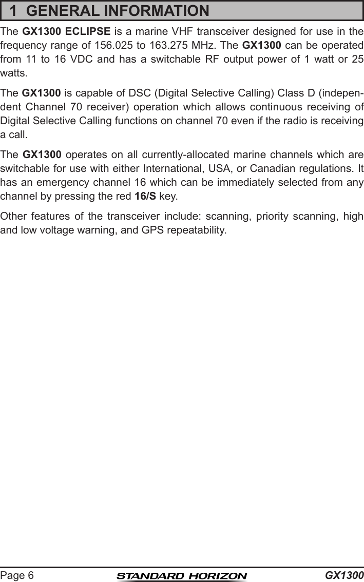
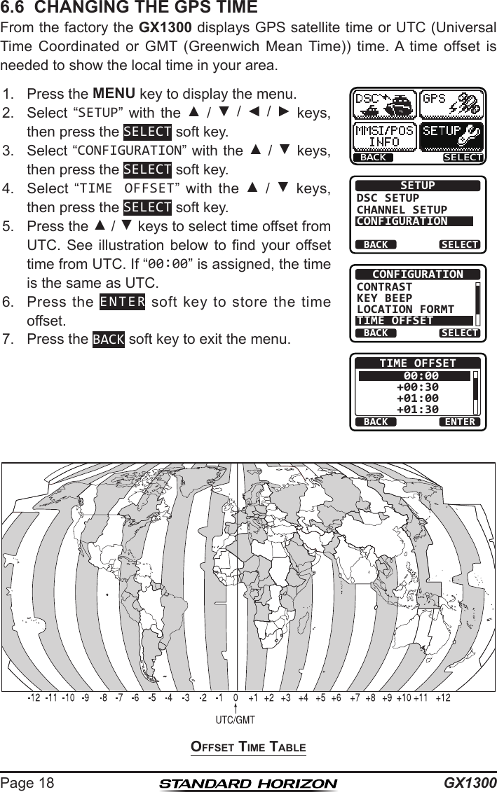
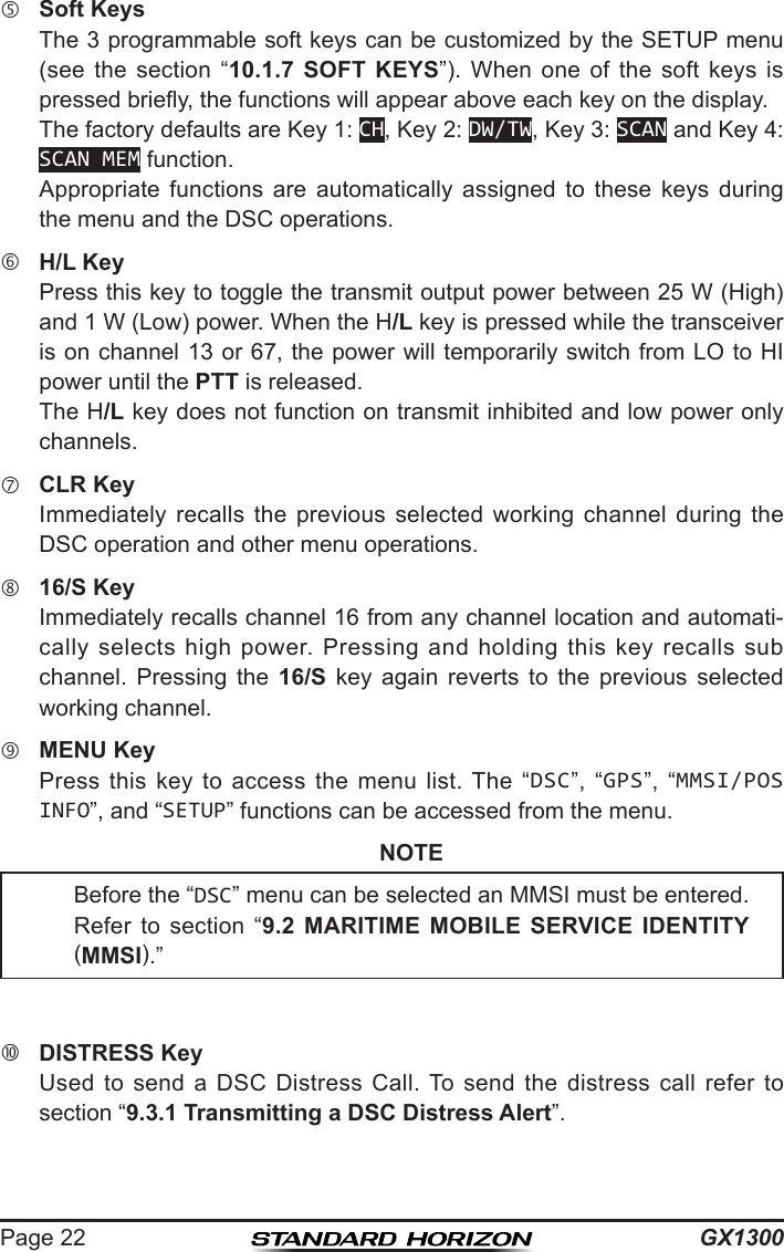
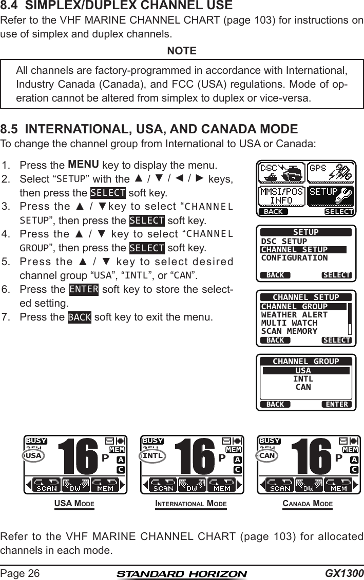
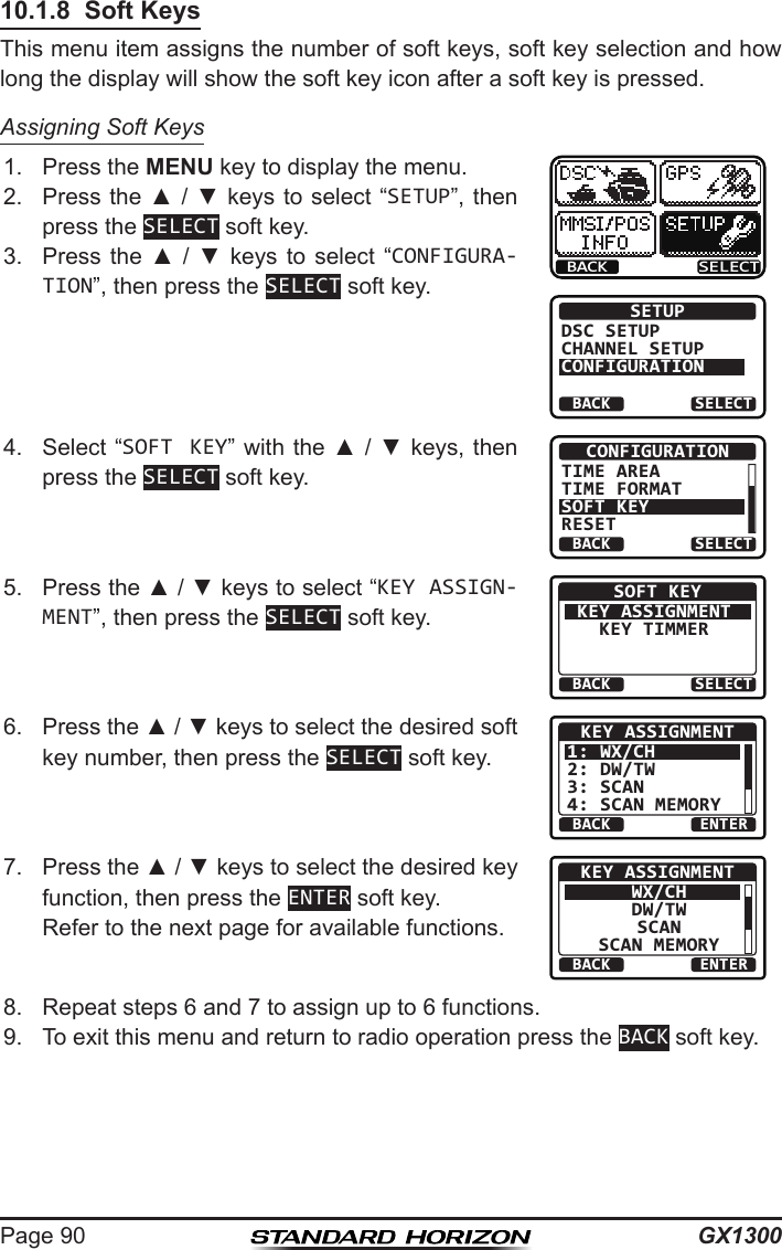
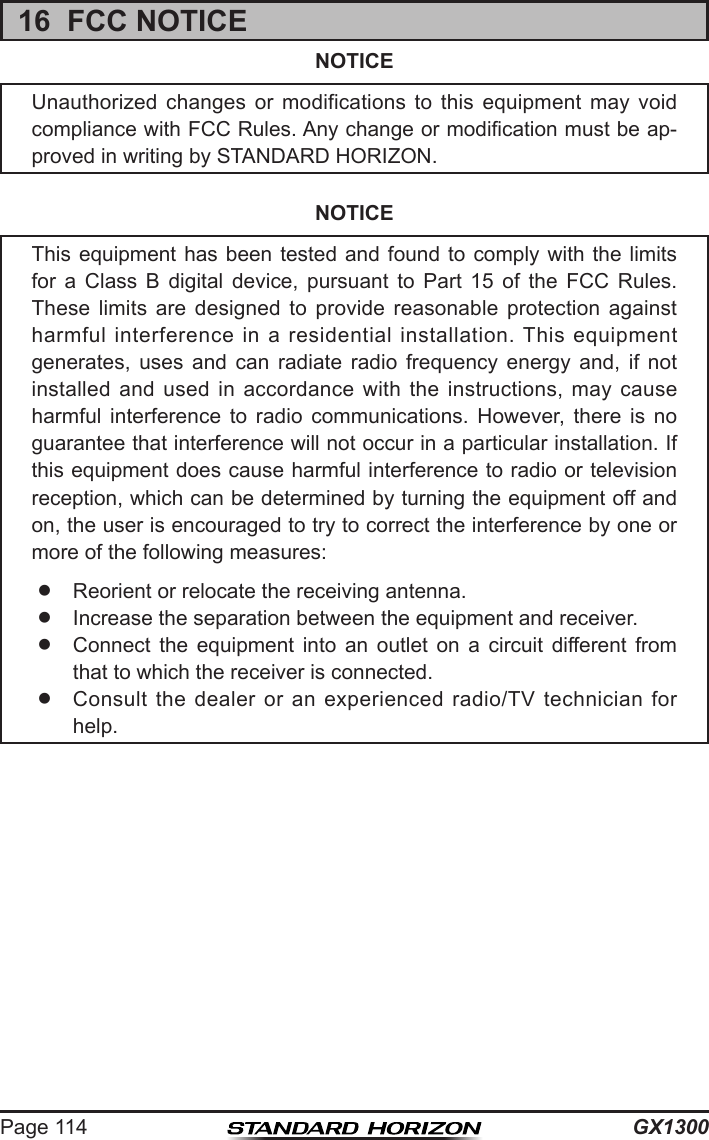
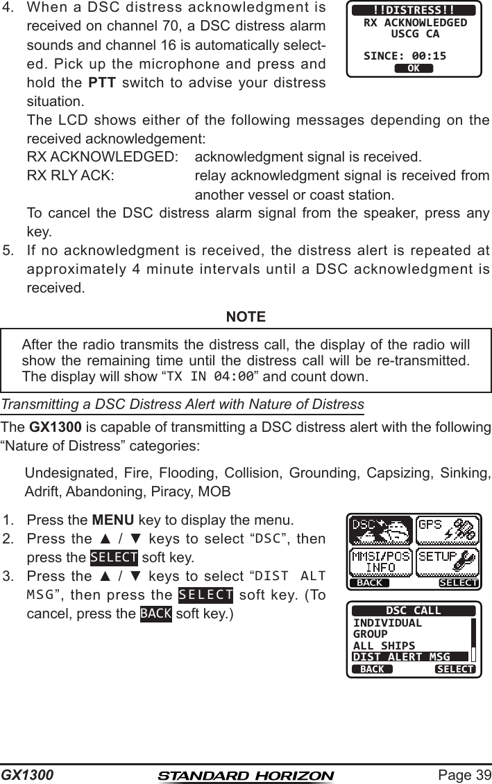
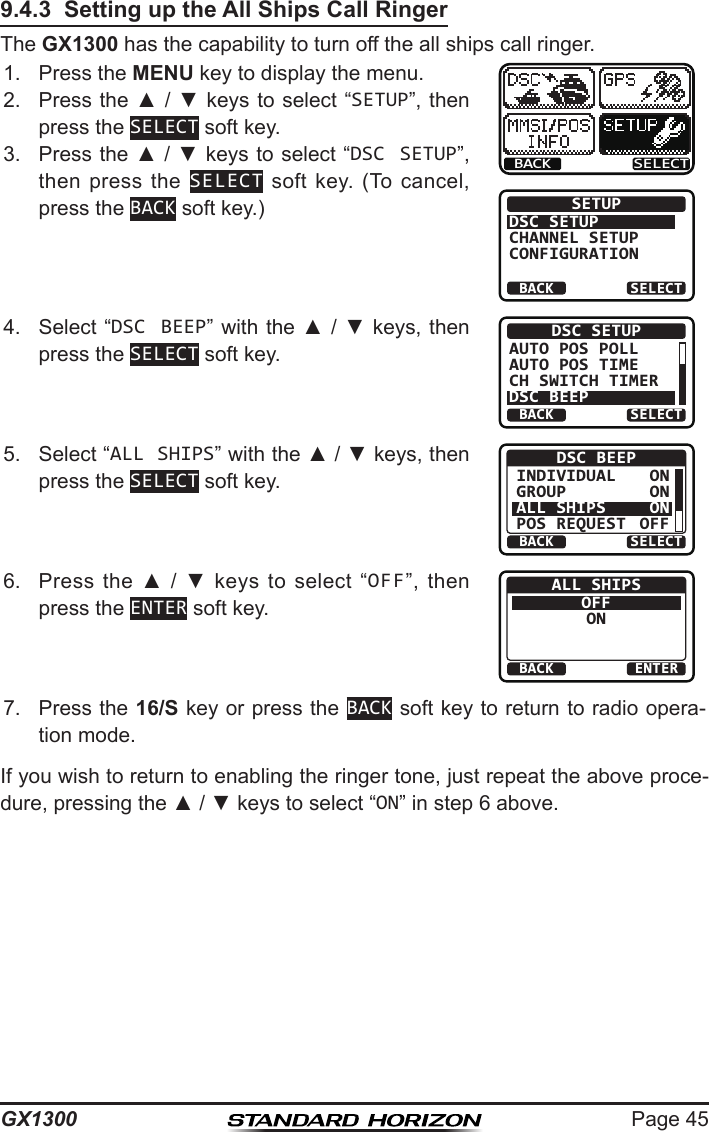
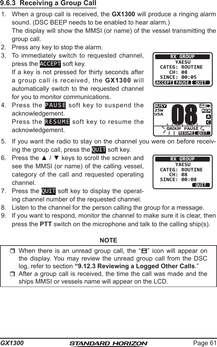
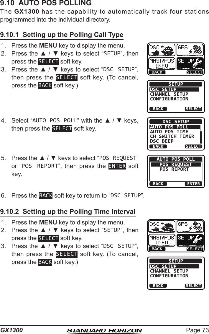
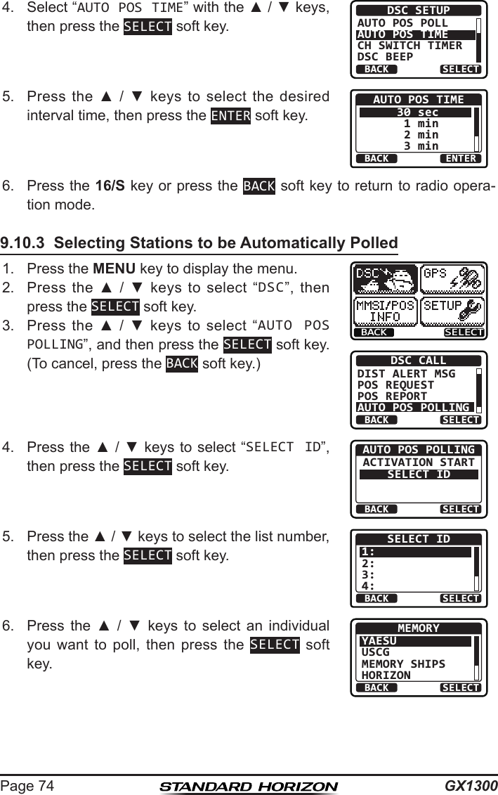
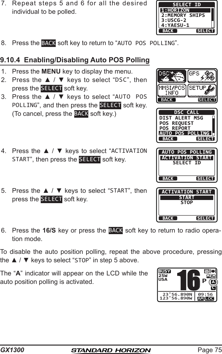
![GX1300Page 389.3 DSC DISTRESS ALERTThe GX1300 is capable of transmitting and receiving DSC distress messag-es to all DSC radios. The GX1300 may be connected to a GPS to also trans-mit the latitude and longitude of the vessel.NOTE9.3.1 Transmitting a DSC Distress AlertNOTEIn order for your vessel's location to be transmitted, either connect a GPS to the GX1300 (refer to section “6.4 ACCESSORY CABLE”) or manually input your position (refer to section “9.9 MANUAL INPUTTING OF THE GPS LOCATION”).Basic Operation1. Lift the red spring loaded DISTRESS cover, then press and hold the DISTRESS key. The “DISTRESS” screen will appear on the LCD and the radios display will count down (3sec 2sec 1sec) and then the distress alert will be transmitted. The backlight of the LCD and keypad ashes while the radios display is counting down.QUIT!!DISTRESS!!UNDESIGNATED[DISTRESS]Hold for 3 sec.!!DISTRESS!!UNDESIGNATED[ Transmitting ]!!DISTRESS!!UNDESIGNATED[Waiting for ACK]TX IN: 02:25PAUSEINFOCANCEL2. The GX1300 watches for an acknowledgment call on channel 70 or a voice call on channel 16 from another vessel.3. If an vessel responds to you on channel 16, pick up the microphone and press and hold the PTT switch to advise your distress situation.If a GPS with NMEA output is not connected to the radio, the GX1300 will beep 10 minutes after the radio is turned on and will continue to beep every 4 hours alerting to connect a GPS.To be able to transmit a DSC distress alert, an MMSI number must be programmed (refer to section “9.2.2 Programming the MMSI”).](https://usermanual.wiki/Yaesu-Musen/30583X3D/User-Guide-2532675-Page-38.png)
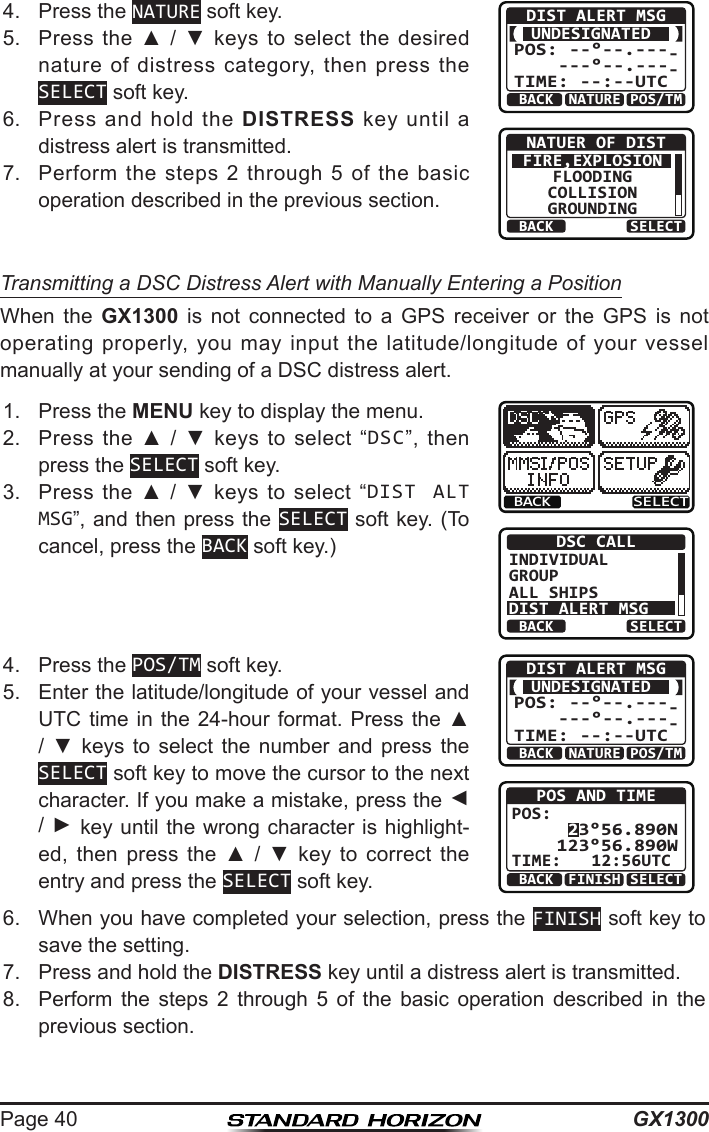
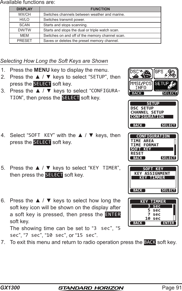
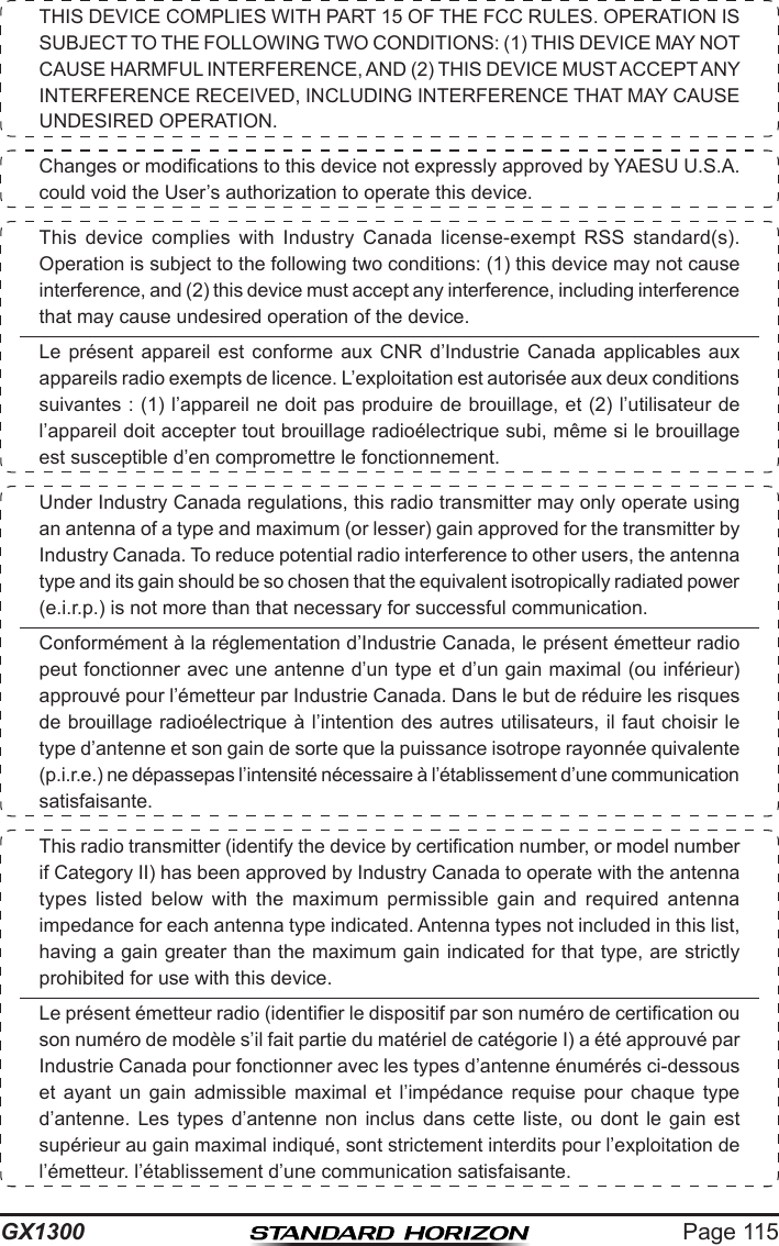
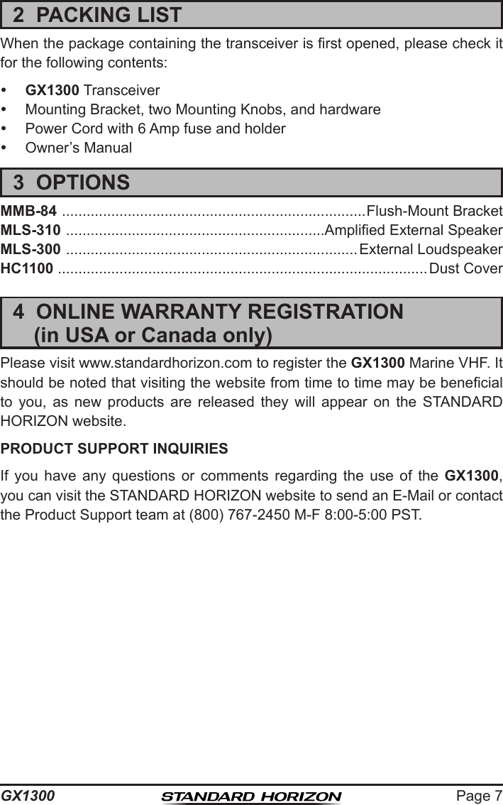
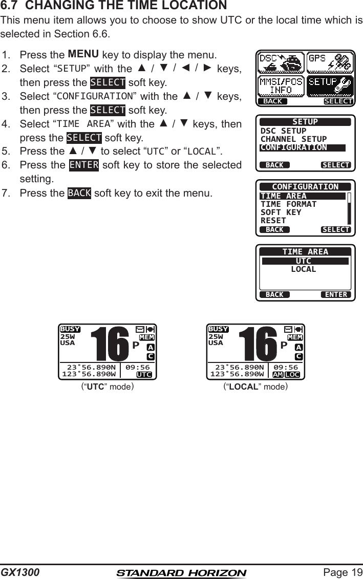
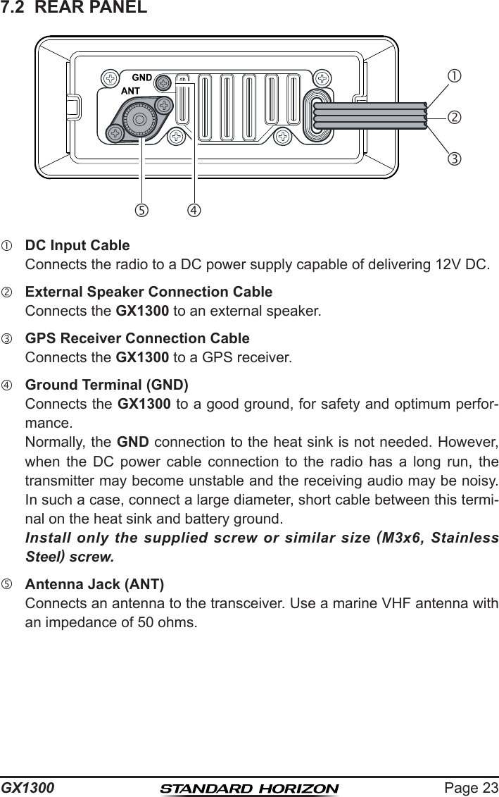
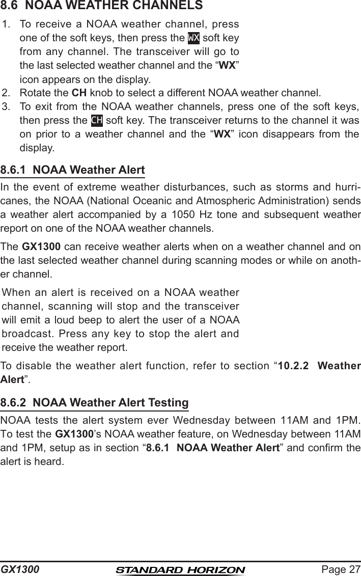
![Page 41GX1300Pausing a DSC Distress AlertAfter a DSC distress call is transmitted, it is repeated every 4 minutes until the call is canceled by the user or until the radio is turned off and on again. The GX1300 has provision to suspend (pause) the re-transmitting of the distress call by the procedure below.1. After the distress call is transmitted, the radio will show the display as on the right. Looking at this display you will notice “TX in 02:25”, this is the time when the radio will re-transmit the distress call.!!DISTRESS!!UNDESIGNATED[Waiting for ACK]TX IN: 02:25PAUSEINFOCANCEL!!DISTRESS!!UNDESIGNATEDRetransmissionis now pausing!TX IN: 02:25RESUMEINFOCANCEL2. To suspend re-transmitting the distress call, press the PAUSE soft key.3. To resume counting down to transmit the distress call, press the RESUME soft key.Canceling a DSC Distress AlertThe GX1300 has the capability to transmit a DSC distress cancel call by pressing the CANCEL soft key, then press the YES soft key.!!DISTRESS!!UNDESIGNATED[Waiting for ACK]TX IN: 02:25PAUSEINFOCANCEL!!DISTRESS!!UNDESIGNATEDDo you want tocancel a DIST?YESNO](https://usermanual.wiki/Yaesu-Musen/30583X3D/User-Guide-2532675-Page-41.png)
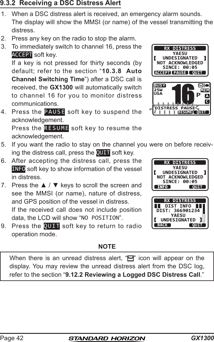
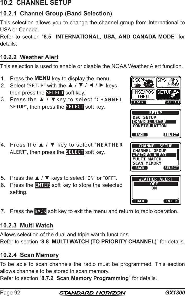
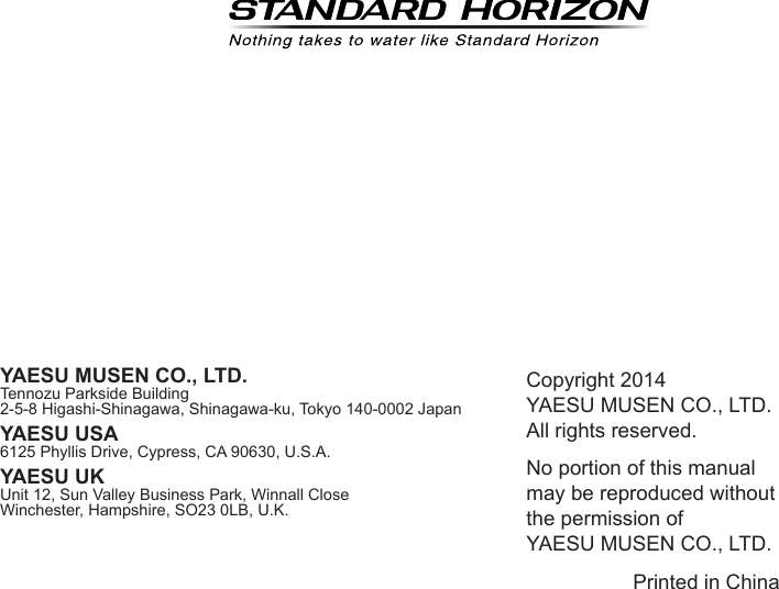
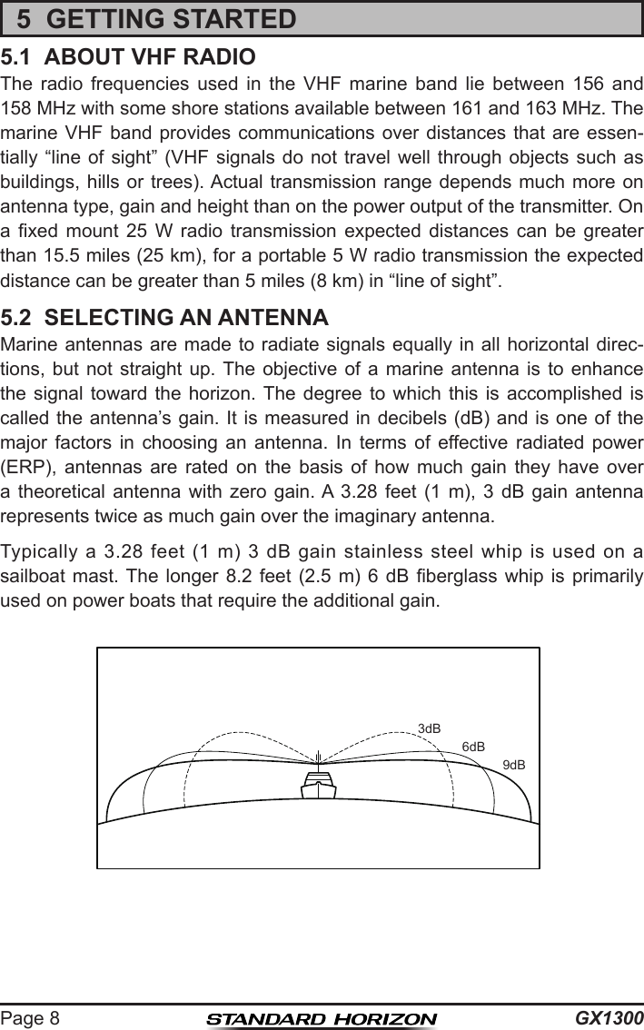
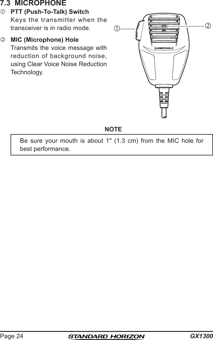
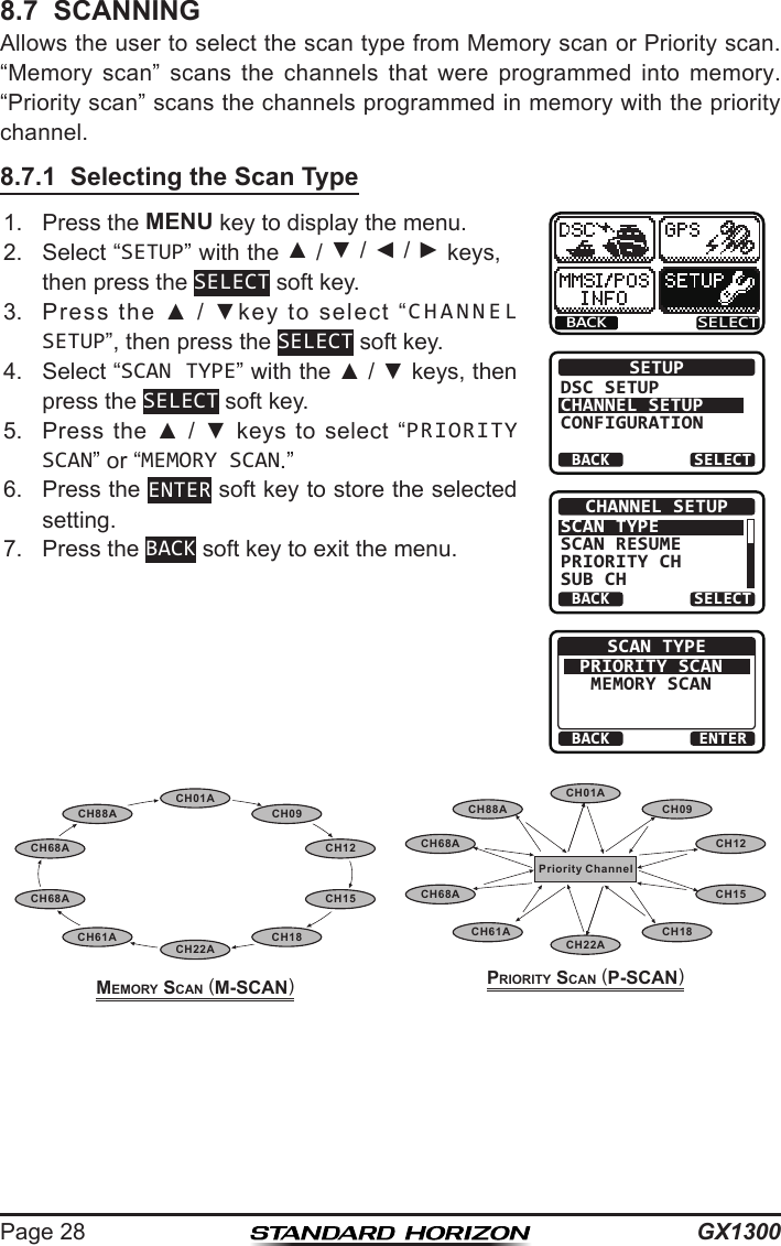
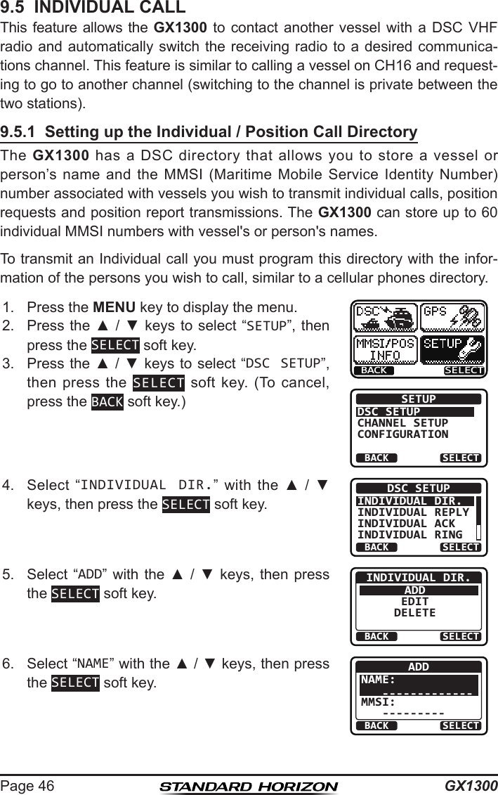
![GX1300Page 447. After the all ships call is transmitted, the trans-ceiver will switch to the channel which select-ed on the step 5 above, with no change of the display. To change the display, press the QUIT soft key.ALL SHIPS CATEG: SAFETY SINCE: 00:05 [ Transmitted ]QUIT8. Listen to the channel to make sure it is not busy, then key the micro-phone and say “PAN PAN, PAN PAN, PAN PAN” or “Securite, Securite, Securite” depending on the priority of the call. Say your call sign and announce the channel you wish to switch to for communications.9.4.2 Receiving an All Ships Call1. When an all ships call is received, an emergency alarm sounds. The display will show the MMSI (or name) of the vessel transmitting the all ships call.2. Press any key on the radio to stop the alarm.3. To immediately switch to requested channel, press the ACCEPT soft key. If a key is not pressed for thirty seconds (by default; refer to the section “10.3.8 Auto Channel Switching Time”) after an all ships call is received, the GX1300 will automatically switch to the requested channel for you to monitor communications.RX ALL SHIPS YAESUCATEG: SAFETY CH: 08SINCE: 00:05ACCEPT QUITPAUSEBUSYMEMACUSA25W08ALL SHIPS PAUSEQUITRESUME4. Press the PAUSE soft key to suspend the acknowledgement. Press the RESUME soft key to resume the acknowledgement.5. If you want the radio to stay on the channel you were on before receiv-ing the all ships call, press the QUIT soft key.6. Press the ▲ / ▼ keys to scroll the screen and see the MMSI (or name) of the calling vessel, category of the call and requested operating channel.RX ALL SHIPS YAESUCATEG: SAFETY CH: 08SINCE: 00:08ABLE QUITUNABLE7. Press the QUIT soft key to display the operat-ing channel number of the requested channel.8. Press the PTT switch on the microphone and talk to the calling vessel.](https://usermanual.wiki/Yaesu-Musen/30583X3D/User-Guide-2532675-Page-44.png)
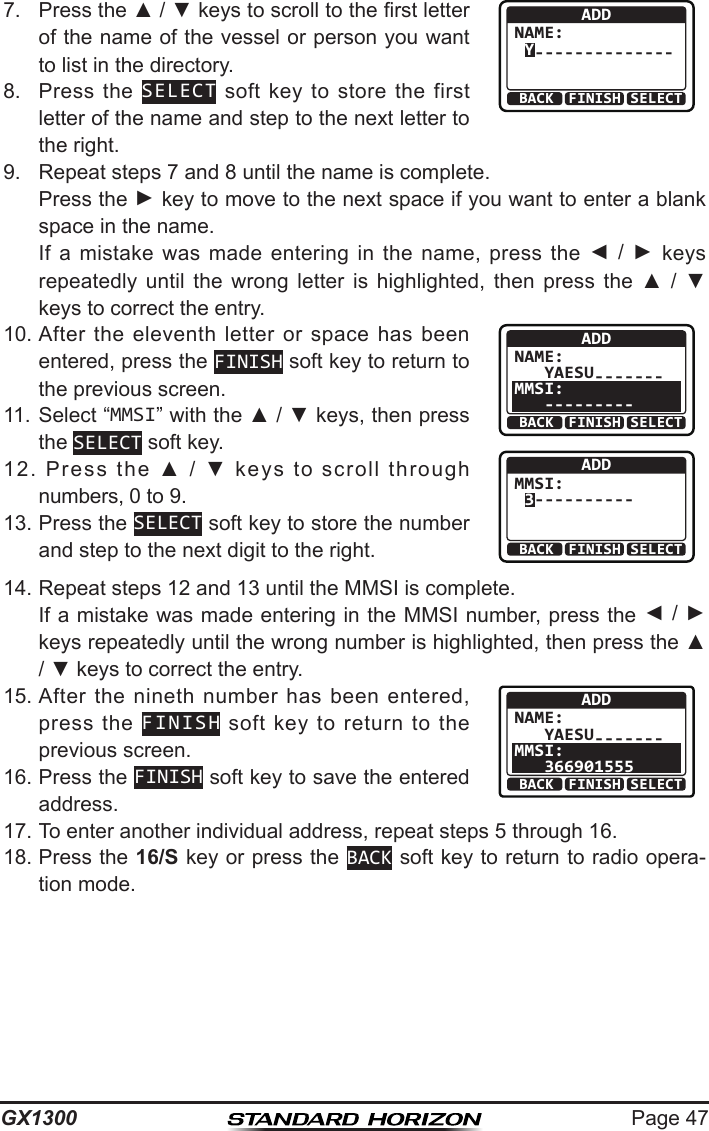
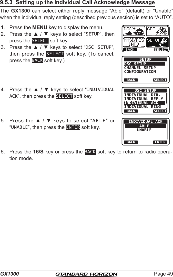
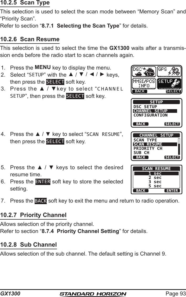
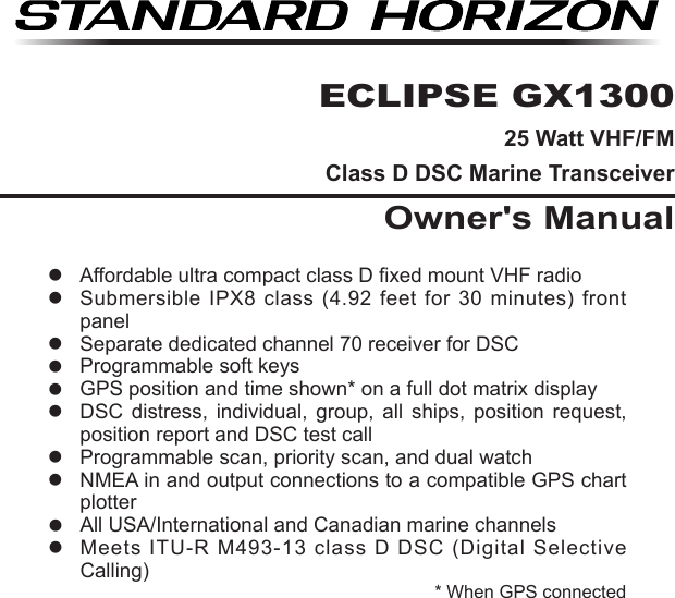
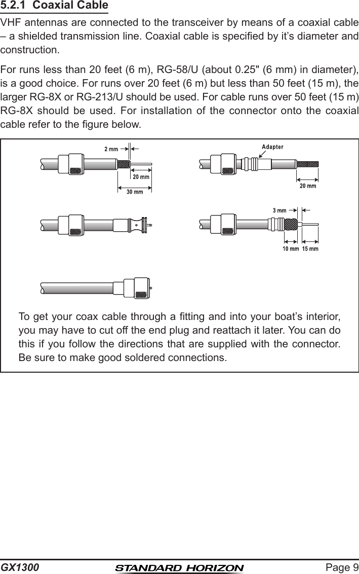
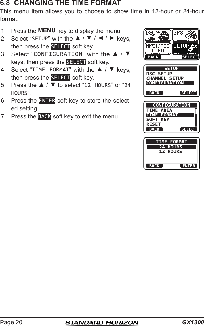
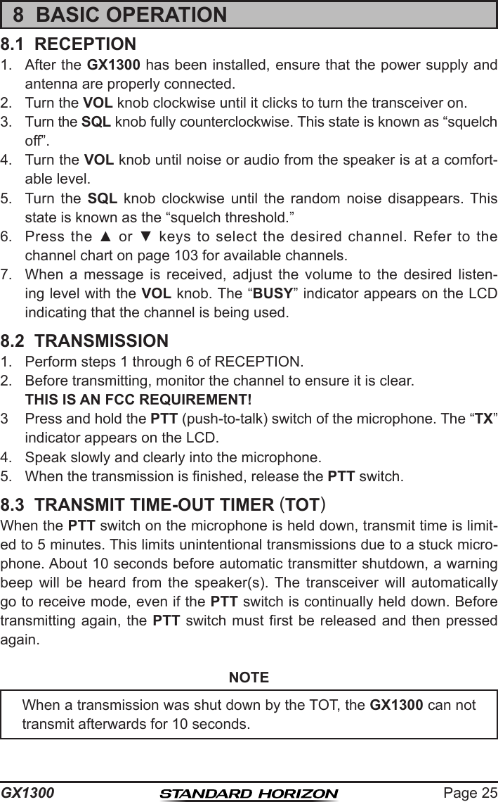
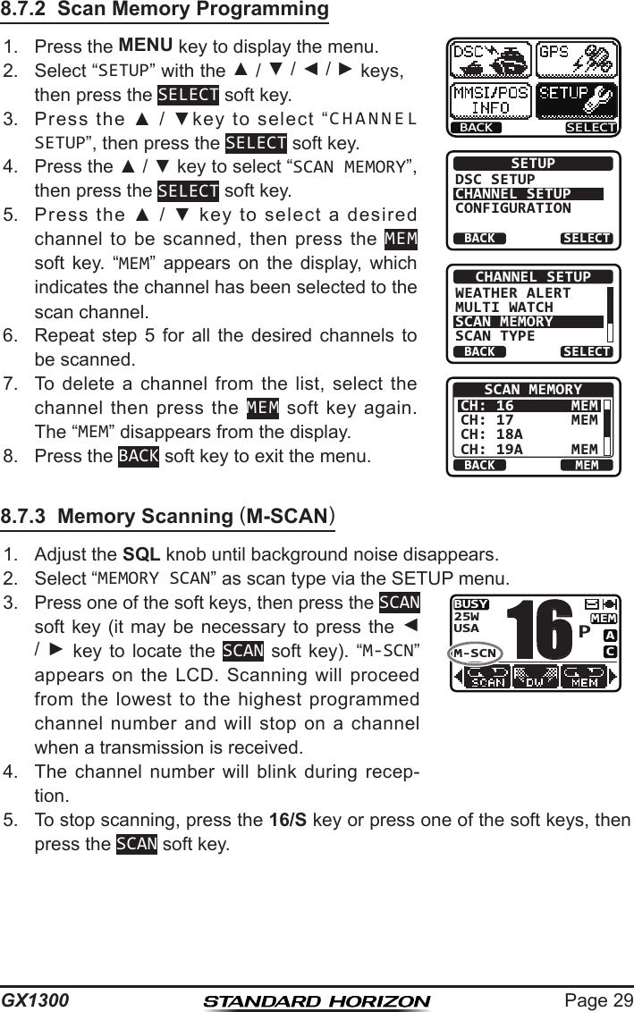
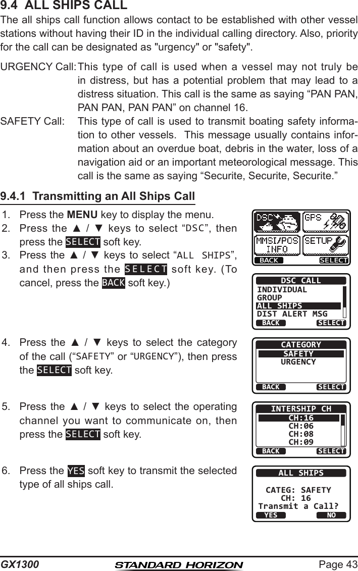
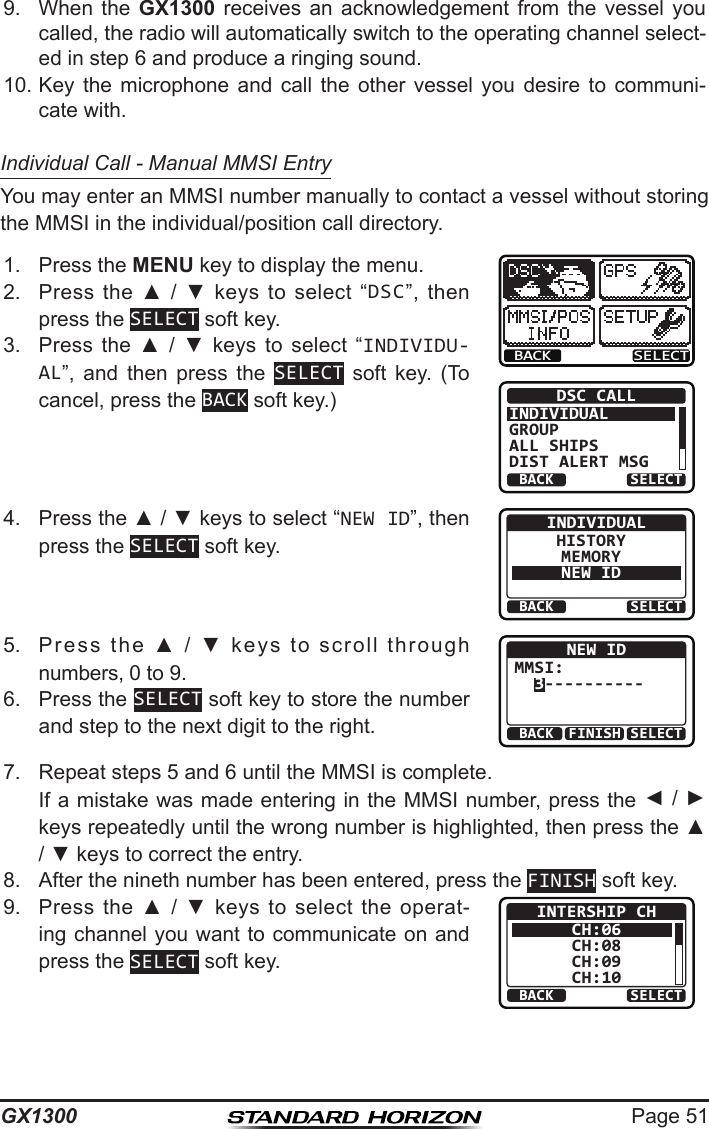
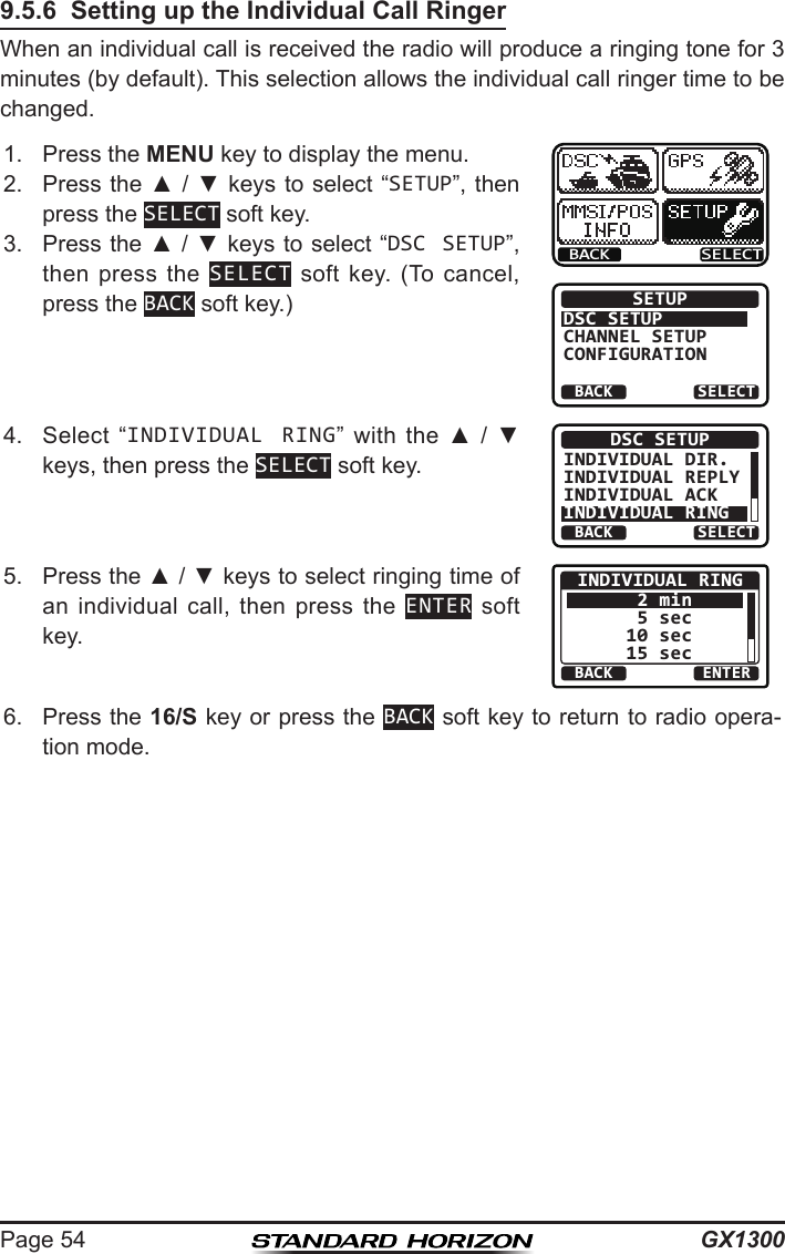
![GX1300Page 509.5.4 Transmitting an Individual CallThis feature allows you to contact another vessel, switch their radio to a requested working channel and ring like a telephone. This feature is similar to calling a vessel on CH16 and requesting to go to another channel.Individual Call from Individual / Position Call Directory1. Press the MENU key to display the menu.BACK SELECTBACK SELECTDSC CALLINDIVIDUALGROUPALL SHIPSDIST ALERT MSG2. Press the ▲ / ▼ keys to select “DSC”, then press the SELECT soft key.3. Press the ▲ / ▼ keys to select “INDIVIDU-AL”, and then press the SELECT soft key. (To cancel, press the BACK soft key.)4. Press the ▲ / ▼ keys to select “HISTORY” or “MEMORY”, then press the SELECT soft key.BACK SELECTINDIVIDUALHISTORYMEMORYNEW ID5. Press the ▲ / ▼ keys to select an individual you want to contact, then press the SELECT soft key.BACK SELECTMEMORYYAESUUSCGMEMORY SHIPSHORIZON6. Press the ▲ / ▼ keys to select the operat-ing channel you want to communicate on and press the SELECT soft key.BACK SELECTINTERSHIP CHCH:06CH:08CH:09CH:107. Press the YES soft key to transmit the individu-al DSC signal.INDIVIDUAL YAESUCATEG: ROUTINE CH: 08Transmit a Call?YESNO8. After an individual call is transmitted, if the reply signal is not received, “Waiting for ACK” is shown on the display which means the GX1300 is waiting for the vessel you called to send an acknowledgement. INDIVIDUAL YAESU CH: 08 SINCE: 00:05[Waiting for ACK]RESEND QUIT To transmit the call again, press the RESEND soft key.](https://usermanual.wiki/Yaesu-Musen/30583X3D/User-Guide-2532675-Page-50.png)
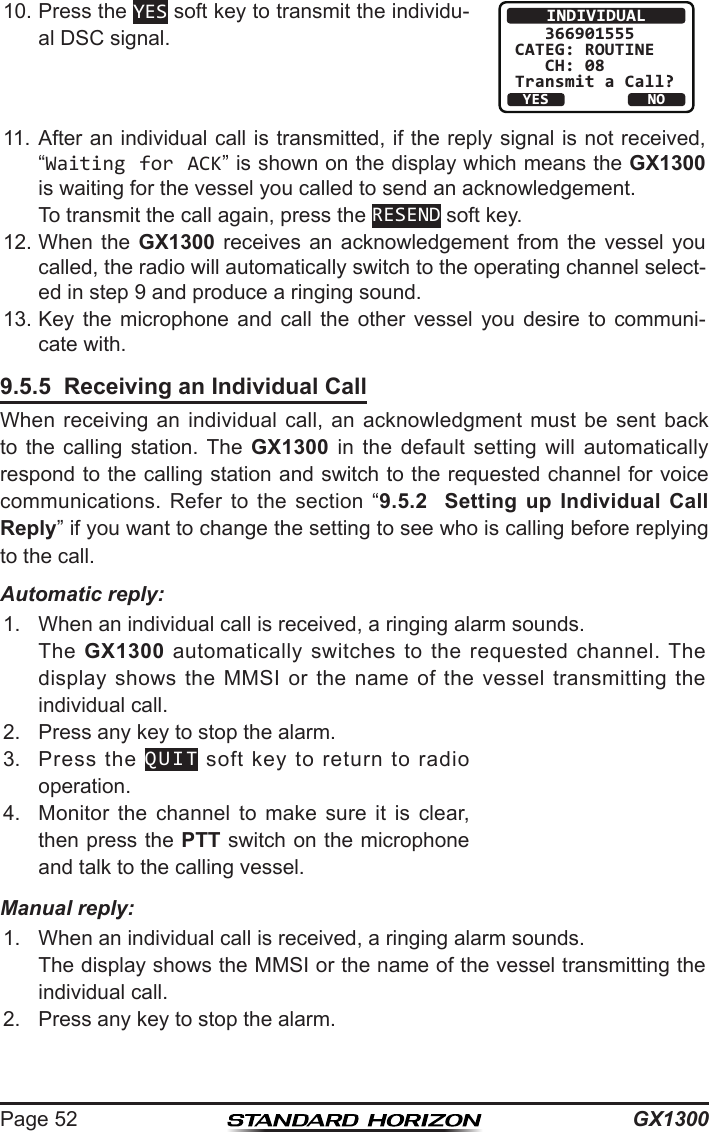
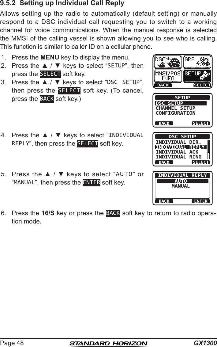
![Page 53GX13003. Press the ACCEPT soft key to accept the call. RX INDIVIDUAL YAESUCATEG: ROUTINE CH: 08SINCE: 00:05ACCEPT QUITPAUSE4. Press the PAUSE soft key to suspend the acknowledgement. Press the RESUME soft key to resume the acknowledgement.BUSYMEMACUSA25WINDIVIDUAL PAUSE08QUITRESUME5. After accepting the call, press the ABLE soft key to switch to the requested channel. (To inform that you cannot respond, press the UNABLE soft key.)RX INDIVIDUAL YAESUCATEG: ROUTINE CH: 08SINCE: 00:08ABLE QUITUNABLE6. Press the YES soft key to send an acknowl-edgement. Press the CHG CH soft key to change the channel for communication from the requested one.RX INDIVIDUAL YAESU CH: 08ABLE TO COMPLYTransmit a Call?YESNOCNG CHRX INDIVIDUAL YAESUCH: 08SINCE: 00:05[ Conncted ]RESEND QUIT7. After sending the acknowledgement, the GX1300 switches to the requested channel or to the channel selected in step 6, without changing the display. To change the display, press the QUIT soft key.8. Monitor the channel to make sure it is clear, then press the PTT switch on the microphone and talk to the calling vessel.](https://usermanual.wiki/Yaesu-Musen/30583X3D/User-Guide-2532675-Page-53.png)
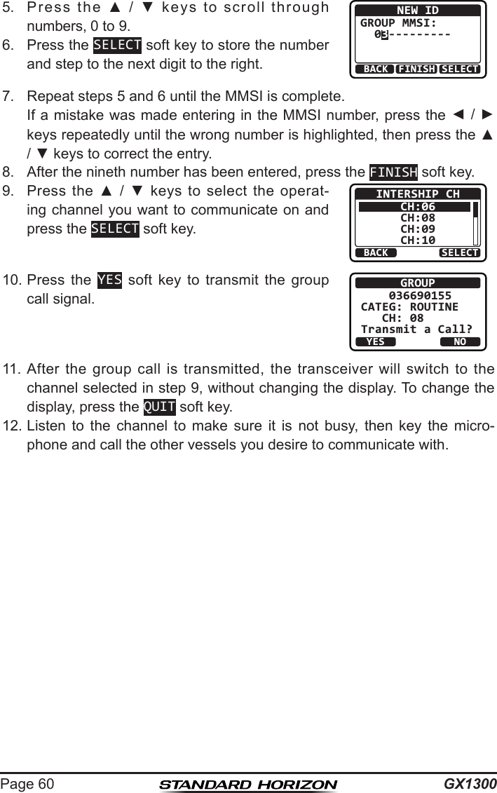
![Page 59GX13005. Press the ▲ / ▼ keys to select a group you want to contact, then press the SELECT soft key.BACK SELECTHISTORYYAESU GPUSCG GPMEMORY SHIPSHORIZON GP6. Press the ▲ / ▼ keys to select the operat-ing channel you want to communicate on and press the SELECT soft key.BACK SELECTINTERSHIP CHCH:06CH:08CH:09CH:107. Press the YES soft key to transmit the group call signal.GROUP YAESU GPCATEG: ROUTINE CH: 08Transmit a Call?YESNO8. After the group call is transmitted, the trans-ceiver will switch to the channel selected in step 6 above, without changing the display. To change the display, press the QUIT soft key.GROUP YAESU GP CH: 08SINCE: 00:05[ Transmitted ]QUIT9. Listen to the channel to make sure it is not busy, then key the micro-phone and call the other vessels you desire to communicate with.Group Call - Manual Group MMSI EntryYou may enter an MMSI number manually to contact a vessel without storing the MMSI in the Group Call Directory.1. Press the MENU key to display the menu.BACK SELECTBACK SELECTDSC CALLINDIVIDUALGROUPALL SHIPSDIST ALERT MSG2. Press the ▲ / ▼ keys to select “DSC”, then press the SELECT soft key.3. Press the ▲ / ▼ keys to select “INDIVIDU-AL”, and then press the SELECT soft key. (To cancel, press the BACK soft key.)4. Press the ▲ / ▼ keys to select “NEW ID”, then press the SELECT soft key.BACK SELECTGROUPHISTORYMEMORYNEW ID](https://usermanual.wiki/Yaesu-Musen/30583X3D/User-Guide-2532675-Page-59.png)
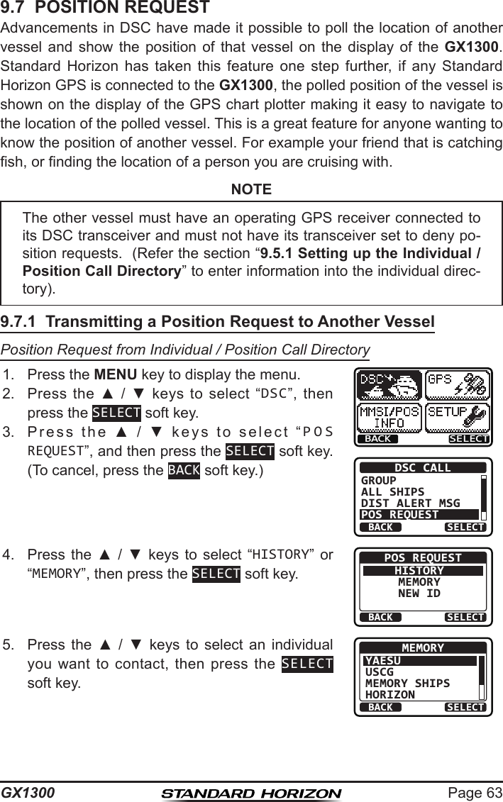
![GX1300Page 646. Press the YES soft key to transmit the position request call.POS REQUEST YAESUCATEG: SAFETY Transmit a Call?YESNO7. If the GX1300 does not receive a reply, the display will be as shown in the illustration on the right. To send again, press the RESEND soft key.POS REQUEST YAESU CATEG: SAFETY SINCE: 00:05[Waiting for ACK]RESEND QUIT8. When the GX1300 receives the position from the polled vessel, the GX1300 will produce a ringing alarm sound and the position from the polled vessel is sent to a GPS chart plotter via NMEA 0183. (DSC BEEP needs to be enabled to hear alarm.) Press any key to stop the alarm.9. Press the INFO soft key to show the position data transferred from the polled vessel on the display.RX POS REPLYYAESU POS ACKNOWLEDGED SINCE: 00:05QUITINFO10. Press the ▲ / ▼ keys to change the display to view the received data. POS INFO POS: 23°56.890N 123°56.890WTIME: 12:56 UTCRX POS REPLYBACK QUITBACKRX POS REPLYQUIT 123°56.890W TIME: 12:56 UTC DST: 29.8NM BRG: 270°T11. To exit from position request display, press the QUIT soft key.sNOTEIf the GX1300 does not receive position data from the polled vessel, the LCD will show “NO POSITION DATA”. POS INFO POS: --°--.---_ ---°--.---_TIME: --:--RX POS REPLYBACK QUIT](https://usermanual.wiki/Yaesu-Musen/30583X3D/User-Guide-2532675-Page-64.png)
![Page 65GX1300Position Request - Manual MMSI EntryYou may enter an MMSI number manually to contact a vessel without storing the MMSI in the individual/position call directory.1. Press the MENU key to display the menu.BACK SELECTBACK SELECTDSC CALLGROUPALL SHIPSDIST ALERT MSGPOS REQUEST2. Press the ▲ / ▼ keys to select “DSC”, then press the SELECT soft key.3. Press the ▲ / ▼ keys to select “POS REQUEST”, and then press the SELECT soft key. (To cancel, press the BACK soft key.)4. Press the ▲ / ▼ keys to select “NEW ID”, then press the SELECT soft key.BACK SELECTPOS REQUESTHISTORYMEMORYNEW ID5. Press the ▲ / ▼ keys to scroll through numbers, 0 to 9.BACK SELECTFINISHNEW IDMMSI: 3----------6. Press the SELECT soft key to store the number and step to the next digit to the right.7. Repeat steps 5 and 6 until the MMSI is complete. If a mistake was made entering in the MMSI number, press the ◄ / ► keys repeatedly until the wrong number is highlighted, then press the ▲ / ▼ keys to correct the entry.8. After the nineth number has been entered, press the FINISH soft key.9. Press the YES soft key to transmit the position request call.POS REQUEST 366901555CATEG: SAFETY Transmit a Call?YESNO10. If the GX1300 does not receive a reply, the display will be as shown in the illustration on the right. To send again, press the RESEND soft key.POS REQUEST 366901555 CATEG: SAFETY SINCE: 00:05[Waiting for ACK]RESEND QUIT](https://usermanual.wiki/Yaesu-Musen/30583X3D/User-Guide-2532675-Page-65.png)
![GX1300Page 6611. When the GX1300 receives the position from the polled vessel, the GX1300 will produce a ringing alarm sound and the position from the polled vessel is sent to a GPS chart plotter via NMEA 0183. (DSC BEEP needs to be enabled to hear alarm.) Press any key to stop the alarm.12. Press the INFO soft key to show the position data transferred from the polled vessel on the display.RX POS REPLY366901555 POS ACKNOWLEDGED SINCE: 00:05QUITINFO13. Press the ▲ / ▼ keys to change the display to view the received data. POS INFO POS: 23°56.890N 123°56.890WTIME: 12:56 UTCRX POS REPLYBACK QUITBACKRX POS REPLYQUIT 123°56.890W TIME: 12:56 UTC DST: 29.8NM BRG: 270°T14. To exit from position request display, press the QUIT soft key.NOTE9.7.2 Receiving a Position RequestWhen a position request call is received from another vessel, a ringing alarm will sound and "POS REQUEST" will be shown in the LCD. 1. When a position request call is received, the GX1300 will transmit your position to the vessel who requested it.RX POS REQUEST YAESU POS REPLY SINCE: 00:05[ Transmitted ]QUIT2. To exit from position request display, press the QUIT soft key.If the GX1300 does not receive position data from the polled vessel, the LCD will show “NO POSITION DATA”.](https://usermanual.wiki/Yaesu-Musen/30583X3D/User-Guide-2532675-Page-66.png)
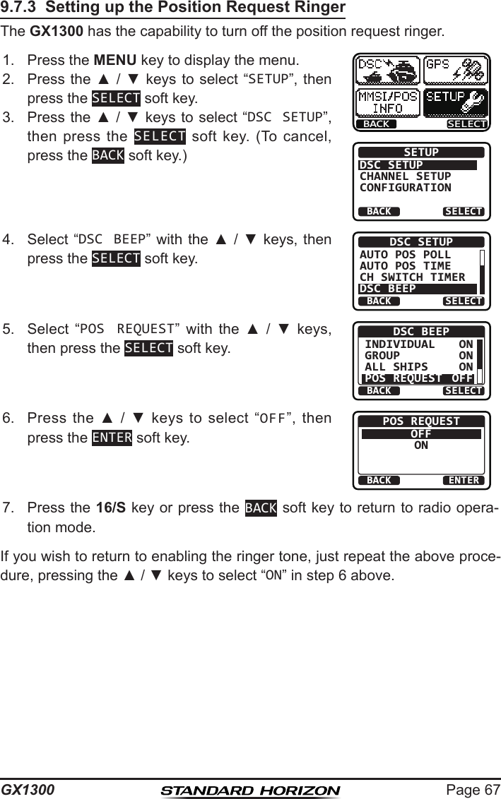
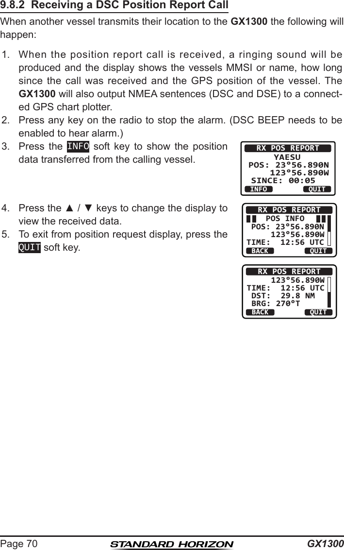
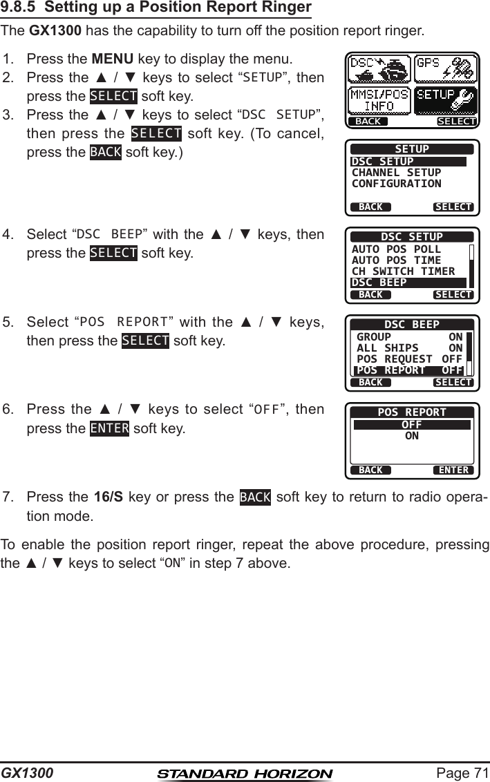
![GX1300Page 689.8 POSITION REPORTThe feature is similar to the position request, however instead of requesting a position of another vessel this function allows you to send your position to another vessel. In order to send your position you need to have a GPS receiver connected or to have manually input your position. See section “9.9 MANUAL INPUTTING OF THE GPS LOCATION.”9.8.1 Transmitting a DSC Position Report CallPosition Report from Individual / Position Call Directory1. Press the MENU key to display the menu.BACK SELECTBACK SELECTDSC CALLALL SHIPSDIST ALERT MSGPOS REQUESTPOS REPORT2. Press the ▲ / ▼ keys to select “DSC”, then press the SELECT soft key.3. Press the ▲ / ▼ keys to select “POS REPORT”, and then press the SELECT soft key. (To cancel, press the BACK soft key.)4. Press the ▲ / ▼ keys to select “HISTORY” or “MEMORY”, then press the SELECT soft key.BACK SELECTPOS REPORTHISTORYMEMORYNEW ID5. Press the ▲ / ▼ keys to select an individual you want to contact, then press the SELECT soft key.BACK SELECTMEMORYYAESUUSCGMEMORY SHIPSHORIZON6. Press the YES soft key to send your position to the selected vessel. Press the POS soft key to change the position information.POS REPORTYAESU POS: 23°56.890N 123°56.890W Transmit a Call?YESNOPOS/TM7. To exit from position request display, press the QUIT soft key.POS REPORT YAESU CATEG: SAFETY SINCE: 00:05[ Transmitted ]QUIT](https://usermanual.wiki/Yaesu-Musen/30583X3D/User-Guide-2532675-Page-68.png)
![Page 69GX1300Position Report - Manual MMSI EntryYou may enter an MMSI number manually to contact a vessel without storing the MMSI in the individual/position call directory.1. Press the MENU key to display the menu.BACK SELECTBACK SELECTDSC CALLALL SHIPSDIST ALERT MSGPOS REQUESTPOS REPORT2. Press the ▲ / ▼ keys to select “DSC”, then press the SELECT soft key.3. Press the ▲ / ▼ keys to select “POS REPORT”, and then press the SELECT soft key. (To cancel, press the BACK soft key.)4. Press the ▲ / ▼ keys to select “NEW ID”, then press the SELECT soft key.BACK SELECTPOS REPORTHISTORYMEMORYNEW ID5. Press the ▲ / ▼ keys to scroll through numbers, 0 to 9.BACK SELECTFINISHNEW IDMMSI: 3----------6. Press the SELECT soft key to store the number and step to the next digit to the right.7. Repeat steps 5 and 6 until the MMSI is complete. If a mistake was made entering in the MMSI number, press the ◄ / ► keys repeatedly until the wrong number is highlighted, then press the ▲ / ▼ keys to correct the entry.8. After the nineth number has been entered, press the FINISH soft key.9. Press the YES soft key to send your position to the selected vessel. Press the POS soft key to change the position information.POS REPORT366901555 POS: 23°56.890N 123°56.890W Transmit a Call?YESNOPOS/TM10. To exit from position request display, press the QUIT soft key.POS REPORT 366901555 CATEG: SAFETY SINCE: 00:05[ Transmitted ]QUIT](https://usermanual.wiki/Yaesu-Musen/30583X3D/User-Guide-2532675-Page-69.png)
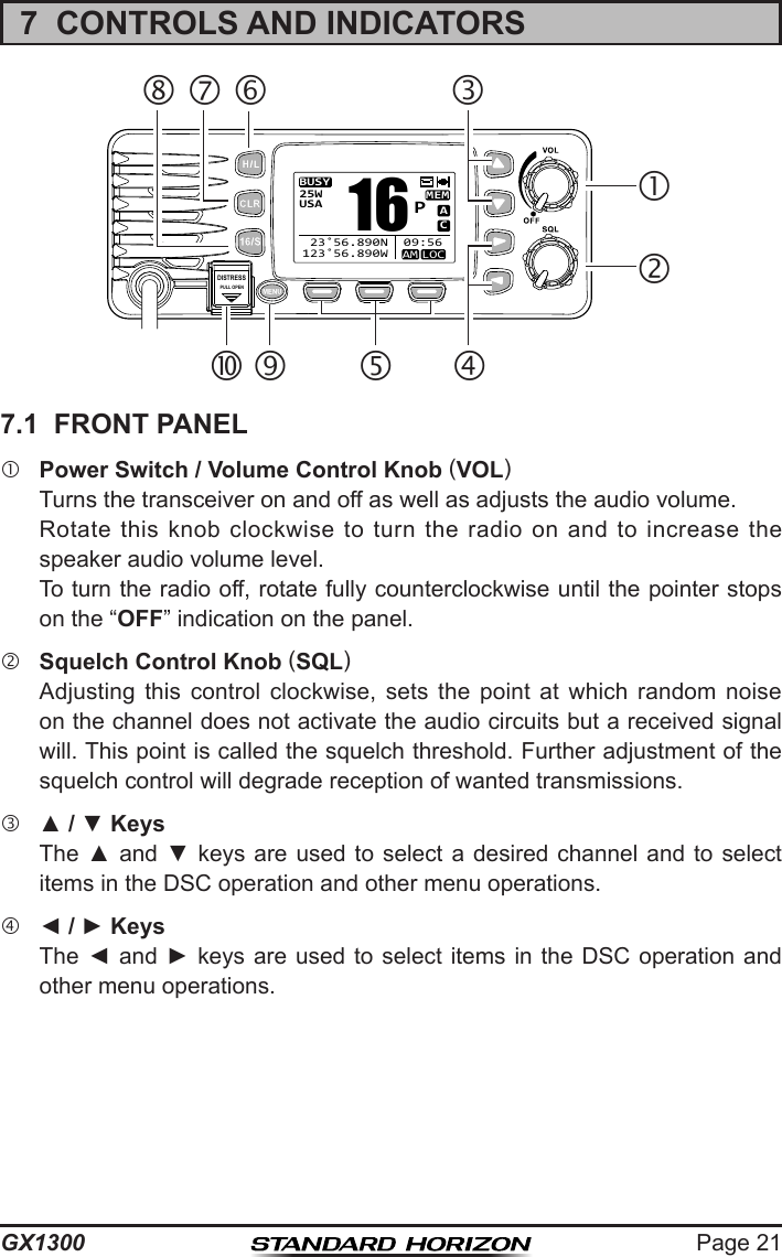
![GX1300Page 769.11 DSC TEST CALLUse the following procedure to ensure the DSC feature are functioning with other DSC radios.9.11.1 Transmitting a DSC Test CallDSC Test Call from Individual / Position Call Directory1. Press the MENU key to display the menu.BACK SELECTBACK SELECTDSC CALLPOS REQUESTPOS REPORTAUTO POS POLLINGTEST CALL2. Press the ▲ / ▼ keys to select “DSC”, then press the SELECT soft key.3. Press the ▲ / ▼ keys to select “TEST CALL”, and then press the SELECT soft key. (To cancel, press the BACK soft key.)4. Press the ▲ / ▼ keys to select “MEMORY”, then press the SELECT soft key.BACK SELECTTEST CALLMEMORYNEW ID5. Press the ▲ / ▼ keys to select an individual you want to contact, then press the SELECT soft key.BACK SELECTMEMORYYAESUUSCGMEMORY SHIPSHORIZON6. Press the YES soft key to transmit the test signal.TEST CALL YAESU CATEG: SAFETYTransmit a Call?YESNO7. After the DSC test call is transmitted, the GX1300 waits for a reply from the radio which was called, and the display will show “WAITING FOR ACK”. To transmit again, press the RESEND soft key.TEST CALL YAESU CATEG: SAFETY SINCE: 00:05[Waiting for ACK]RESEND QUIT8. When an acknowledgement signal is received, the GX1300 will show “RX TEST CALL” screen, which conrms the radio you called has received the test call.9. Press the QUIT soft key to return to the radio operation.](https://usermanual.wiki/Yaesu-Musen/30583X3D/User-Guide-2532675-Page-76.png)
![Page 77GX1300DSC Test Call - Manual MMSI Entry1. Press the MENU key to display the menu.BACK SELECTBACK SELECTDSC CALLPOS REQUESTPOS REPORTAUTO POS POLLINGTEST CALL2. Press the ▲ / ▼ keys to select “DSC”, then press the SELECT soft key.3. Press the ▲ / ▼ keys to select “TEST CALL”, and then press the SELECT soft key. (To cancel, press the BACK soft key.)4. Press the ▲ / ▼ keys to select “NEW ID”, then press the SELECT soft key.BACK SELECTTEST CALLMEMORYNEW ID5. Press the ▲ / ▼ keys to scroll through numbers, 0 to 9.BACK SELECTFINISHNEW IDMMSI: 3----------6. Press the SELECT soft key to store the number and step to the next digit to the right.7. Repeat steps 5 and 6 until the MMSI is complete. If a mistake was made entering in the MMSI number, press the ◄ / ► keys repeatedly until the wrong number is highlighted, then press the ▲ / ▼ keys to correct the entry.8. After the nineth number has been entered, press the FINISH soft key.9. Press the YES soft key to transmit the test signal.TEST CALL 366901555 CATEG: SAFETYTransmit a Call?YESNO10. After the DSC test call is transmitted, the GX1300 waits for a reply from the radio which was called, and the display will show “WAITING FOR ACK”. To transmit again, press the RESEND soft key.TEST CALL 366901555 CATEG: SAFETY SINCE: 00:05[Waiting for ACK]RESEND QUIT11. When an acknowledgement signal is received, the display will show “Received ACK”.TEST CALL 366901555 CATEG: SAFETY SINCE: 00:05[ Received ACK ]QUIT12. Press the QUIT soft key to return to the radio operation.](https://usermanual.wiki/Yaesu-Musen/30583X3D/User-Guide-2532675-Page-77.png)
![GX1300Page 789.11.2 Receiving a DSC Test CallWhen another vessel transmits a DSC test call to the GX1300, the radio automatically reply an acknowledgement. The display shows the MMSI or the name of the vessel transmitting the DSC test call. RX TEST CALL YAESU DSC TEST REPLY SINCE: 00:05[ Transmitted ]QUITPress the QUIT soft key to return to radio operation.](https://usermanual.wiki/Yaesu-Musen/30583X3D/User-Guide-2532675-Page-78.png)
![Page 79GX13009.12 POLLING CALLThe GX1300 has the capability to transmit a signal ensuring that another DSC radio is able to accept channel communication.9.12.1 Transmitting a Polling CallPosition Polling from Individual / Position Call Directory1. Press the MENU key to display the menu.BACK SELECTBACK SELECTDSC CALLAUTO POS POLLINGTEST CALLPOLLING CALLDSC LOG2. Press the ▲ / ▼ keys to select “DSC”, then press the SELECT soft key.3. Press the ▲ / ▼ keys to select “POLLING CALL”, and then press the SELECT soft key. (To cancel, press the BACK soft key.)4. Press the ▲ / ▼ keys to select “HISTORY” or “MEMORY”, then press the SELECT soft key.BACK SELECTPOLLING CALLHISTORYMEMORYNEW ID5. Press the ▲ / ▼ keys to select an individual you want to contact, then press the SELECT soft key.BACK SELECTMEMORYYAESUUSCGMEMORY SHIPSHORIZON6. Press the YES soft key to transmit the polling signal.POLLING CALL YAESU CATEG: ROUTINETransmit a Call?YESNO7. After the polling call is transmitted, the GX1300 waits for a reply from the radio which was called, and the display will show “WAITING FOR ACK”. To transmit again, press the RESEND soft key.POLLING CALL YAESU CATEG: ROUTINE SINCE: 00:05[Waiting for ACK]RESEND QUIT8. When an acknowledgement signal is received, the display will show “Received ACK”.POLLING CALL YAESU CATEG: ROUTINE SINCE: 00:05[ Received ACK ]QUIT9. Press the QUIT soft key to return to the radio operation.](https://usermanual.wiki/Yaesu-Musen/30583X3D/User-Guide-2532675-Page-79.png)
![GX1300Page 80Position Polling - Manual MMSI Entry1. Press the MENU key to display the menu.BACK SELECTBACK SELECTDSC CALLAUTO POS POLLINGTEST CALLPOLLING CALLDSC LOG2. Press the ▲ / ▼ keys to select “DSC”, then press the SELECT soft key.3. Press the ▲ / ▼ keys to select “POLLING CALL”, and then press the SELECT soft key. (To cancel, press the BACK soft key.)4. Press the ▲ / ▼ keys to select “NEW ID”, then press the SELECT soft key.BACK SELECTPOLLING CALLHISTORYMEMORYNEW ID5. Press the ▲ / ▼ keys to scroll through numbers, 0 to 9.BACK SELECTFINISHNEW IDMMSI: 3----------6. Press the SELECT soft key to store the number and step to the next digit to the right.7. Repeat steps 5 and 6 until the MMSI is complete. If a mistake was made entering in the MMSI number, press the ◄ / ► keys repeatedly until the wrong number is highlighted, then press the ▲ / ▼ keys to correct the entry.8. After the nineth number has been entered, press the FINISH soft key.9. Press the YES soft key to transmit the polling signal.POLLING CALL 366901555 CATEG: ROUTINETransmit a Call?YESNO10. After the polling call is transmitted, the GX1300 waits for a reply from the radio which was called, and the display will show “WAITING FOR ACK”. To transmit again, press the RESEND soft key.POLLING CALL 366901555 CATEG: ROUTINE SINCE: 00:05[Waiting for ACK]RESEND QUIT11. When an acknowledgement signal is received, the display will show “Received ACK”.POLLING CALL 366901555 CATEG: ROUTINE SINCE: 00:05[ Received ACK ]QUIT12. Press the QUIT soft key to return to the radio operation.](https://usermanual.wiki/Yaesu-Musen/30583X3D/User-Guide-2532675-Page-80.png)
![Page 81GX13009.12.2 Receiving a Polling CallWhen another vessel transmits a polling call to the GX1300, the radio automatically reply an acknowl-edgement. The display shows the MMSI or the name of the vessel transmitting the polling call. RX POLLING CALL YAESU POLLING REPLY SINCE: 00:05[ Transmitted ]QUITPress the QUIT soft key to return to radio operation.](https://usermanual.wiki/Yaesu-Musen/30583X3D/User-Guide-2532675-Page-81.png)
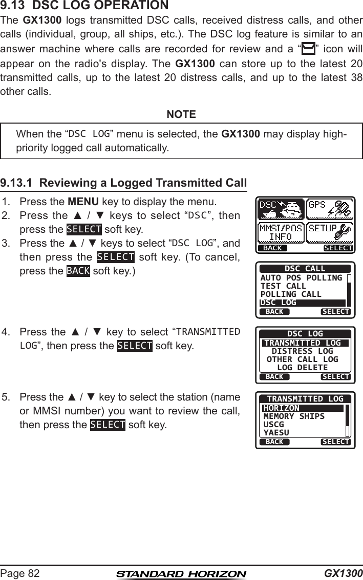
![Page 83GX13006. Press the ▲ / ▼ key to scroll the display.BACK DELETETRANSMITTED LOGINDIVIDUAL123456789YAESU TX TM: 12:56 UTCBACK DELETETRANSMITTED LOGDATE: 12/JANCATER: ROUTINECH: 06 [ Delayed ACK ]7. Press the BACK soft key to go back to the DSC transmitted call list.9.13.2 Reviewing a Logged DSC Distress Call1. Press the MENU key to display the menu.BACK SELECTBACK SELECTDSC CALLAUTO POS POLLINGTEST CALLPOLLING CALLDSC LOG2. Press the ▲ / ▼ keys to select “DSC”, then press the SELECT soft key.3. Press the ▲ / ▼ keys to select “DSC LOG”, and then press the SELECT soft key. (To cancel, press the BACK soft key.)4. Press the ▲ / ▼ key to select “DISTRESS LOG”, then press the SELECT soft key.BACK SELECTDSC LOGTRANSMITTED LOGDISTRESS LOGOTHER CALL LOGLOG DELETE5. Press the ▲ / ▼ key to select the station (name or MMSI number) you want to review. Note: When there is an unread received call, “” icon will appear at the head of the station name (or MMSI number).BACK SELECTDISTRESS LOGHORIZONMEMORY SHIPSUSCGYAESU Press the SELECT soft key to review details for the selected station.](https://usermanual.wiki/Yaesu-Musen/30583X3D/User-Guide-2532675-Page-83.png)
![GX1300Page 846. Press the ▲ / ▼ key to scroll the display.BACK DELETEDISTRESS LOG123456789YAESU RX TM: 12:56 UTCDATE: 12/JAN BACK DELETEDISTRESS LOGDATE: 12/JANCATER: ROUTINECH: 06 [ Delayed ACK ]7. Press the BACK soft key to go back to the DSC distress call list.9.13.3 Reviewing a Logged Other CallsThe GX1300 allows received calls (individual, group, all ships, etc.) to be reviewed.1. Press the MENU key to display the menu.BACK SELECTBACK SELECTDSC CALLAUTO POS POLLINGTEST CALLPOLLING CALLDSC LOG2. Press the ▲ / ▼ keys to select “DSC”, then press the SELECT soft key.3. Press the ▲ / ▼ keys to select “DSC LOG”, and then press the SELECT soft key. (To cancel, press the BACK soft key.)4. Press the ▲ / ▼ key to select “OTHER CALL LOG”, then press the SELECT soft key.BACK SELECTDSC LOGTRANSMITTED LOGDISTRESS LOGOTHER CALL LOGLOG DELETE5. Press the ▲ / ▼ key to select the station (name or MMSI number) you want to review. Note: When there is an unread received call, “” icon will appear at the head of the station name (or MMSI number).BACK SELECTOTHER CALL LOGHORIZONMEMORY SHIPSUSCGYAESU Press the SELECT soft key, to review details for the selected station.](https://usermanual.wiki/Yaesu-Musen/30583X3D/User-Guide-2532675-Page-84.png)
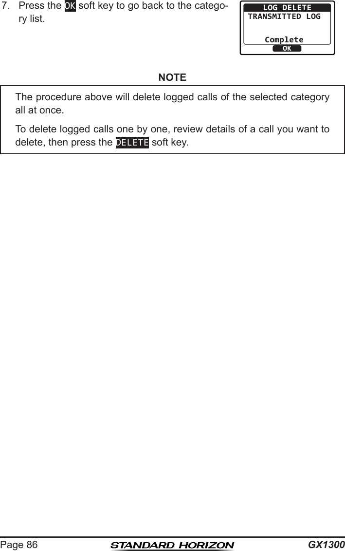
![Page 85GX13006. Press the ▲ / ▼ key to scroll the display.BACK DELETERX OTHER LOGINDIVIDUAL123456789YAESU RX TM: 12:56 UTCBACK DELETERX OTHER LOGDATE: 12/JANCATER: ROUTINECH: 06 [ Delayed ACK ]7. Press the BACK soft key to go back to the DSC other call list.9.13.4 Deleting Calls from the “DSC LOG” Directory1. Press the MENU key to display the menu.BACK SELECTBACK SELECTDSC CALLAUTO POS POLLINGTEST CALLPOLLING CALLDSC LOG2. Press the ▲ / ▼ keys to select “DSC”, then press the SELECT soft key.3. Press the ▲ / ▼ keys to select “DSC LOG”, and then press the SELECT soft key. (To cancel, press the BACK soft key.)4. Press the ▲ / ▼ key to select “LOG DELETE”, then press the SELECT soft key.BACK SELECTDSC LOGTRANSMITTED LOGDISTRESS LOGOTHER CALL LOGLOG DELETE5. Press the ▲ / ▼ key to select the category (“TRANSMITTED LOG”, “DISTRESS LOG”, “OTHER CALL LOG”, or “ALL LOG”) to be deleted, then press the SELECT soft key. BACK SELECTLOG DELETETRANSMITTED LOGDISTRESS LOGOTHER CALL LOGALL LOG6. Press the YES soft key to delete logs of the selected category. (To cancel, press the NO soft key.)YESNOLOG DELETETRANSMITTED LOGDo you want todelete it?](https://usermanual.wiki/Yaesu-Musen/30583X3D/User-Guide-2532675-Page-85.png)