Yaesu Musen 30583X3D CLASS D DSC MARINE TRANSCEIVER User Manual GX1300 User s Manual
Yaesu Musen Co., Ltd. CLASS D DSC MARINE TRANSCEIVER GX1300 User s Manual
User Manual

Page 1GX1300
ECLIPSE GX1300
25 Watt VHF/FM
Class D DSC Marine Transceiver
Owner's Manual
Affordable ultra compact class D xed mount VHF radio
Submersible IPX8 class (4.92 feet for 30 minutes) front
panel
Separate dedicated channel 70 receiver for DSC
Programmable soft keys
GPS position and time shown* on a full dot matrix display
DSC distress, individual, group, all ships, position request,
position report and DSC test call
Programmable scan, priority scan, and dual watch
NMEA in and output connections to a compatible GPS chart
plotter
All USA/International and Canadian marine channels
Meets ITU-R M493-13 class D DSC (Digital Selective
Calling)
* When GPS connected

GX1300Page 2
TABLE OF CONTENTS
Quick Reference Guide ..............................................................................................5
1 GENERAL INFORMATION ......................................................................................6
2 PACKING LIST ........................................................................................................7
3 OPTIONS .................................................................................................................7
4 ONLINE WARRANTY REGISTRATION (in USA or Canada only) ........................7
5 GETTING STARTED ................................................................................................8
5.1 ABOUT VHF RADIO ........................................................................................8
5.2 SELECTING AN ANTENNA .............................................................................8
5.2.1 Coaxial Cable ......................................................................................9
5.3 EMERGENCY (CHANNEL 16 USE) ..............................................................10
5.4 CALLING ANOTHER VESSEL (CHANNEL 16 OR 9) ...................................10
5.5 OPERATING ON CHANNELS 13 AND 67 (USA Channel Group Only) ........11
6 INSTALLATION ......................................................................................................12
6.1 LOCATION .....................................................................................................12
6.2 MOUNTING THE RADIO ...............................................................................12
6.2.1 Supplied Mounting Bracket ................................................................12
6.2.2 Optional MMB-84 Flush Mount Bracket .............................................13
6.3 ELECTRICAL CONNECTIONS .....................................................................14
6.4 ACCESSORY CABLE ....................................................................................16
6.5 CHECKING G0PS CONNECTIONS ..............................................................17
6.6 CHANGING THE GPS TIME .........................................................................18
6.7 CHANGING THE TIME LOCATION ...............................................................19
6.8 CHANGING THE TIME FORMAT ..................................................................20
7 CONTROLS AND INDICATORS ............................................................................21
7.1 FRONT PANEL ..............................................................................................21
7.2 REAR PANEL ................................................................................................23
7.3 MICROPHONE ..............................................................................................24
8 BASIC OPERATION ..............................................................................................25
8.1 RECEPTION ..................................................................................................25
8.2 TRANSMISSION ............................................................................................25
8.3 TRANSMIT TIME-OUT TIMER (TOT) ............................................................25
8.4 SIMPLEX/DUPLEX CHANNEL USE .............................................................26
8.5 INTERNATIONAL, USA, AND CANADA MODE ............................................26
8.6 NOAA WEATHER CHANNELS ......................................................................27
8.6.1 NOAA Weather Alert ..........................................................................27
8.6.2 NOAA Weather Alert Testing ..............................................................27
8.7 SCANNING ....................................................................................................28
8.7.1 Selecting the Scan Type ....................................................................28
8.7.2 Scan Memory Programming ..............................................................29
8.7.3 Memory Scanning (M-SCAN) ............................................................29
8.7.4 Priority Channel Setting .....................................................................30
8.7.5 Priority Scanning (P-SCAN) ...............................................................30
8.8 MULTI WATCH (TO PRIORITY CHANNEL) ..................................................31
8.8.1 Setting up the Multi Watch Operation ................................................31
8.8.2 Starting the Dual Watch .....................................................................32
8.9 PRESET CHANNELS: INSTANT ACCESS ...................................................33
8.9.1 Preset Channel Programming ...........................................................33
8.9.2 Operation ...........................................................................................33
8.9.3 Deleting a Preset Channel .................................................................34
8.10 OPERATION MENU ....................................................................................35
9 DIGITAL SELECTIVE CALLING ...........................................................................36
9.1 GENERAL ......................................................................................................36
9.2 MARITIME MOBILE SERVICE IDENTITY (MMSI) ........................................36
9.2.1 What is an MMSI? .............................................................................36

Page 3GX1300
TABLE OF CONTENTS
9.2.2 Programming the MMSI .....................................................................37
9.3 DSC DISTRESS ALERT ................................................................................38
9.3.1 Transmitting a DSC Distress Alert .....................................................38
9.3.2 Receiving a DSC Distress Alert .........................................................42
9.4 ALL SHIPS CALL ...........................................................................................43
9.4.1 Transmitting an All Ships Call ............................................................43
9.4.2 Receiving an All Ships Call ................................................................44
9.4.3 Setting up the All Ships Call Ringer ...................................................45
9.5 INDIVIDUAL CALL .........................................................................................46
9.5.1 Setting up the Individual / Position Call Directory ..............................46
9.5.2 Setting up Individual Call Reply .........................................................48
9.5.3 Setting up the Individual Call Acknowledge Message .......................49
9.5.4 Transmitting an Individual Call ...........................................................50
9.5.5 Receiving an Individual Call ...............................................................52
9.5.6 Setting up the Individual Call Ringer ..................................................54
9.6 GROUP CALL ................................................................................................56
9.6.1 Setting up a Group Call .....................................................................56
9.6.2 Transmitting a Group Call ..................................................................58
9.6.3 Receiving a Group Call ......................................................................61
9.6.4 Setting up the Group Call Ringer .......................................................62
9.7 POSITION REQUEST ...................................................................................63
9.7.1 Transmitting a Position Request to Another Vessel ...........................63
9.7.2 Receiving a Position Request ............................................................66
9.7.3 Setting up the Position Request Ringer .............................................67
9.8 POSITION REPORT ......................................................................................68
9.8.1 Transmitting a DSC Position Report Call ...........................................68
9.8.2 Receiving a DSC Position Report Call ...............................................70
9.8.5 Setting up a Position Report Ringer ..................................................71
9.9 MANUAL INPUTTING OF THE GPS LOCATION (LAT/LON) ........................72
9.10 AUTO POS POLLING ..................................................................................73
9.10.1 Setting up the Polling Call Type .......................................................73
9.10.2 Setting up the Polling Time Interval .................................................73
9.10.3 Selecting Stations to be Automatically Polled ..................................74
9.10.4 Enabling/Disabling Auto POS Polling ..............................................75
9.11 DSC TEST CALL ..........................................................................................76
9.11.1 Transmitting a DSC Test Call ...........................................................76
9.11.2 Receiving a DSC Test Call ...............................................................78
9.12 POLLING CALL ...........................................................................................79
9.12.1 Transmitting a Polling Call ...............................................................79
9.12.2 Receiving a Polling Call ...................................................................81
9.13 DSC LOG OPERATION ...............................................................................82
9.13.1 Reviewing a Logged Transmitted Call .............................................82
9.13.2 Reviewing a Logged DSC Distress Call ..........................................83
9.13.3 Reviewing a Logged Other Calls .....................................................84
9.13.4 Deleting Calls from the “DSC LOG” Directory .................................85
10 SETUP MENU ......................................................................................................87
10.1 CONFIGURATION SETUP ..........................................................................87
10.1.1 Lamp Adjusting ................................................................................87
10.1.2 LCD Contrast ...................................................................................87
10.1.3 Key Beep .........................................................................................88
10.1.4 Location Format ...............................................................................89
10.1.5 Time Offset ......................................................................................89
10.1.6 Time Display ....................................................................................89
10.1.7 Time Format .....................................................................................89
10.1.8 Soft Keys .........................................................................................90

GX1300Page 4
TABLE OF CONTENTS
10.2 CHANNEL SETUP .......................................................................................92
10.2.1 Channel Group (Band Selection) .....................................................92
10.2.2 Weather Alert ...................................................................................92
10.2.3 Multi Watch ......................................................................................92
10.2.4 Scan Memory ...................................................................................92
10.2.5 Scan Type ........................................................................................93
10.2.6 Scan Resume ..................................................................................93
10.2.7 Priority Channel ...............................................................................93
10.2.8 Sub Channel ....................................................................................93
10.3 DSC SETUP ................................................................................................95
10.3.1 Individual Directory ..........................................................................95
10.3.2 Individual Reply ...............................................................................95
10.3.3 Individual Acknowledgement ...........................................................95
10.3.4 Individual Ringer ..............................................................................95
10.3.5 Group Directory ...............................................................................96
10.3.6 Auto Position Polling Call Type ........................................................96
10.3.7 Auto Position Polling Interval Time ..................................................96
10.3.8 Auto Channel Switching Time ..........................................................97
10.3.9 DSC Beep ........................................................................................97
11 MAINTENANCE ...................................................................................................98
11.1 REPLACEMENT PARTS ..............................................................................98
11.2 FACTORY SERVICE ....................................................................................98
11.3 TROUBLESHOOTING CHART ....................................................................99
12 CHANNEL ASSIGNMENTS ...............................................................................100
13 WARRANTY .......................................................................................................106
14 SPECIFICATIONS .............................................................................................. 110
14.1 GENERAL ..................................................................................................110
14.2 TRANSMITTER .........................................................................................110
14.3 RECEIVER ................................................................................................ 111
14.4 GX1300 DIMENSIONS ..............................................................................112
15 FCC RADIO LICENSE INFORMATION ............................................................. 113
15.1 STATION LICENSE ...................................................................................113
15.2 RADIO CALL SIGN ....................................................................................113
15.3 CANADIAN SHIP STATION LICENSING ..................................................113
15.4 FCC / INDUSTRY CANADA INFORMATION ............................................113
16 FCC NOTICE ......................................................................................................114
Page 5GX1300
Quick RefeRence Guide
Rotate the VOL knob clockwise until it clicks to turn on the radio.
Rotate the VOL knob to adjust the speaker audio volume.
Press the ▲ or ▼ key on the radio to select the operating channel.
Move the SQL knob clockwise to squelch or counter clockwise to
un-squelch the radio.
Press the 16/S key on the radio to select Channel 16. Press and hold the
16/S key on the radio to select the sub channel. Press again to revert to
the last selected channel.
Press the H/L key to toggle the transmit power between High (25W) and
Low (1W).
To transmit: place your mouth about 1" away from the MIC hole of the
microphone and speak in a normal voice level while pressing the PTT
switch.
Press the MENU key to access the menu list.
MIC HoLe
DISTRESS
PULL OPEN
BUSY
MEM
LOCAM
A
C
USA
25W
123˚56.890W
23˚56.890N 09:56
P
16

GX1300Page 6
1 GENERAL INFORMATION
The GX1300 ECLIPSE is a marine VHF transceiver designed for use in the
frequency range of 156.025 to 163.275 MHz. The GX1300 can be operated
from 11 to 16 VDC and has a switchable RF output power of 1 watt or 25
watts.
The GX1300 is capable of DSC (Digital Selective Calling) Class D (indepen-
dent Channel 70 receiver) operation which allows continuous receiving of
Digital Selective Calling functions on channel 70 even if the radio is receiving
a call.
The GX1300 operates on all currently-allocated marine channels which are
switchable for use with either International, USA, or Canadian regulations. It
has an emergency channel 16 which can be immediately selected from any
channel by pressing the red 16/S key.
Other features of the transceiver include: scanning, priority scanning, high
and low voltage warning, and GPS repeatability.

Page 7GX1300
2 PACKING LIST
When the package containing the transceiver is rst opened, please check it
for the following contents:
GX1300 Transceiver
Mounting Bracket, two Mounting Knobs, and hardware
Power Cord with 6 Amp fuse and holder
Owner’s Manual
3 OPTIONS
MMB-84 ..........................................................................Flush-Mount Bracket
MLS-310 ...............................................................Amplied External Speaker
MLS-300 .......................................................................External Loudspeaker
HC1100 ..........................................................................................Dust Cover
4 ONLINE WARRANTY REGISTRATION
(in USA or Canada only)
Please visit www.standardhorizon.com to register the GX1300 Marine VHF. It
should be noted that visiting the website from time to time may be benecial
to you, as new products are released they will appear on the STANDARD
HORIZON website.
PRODUCT SUPPORT INQUIRIES
If you have any questions or comments regarding the use of the GX1300,
you can visit the STANDARD HORIZON website to send an E-Mail or contact
the Product Support team at (800) 767-2450 M-F 8:00-5:00 PST.

GX1300Page 8
5 GETTING STARTED
5.1 ABOUT VHF RADIO
The radio frequencies used in the VHF marine band lie between 156 and
158 MHz with some shore stations available between 161 and 163 MHz. The
marine VHF band provides communications over distances that are essen-
tially “line of sight” (VHF signals do not travel well through objects such as
buildings, hills or trees). Actual transmission range depends much more on
antenna type, gain and height than on the power output of the transmitter. On
a xed mount 25 W radio transmission expected distances can be greater
than 15.5 miles (25 km), for a portable 5 W radio transmission the expected
distance can be greater than 5 miles (8 km) in “line of sight”.
5.2 SELECTING AN ANTENNA
Marine antennas are made to radiate signals equally in all horizontal direc-
tions, but not straight up. The objective of a marine antenna is to enhance
the signal toward the horizon. The degree to which this is accomplished is
called the antenna’s gain. It is measured in decibels (dB) and is one of the
major factors in choosing an antenna. In terms of effective radiated power
(ERP), antennas are rated on the basis of how much gain they have over
a theoretical antenna with zero gain. A 3.28 feet (1 m), 3 dB gain antenna
represents twice as much gain over the imaginary antenna.
Typically a 3.28 feet (1 m) 3 dB gain stainless steel whip is used on a
sailboat mast. The longer 8.2 feet (2.5 m) 6 dB berglass whip is primarily
used on power boats that require the additional gain.
3dB
6dB
9dB
Page 9GX1300
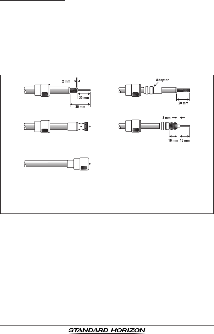
5.2.1 Coaxial Cable
VHF antennas are connected to the transceiver by means of a coaxial cable
– a shielded transmission line. Coaxial cable is specied by it’s diameter and
construction.
For runs less than 20 feet (6 m), RG-58/U (about 0.25" (6 mm) in diameter),
is a good choice. For runs over 20 feet (6 m) but less than 50 feet (15 m), the
larger RG-8X or RG-213/U should be used. For cable runs over 50 feet (15 m)
RG-8X should be used. For installation of the connector onto the coaxial
cable refer to the gure below.
To get your coax cable through a tting and into your boat’s interior,
you may have to cut off the end plug and reattach it later. You can do
this if you follow the directions that are supplied with the connector.
Be sure to make good soldered connections.

GX1300Page 10
5.3 EMERGENCY (CHANNEL 16 USE)
Channel 16 is known as the Hail and Distress Channel. An emergency is
dened as a threat to life or property. In such instances, be sure the trans-
ceiver is on and set to CHANNEL 16. Then use the following procedure:
1. Press the microphone push-to-talk switch and say “Mayday, Mayday,
Mayday. This is , , ” (your vessel’s name).
2. Then repeat once: “Mayday, ” (your vessel’s name).
3. Now report your position in latitude/longitude, or by giving a true or
magnetic bearing (state which) to a well-known landmark such as a
navigation aid or geographic feature such as an island or harbour entry.
4. Explain the nature of your distress (sinking, collision, aground, re, heart
attack, life-threatening injury, etc.).
5. State the kind of assistance you desire (pumps, medical aid, etc.).
6. Report the number of persons aboard and condition of any injured.
7. Estimate the present seaworthiness and condition of your vessel.
8. Give your vessel’s description: length, design (power or sail), color and
other distinguishing marks. The total transmission should not exceed 1
minute.
9. End the message by saying “OVER.” Release the microphone button
and listen.
10. If there is no answer, repeat the above procedure. If there is still no
response, try another channel.
NOTE
5.4 CALLING ANOTHER VESSEL (CHANNEL 16 OR 9)
Channel 16 may be used for initial contact (hailing) with another vessel.
However, its most important use is for emergency messages. This channel
must be monitored at all times except when actually using another channel.
It is monitored by the European, U.S. and Canadian Coast Guards and by
other vessels. Use of channel 16 for hailing must be limited to initial
contact only. Calling should not exceed 30 seconds, but may be repeated
3 times at 2-minute intervals. In areas of heavy radio traffic, congestion
on channel 16 resulting from its use as a hailing channel can be reduced
signicantly in U.S. waters by using channel 9 as the initial contact (hailing)
channel for non-emergency communications. Here, also, calling time should
The GX1300 have DSC Distress calling, that can transmit a distress
call digitally to all ships with compatible DSC radios. Refer to section “9
DIGITAL SELECTIVE CALLING”.

Page 11GX1300
not exceed 30 seconds but may be repeated 3 times at 2-minute intervals.
Prior to making contact with another vessel, refer to the channel charts in this
manual, and select an appropriate channel for communications after initial
contact. For example, Channels 68 and 69 are some of the channels avail-
able to non-commercial (recreational) boaters. Monitor your desired channel
in advance to make sure you will not be interrupting other trafc, and then go
back to either channel 16 or 9 for your initial contact.
When the hailing channel (16 or 9) is clear, state the name of the other
vessel you wish to call and then “this is” followed by the name of your vessel
and your Station License (Call Sign). When the other vessel returns your
call, immediately request another channel by saying “go to,” the number of
the other channel, and “over.” Then switch to the new channel. When the
new channel is not busy, call the other vessel.
After a transmission, say “over,” and release the microphone’s push-to-talk
(PTT) switch. When all communication with the other vessel is completed,
end the last transmission by stating your Call Sign and the word “out.” Note
that it is not necessary to state your Call Sign with each transmission, only at
the beginning and end of the contact.
Remember to return to Channel 16 when not using another channel. Some
radios automatically monitor Channel 16 even when set to other channels or
when scanning.
5.5 OPERATING ON CHANNELS 13 AND 67
(USA Channel Group Only)
Channel 13 is used at docks, bridges and by vessels manoeuvring in port.
Messages on this channel must concern navigation only, such as meeting
and passing in restricted waters.
Channel 67 is used for navigational trafc between vessels.
By regulation, power is normally limited to 1 Watt on these channels. Your
radio is programmed to automatically reduce power to this limit on these
channels. However, in certain situations it may be necessary to temporarily
use a higher power. See page 23 (H/L key) for means to temporarily override
the low-power limit on these two channels.
GX1300Page 12
6 INSTALLATION
6.1 LOCATION
The radio can be mounted at any angle. Choose a mounting location that:
• keeps the radio and microphone at least 3 feet (1 m) away from your
vessel’s magnetic navigation compass
• provides accessibility to the front panel controls
• allows connection to a power source and an antenna
• has nearby space for installation of a microphone hanger
• the antenna must be mounted at least 3 feet (1 m) from radio
Note: To insure the radio does not affect the compass, or that the radios
performance is not affected by the antenna location, temporarily connect the
radio in the desired location and:
a. Examine the compass to see if the radio causes any deviation
b. Connect the antenna and key the radio. Check to ensure the radio is
operating correctly by requesting a radio check.
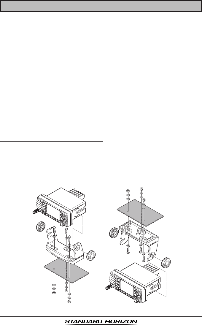
6.2 MOUNTING THE RADIO
6.2.1 Supplied Mounting Bracket
The supplied mounting bracket allows overhead or desktop mounting.
Use a 0.2" (5.2 mm) bit to drill the holes to a surface which is more 0.4" (10
mm) thick and can support more than 3.3 lb (1.5 kg). Secure the bracket with
the supplied screws, spring washers, at washers, and nuts.
Desktop Mounting Overhead Mounting
Page 13GX1300
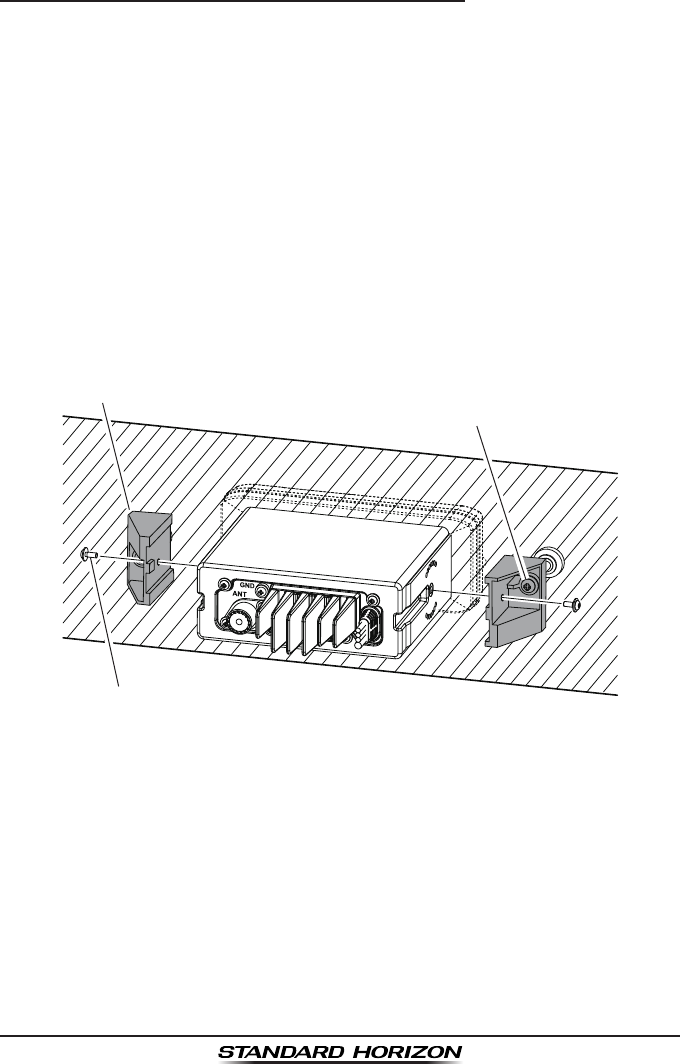
6.2.2 Optional MMB-84 Flush Mount Bracket
1. To assist in flush mounting, a template has been included. Use this
template to assess the mounting location.
2. Use the template to mark the location where the rectangular hole is to
be cut. Conrm the space behind the dash or panel is deep enough to
accommodate the transceiver (at least 5.5" (14 cm) deep).
There should be at least 0.5" (1.3 cm) between the transceiver’s heatsink
and any wiring, cables or structures.
3. Cut out the rectangular hole and insert the transceiver.
4. Fasten the brackets to the sides of the transceiver with the lock washer
nut combination, so that the mounting screw base faces the mounting
surface.
5. Turn the adjusting screw to adjust the tension so that the transceiver is
tight against the mounting surface.
MMB-84 Flush Mount Installation
Bracket
Adjusting Screw
Lock-washer nut combination
GX1300Page 14
6.3 ELECTRICAL CONNECTIONS
CAUTION
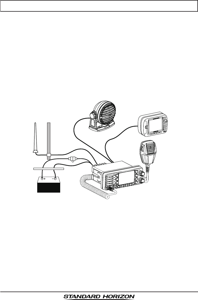
Connect the power cord and antenna to the radio. Antenna and Power
Supply connections are as follows (see Figure 1):
1. Mount the antenna at least 3.28 feet (1 m) away from the radio. At the
rear of the radio, connect the antenna cable.
2. Connect the red power wire to a 13.8 VDC ±20 % power source. Connect
the black power wire to a negative ground.
3. If an optional remote extension speaker is to be used, refer to next
section for connections.
4. It is advisable to have a Certified Marine Technician check the power
output and the standing wave ratio of the antenna after installation.
Figure 1. General Installation
Reverse polarity connections will damage the radio!
GPS
Char
t 150
GPS Navigation Receiver
Accessory Cable
Optional Speaker
Antenna
Fuse
Red
Power Source
Black
Water proof
Deck Outlet
Page 15GX1300
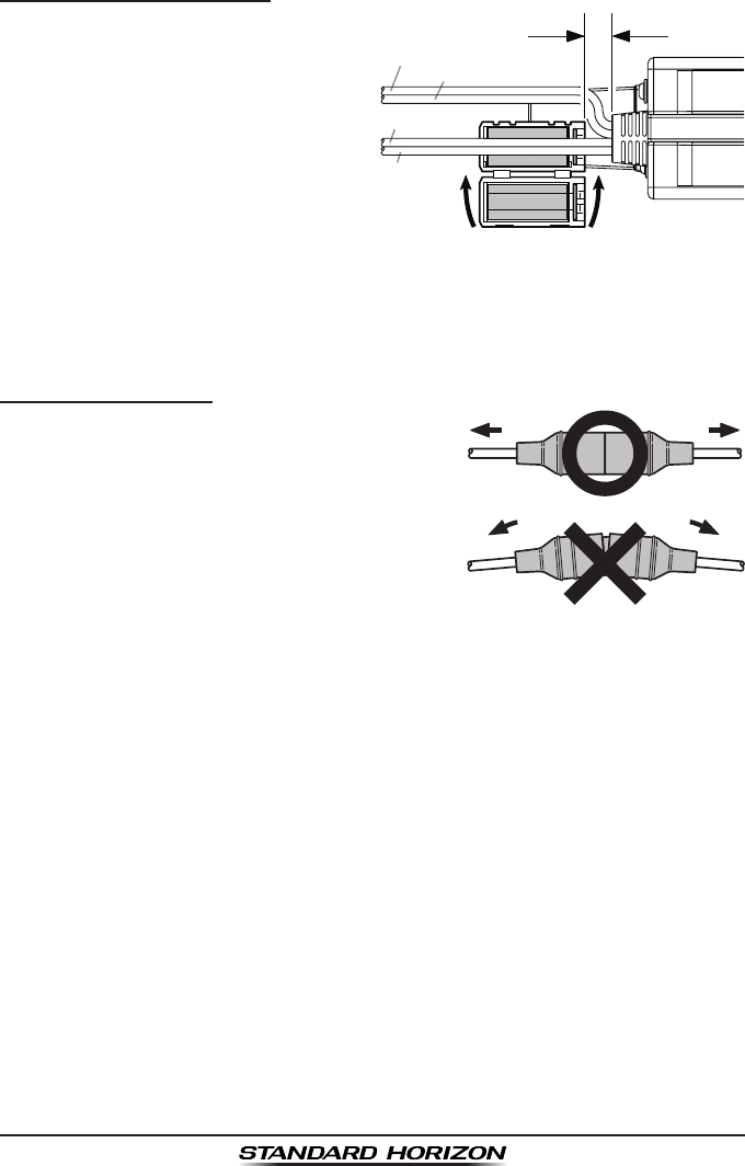
Ferrite Core Installation
To suppress RF interference
that can cause abnormalopera-
tion of the transceiver, attach the
supplied ferritecore to the both
External Speaker Connection
Cable and GPS Connection Cable
together, then snap its two halves-
together, per the illustration below.
Attach the ferrite core as close as
possible to thetransceiver body, as shown. Finally, wind some plastic tape
around the ferrite core, toprevent vibration from causing the two halves to
split apart.
Fuse Replacement
To take out the Fuse from the Fuse Holder,
hold both ends of the Fuse Holder and pull
the Fuse Holder apart, do not bend the Fuse
Holder. When you replace the Fuse, please
confirm that the Fuse is tightly fixed on the
metal contact located inside the Fuse Holder.
If the metal contact holding the fuse is loose,
the Fuse holder may heat up.
As close as possible
Snap together
Ferrite Core
DC Power Cable (RED)
DC Power Cable (Black)
GPS Connection
Cable
External Speaker
Connection Cable
GX1300Page 16
6.4 ACCESSORY CABLE
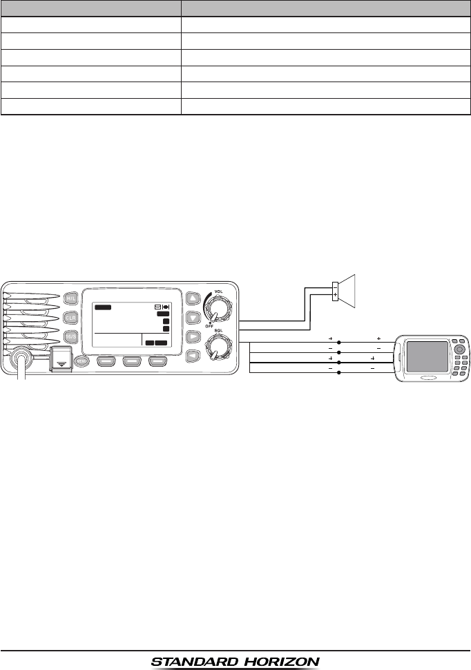
When connecting the external speaker or GPS navigation receiver, strip
off about 1" (2.5 cm) of the specied wire’s insulation, then splice the ends
together using proper waterproong techniques.
Wire Color/Description Connection Examples
WHITE - External Speaker (+)Connect to external 4-ohm audio speaker
SHIELD - External Speaker (–) Connect to external 4-ohm audio speaker
YELLOW - NMEA GPS Input (+)Connect to NMEA (+) output of GPS
GREEN - NMEA GPS Input (–)
Connect to NMEA (–) output or common ground of GPS
WHITE - NMEA DSC Output (+)Connect to NMEA (+) input of GPS
BROWN - NMEA DSC Output (–)
Connect to NMEA (–) input of GPS
: Some GPS chart plotters have a single wire for NMEA signal ground.
In such a case connect the NMEA input (–) to the GPS chart plotter's
single NMEA signal ground wire, and leave the NMEA output (–) open.
In case the assignment of power supply and ground of a GPS chart
plotter to be used is different from that of the radio, connect the signal
ground wire of the GPS chart plotter to the ground terminal (GND) on the
rear panel of the radio.
• The GPS must have the NMEA Output turned on and set to 4800 Baud
in the SETUP menu. If there is a selection for parity select none.
• For further information on interfacing /setting up your GPS. Please
contact the manufacturer of the GPS receiver.
• GX1300 can read NMEA-0183 version 2.0 or higher.
• The NMEA supported sentences are:
Input: GLL, GGA, RMC, GNS, GSA and GSV (RMC sentence is
recommended)
Output: DSC and DSE
GPS Receiver/Plotter
External Speaker
Shield
White
Green: NMEA GPS Input ( )
White: NMEA DSC Output ( )
NMEA OUT ( )
NMEA IN ( )
NMEA OUT ( )
NMEA IN ( )
Yellow: NMEA GPS Input ( )
Brown: NMEA DSC Output ( )
DISTRESS
PULL OPEN
BUSY
MEM
LOCAM
A
C
USA
25W
123˚56.890W
23˚56.890N 09:56
P
16
Page 17GX1300
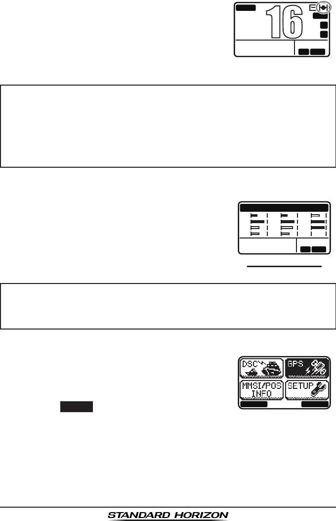
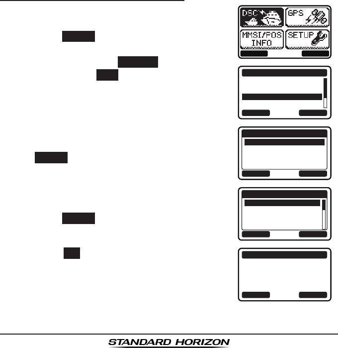
6.5 CHECKING GPS CONNECTIONS
After connections have been made between the
GX1300 and the GPS, a small satellite icon will
appear on the top right corner of the display, and
displays your current location (Latitude/Longitude)
on the display.
BUSY
MEM
LOCAM
A
C
USA
25W
123˚56.890W
23˚56.890N 09:56
P
16
NOTE
The GX1300 has a GPS status display which
shows the satellites currently being received, along
with a graphical (bar-graph) representation of the
relative signal strengths from the satellites.
(GPS StatuS DISPLay)
GPS STATUS
LOCAM
123˚56.890W
23˚56.890N 09:56
01
12
13
15
21
22
25
28
31
32
AS
--
NOTE
1. Turn the transceiver on.
BACK SELECT
2. Press the MENU key to display the menu.
3. Select “GPS” with the ▲ / ▼ / ◄ / ► key, then
press the SELECT soft key.
The “GPS STATUS” screen will appear.
4. Press the CLR key to return to radio operation.
• If there is a problem with the NMEA input from a GPS, the satellite
icon will blink continuously until the connection is corrected.
• If a GPS with NMEA output is not connected to the radio, the
GX1300 will beep 10 minutes after the radio is turned on. After that
the GX1300 will beep every 4 hours alerting to connect a GPS.
For the GX1300 to properly show the GPS status page when an ex-
ternal GPS antenna or a chart plotter is connected it must be setup to
output GSA and GSV NMEA 0183 sentences.
GX1300Page 18
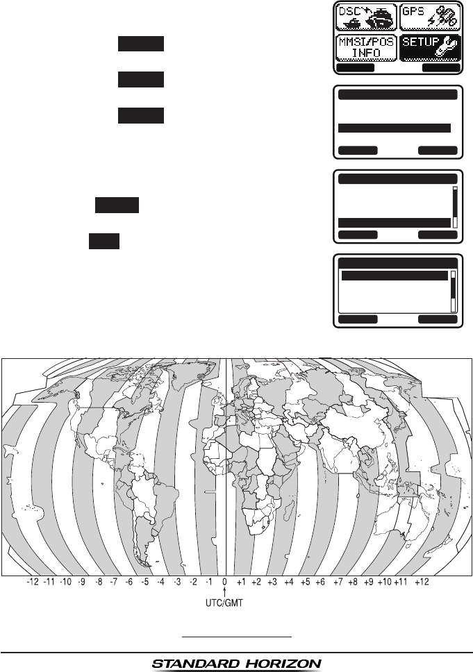
6.6 CHANGING THE GPS TIME
From the factory the GX1300 displays GPS satellite time or UTC (Universal
Time Coordinated or GMT (Greenwich Mean Time)) time. A time offset is
needed to show the local time in your area.
1. Press the MENU key to display the menu.
BACK SELECT
BACK SELECT
SETUP
DSC SETUP
CHANNEL SETUP
CONFIGURATION
BACK SELECT
CONFIGURATION
CONTRAST
KEY BEEP
LOCATION FORMT
TIME OFFSET
BACK ENTER
TIME OFFSET
00:00
+00:30
+01:00
+01:30
2. Select “SETUP” with the ▲ / ▼ / ◄ / ► keys,
then press the SELECT soft key.
3. Select “CONFIGURATION” with the ▲ / ▼ keys,
then press the SELECT soft key.
4. Select “TIME OFFSET” with the ▲ / ▼ keys,
then press the SELECT soft key.
5. Press the ▲ / ▼ keys to select time offset from
UTC. See illustration below to nd your offset
time from UTC. If “00:00” is assigned, the time
is the same as UTC.
6. Press the ENTER soft key to store the time
offset.
7. Press the BACK soft key to exit the menu.
offSet tIMe tabLe
Page 19GX1300
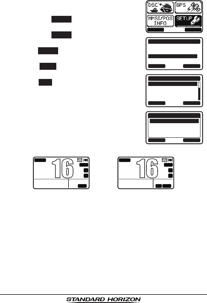
6.7 CHANGING THE TIME LOCATION
This menu item allows you to choose to show UTC or the local time which is
selected in Section 6.6.
1. Press the MENU key to display the menu.
BACK SELECT
BACK SELECT
SETUP
DSC SETUP
CHANNEL SETUP
CONFIGURATION
BACK SELECT
CONFIGURATION
TIME AREA
TIME FORMAT
SOFT KEY
RESET
BACK ENTER
TIME AREA
UTC
LOCAL
2. Select “SETUP” with the ▲ / ▼ / ◄ / ► keys,
then press the SELECT soft key.
3. Select “CONFIGURATION” with the ▲ / ▼ keys,
then press the SELECT soft key.
4. Select “TIME AREA” with the ▲ / ▼ keys, then
press the SELECT soft key.
5. Press the ▲ / ▼ to select “UTC” or “LOCAL”.
6. Press the ENTER soft key to store the selected
setting.
7. Press the BACK soft key to exit the menu.
(“UTC” mode)
BUSY
MEM
UTC
A
C
USA
25W
123˚56.890W
23˚56.890N 09:56
P
16
(“LOCAL” mode)
BUSY
MEM
LOCAM
A
C
USA
25W
123˚56.890W
23˚56.890N 09:56
P
16
GX1300Page 20
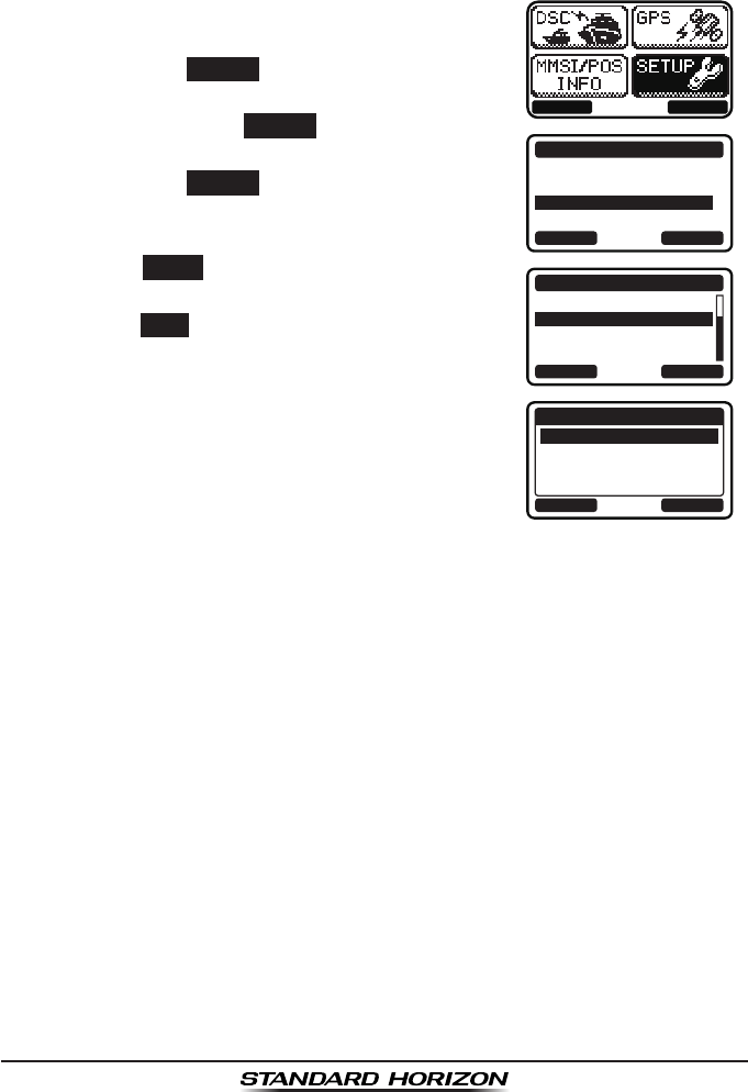
6.8 CHANGING THE TIME FORMAT
This menu item allows you to choose to show time in 12-hour or 24-hour
format.
1. Press the MENU key to display the menu.
BACK SELECT
BACK SELECT
SETUP
DSC SETUP
CHANNEL SETUP
CONFIGURATION
BACK SELECT
CONFIGURATION
TIME AREA
TIME FORMAT
SOFT KEY
RESET
BACK ENTER
TIME FORMAT
24 HOURS
12 HOURS
2. Select “SETUP” with the ▲ / ▼ / ◄ / ► keys,
then press the SELECT soft key.
3. Select “CONFIGURATION” with the ▲ / ▼
keys, then press the SELECT soft key.
4. Select “TIME FORMAT” with the ▲ / ▼ keys,
then press the SELECT soft key.
5. Press the ▲ / ▼ to select “12 HOURS” or “24
HOURS”.
6. Press the ENTER soft key to store the select-
ed setting.
7. Press the BACK soft key to exit the menu.
Page 21GX1300
7 CONTROLS AND INDICATORS
DISTRESS
PULL OPEN
BUSY
MEM
LOCAM
A
C
USA
25W
123˚56.890W
23˚56.890N 09:56
P
16
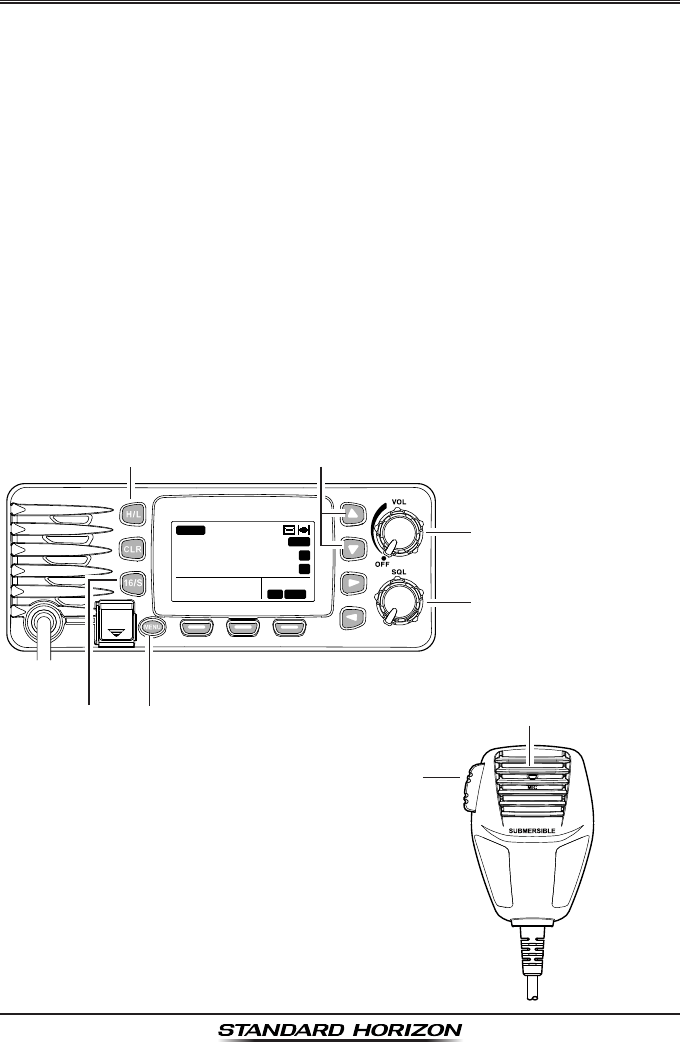
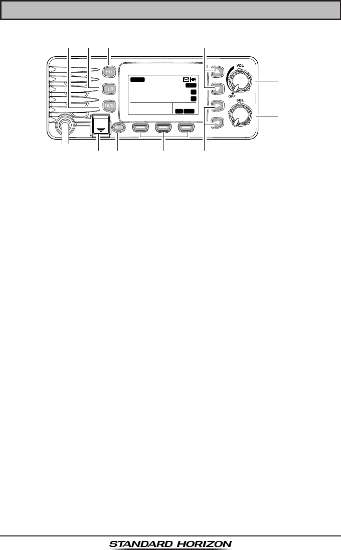
7.1 FRONT PANEL
Power Switch / Volume Control Knob (VOL)
Turns the transceiver on and off as well as adjusts the audio volume.
Rotate this knob clockwise to turn the radio on and to increase the
speaker audio volume level.
To turn the radio off, rotate fully counterclockwise until the pointer stops
on the “OFF” indication on the panel.
Squelch Control Knob (SQL)
Adjusting this control clockwise, sets the point at which random noise
on the channel does not activate the audio circuits but a received signal
will. This point is called the squelch threshold. Further adjustment of the
squelch control will degrade reception of wanted transmissions.
▲ / ▼ Keys
The ▲ and ▼ keys are used to select a desired channel and to select
items in the DSC operation and other menu operations.
◄ / ► Keys
The ◄ and ► keys are used to select items in the DSC operation and
other menu operations.

GX1300Page 22
Soft Keys
The 3 programmable soft keys can be customized by the SETUP menu
(see the section “10.1.7 SOFT KEYS”). When one of the soft keys is
pressed briey, the functions will appear above each key on the display.
The factory defaults are Key 1: CH, Key 2: DW/TW, Key 3: SCAN and Key 4:
SCAN MEM function.
Appropriate functions are automatically assigned to these keys during
the menu and the DSC operations.
H/L Key
Press this key to toggle the transmit output power between 25 W (High)
and 1 W (Low) power. When the H/L key is pressed while the transceiver
is on channel 13 or 67, the power will temporarily switch from LO to HI
power until the PTT is released.
The H/L key does not function on transmit inhibited and low power only
channels.
CLR Key
Immediately recalls the previous selected working channel during the
DSC operation and other menu operations.
16/S Key
Immediately recalls channel 16 from any channel location and automati-
cally selects high power. Pressing and holding this key recalls sub
channel. Pressing the 16/S key again reverts to the previous selected
working channel.
MENU Key
Press this key to access the menu list. The “DSC”, “GPS”, “MMSI/POS
INFO”, and “SETUP” functions can be accessed from the menu.
NOTE
DISTRESS Key
Used to send a DSC Distress Call. To send the distress call refer to
section “9.3.1 Transmitting a DSC Distress Alert”.
Before the “DSC” menu can be selected an MMSI must be entered.
Refer to section “9.2 MARITIME MOBILE SERVICE IDENTITY
(MMSI).”
Page 23GX1300
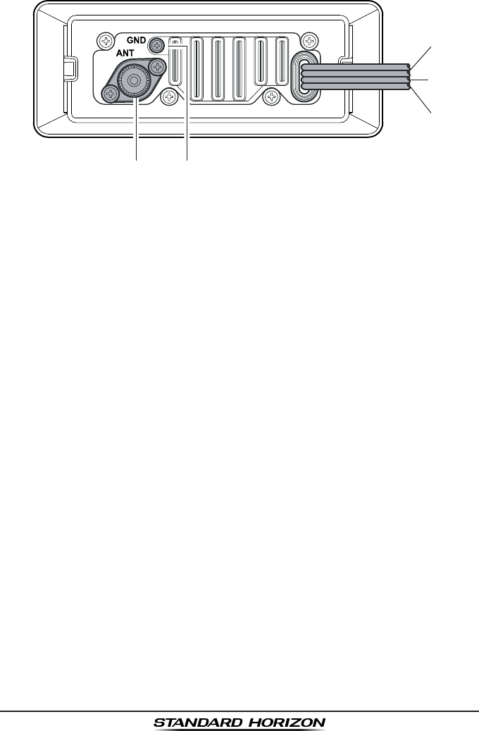
7.2 REAR PANEL
DC Input Cable
Connects the radio to a DC power supply capable of delivering 12V DC.
External Speaker Connection Cable
Connects the GX1300 to an external speaker.
GPS Receiver Connection Cable
Connects the GX1300 to a GPS receiver.
Ground Terminal (GND)
Connects the GX1300 to a good ground, for safety and optimum perfor-
mance.
Normally, the GND connection to the heat sink is not needed. However,
when the DC power cable connection to the radio has a long run, the
transmitter may become unstable and the receiving audio may be noisy.
In such a case, connect a large diameter, short cable between this termi-
nal on the heat sink and battery ground.
Install only the supplied screw or similar size (M3x6, Stainless
Steel) screw.
Antenna Jack (ANT)
Connects an antenna to the transceiver. Use a marine VHF antenna with
an impedance of 50 ohms.
GX1300Page 24
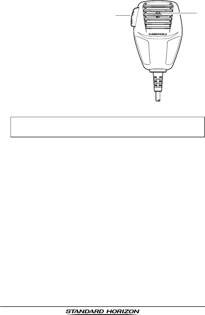
7.3 MICROPHONE
PTT (Push-To-Talk) Switch
Keys the transmitter when the
transceiver is in radio mode.
MIC (Microphone) Hole
Transmits the voice message with
reduction of background noise,
using Clear Voice Noise Reduction
Technology.
NOTE
Be sure your mouth is about 1" (1.3 cm) from the MIC hole for
best performance.

Page 25GX1300
8 BASIC OPERATION
8.1 RECEPTION
1. After the GX1300 has been installed, ensure that the power supply and
antenna are properly connected.
2. Turn the VOL knob clockwise until it clicks to turn the transceiver on.
3. Turn the SQL knob fully counterclockwise. This state is known as “squelch
off”.
4. Turn the VOL knob until noise or audio from the speaker is at a comfort-
able level.
5. Turn the SQL knob clockwise until the random noise disappears. This
state is known as the “squelch threshold.”
6. Press the ▲ or ▼ keys to select the desired channel. Refer to the
channel chart on page 103 for available channels.
7. When a message is received, adjust the volume to the desired listen-
ing level with the VOL knob. The “BUSY” indicator appears on the LCD
indicating that the channel is being used.
8.2 TRANSMISSION
1. Perform steps 1 through 6 of RECEPTION.
2. Before transmitting, monitor the channel to ensure it is clear.
THIS IS AN FCC REQUIREMENT!
3 Press and hold the PTT (push-to-talk) switch of the microphone. The “TX”
indicator appears on the LCD.
4. Speak slowly and clearly into the microphone.
5. When the transmission is nished, release the PTT switch.
8.3 TRANSMIT TIME-OUT TIMER (TOT)
When the PTT switch on the microphone is held down, transmit time is limit-
ed to 5 minutes. This limits unintentional transmissions due to a stuck micro-
phone. About 10 seconds before automatic transmitter shutdown, a warning
beep will be heard from the speaker(s). The transceiver will automatically
go to receive mode, even if the PTT switch is continually held down. Before
transmitting again, the PTT switch must rst be released and then pressed
again.
NOTE
When a transmission was shut down by the TOT, the GX1300 can not
transmit afterwards for 10 seconds.
GX1300Page 26
8.4 SIMPLEX/DUPLEX CHANNEL USE
Refer to the VHF MARINE CHANNEL CHART (page 103) for instructions on
use of simplex and duplex channels.
NOTE
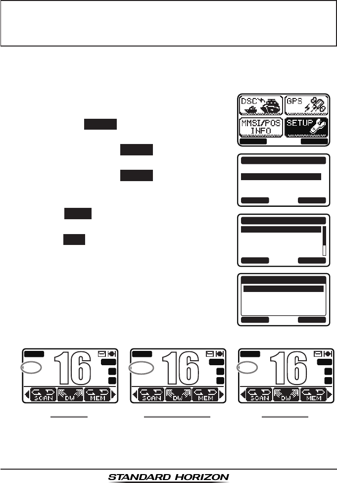
8.5 INTERNATIONAL, USA, AND CANADA MODE
To change the channel group from International to USA or Canada:
1. Press the MENU key to display the menu.
BACK SELECT
BACK SELECT
SETUP
DSC SETUP
CHANNEL SETUP
CONFIGURATION
BACK SELECT
CHANNEL SETUP
CHANNEL GROUP
WEATHER ALERT
MULTI WATCH
SCAN MEMORY
BACK ENTER
CHANNEL GROUP
USA
INTL
CAN
2. Select “SETUP” with the ▲ / ▼ / ◄ / ► keys,
then press the SELECT soft key.
3. Press the ▲ / ▼key to select “CHANNEL
SETUP”, then press the SELECT soft key.
4. Press the ▲ / ▼ key to select “CHANNEL
GROUP”, then press the SELECT soft key.
5. Press the ▲ / ▼ key to select desired
channel group “USA”, “INTL”, or “CAN”.
6. Press the ENTER soft key to store the select-
ed setting.
7. Press the BACK soft key to exit the menu.
Refer to the VHF MARINE CHANNEL CHART (page 103) for allocated
channels in each mode.
All channels are factory-programmed in accordance with International,
Industry Canada (Canada), and FCC (USA) regulations. Mode of op-
eration cannot be altered from simplex to duplex or vice-versa.
uSa MoDe
BUSY
MEM
A
C
USA
25W
P
16
InternatIonaL MoDe
BUSY
MEM
A
C
INTL
25W
P
16
CanaDa MoDe
BUSY
MEM
A
C
CAN
25W
P
16

Page 27GX1300
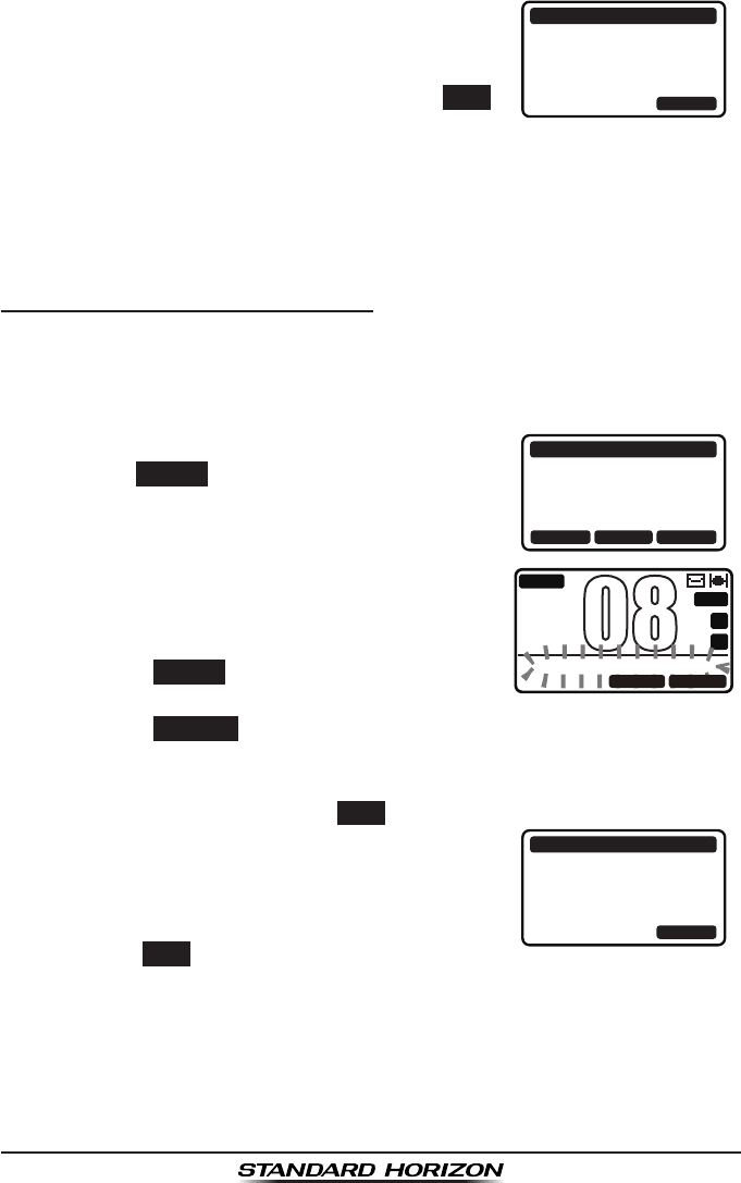
8.6 NOAA WEATHER CHANNELS
1. To receive a NOAA weather channel, press
one of the soft keys, then press the WX soft key
from any channel. The transceiver will go to
the last selected weather channel and the “WX”
icon appears on the display.
2. Rotate the CH knob to select a different NOAA weather channel.
3. To exit from the NOAA weather channels, press one of the soft keys,
then press the CH soft key. The transceiver returns to the channel it was
on prior to a weather channel and the “WX” icon disappears from the
display.
8.6.1 NOAA Weather Alert
In the event of extreme weather disturbances, such as storms and hurri-
canes, the NOAA (National Oceanic and Atmospheric Administration) sends
a weather alert accompanied by a 1050 Hz tone and subsequent weather
report on one of the NOAA weather channels.
The GX1300 can receive weather alerts when on a weather channel and on
the last selected weather channel during scanning modes or while on anoth-
er channel.
When an alert is received on a NOAA weather
channel, scanning will stop and the transceiver
will emit a loud beep to alert the user of a NOAA
broadcast. Press any key to stop the alert and
receive the weather report.
To disable the weather alert function, refer to section “10.2.2 Weather
Alert”.
8.6.2 NOAA Weather Alert Testing
NOAA tests the alert system ever Wednesday between 11AM and 1PM.
To test the GX1300’s NOAA weather feature, on Wednesday between 11AM
and 1PM, setup as in section “8.6.1 NOAA Weather Alert” and conrm the
alert is heard.
GX1300Page 28
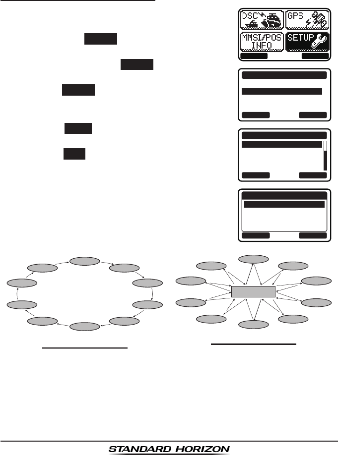
8.7 SCANNING
Allows the user to select the scan type from Memory scan or Priority scan.
“Memory scan” scans the channels that were programmed into memory.
“Priority scan” scans the channels programmed in memory with the priority
channel.
8.7.1 Selecting the Scan Type
1. Press the MENU key to display the menu.
BACK SELECT
BACK SELECT
SETUP
DSC SETUP
CHANNEL SETUP
CONFIGURATION
BACK SELECT
CHANNEL SETUP
SCAN TYPE
SCAN RESUME
PRIORITY CH
SUB CH
BACK ENTER
SCAN TYPE
PRIORITY SCAN
MEMORY SCAN
2. Select “SETUP” with the ▲ / ▼ / ◄ / ► keys,
then press the SELECT soft key.
3. Press the ▲ / ▼key to select “CHANNEL
SETUP”, then press the SELECT soft key.
4. Select “SCAN TYPE” with the ▲ / ▼ keys, then
press the SELECT soft key.
5. Press the ▲ / ▼ keys to select “PRIORITY
SCAN” or “MEMORY SCAN.”
6. Press the ENTER soft key to store the selected
setting.
7. Press the BACK soft key to exit the menu.
CH12
CH09
CH01A
CH15
CH18
CH22A
CH61A
CH68A
CH68A
CH88A
Priority Channel
CH12
CH09
CH01A
CH15
CH18
CH22A
CH61A
CH68A
CH68A
CH88A
MeMory SCan (M-SCan)PrIorIty SCan (P-SCan)
Page 29GX1300
8.7.2 Scan Memory Programming
1. Press the MENU key to display the menu.
BACK SELECT
BACK SELECT
SETUP
DSC SETUP
CHANNEL SETUP
CONFIGURATION
BACK SELECT
CHANNEL SETUP
WEATHER ALERT
MULTI WATCH
SCAN MEMORY
SCAN TYPE
BACK MEM
SCAN MEMORY
CH: 16
CH: 17
CH: 18A
CH: 19A
MEM
MEM
MEM
2. Select “SETUP” with the ▲ / ▼ / ◄ / ► keys,
then press the SELECT soft key.
3. Press the ▲ / ▼key to select “CHANNEL
SETUP”, then press the SELECT soft key.
4. Press the ▲ / ▼ key to select “SCAN MEMORY”,
then press the SELECT soft key.
5. Press the ▲ / ▼ key to select a desired
channel to be scanned, then press the MEM
soft key. “MEM” appears on the display, which
indicates the channel has been selected to the
scan channel.
6. Repeat step 5 for all the desired channels to
be scanned.
7. To delete a channel from the list, select the
channel then press the MEM soft key again.
The “MEM” disappears from the display.
8. Press the BACK soft key to exit the menu.
8.7.3 Memory Scanning (M-SCAN)
1. Adjust the SQL knob until background noise disappears.
2. Select “MEMORY SCAN” as scan type via the SETUP menu.
3. Press one of the soft keys, then press the SCAN
soft key (it may be necessary to press the ◄
/ ► key to locate the SCAN soft key). “M-SCN”
appears on the LCD. Scanning will proceed
from the lowest to the highest programmed
channel number and will stop on a channel
when a transmission is received.
BUSY
MEM
A
C
USA
25W
M-SCN
P
16
4. The channel number will blink during recep-
tion.
5. To stop scanning, press the 16/S key or press one of the soft keys, then
press the SCAN soft key.
GX1300Page 30
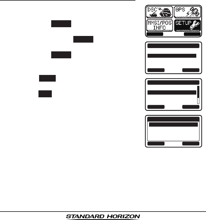
8.7.4 Priority Channel Setting
In the default setting, Channel 16 is set as the priority channel. You may
change the priority channel to another channel from Channel 16 via the
SETUP menu.
1. Press the MENU key to display the menu.
BACK SELECT
BACK SELECT
SETUP
DSC SETUP
CHANNEL SETUP
CONFIGURATION
BACK SELECT
CHANNEL SETUP
SCAN TYPE
SCAN RESUME
PRIORITY CH
SUB CH
BACK ENTER
PRIORITY CH
CH: 16
CH: 17
CH: 18A
CH: 19A
P-CH
2. Select “SETUP” with the ▲ / ▼ / ◄ / ► keys,
then press the SELECT soft key.
3. Press the ▲ / ▼key to select “CHANNEL
SETUP”, then press the SELECT soft key.
4. Press the ▲ / ▼ key to select “PRIORITY CH”,
then press the SELECT soft key.
5. Press the ▲ / ▼ keys to select the priority
channel.
6. Press the ENTER soft key to store the selected
setting.
7. Press the BACK soft key to exit the menu.
8.7.5 Priority Scanning (P-SCAN)
1. Adjust the SQL knob until background noise disappears.
2. Select “PRIORITY SCAN” as scan type via the SETUP menu.
3. Press one of the soft keys, then press the
SCAN soft key (it may be necessary to press
the ◄ / ► key to locate the SCAN soft key).
“P-SCN” appears on the LCD. Scanning will
proceed between the memorized channels and
the priority channel. The priority channel will
be scanned after each programmed channel.
BUSY
MEM
A
C
USA
25W
P-SCN
P
16
4. Scanning will stop on a channel when a trans-
mission is received. The channel number will
blink during reception.
5. To stop scanning, press the 16/S key or press one of the soft keys, then
press the SCAN soft key.
Page 31GX1300
8.8 MULTI WATCH (TO PRIORITY CHANNEL)
Multi watch is used to scan two or three channels for communications.
In Dual Watch, a normal VHF channel and the priority channel are
scanned alternately.
In Triple Watch, a normal VHF channel, the priority channel, and the sub
channel are scanned alternately.
When a signal is received on the normal channel the radio briefly switches
between the normal channel and the priority channel to look for a transmission.
If the radio receives communications on the priority channel the radio stops and
listens to the priority channel until communication ends and then starts dual or
triple watch scan again.
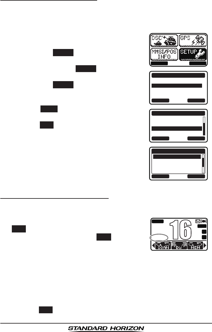
8.8.1 Setting up the Multi Watch Operation
1. Press the MENU key to display the menu.
BACK SELECT
BACK SELECT
SETUP
DSC SETUP
CHANNEL SETUP
CONFIGURATION
BACK SELECT
CHANNEL SETUP
WEATHER ALERT
MULTI WATCH
SCAN MEMORY
SCAN TYPE
BACK ENTER
MULTI WATCH
DUAL
TRIPLE
2. Select “SETUP” with the ▲ / ▼ / ◄ / ► keys,
then press the SELECT soft key.
3. Press the ▲ / ▼key to select “CHANNEL
SETUP”, then press the SELECT soft key.
4. Select “MULTI WATCH” with the ▲ / ▼ keys,
then press the SELECT soft key.
5. Press the ▲ / ▼ keys to select “DUAL” or
“TRIPLE.”
6. Press the ENTER soft key to store the selected
setting.
7. Press the BACK soft key to exit the menu.
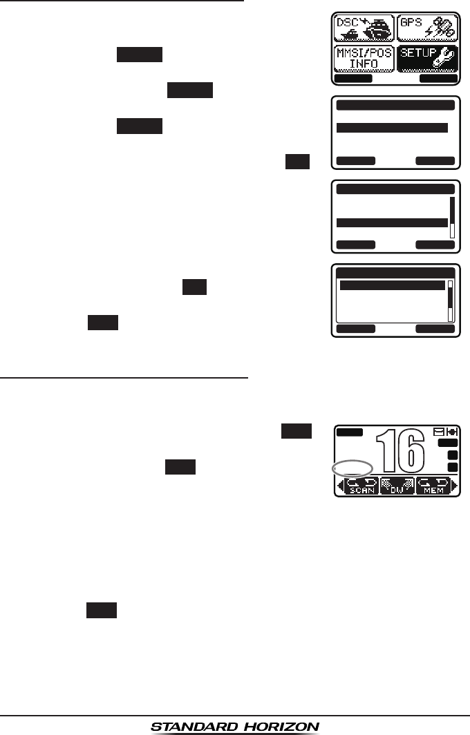
GX1300Page 32
8.8.2 Starting the Dual Watch
1. Adjust the SQL knob until the background noise disappears.
2. Select the channel you wish to dual watch to the priority channel.
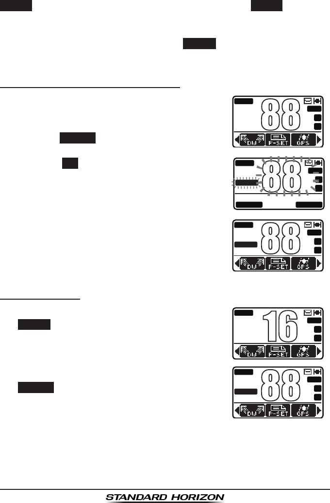
3. Press one of the soft keys, then press the DW
soft key (it may be necessary to press the ◄ /
► key to locate the DW soft key).
“
DW-##” (## indicates the priority channel
number you have selected) appears on the
LCD. The radio will scan between the priority
channel and the channel that was selected in
step 2.
If a transmission is received on the channel
selected in step 2, the GX1300 will dual watch
to the priority channel.
BUSY
MEM
A
C
P-SET
USA
25W
DW-16
A
88
4. To stop dual watch, press one of the soft keys, then press the DW soft
key again.
When selecting “TRIPLE” in the SETUP menu, TW will be displayed as the
soft key instead of DW.
NOTE
The priority channel may be changed from CH16 to another channel.
Refer to section “8.6.4 Priority Channel Setting”.
Page 33GX1300
8.9 PRESET CHANNELS: INSTANT ACCESS
8 preset channels can be programmed for instant access. Pressing the
PRESET soft key activates the preset channel bank. If the PRESET soft key is
pressed and no channels have been assigned, an alert beep will be emitted
from the speaker.
For details about the assignment of the PRESET and other soft keys, see
“10.1.7 Soft Keys”.
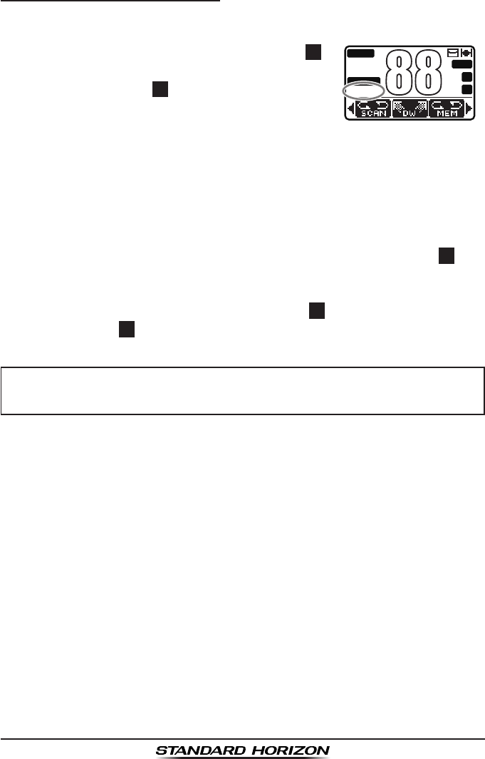
8.9.1 Preset Channel Programming
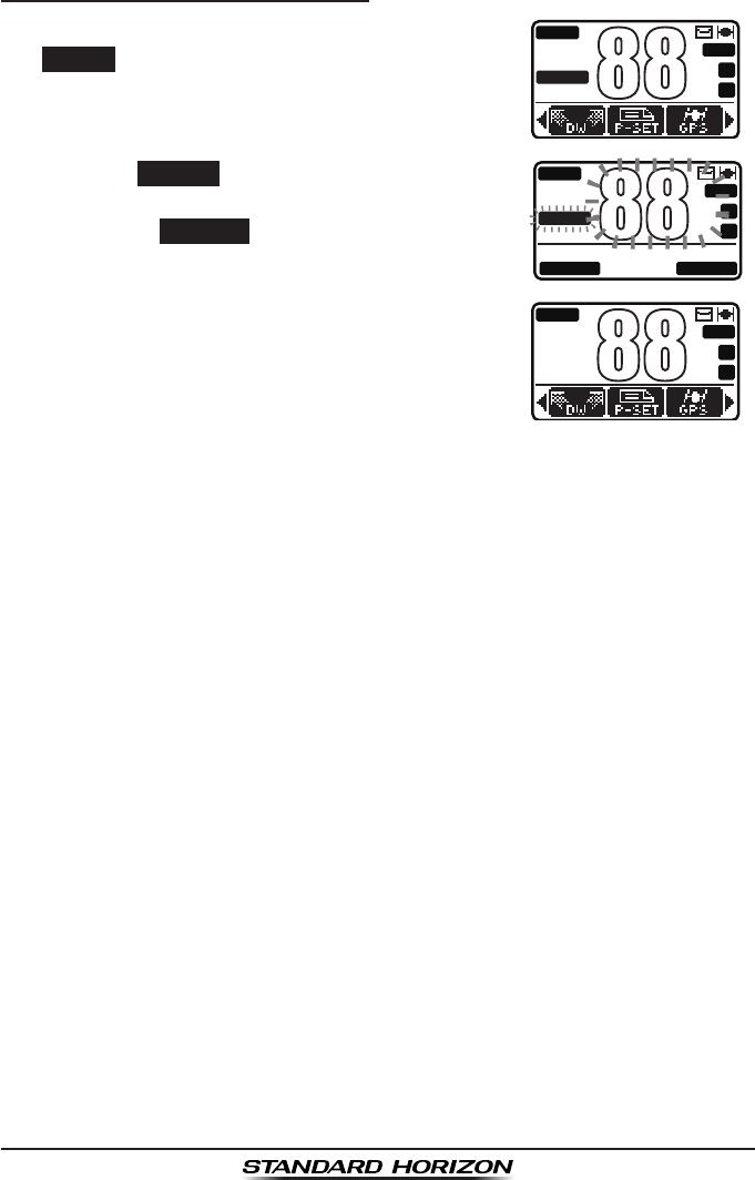
1. Press the ▲ / ▼ key to select the channel to
be programmed.
BUSY
MEM
A
C
USA
25W
A
88
BUSY
MEM
A
C
P-SET
USA
25W
A
88
QUIT ADD
BUSY
MEM
A
C
P-SET
USA
25W
A
88
2. Press one of the soft keys, then press and
hold the PRESET soft key until the channel
number blinks.
3. Press the ADD soft key to program the channel
into the preset channel.
The “P-SET” icon appears on the LCD.
4. Repeat steps 1 through 3 to program the
desired channels into the preset channel bank.
8.9.2 Operation
1. Press one of the soft keys, then press the
PRESET soft key to recall the preset channel.
The “P-SET” icon will appear on the LCD.
BUSY
MEM
A
C
USA
25W
P
16
BUSY
MEM
A
C
P-SET
USA
25W
A
88
2. Press the ▲ / ▼ key to select the desired
preset channel.
3. Press one of the soft keys, then press the
PRESET soft key again to return to the last
selected channel.
GX1300Page 34
8.9.3 Deleting a Preset Channel
1. Press one of the soft keys, then press the
PRESET soft key.
BUSY
MEM
A
C
P-SET
USA
25W
A
88
BUSY
MEM
A
C
P-SET
USA
25W
A
88
QUIT DELETE
BUSY
MEM
A
C
USA
25W
A
88
2. Press the ▲ / ▼ key to select the preset
channel to be deleted.
3. Press one of the soft keys, then press and
hold the PRESET soft key until the channel
number blinks.
4. Press the DELETE
soft key to delete the
channel from the preset channel bank.
The “P-SET” icon disappears on the LCD.
5. Repeat steps 2 through 4 to delete the desired
channels from the preset channel bank.

Page 35GX1300
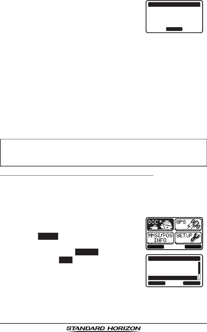
8.10 OPERATION MENU
The GX1300 provides advanced features below,
via the menu screen displayed by pressing the
MENU key on the front panel.
BACK SELECT
DSC
The following seven types of DSC (Digital Selective Calling) are available:
Individual, Group, All Ships, Position Request, Position Report, Polling, and
Auto Position Polling.
This menu also provides convenient functions for DSC as below.
Sets the nature of Distress Call (DIST ALERT MSG)
Browses information of received DSC calls (DSC LOG)
Transmits a test call (DSC TEST)
GPS
You can check the signal strength of captured GPS satellites.
MMSI/POS INFO
Via this menu, input your MMSI (Maritime Mobile Service Identity) before you
use DSC.
SETUP
This menu allows certain aspects of your transceiver’s conguration to be
customized for your personal operating conditions.

GX1300Page 36
9 DIGITAL SELECTIVE CALLING
9.1 GENERAL
WARNING
Digital Selective Calling (DSC) is a semi-automated method of establishing a
radio call. It has been designated by the International Maritime Organization
(IMO) as an international standard for establishing VHF, MF, and HF radio
calls. It has also been designated as part of the Global Maritime Distress and
Safety System (GMDSS). It is planned that DSC will eventually replace aural
watches on distress frequencies and will be used to announce routine and
urgent maritime safety information broadcasts.
This system allows mariners to instantly send a distress call with GPS
position (when connected to the transceiver) to the Coast Guard and other
vessels within range of the transmission. DSC will also allow mariners to
initiate or receive Distress, Urgency, Safety, Routine, POSITION REQUEST,
POSITION SEND, and Group calls to or from another vessel equipped with a
DSC transceiver.
9.2 MARITIME MOBILE SERVICE IDENTITY (MMSI)
9.2.1 What is an MMSI?
An MMSI is a nine digit number used on Marine radios capable of using
Digital Selective Calling (DSC). This number is used like a telephone number
to selectively call other vessels.
THIS NUMBER MUST BE PROGRAMMED INTO THE RADIO TO
OPERATE DSC FUNCTIONS.
How can I obtain an MMSI assignment?
Please contact the Radio Licensing Authority for your country for information
on how to obtain an MMSI number.
The GX1300 is designed to generate digital maritime distress and
safety calls to facilitate search and rescue. To be effective as a safety
device, this equipment must be used only within communication range
of a shore-based VHF marine channel 70 distress and safety watch
system. The range of signal may vary, however under normal condi-
tions should be approximately 20 nautical miles.
Page 37GX1300
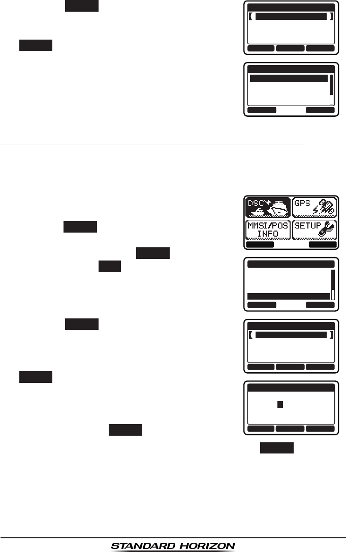
9.2.2 Programming the MMSI
WARNING
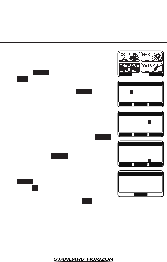
1. Press the MENU key to display the menu.
BACK SELECT
MMSI INPUT
1st:
---------
BACK FINISH SELECT
MMSI INPUT
1st:
366901234
BACK SELECTFINISH
MMSI INPUT
1st:
*********
366901234
2nd:
BACK SELECTFINISH
MMSI INPUT
STORED MMSI
366901234
OK
2. Press the ▲ / ▼ key to select “MMSI/POS
INFO”.
3. Press the SELECT soft key. (To cancel, press
the BACK soft key.)
4. Press the ▲ / ▼ key to select the rst number
of your MMSI, then press the SELECT soft key
to step to the next number.
5. Repeat step 4 to set your MMSI number (nine
digits).
6. If a mistake was made entering in the MMSI
number, press the ◄ / ► key until the wrong
number is highlighted, then press the ▲ / ▼
key to correct the entry and press the SELECT
soft key.
7. When finished programming the MMSI
number, press the FINISH soft key. The radio
will ask you to input the MMSI number again.
Use steps 4 through 6 above.
8. After the second number has been input, press
the FINISH soft key to store the MMSI.
9. Press the OK soft key to return to the “MMSI/
POS INFO” screen.
10. Press the 16/S key or press the BACK soft key to return to radio opera-
tion mode.
The MMSI can be input only once. Therefore, please be careful
not to input the incorrect MMSI number. If you need to change the
MMSI number after it has been entered, the radio will have to be re-
turned to Factory Service. Refer to the section “12.2 FACTORY SER-
VICE.”
GX1300Page 38
9.3 DSC DISTRESS ALERT
The GX1300 is capable of transmitting and receiving DSC distress messag-
es to all DSC radios. The GX1300 may be connected to a GPS to also trans-
mit the latitude and longitude of the vessel.
NOTE
9.3.1 Transmitting a DSC Distress Alert
NOTE
In order for your vessel's location to be transmitted, either connect a GPS to
the GX1300 (refer to section “6.4 ACCESSORY CABLE”) or manually input
your position (refer to section “9.9 MANUAL INPUTTING OF THE GPS
LOCATION”).
Basic Operation
1. Lift the red spring loaded DISTRESS cover,
then press and hold the DISTRESS key. The
“DISTRESS” screen will appear on the LCD
and the radios display will count down (3sec
2sec 1sec) and then the distress alert
will be transmitted. The backlight of the LCD
and keypad ashes while the radios display is
counting down.
QUIT
!!DISTRESS!!
UNDESIGNATED
[DISTRESS]
Hold for 3 sec.
!!DISTRESS!!
UNDESIGNATED
[ Transmitting ]
!!DISTRESS!!
UNDESIGNATED
[Waiting for ACK]
TX IN: 02:25
PAUS
EI
NFOCANCEL
2. The GX1300 watches for an acknowledgment
call on channel 70 or a voice call on channel
16 from another vessel.
3. If an vessel responds to you on channel 16,
pick up the microphone and press and hold the
PTT switch to advise your distress situation.
If a GPS with NMEA output is not connected to the radio, the GX1300
will beep 10 minutes after the radio is turned on and will continue to
beep every 4 hours alerting to connect a GPS.
To be able to transmit a DSC distress alert, an MMSI number must be
programmed (refer to section “9.2.2 Programming the MMSI”).
Page 39GX1300
4. When a DSC distress acknowledgment is
received on channel 70, a DSC distress alarm
sounds and channel 16 is automatically select-
ed. Pick up the microphone and press and
hold the PTT switch to advise your distress
situation.
!!DISTRESS!!
RX ACKNOWLEDGED
USCG CA
SINCE: 00:15
OK
The LCD shows either of the following messages depending on the
received acknowledgement:
RX ACKNOWLEDGED: acknowledgment signal is received.
RX RLY ACK: relay acknowledgment signal is received from
another vessel or coast station.
To cancel the DSC distress alarm signal from the speaker, press any
key.
5. If no acknowledgment is received, the distress alert is repeated at
approximately 4 minute intervals until a DSC acknowledgment is
received.
NOTE
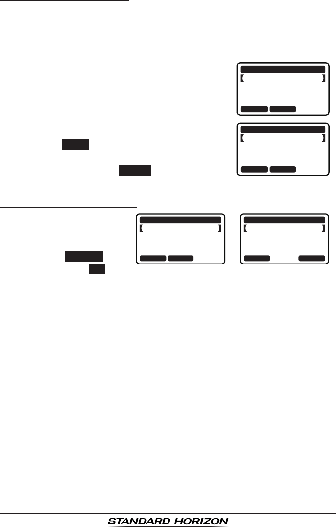
Transmitting a DSC Distress Alert with Nature of Distress
The GX1300 is capable of transmitting a DSC distress alert with the following
“Nature of Distress” categories:
Undesignated, Fire, Flooding, Collision, Grounding, Capsizing, Sinking,
Adrift, Abandoning, Piracy, MOB
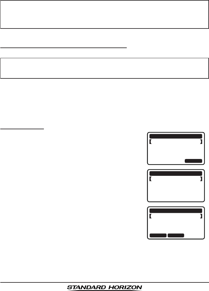
1. Press the MENU key to display the menu.
BACK SELECT
BACK SELECT
DSC CALL
INDIVIDUAL
GROUP
ALL SHIPS
DIST ALERT MSG
2. Press the ▲ / ▼ keys to select “DSC”, then
press the SELECT soft key.
3. Press the ▲ / ▼ keys to select “DIST ALT
MSG”, then press the SELECT soft key. (To
cancel, press the BACK soft key.)
After the radio transmits the distress call, the display of the radio will
show the remaining time until the distress call will be re-transmitted.
The display will show “TX IN 04:00” and count down.
GX1300Page 40
4. Press the NATURE soft key.
BACK POS/TM
DIST ALERT MSG
UNDESIGNATED
POS: --°--.----
---°--.----
TIME: --:--UTC
NATURE
BACK SELECT
NATUER OF DIST
FIRE,EXPLOSION
FLOODING
COLLISION
GROUNDING
5. Press the ▲ / ▼ keys to select the desired
nature of distress category, then press the
SELECT soft key.
6. Press and hold the DISTRESS key until a
distress alert is transmitted.
7. Perform the steps 2 through 5 of the basic
operation described in the previous section.
Transmitting a DSC Distress Alert with Manually Entering a Position
When the GX1300 is not connected to a GPS receiver or the GPS is not
operating properly, you may input the latitude/longitude of your vessel
manually at your sending of a DSC distress alert.
1. Press the MENU key to display the menu.
BACK SELECT
BACK SELECT
DSC CALL
INDIVIDUAL
GROUP
ALL SHIPS
DIST ALERT MSG
2. Press the ▲ / ▼ keys to select “DSC”, then
press the SELECT soft key.
3. Press the ▲ / ▼ keys to select “DIST ALT
MSG”, and then press the SELECT soft key. (To
cancel, press the BACK soft key.)
4. Press the POS/TM soft key.
BACK POS/TM
DIST ALERT MSG
UNDESIGNATED
POS: --°--.----
---°--.----
TIME: --:--UTC
NATURE
POS AND TIME
23°56.890N
123°56.890W
POS:
TIME: 12:56UTC
BACK SELECTFINISH
5. Enter the latitude/longitude of your vessel and
UTC time in the 24-hour format. Press the ▲
/ ▼ keys to select the number and press the
SELECT soft key to move the cursor to the next
character. If you make a mistake, press the ◄
/ ► key until the wrong character is highlight-
ed, then press the ▲ / ▼ key to correct the
entry and press the SELECT soft key.
6. When you have completed your selection, press the FINISH soft key to
save the setting.
7. Press and hold the DISTRESS key until a distress alert is transmitted.
8. Perform the steps 2 through 5 of the basic operation described in the
previous section.
Page 41GX1300
Pausing a DSC Distress Alert
After a DSC distress call is transmitted, it is repeated every 4 minutes until
the call is canceled by the user or until the radio is turned off and on again.
The GX1300 has provision to suspend (pause) the re-transmitting of the
distress call by the procedure below.
1. After the distress call is transmitted, the radio
will show the display as on the right.
Looking at this display you will notice “TX in
02:25”, this is the time when the radio will
re-transmit the distress call.
!!DISTRESS!!
UNDESIGNATED
[Waiting for ACK]
TX IN: 02:25
PAUS
EI
NFOCANCEL
!!DISTRESS!!
UNDESIGNATED
Retransmission
is now pausing!
TX IN: 02:25
RESUM
EI
NFOCANCEL
2. To suspend re-transmitting the distress call,
press the PAUSE soft key.
3. To resume counting down to transmit the
distress call, press the RESUME soft key.
Canceling a DSC Distress Alert
The GX1300 has the
capability to transmit a
DSC distress cancel call by
pressing the CANCEL soft
key, then press the YES soft
key.
!!DISTRESS!!
UNDESIGNATED
[Waiting for ACK]
TX IN: 02:25
PAUS
EI
NFOCANCEL
!!DISTRESS!!
UNDESIGNATED
Do you want to
cancel a DIST?
YE
SN
O
GX1300Page 42
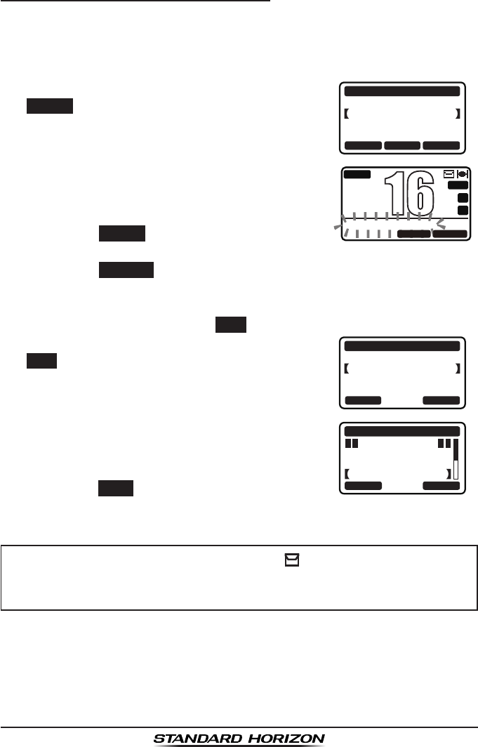
9.3.2 Receiving a DSC Distress Alert
1. When a DSC distress alert is received, an emergency alarm sounds.
The display will show the MMSI (or name) of the vessel transmitting the
distress.
2. Press any key on the radio to stop the alarm.
3. To immediately switch to channel 16, press the
ACCEPT soft key.
If a key is not pressed for thirty seconds (by
default; refer to the section “10.3.8 Auto
Channel Switching Time”) after a DSC call is
received, the GX1300 will automatically switch
to channel 16 for you to monitor distress
communications.
RX DISTRESS
YAESU
UNDESIGNATED
NOT ACKNOWLEDGED
SINCE: 00:05
ACCEPT QUITPAUSE
BUSY
MEM
A
C
USA
25W
DISTRESS PAUSE
P
16
QUITRESUME
4. Press the PAUSE
soft key to suspend the
acknowledgement.
Press the RESUME
soft key to resume the
acknowledgement.
5. If you want the radio to stay on the channel you were on before receiv-
ing the distress call, press the QUIT soft key.
6. After accepting the distress call, press the
INFO soft key to show information of the vessel
in distress.
RX DISTRESS
YAESU
UNDESIGNATED
NOT ACKNOWLEDGED
SINCE: 00:05
INFO QUITINFO
DIST INFO
DIST: 366901234
YAESU
UNDESIGNATED
RX DISTRESS
BACK QUIT
7. Press the ▲ / ▼ keys to scroll the screen and
see the MMSI (or name), nature of distress,
and GPS position of the vessel in distress.
If the received call does not include position
data, the LCD will show “NO POSITION”.
9. Press the QUIT soft key to return to radio
operation mode.
NOTE
When there is an unread distress alert, “ ” icon will appear on the
display. You may review the unread distress alert from the DSC log,
refer to the section “9.12.2 Reviewing a Logged DSC Distress Call.”
Page 43GX1300
9.4 ALL SHIPS CALL
The all ships call function allows contact to be established with other vessel
stations without having their ID in the individual calling directory. Also, priority
for the call can be designated as "urgency" or "safety".
URGENCY Call: This type of call is used when a vessel may not truly be
in distress, but has a potential problem that may lead to a
distress situation. This call is the same as saying “PAN PAN,
PAN PAN, PAN PAN” on channel 16.
SAFETY Call: This type of call is used to transmit boating safety informa-
tion to other vessels. This message usually contains infor-
mation about an overdue boat, debris in the water, loss of a
navigation aid or an important meteorological message. This
call is the same as saying “Securite, Securite, Securite.”
9.4.1 Transmitting an All Ships Call
1. Press the MENU key to display the menu.
BACK SELECT
BACK SELECT
DSC CALL
INDIVIDUAL
GROUP
ALL SHIPS
DIST ALERT MSG
2. Press the ▲ / ▼ keys to select “DSC”, then
press the SELECT soft key.
3. Press the ▲ / ▼ keys to select “ALL SHIPS”,
and then press the SELECT
soft key. (To
cancel, press the BACK soft key.)
4. Press the ▲ / ▼ keys to select the category
of the call (“SAFETY” or “URGENCY”), then press
the SELECT soft key.
BACK SELECT
CATEGORY
SAFETY
URGENCY
5. Press the ▲ / ▼ keys to select the operating
channel you want to communicate on, then
press the SELECT soft key.
BACK SELECT
INTERSHIP CH
CH:16
CH:06
CH:08
CH:09
6. Press the YES soft key to transmit the selected
type of all ships call.
YE
SN
O
ALL SHIPS
CATEG: SAFETY
CH: 16
Transmit a Call?
GX1300Page 44
7. After the all ships call is transmitted, the trans-
ceiver will switch to the channel which select-
ed on the step 5 above, with no change of the
display. To change the display, press the QUIT
soft key.
ALL SHIPS
CATEG: SAFETY
SINCE: 00:05
[ Transmitted ]
QUIT
8. Listen to the channel to make sure it is not busy, then key the micro-
phone and say “PAN PAN, PAN PAN, PAN PAN” or “Securite, Securite,
Securite” depending on the priority of the call. Say your call sign and
announce the channel you wish to switch to for communications.
9.4.2 Receiving an All Ships Call
1. When an all ships call is received, an emergency alarm sounds.
The display will show the MMSI (or name) of the vessel transmitting the
all ships call.
2. Press any key on the radio to stop the alarm.
3. To immediately switch to requested channel,
press the ACCEPT soft key.
If a key is not pressed for thirty seconds (by
default; refer to the section “10.3.8 Auto
Channel Switching Time”) after an all ships
call is received, the GX1300 will automatically
switch to the requested channel for you to
monitor communications.
RX ALL SHIPS
YAESU
CATEG: SAFETY
CH: 08
SINCE: 00:05
ACCEPT QUITPAUSE
BUSY
MEM
A
C
USA
25W
08
ALL SHIPS PAUSE
QUITRESUME
4. Press the PAUSE
soft key to suspend the
acknowledgement.
Press the RESUME
soft key to resume the
acknowledgement.
5. If you want the radio to stay on the channel you were on before receiv-
ing the all ships call, press the QUIT soft key.
6. Press the ▲ / ▼ keys to scroll the screen and
see the MMSI (or name) of the calling vessel,
category of the call and requested operating
channel.
RX ALL SHIPS
YAESU
CATEG: SAFETY
CH: 08
SINCE: 00:08
ABLE QUITUNABLE
7. Press the QUIT soft key to display the operat-
ing channel number of the requested channel.
8. Press the PTT switch on the microphone and talk to the calling vessel.

Page 45GX1300
9.4.3 Setting up the All Ships Call Ringer
The GX1300 has the capability to turn off the all ships call ringer.
1. Press the MENU key to display the menu.
BACK SELECT
BACK SELECT
SETUP
DSC SETUPGROUP
CHANNEL SETUP
CONFIGURATION
2. Press the ▲ / ▼ keys to select “SETUP”, then
press the SELECT soft key.
3. Press the ▲ / ▼ keys to select “DSC SETUP”,
then press the SELECT soft key. (To cancel,
press the BACK soft key.)
4. Select “DSC BEEP” with the ▲ / ▼ keys, then
press the SELECT soft key.
BACK SELECT
DSC SETUP
AUTO POS POLL
AUTO POS TIME
CH SWITCH TIMER
DSC BEEP
5. Select “ALL SHIPS” with the ▲ / ▼ keys, then
press the SELECT soft key.
BACK SELECT
DSC BEEP
INDIVIDUAL
GROUP
ALL SHIPS
POS REQUEST
ON
ON
ON
OFF
6. Press the ▲ / ▼ keys to select “OFF”, then
press the ENTER soft key.
BACK ENTER
ALL SHIPS
OFF
ON
7. Press the 16/S key or press the BACK soft key to return to radio opera-
tion mode.
If you wish to return to enabling the ringer tone, just repeat the above proce-
dure, pressing the ▲ / ▼ keys to select “ON” in step 6 above.
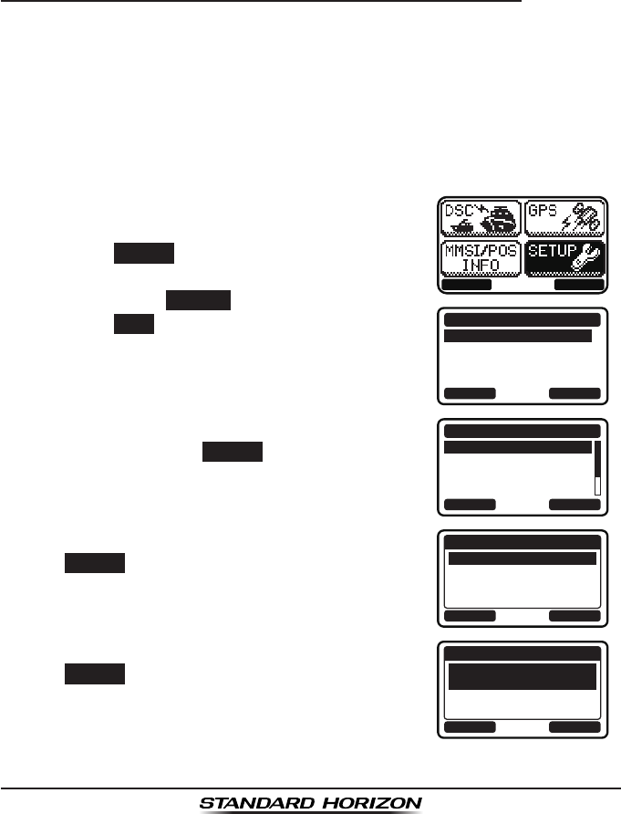
GX1300Page 46
9.5 INDIVIDUAL CALL
This feature allows the GX1300 to contact another vessel with a DSC VHF
radio and automatically switch the receiving radio to a desired communica-
tions channel. This feature is similar to calling a vessel on CH16 and request-
ing to go to another channel (switching to the channel is private between the
two stations).
9.5.1 Setting up the Individual / Position Call Directory
The GX1300 has a DSC directory that allows you to store a vessel or
person’s name and the MMSI (Maritime Mobile Service Identity Number)
number associated with vessels you wish to transmit individual calls, position
requests and position report transmissions. The GX1300 can store up to 60
individual MMSI numbers with vessel's or person's names.
To transmit an Individual call you must program this directory with the infor-
mation of the persons you wish to call, similar to a cellular phones directory.
1. Press the MENU key to display the menu.
BACK SELECT
BACK SELECT
SETUP
DSC SETUPGROUP
CHANNEL SETUP
CONFIGURATION
2. Press the ▲ / ▼ keys to select “SETUP”, then
press the SELECT soft key.
3. Press the ▲ / ▼ keys to select “DSC SETUP”,
then press the SELECT soft key. (To cancel,
press the BACK soft key.)
4. Select “INDIVIDUAL DIR.” with the ▲ / ▼
keys, then press the SELECT soft key.
BACK SELECT
DSC SETUP
INDIVIDUAL DIR.
INDIVIDUAL REPLY
INDIVIDUAL ACK
INDIVIDUAL RING
5. Select “ADD” with the ▲ / ▼ keys, then press
the SELECT soft key.
BACK SELECT
INDIVIDUAL DIR.
ADD
EDIT
DELETE
6. Select “NAME” with the ▲ / ▼ keys, then press
the SELECT soft key.
BACK SELECT
ADD
NAME:
-------------
MMSI:
---------
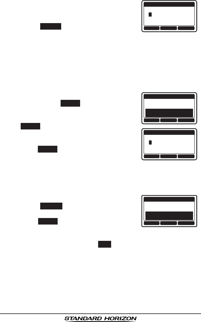
Page 47GX1300
7. Press the ▲ / ▼ keys to scroll to the rst letter
of the name of the vessel or person you want
to list in the directory.
BACK SELECTFINISH
ADD
NAME:
Y--------------
8. Press the SELECT soft key to store the first
letter of the name and step to the next letter to
the right.
9. Repeat steps 7 and 8 until the name is complete.
Press the ► key to move to the next space if you want to enter a blank
space in the name.
If a mistake was made entering in the name, press the ◄ / ► keys
repeatedly until the wrong letter is highlighted, then press the ▲ / ▼
keys to correct the entry.
10. After the eleventh letter or space has been
entered, press the FINISH soft key to return to
the previous screen.
ADD
NAME:
YAESU-------
MMSI:
---------
BACK SELECTFINISH
BACK SELECTFINISH
ADD
MMSI:
3----------
11. Select “MMSI” with the ▲ / ▼ keys, then press
the SELECT soft key.
12. Press the ▲ / ▼ keys to scroll through
numbers, 0 to 9.
13. Press the SELECT soft key to store the number
and step to the next digit to the right.
14. Repeat steps 12 and 13 until the MMSI is complete.
If a mistake was made entering in the MMSI number, press the ◄ / ►
keys repeatedly until the wrong number is highlighted, then press the ▲
/ ▼ keys to correct the entry.
15. After the nineth number has been entered,
press the FINISH soft key to return to the
previous screen.
ADD
NAME:
YAESU-------
MMSI:
366901555
BACK SELECTFINISH
16. Press the FINISH soft key to save the entered
address.
17. To enter another individual address, repeat steps 5 through 16.
18. Press the 16/S key or press the BACK soft key to return to radio opera-
tion mode.
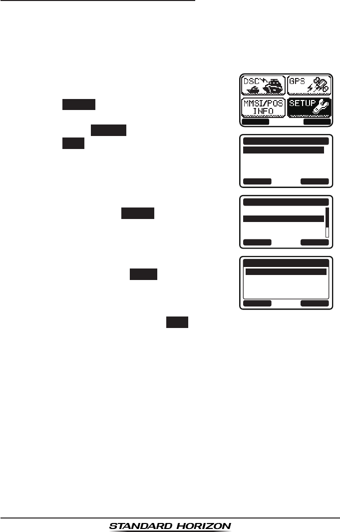
GX1300Page 48
9.5.2 Setting up Individual Call Reply
Allows setting up the radio to automatically (default setting) or manually
respond to a DSC individual call requesting you to switch to a working
channel for voice communications. When the manual response is selected
the MMSI of the calling vessel is shown allowing you to see who is calling.
This function is similar to caller ID on a cellular phone.
1. Press the MENU key to display the menu.
BACK SELECT
BACK SELECT
SETUP
DSC SETUPGROUP
CHANNEL SETUP
CONFIGURATION
2. Press the ▲ / ▼ keys to select “SETUP”, then
press the SELECT soft key.
3. Press the ▲ / ▼ keys to select “DSC SETUP”,
then press the SELECT soft key. (To cancel,
press the BACK soft key.)
4. Press the ▲ / ▼ keys to select “INDIVIDUAL
REPLY”, then press the SELECT soft key.
BACK SELECT
DSC SETUP
INDIVIDUAL DIR.
INDIVIDUAL REPLY
INDIVIDUAL ACK
INDIVIDUAL RING
5. Press the ▲ / ▼ keys to select “AUTO” or
“MANUAL”, then press the ENTER soft key.
BACK ENTER
INDIVIDUAL REPLY
AUTO
MANUAL
6. Press the 16/S key or press the BACK soft key to return to radio opera-
tion mode.
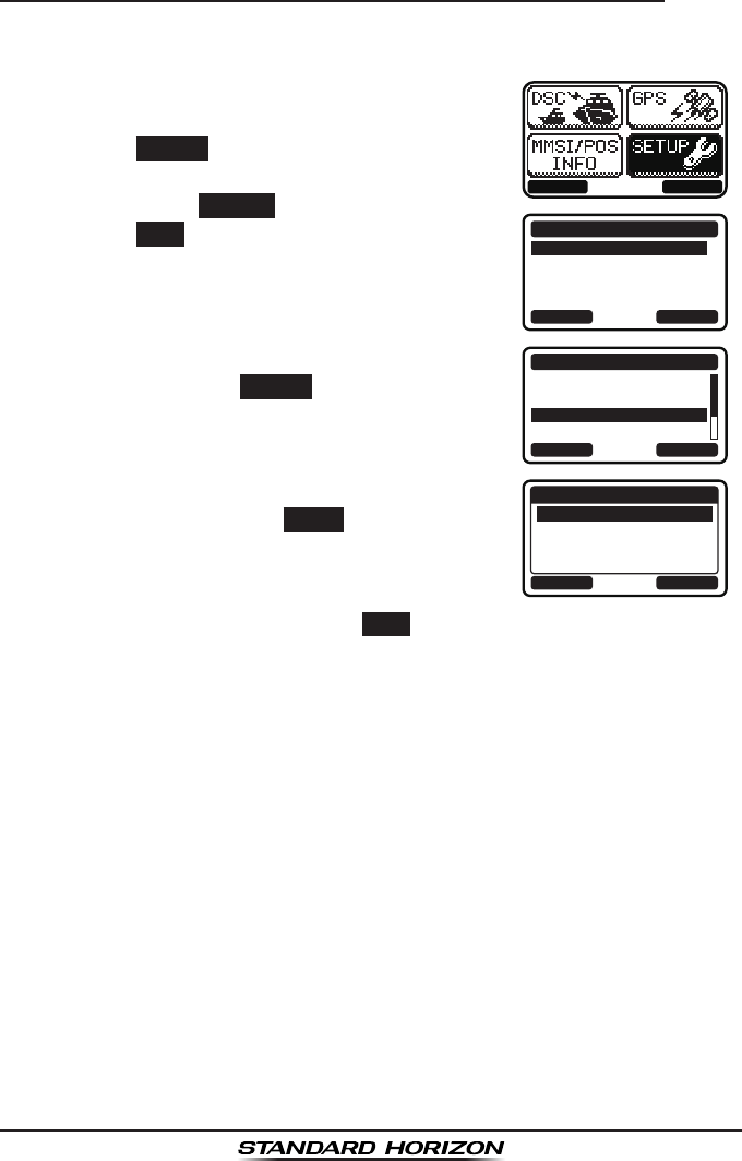
Page 49GX1300
9.5.3 Setting up the Individual Call Acknowledge Message
The GX1300 can select either reply message “Able” (default) or “Unable”
when the individual reply setting (described previous section) is set to “AUTO”.
1. Press the MENU key to display the menu.
BACK SELECT
BACK SELECT
SETUP
DSC SETUPGROUP
CHANNEL SETUP
CONFIGURATION
2. Press the ▲ / ▼ keys to select “SETUP”, then
press the SELECT soft key.
3. Press the ▲ / ▼ keys to select “DSC SETUP”,
then press the SELECT soft key. (To cancel,
press the BACK soft key.)
4. Press the ▲ / ▼ keys to select “INDIVIDUAL
ACK”, then press the SELECT soft key.
BACK SELECT
DSC SETUP
INDIVIDUAL DIR.
INDIVIDUAL REPLY
INDIVIDUAL ACK
INDIVIDUAL RING
5. Press the ▲ / ▼ keys to select “ABLE” or
“UNABLE”, then press the ENTER soft key.
BACK ENTER
INDIVIDUAL ACK
ABLE
UNABLE
6. Press the 16/S key or press the BACK soft key to return to radio opera-
tion mode.
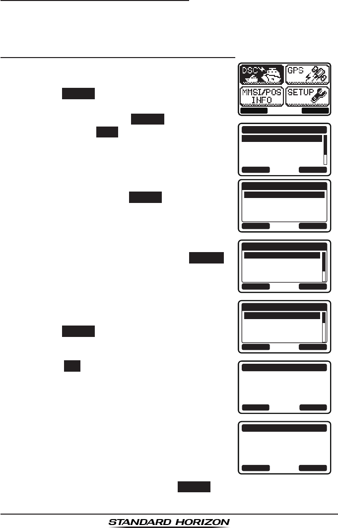
GX1300Page 50
9.5.4 Transmitting an Individual Call
This feature allows you to contact another vessel, switch their radio to a
requested working channel and ring like a telephone. This feature is similar
to calling a vessel on CH16 and requesting to go to another channel.
Individual Call from Individual / Position Call Directory
1. Press the MENU key to display the menu.
BACK SELECT
BACK SELECT
DSC CALL
INDIVIDUAL
GROUP
ALL SHIPS
DIST ALERT MSG
2. Press the ▲ / ▼ keys to select “DSC”, then
press the SELECT soft key.
3. Press the ▲ / ▼ keys to select “INDIVIDU-
AL”, and then press the SELECT soft key. (To
cancel, press the BACK soft key.)
4. Press the ▲ / ▼ keys to select “HISTORY” or
“MEMORY”, then press the SELECT soft key.
BACK SELECT
INDIVIDUAL
HISTORY
MEMORY
NEW ID
5. Press the ▲ / ▼ keys to select an individual
you want to contact, then press the SELECT
soft key.
BACK SELECT
MEMORY
YAESU
USCG
MEMORY SHIPS
HORIZON
6. Press the ▲ / ▼ keys to select the operat-
ing channel you want to communicate on and
press the SELECT soft key.
BACK SELECT
INTERSHIP CH
CH:06
CH:08
CH:09
CH:10
7. Press the YES soft key to transmit the individu-
al DSC signal.
INDIVIDUAL
YAESU
CATEG: ROUTINE
CH: 08
Transmit a Call?
YE
SN
O
8. After an individual call is transmitted, if the
reply signal is not received, “Waiting for
ACK” is shown on the display which means the
GX1300 is waiting for the vessel you called to
send an acknowledgement.
INDIVIDUAL
YAESU
CH: 08
SINCE: 00:05
[Waiting for ACK]
RESEND QUIT
To transmit the call again, press the RESEND soft key.
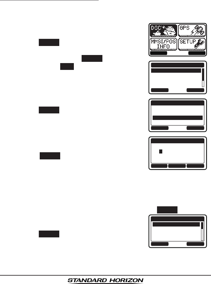
Page 51GX1300
9. When the GX1300 receives an acknowledgement from the vessel you
called, the radio will automatically switch to the operating channel select-
ed in step 6 and produce a ringing sound.
10. Key the microphone and call the other vessel you desire to communi-
cate with.
Individual Call - Manual MMSI Entry
You may enter an MMSI number manually to contact a vessel without storing
the MMSI in the individual/position call directory.
1. Press the MENU key to display the menu.
BACK SELECT
BACK SELECT
DSC CALL
INDIVIDUAL
GROUP
ALL SHIPS
DIST ALERT MSG
2. Press the ▲ / ▼ keys to select “DSC”, then
press the SELECT soft key.
3. Press the ▲ / ▼ keys to select “INDIVIDU-
AL”, and then press the SELECT soft key. (To
cancel, press the BACK soft key.)
4. Press the ▲ / ▼ keys to select “NEW ID”, then
press the SELECT soft key.
BACK SELECT
INDIVIDUAL
HISTORY
MEMORY
NEW ID
5. Press the ▲ / ▼ keys to scroll through
numbers, 0 to 9.
BACK SELECTFINISH
NEW ID
MMSI:
3----------
6. Press the SELECT soft key to store the number
and step to the next digit to the right.
7. Repeat steps 5 and 6 until the MMSI is complete.
If a mistake was made entering in the MMSI number, press the ◄ / ►
keys repeatedly until the wrong number is highlighted, then press the ▲
/ ▼ keys to correct the entry.
8. After the nineth number has been entered, press the FINISH soft key.
9. Press the ▲ / ▼ keys to select the operat-
ing channel you want to communicate on and
press the SELECT soft key.
BACK SELECT
INTERSHIP CH
CH:06
CH:08
CH:09
CH:10

GX1300Page 52
10. Press the YES soft key to transmit the individu-
al DSC signal.
INDIVIDUAL
366901555
CATEG: ROUTINE
CH: 08
Transmit a Call?
YE
SN
O
11. After an individual call is transmitted, if the reply signal is not received,
“Waiting for ACK” is shown on the display which means the GX1300
is waiting for the vessel you called to send an acknowledgement.
To transmit the call again, press the RESEND soft key.
12. When the GX1300 receives an acknowledgement from the vessel you
called, the radio will automatically switch to the operating channel select-
ed in step 9 and produce a ringing sound.
13. Key the microphone and call the other vessel you desire to communi-
cate with.
9.5.5 Receiving an Individual Call
When receiving an individual call, an acknowledgment must be sent back
to the calling station. The GX1300 in the default setting will automatically
respond to the calling station and switch to the requested channel for voice
communications. Refer to the section “9.5.2 Setting up Individual Call
Reply” if you want to change the setting to see who is calling before replying
to the call.
Automatic reply:
1. When an individual call is received, a ringing alarm sounds.
The GX1300 automatically switches to the requested channel. The
display shows the MMSI or the name of the vessel transmitting the
individual call.
2. Press any key to stop the alarm.
3. Press the QUIT soft key to return to radio
operation.
4. Monitor the channel to make sure it is clear,
then press the PTT switch on the microphone
and talk to the calling vessel.
Manual reply:
1. When an individual call is received, a ringing alarm sounds.
The display shows the MMSI or the name of the vessel transmitting the
individual call.
2. Press any key to stop the alarm.
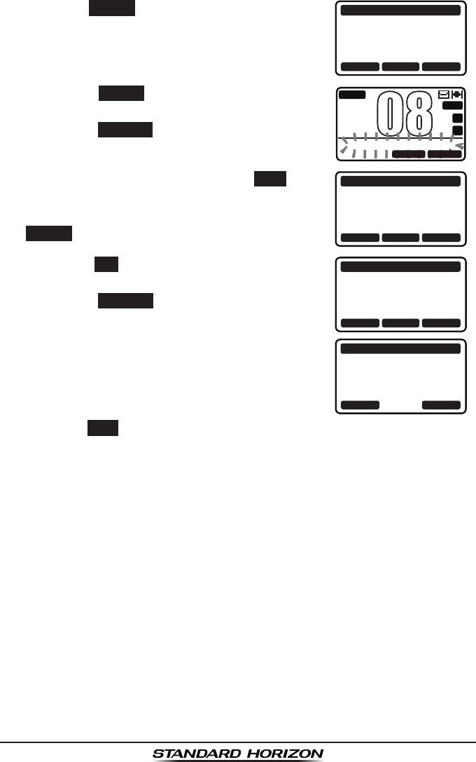
Page 53GX1300
3. Press the ACCEPT soft key to accept the call. RX INDIVIDUAL
YAESU
CATEG: ROUTINE
CH: 08
SINCE: 00:05
ACCEPT QUITPAUSE
4. Press the PAUSE
soft key to suspend the
acknowledgement.
Press the RESUME
soft key to resume the
acknowledgement.
BUSY
MEM
A
C
USA
25W
INDIVIDUAL PAUSE
08
QUITRESUME
5. After accepting the call, press the ABLE soft
key to switch to the requested channel. (To
inform that you cannot respond, press the
UNABLE soft key.)
RX INDIVIDUAL
YAESU
CATEG: ROUTINE
CH: 08
SINCE: 00:08
ABLE QUITUNABLE
6. Press the YES soft key to send an acknowl-
edgement.
Press the CHG CH
soft key to change the
channel for communication from the requested
one.
RX INDIVIDUAL
YAESU
CH: 08
ABLE TO COMPLY
Transmit a Call?
YE
SN
OCNG CH
RX INDIVIDUAL
YAESU
CH: 08
SINCE: 00:05
[ Conncted ]
RESEND QUIT
7. After sending the acknowledgement, the
GX1300 switches to the requested channel
or to the channel selected in step 6, without
changing the display. To change the display,
press the QUIT soft key.
8. Monitor the channel to make sure it is clear, then press the PTT switch
on the microphone and talk to the calling vessel.
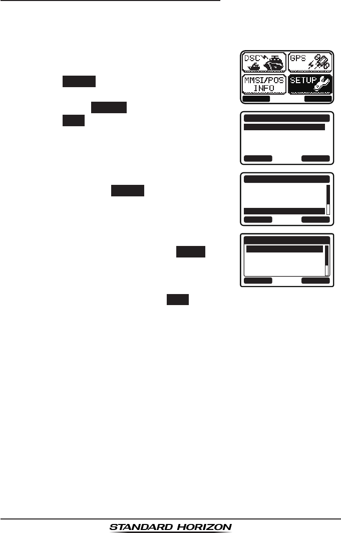
GX1300Page 54
9.5.6 Setting up the Individual Call Ringer
When an individual call is received the radio will produce a ringing tone for 3
minutes (by default). This selection allows the individual call ringer time to be
changed.
1. Press the MENU key to display the menu.
BACK SELECT
BACK SELECT
SETUP
DSC SETUPGROUP
CHANNEL SETUP
CONFIGURATION
2. Press the ▲ / ▼ keys to select “SETUP”, then
press the SELECT soft key.
3. Press the ▲ / ▼ keys to select “DSC SETUP”,
then press the SELECT soft key. (To cancel,
press the BACK soft key.)
4. Select “INDIVIDUAL RING” with the ▲ / ▼
keys, then press the SELECT soft key.
BACK SELECT
DSC SETUP
INDIVIDUAL DIR.
INDIVIDUAL REPLY
INDIVIDUAL ACK
INDIVIDUAL RING
5. Press the ▲ / ▼ keys to select ringing time of
an individual call, then press the ENTER soft
key.
BACK ENTER
INDIVIDUAL RING
2 min
5 sec
10 sec
15 sec
6. Press the 16/S key or press the BACK soft key to return to radio opera-
tion mode.
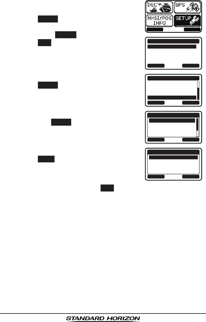
Page 55GX1300
The GX1300 has the capability to turn off the individual call ringer.
1. Press the MENU key to display the menu.
BACK SELECT
BACK SELECT
SETUP
DSC SETUPGROUP
CHANNEL SETUP
CONFIGURATION
2. Press the ▲ / ▼ keys to select “SETUP”, then
press the SELECT soft key.
3. Press the ▲ / ▼ keys to select “DSC SETUP”,
then press the SELECT soft key. (To cancel,
press the BACK soft key.)
4. Select “DSC BEEP” with the ▲ / ▼ keys, then
press the SELECT soft key.
BACK SELECT
DSC SETUP
AUTO POS POLL
AUTO POS TIME
CH SWITCH TIMER
DSC BEEP
5. Select “INDIVIDUAL” with the ▲ / ▼ keys,
then press the SELECT soft key.
BACK SELECT
DSC BEEP
INDIVIDUAL
GROUP
ALL SHIPS
POS REQUEST
ON
ON
ON
OFF
6. Press the ▲ / ▼ keys to select “OFF”, then
press the ENTER soft key.
BACK ENTER
INDIVIDUAL
OFF
ON
7. Press the 16/S key or press the BACK soft key to return to radio opera-
tion mode.
If you wish to return to enabling the ringer tone, just repeat the above proce-
dure, pressing the ▲ / ▼ keys to select “ON” in step 6 above.

GX1300Page 56
9.6 GROUP CALL
This feature allows the user to contact a group of specic vessels (example
members of a yacht club) with a group MMSI number using the group call
function to automatically switch to a desired channel for voice communi-
cations. This function is very useful for yacht clubs and vessels traveling
together that want to collectively make announcements on a predetermined
channel. The GX1300 can store up to 20 group call entries.
9.6.1 Setting up a Group Call
For this function to operate the same group MMSI must be programmed into
all the DSC VHF radios within the group of vessels that will be using this
feature. To understand about group MMSI programming, rst a Ship MMSI
has to be understood.
Ship MMSI: The first three digits called a MID (Mobile Identity Group) of
a ship MMSI denote the country the ship registered for a MMSI. The last
6 digits are specic to the ships ID. Ship MMSI Example: If your MMSI is
“366123456”, “366” is MID which denote the country and “123456” is the
ships ID for you.
Group MMSI:
Group MMSI numbers are not assigned by the FCC or other organiza-
tions licensed to assign ship MMSI numbers.
The rst digit of a group MMSI is always set to “0” by the international
rules. All Standard Horizon radios are preset so when programming a
group MMSI the rst digit is set to “0”.
The USCG recommends programming the MID of a ships MMSI into the
second, third and fourth digits of the group MMSI as it denotes the area
the ship is located in.
The last 5 digits are decided upon by persons in the group. This is an
important step as all radios in the group must contain the same group
MMSI so they can be contacted by each other. There is a chance that
another group of vessels may program in the same group MMSI. If this
happens, simply change one or more of the last 5 digits of the group
MMSI.
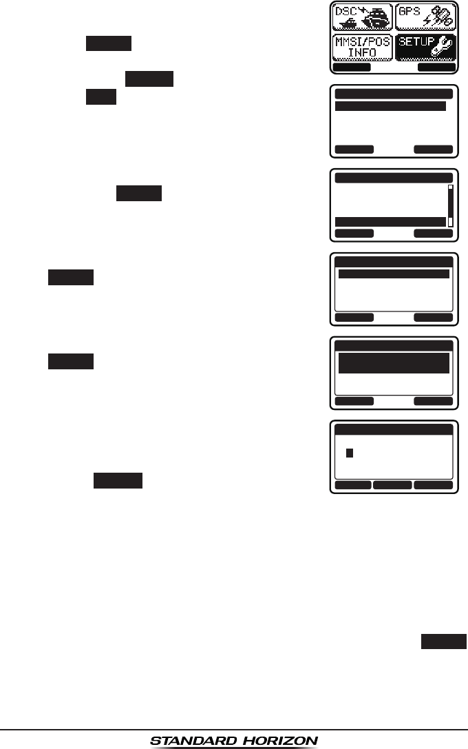
Page 57GX1300
1. Press the MENU key to display the menu.
BACK SELECT
BACK SELECT
SETUP
DSC SETUPGROUP
CHANNEL SETUP
CONFIGURATION
2. Press the ▲ / ▼ keys to select “SETUP”, then
press the SELECT soft key.
3. Press the ▲ / ▼ keys to select “DSC SETUP”,
then press the SELECT soft key. (To cancel,
press the BACK soft key.)
4. Select “GROUP DIR.” with the ▲ / ▼ keys,
then press the SELECT soft key.
BACK SELECT
DSC SETUP
INDIVIDUAL REPLY
INDIVIDUAL ACK
INDIVIDUAL RING
GROUP DIR.
5. Select “ADD” with the ▲ / ▼ keys, then press
the SELECT soft key.
BACK SELECT
GROUP DIR.
ADD
EDIT
DELETE
6. Select “NAME” with the ▲ / ▼ keys, then press
the SELECT soft key.
BACK SELECT
ADD
NAME:
-------------
GROUP MMSI:
0--------
7. Press the ▲ / ▼ keys to scroll through the rst
letter of the group name you want to reference
in the directory.
BACK SELECTFINISH
ADD
NAME:
Y--------------
8. Press the SELECT soft key to store the first
letter in the name and step to the next letter to
the right.
9. Repeat steps 7 and 8 until the name is complete.
Press the ► key to move to the next space if you want to enter a blank
space in the name.
If a mistake was made entering in the name, press the ◄ / ► keys
repeatedly until the wrong letter is highlighted, then press the ▲ / ▼
keys to correct the entry.
10. After the eleventh letter or space has been entered, press the FINISH
soft key to return to the previous screen.
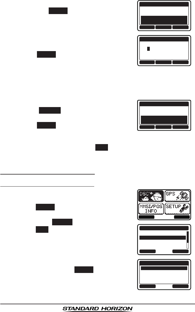
GX1300Page 58
11. Select “GROUP MMSI” with the ▲ / ▼ keys,
then press the SELECT soft key.
ADD
NAME:
YAESU-GP----
GROUP MMSI:
0--------
BACK SELECTFINISH
12. Press the ▲ / ▼ keys to scroll through
numbers, 0 to 9.
BACK SELECTFINISH
ADD
GROUP MMSI:
03---------
13. Press the SELECT soft key to store the number
and step to the next digit to the right.
14. Repeat steps 12 and 13 until the group MMSI is complete.
If a mistake was made entering in the MMSI number, press the ◄ / ►
keys repeatedly until the wrong number is highlighted, then press the ▲
/ ▼ keys to correct the entry.
15. After the nineth number has been entered,
press the FINISH soft key to return to the
previous screen.
ADD
NAME:
YAESU-GP----
GROUP MMSI:
036690155
BACK SELECTFINISH
16. Press the FINISH soft key to save the entered
data.
17. To enter another group entry, repeat steps 5 through 16.
18. Press the 16/S key or press the BACK soft key to return to radio opera-
tion mode.
9.6.2 Transmitting a Group Call
Group Call from Group Call Directory
1. Press the MENU key to display the menu.
BACK SELECT
BACK SELECT
DSC CALL
INDIVIDUAL
GROUP
ALL SHIPS
DIST ALERT MSG
2. Press the ▲ / ▼ keys to select “DSC”, then
press the SELECT soft key.
3. Press the ▲ / ▼ keys to select “GROUP”, and
then press the SELECT soft key. (To cancel,
press the BACK soft key.)
4. Press the ▲ / ▼ keys to select “HISTORY” or
“MEMORY”, then press the SELECT soft key.
BACK SELECT
GROUP
HISTORY
MEMORY
NEW ID
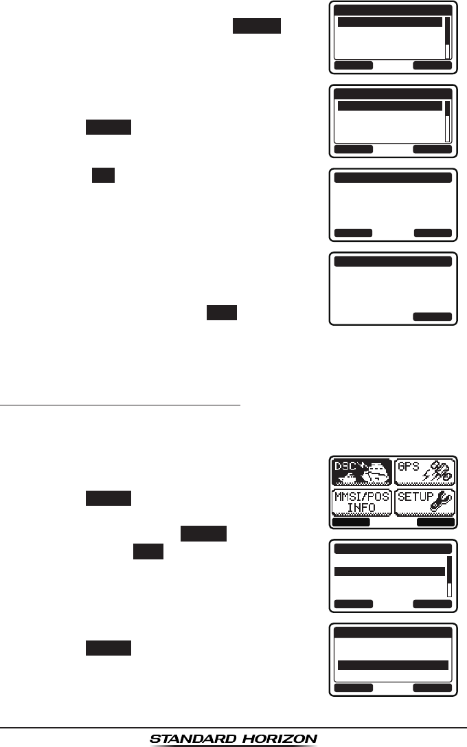
Page 59GX1300
5. Press the ▲ / ▼ keys to select a group you
want to contact, then press the SELECT soft
key.
BACK SELECT
HISTORY
YAESU GP
USCG GP
MEMORY SHIPS
HORIZON GP
6. Press the ▲ / ▼ keys to select the operat-
ing channel you want to communicate on and
press the SELECT soft key.
BACK SELECT
INTERSHIP CH
CH:06
CH:08
CH:09
CH:10
7. Press the YES soft key to transmit the group
call signal.
GROUP
YAESU GP
CATEG: ROUTINE
CH: 08
Transmit a Call?
YE
SN
O
8. After the group call is transmitted, the trans-
ceiver will switch to the channel selected in
step 6 above, without changing the display. To
change the display, press the QUIT soft key.
GROUP
YAESU GP
CH: 08
SINCE: 00:05
[ Transmitted ]
QUIT
9. Listen to the channel to make sure it is not busy, then key the micro-
phone and call the other vessels you desire to communicate with.
Group Call - Manual Group MMSI Entry
You may enter an MMSI number manually to contact a vessel without storing
the MMSI in the Group Call Directory.
1. Press the MENU key to display the menu.
BACK SELECT
BACK SELECT
DSC CALL
INDIVIDUAL
GROUP
ALL SHIPS
DIST ALERT MSG
2. Press the ▲ / ▼ keys to select “DSC”, then
press the SELECT soft key.
3. Press the ▲ / ▼ keys to select “INDIVIDU-
AL”, and then press the SELECT soft key. (To
cancel, press the BACK soft key.)
4. Press the ▲ / ▼ keys to select “NEW ID”, then
press the SELECT soft key.
BACK SELECT
GROUP
HISTORY
MEMORY
NEW ID
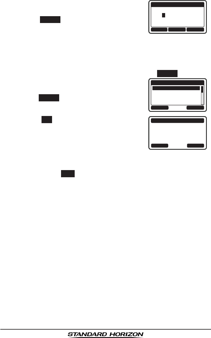
GX1300Page 60
5. Press the ▲ / ▼ keys to scroll through
numbers, 0 to 9.
BACK SELECTFINISH
NEW ID
GROUP MMSI:
03---------
6. Press the SELECT soft key to store the number
and step to the next digit to the right.
7. Repeat steps 5 and 6 until the MMSI is complete.
If a mistake was made entering in the MMSI number, press the ◄ / ►
keys repeatedly until the wrong number is highlighted, then press the ▲
/ ▼ keys to correct the entry.
8. After the nineth number has been entered, press the FINISH soft key.
9. Press the ▲ / ▼ keys to select the operat-
ing channel you want to communicate on and
press the SELECT soft key.
BACK SELECT
INTERSHIP CH
CH:06
CH:08
CH:09
CH:10
10. Press the YES soft key to transmit the group
call signal.
GROUP
036690155
CATEG: ROUTINE
CH: 08
Transmit a Call?
YE
SN
O
11. After the group call is transmitted, the transceiver will switch to the
channel selected in step 9, without changing the display. To change the
display, press the QUIT soft key.
12. Listen to the channel to make sure it is not busy, then key the micro-
phone and call the other vessels you desire to communicate with.
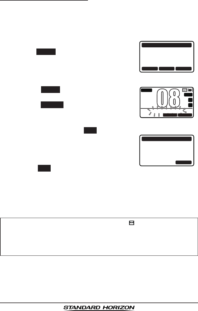
Page 61GX1300
9.6.3 Receiving a Group Call
1. When a group call is received, the GX1300 will produce a ringing alarm
sound. (DSC BEEP needs to be enabled to hear alarm.)
The display will show the MMSI (or name) of the vessel transmitting the
group call.
2. Press any key to stop the alarm.
3. To immediately switch to requested channel,
press the ACCEPT soft key.
If a key is not pressed for thirty seconds after
a group call is received, the GX1300 will
automatically switch to the requested channel
for you to monitor communications.
RX GROUP
YAESU
CATEG: ROUTINE
CH: 08
SINCE: 00:05
ACCEPT QUITPAUSE
4. Press the PAUSE
soft key to suspend the
acknowledgement.
Press the RESUME
soft key to resume the
acknowledgement.
BUSY
MEM
A
C
USA
25W
GROUP PAUSE
08
QUITRESUME
5. If you want the radio to stay on the channel you were on before receiv-
ing the group call, press the QUIT soft key.
6. Press the ▲ / ▼ keys to scroll the screen and
see the MMSI (or name) of the calling vessel,
category of the call and requested operating
channel.
RX GROUP
YAESU
CATEG: ROUTINE
CH: 08
SINCE: 00:08
ABLE QUITUNABLE
7. Press the QUIT soft key to display the operat-
ing channel number of the requested channel.
8. Listen to the channel for the person calling the group for a message.
9. If you want to respond, monitor the channel to make sure it is clear, then
press the PTT switch on the microphone and talk to the calling ship(s).
NOTE
When there is an unread group call, the “ ” icon will appear on
the display. You may review the unread group call from the DSC
log, refer to section “9.12.3 Reviewing a Logged Other Calls.”
After a group call is received, the time the call was made and the
ships MMSI or vessels name will appear on the LCD.
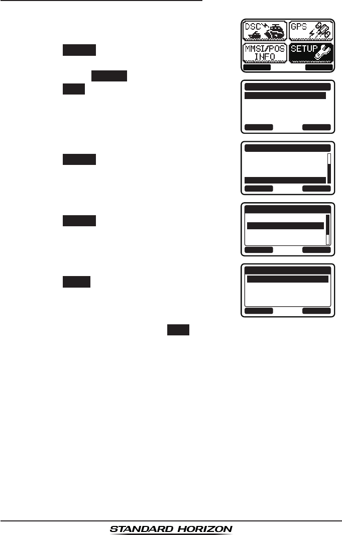
GX1300Page 62
9.6.4 Setting up the Group Call Ringer
The GX1300 has the capability to turn off the group call ringer.
1. Press the MENU key to display the menu.
BACK SELECT
BACK SELECT
SETUP
DSC SETUPGROUP
CHANNEL SETUP
CONFIGURATION
2. Press the ▲ / ▼ keys to select “SETUP”, then
press the SELECT soft key.
3. Press the ▲ / ▼ keys to select “DSC SETUP”,
then press the SELECT soft key. (To cancel,
press the BACK soft key.)
4. Select “DSC BEEP” with the ▲ / ▼ keys, then
press the SELECT soft key.
BACK SELECT
DSC SETUP
AUTO POS POLL
AUTO POS TIME
CH SWITCH TIMER
DSC BEEP
5. Select “GROUP” with the ▲ / ▼ keys, then
press the SELECT soft key.
BACK SELECT
DSC BEEP
INDIVIDUAL
GROUP
ALL SHIPS
POS REQUEST
ON
ON
ON
OFF
6. Press the ▲ / ▼ keys to select “OFF”, then
press the ENTER soft key.
BACK ENTER
GROUP
OFF
ON
7. Press the 16/S key or press the BACK soft key to return to radio opera-
tion mode.
If you wish to return to enabling the ringer tone, just repeat the above proce-
dure, pressing the ▲ / ▼ keys to select “ON” in step 6 above.
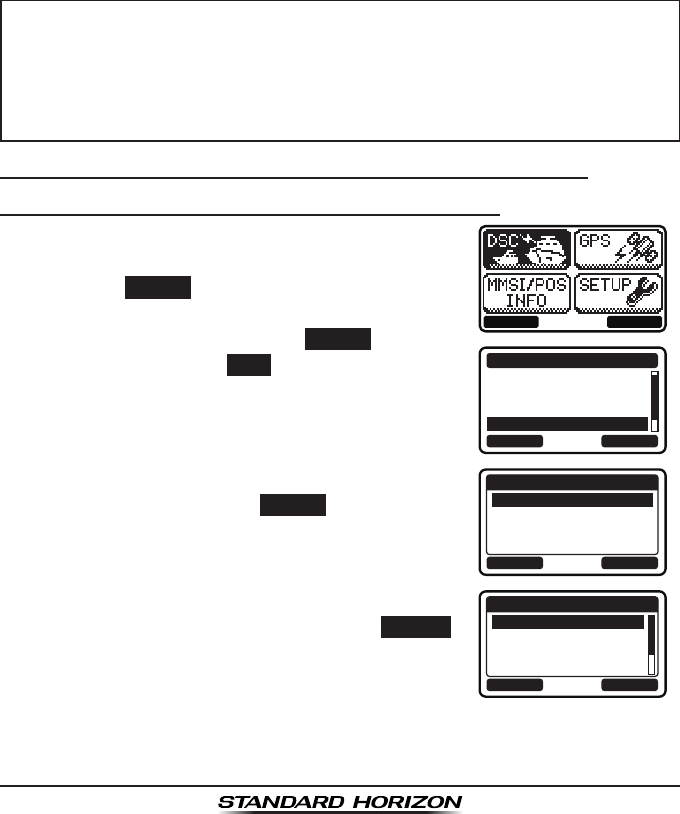
Page 63GX1300
9.7 POSITION REQUEST
Advancements in DSC have made it possible to poll the location of another
vessel and show the position of that vessel on the display of the GX1300.
Standard Horizon has taken this feature one step further, if any Standard
Horizon GPS is connected to the GX1300, the polled position of the vessel is
shown on the display of the GPS chart plotter making it easy to navigate to
the location of the polled vessel. This is a great feature for anyone wanting to
know the position of another vessel. For example your friend that is catching
sh, or nding the location of a person you are cruising with.
NOTE
9.7.1 Transmitting a Position Request to Another Vessel
Position Request from Individual / Position Call Directory
1. Press the MENU key to display the menu.
BACK SELECT
BACK SELECT
DSC CALL
GROUP
ALL SHIPS
DIST ALERT MSG
POS REQUEST
2. Press the ▲ / ▼ keys to select “DSC”, then
press the SELECT soft key.
3. Press the ▲ / ▼ keys to select “POS
REQUEST”, and then press the SELECT soft key.
(To cancel, press the BACK soft key.)
4. Press the ▲ / ▼ keys to select “HISTORY” or
“MEMORY”, then press the SELECT soft key.
BACK SELECT
POS REQUEST
HISTORY
MEMORY
NEW ID
5. Press the ▲ / ▼ keys to select an individual
you want to contact, then press the SELECT
soft key.
BACK SELECT
MEMORY
YAESU
USCG
MEMORY SHIPS
HORIZON
The other vessel must have an operating GPS receiver connected to
its DSC transceiver and must not have its transceiver set to deny po-
sition requests. (Refer the section “9.5.1 Setting up the Individual /
Position Call Directory” to enter information into the individual direc-
tory).
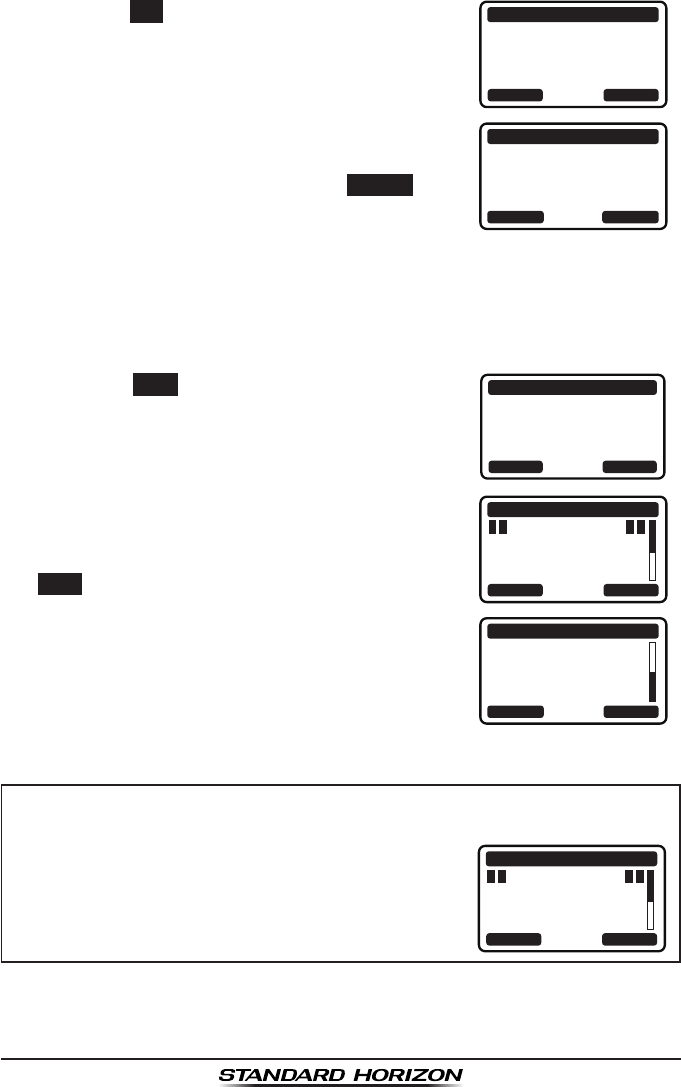
GX1300Page 64
6. Press the YES soft key to transmit the position
request call.
POS REQUEST
YAESU
CATEG: SAFETY
Transmit a Call?
YE
SN
O
7. If the GX1300 does not receive a reply, the
display will be as shown in the illustration on
the right. To send again, press the RESEND soft
key.
POS REQUEST
YAESU
CATEG: SAFETY
SINCE: 00:05
[Waiting for ACK]
RESEND QUIT
8. When the GX1300 receives the position from the polled vessel, the
GX1300 will produce a ringing alarm sound and the position from the
polled vessel is sent to a GPS chart plotter via NMEA 0183. (DSC BEEP
needs to be enabled to hear alarm.)
Press any key to stop the alarm.
9. Press the INFO soft key to show the position
data transferred from the polled vessel on the
display.
RX POS REPLY
YAESU
POS ACKNOWLEDGED
SINCE: 00:05
QUITINFO
10. Press the ▲ / ▼ keys to change the display to
view the received data. POS INFO
POS: 23°56.890N
123°56.890W
TIME: 12:56 UTC
RX POS REPLY
BACK QUIT
BACK
RX POS REPLY
QUIT
123°56.890W
TIME: 12:56 UTC
DST: 29.8NM
BRG: 270°T
11. To exit from position request display, press the
QUIT soft key.s
NOTE
If the GX1300 does not receive position data from the polled vessel,
the LCD will show “NO POSITION DATA”.
POS INFO
POS: --°--.---_
---°--.---_
TIME: --:--
RX POS REPLY
BACK QUIT
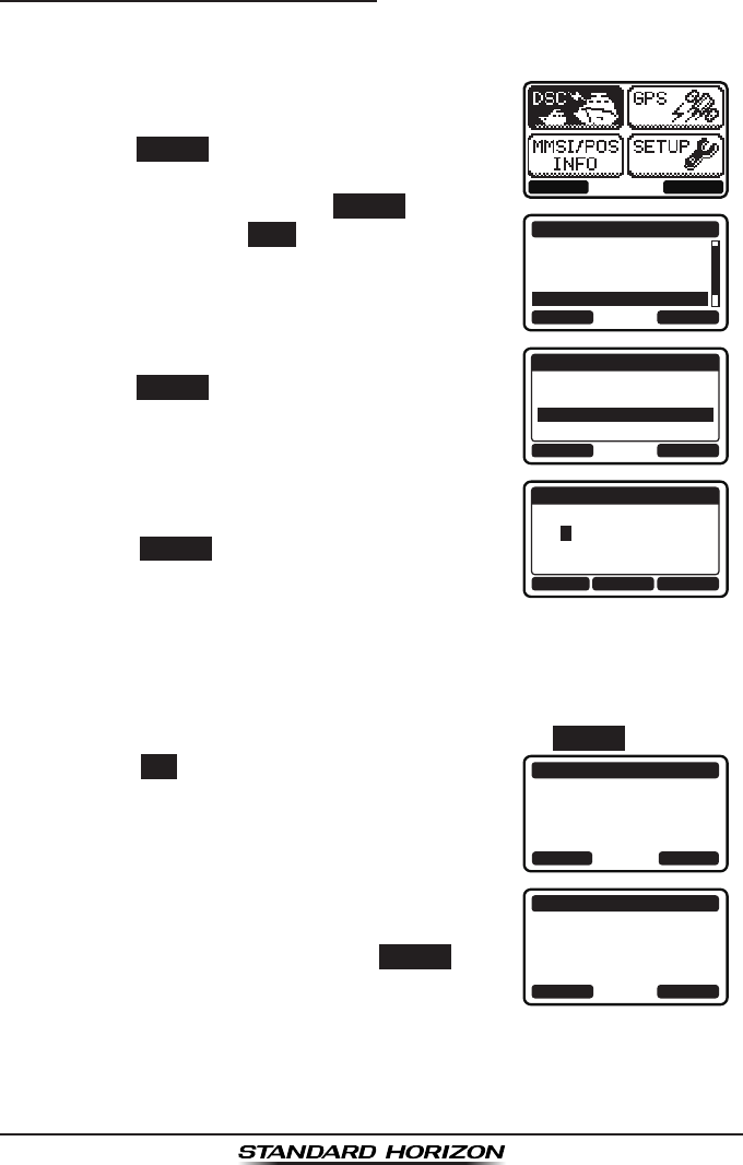
Page 65GX1300
Position Request - Manual MMSI Entry
You may enter an MMSI number manually to contact a vessel without storing
the MMSI in the individual/position call directory.
1. Press the MENU key to display the menu.
BACK SELECT
BACK SELECT
DSC CALL
GROUP
ALL SHIPS
DIST ALERT MSG
POS REQUEST
2. Press the ▲ / ▼ keys to select “DSC”, then
press the SELECT soft key.
3. Press the ▲ / ▼ keys to select “POS
REQUEST”, and then press the SELECT soft key.
(To cancel, press the BACK soft key.)
4. Press the ▲ / ▼ keys to select “NEW ID”, then
press the SELECT soft key.
BACK SELECT
POS REQUEST
HISTORY
MEMORY
NEW ID
5. Press the ▲ / ▼ keys to scroll through
numbers, 0 to 9.
BACK SELECTFINISH
NEW ID
MMSI:
3----------
6. Press the SELECT soft key to store the number
and step to the next digit to the right.
7. Repeat steps 5 and 6 until the MMSI is complete.
If a mistake was made entering in the MMSI number, press the ◄ / ►
keys repeatedly until the wrong number is highlighted, then press the ▲
/ ▼ keys to correct the entry.
8. After the nineth number has been entered, press the FINISH soft key.
9. Press the YES soft key to transmit the position
request call.
POS REQUEST
366901555
CATEG: SAFETY
Transmit a Call?
YE
SN
O
10. If the GX1300 does not receive a reply, the
display will be as shown in the illustration on
the right. To send again, press the RESEND soft
key.
POS REQUEST
366901555
CATEG: SAFETY
SINCE: 00:05
[Waiting for ACK]
RESEND QUIT
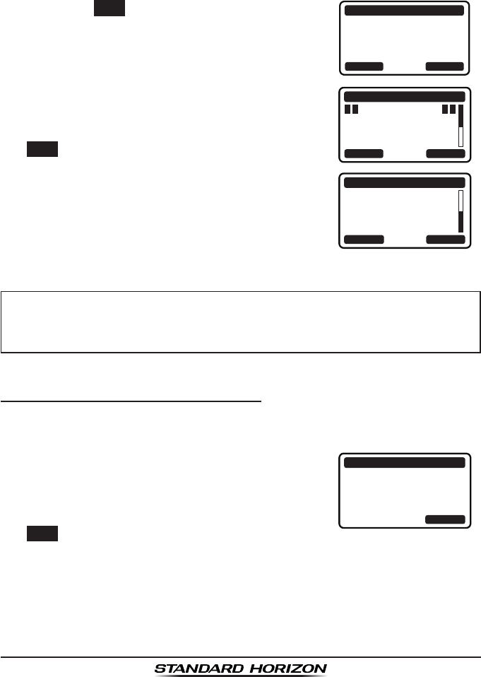
GX1300Page 66
11. When the GX1300 receives the position from the polled vessel, the
GX1300 will produce a ringing alarm sound and the position from the
polled vessel is sent to a GPS chart plotter via NMEA 0183. (DSC BEEP
needs to be enabled to hear alarm.)
Press any key to stop the alarm.
12. Press the INFO soft key to show the position
data transferred from the polled vessel on the
display.
RX POS REPLY
366901555
POS ACKNOWLEDGED
SINCE: 00:05
QUITINFO
13. Press the ▲ / ▼ keys to change the display to
view the received data. POS INFO
POS: 23°56.890N
123°56.890W
TIME: 12:56 UTC
RX POS REPLY
BACK QUIT
BACK
RX POS REPLY
QUIT
123°56.890W
TIME: 12:56 UTC
DST: 29.8NM
BRG: 270°T
14. To exit from position request display, press the
QUIT soft key.
NOTE
9.7.2 Receiving a Position Request
When a position request call is received from another vessel, a ringing alarm
will sound and "POS REQUEST" will be shown in the LCD.
1. When a position request call is received,
the GX1300 will transmit your position to the
vessel who requested it.
RX POS REQUEST
YAESU
POS REPLY
SINCE: 00:05
[ Transmitted ]
QUIT
2. To exit from position request display, press the
QUIT soft key.
If the GX1300 does not receive position data from the polled vessel,
the LCD will show “NO POSITION DATA”.
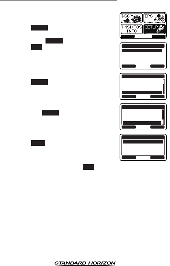
Page 67GX1300
9.7.3 Setting up the Position Request Ringer
The GX1300 has the capability to turn off the position request ringer.
1. Press the MENU key to display the menu.
BACK SELECT
BACK SELECT
SETUP
DSC SETUPGROUP
CHANNEL SETUP
CONFIGURATION
2. Press the ▲ / ▼ keys to select “SETUP”, then
press the SELECT soft key.
3. Press the ▲ / ▼ keys to select “DSC SETUP”,
then press the SELECT soft key. (To cancel,
press the BACK soft key.)
4. Select “DSC BEEP” with the ▲ / ▼ keys, then
press the SELECT soft key.
BACK SELECT
DSC SETUP
AUTO POS POLL
AUTO POS TIME
CH SWITCH TIMER
DSC BEEP
5. Select “POS REQUEST” with the ▲ / ▼ keys,
then press the SELECT soft key.
BACK SELECT
DSC BEEP
INDIVIDUAL
GROUP
ALL SHIPS
POS REQUEST
ON
ON
ON
OFF
6. Press the ▲ / ▼ keys to select “OFF”, then
press the ENTER soft key.
BACK ENTER
POS REQUEST
OFF
ON
7. Press the 16/S key or press the BACK soft key to return to radio opera-
tion mode.
If you wish to return to enabling the ringer tone, just repeat the above proce-
dure, pressing the ▲ / ▼ keys to select “ON” in step 6 above.
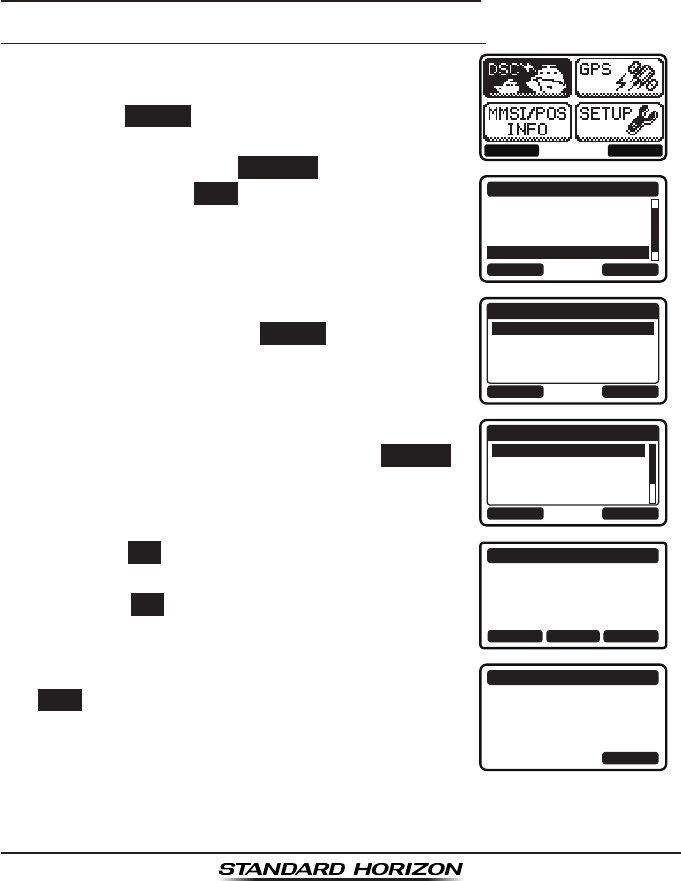
GX1300Page 68
9.8 POSITION REPORT
The feature is similar to the position request, however instead of requesting
a position of another vessel this function allows you to send your position
to another vessel. In order to send your position you need to have a GPS
receiver connected or to have manually input your position. See section “9.9
MANUAL INPUTTING OF THE GPS LOCATION.”
9.8.1 Transmitting a DSC Position Report Call
Position Report from Individual / Position Call Directory
1. Press the MENU key to display the menu.
BACK SELECT
BACK SELECT
DSC CALL
ALL SHIPS
DIST ALERT MSG
POS REQUEST
POS REPORT
2. Press the ▲ / ▼ keys to select “DSC”, then
press the SELECT soft key.
3. Press the ▲ / ▼ keys to select “POS REPORT”,
and then press the SELECT
soft key. (To
cancel, press the BACK soft key.)
4. Press the ▲ / ▼ keys to select “HISTORY” or
“MEMORY”, then press the SELECT soft key.
BACK SELECT
POS REPORT
HISTORY
MEMORY
NEW ID
5. Press the ▲ / ▼ keys to select an individual
you want to contact, then press the SELECT
soft key.
BACK SELECT
MEMORY
YAESU
USCG
MEMORY SHIPS
HORIZON
6. Press the YES soft key to send your position to
the selected vessel.
Press the POS soft key to change the position
information.
POS REPORT
YAESU
POS:
23°56.890N
123°56.890W
Transmit a Call?
YE
SN
OPOS/TM
7. To exit from position request display, press the
QUIT soft key.
POS REPORT
YAESU
CATEG: SAFETY
SINCE: 00:05
[ Transmitted ]
QUIT
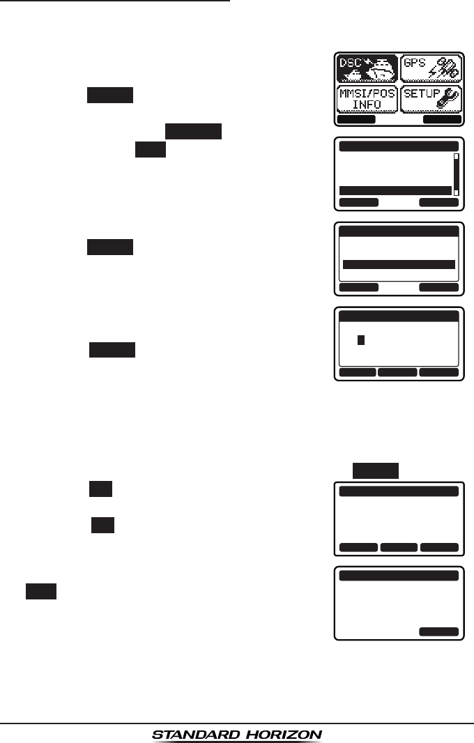
Page 69GX1300
Position Report - Manual MMSI Entry
You may enter an MMSI number manually to contact a vessel without storing
the MMSI in the individual/position call directory.
1. Press the MENU key to display the menu.
BACK SELECT
BACK SELECT
DSC CALL
ALL SHIPS
DIST ALERT MSG
POS REQUEST
POS REPORT
2. Press the ▲ / ▼ keys to select “DSC”, then
press the SELECT soft key.
3. Press the ▲ / ▼ keys to select “POS REPORT”,
and then press the SELECT
soft key. (To
cancel, press the BACK soft key.)
4. Press the ▲ / ▼ keys to select “NEW ID”, then
press the SELECT soft key.
BACK SELECT
POS REPORT
HISTORY
MEMORY
NEW ID
5. Press the ▲ / ▼ keys to scroll through
numbers, 0 to 9.
BACK SELECTFINISH
NEW ID
MMSI:
3----------
6. Press the SELECT soft key to store the number
and step to the next digit to the right.
7. Repeat steps 5 and 6 until the MMSI is complete.
If a mistake was made entering in the MMSI number, press the ◄ / ►
keys repeatedly until the wrong number is highlighted, then press the ▲
/ ▼ keys to correct the entry.
8. After the nineth number has been entered, press the FINISH soft key.
9. Press the YES soft key to send your position to
the selected vessel.
Press the POS soft key to change the position
information.
POS REPORT
366901555
POS:
23°56.890N
123°56.890W
Transmit a Call?
YE
SN
OPOS/TM
10. To exit from position request display, press the
QUIT soft key.
POS REPORT
366901555
CATEG: SAFETY
SINCE: 00:05
[ Transmitted ]
QUIT
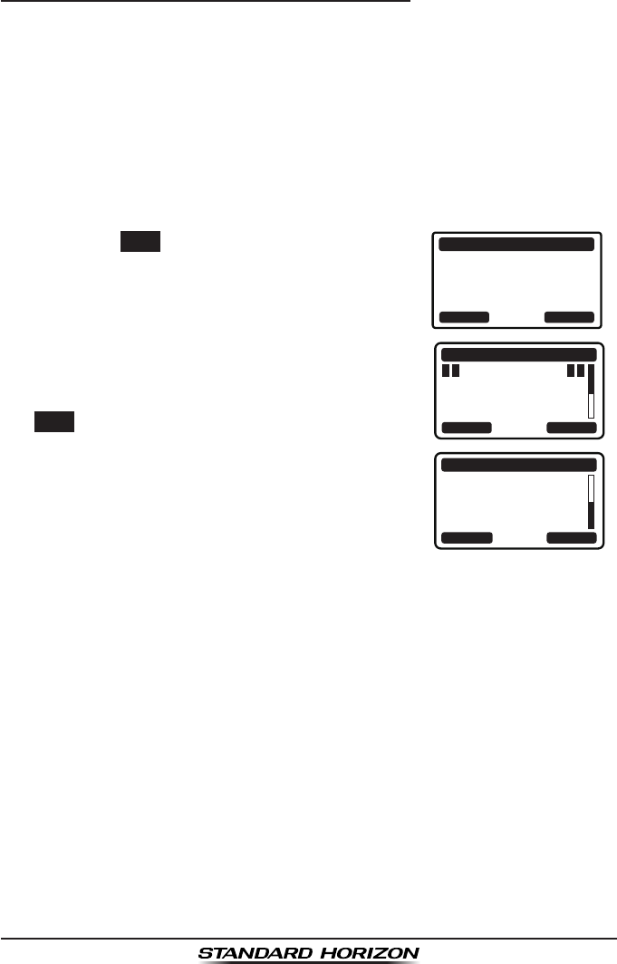
GX1300Page 70
9.8.2 Receiving a DSC Position Report Call
When another vessel transmits their location to the GX1300 the following will
happen:
1. When the position report call is received, a ringing sound will be
produced and the display shows the vessels MMSI or name, how long
since the call was received and the GPS position of the vessel. The
GX1300 will also output NMEA sentences (DSC and DSE) to a connect-
ed GPS chart plotter.
2. Press any key on the radio to stop the alarm. (DSC BEEP needs to be
enabled to hear alarm.)
3. Press the INFO soft key to show the position
data transferred from the calling vessel.
RX POS REPORT
YAESU
POS: 23°56.890N
123°56.890W
SINCE: 00:05
QUITINFO
4. Press the ▲ / ▼ keys to change the display to
view the received data. POS INFO
POS: 23°56.890N
123°56.890W
TIME: 12:56 UTC
RX POS REPORT
BACK QUIT
BACK
RX POS REPORT
QUIT
123°56.890W
TIME: 12:56 UTC
DST: 29.8 NM
BRG: 270°T
5. To exit from position request display, press the
QUIT soft key.

Page 71GX1300
9.8.5 Setting up a Position Report Ringer
The GX1300 has the capability to turn off the position report ringer.
1. Press the MENU key to display the menu.
BACK SELECT
BACK SELECT
SETUP
DSC SETUPGROUP
CHANNEL SETUP
CONFIGURATION
2. Press the ▲ / ▼ keys to select “SETUP”, then
press the SELECT soft key.
3. Press the ▲ / ▼ keys to select “DSC SETUP”,
then press the SELECT soft key. (To cancel,
press the BACK soft key.)
4. Select “DSC BEEP” with the ▲ / ▼ keys, then
press the SELECT soft key.
BACK SELECT
DSC SETUP
AUTO POS POLL
AUTO POS TIME
CH SWITCH TIMER
DSC BEEP
5. Select “POS REPORT” with the ▲ / ▼ keys,
then press the SELECT soft key.
BACK SELECT
DSC BEEP
GROUP
ALL SHIPS
POS REQUEST
POS REPORT
ON
ON
OFF
OFF
6. Press the ▲ / ▼ keys to select “OFF”, then
press the ENTER soft key.
BACK ENTER
POS REPORT
OFF
ON
7. Press the 16/S key or press the BACK soft key to return to radio opera-
tion mode.
To enable the position report ringer, repeat the above procedure, pressing
the ▲ / ▼ keys to select “ON” in step 7 above.
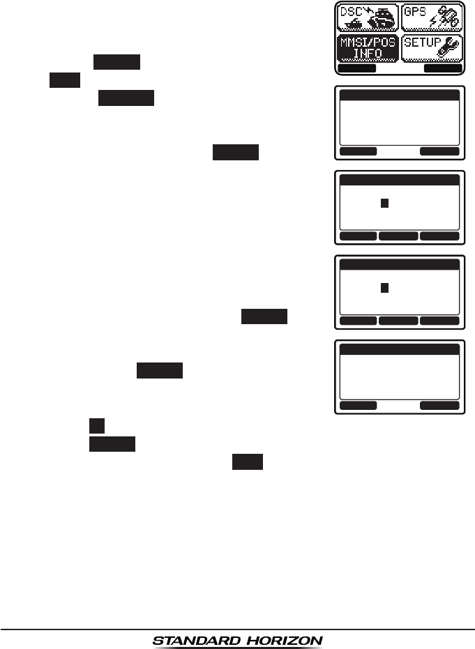
GX1300Page 72
9.9 MANUAL INPUTTING OF THE GPS LOCATION (LAT/LON)
You may send the latitude and longitude of your vessel manually when a
GPS receiver is not connected or is not functioning.
After the position is entered, transmitting a DSC distress or position report
will contain the manually entered position.
1. Press the MENU key to display the menu.
BACK SELECT
OK POS/TM
MMSI/POS INFO
ID: 366901234
POS: --°--.----
---°--.----
TIME: --:--UTC
BACK SELECT
MMSI/POS INPUT
POS: 2-°--.----
---°--.----
TIME: --:--UTC
FINISH
BACK SELECT
MMSI/POS INPUT
POS: 23°56.890N
123°56.890W
TIME: 12:56UTC
FINISH
OK POS/TM
MMSI/POS INFO
ID: 366901234
POS: 23°56.890N
123°56.890W
TIME: 12:56UTC
2. Press the ▲ / ▼ key to select “MMSI/POS
INFO”.
3. Press the SELECT soft key. (To cancel, press
the BACK soft key.)
4. Press the POS/TM
soft key to display the
position input screen.
5. Press the ▲ / ▼ key to select the rst digit of
your latitude, then press the SELECT soft key
to step to the next digit.
6. Repeat step 5 to enter your latitude and longi-
tude.
7. Enter UTC time in the 24-hour format with the
same procedure in step 5.
8. If a mistake was made entering in the position
and time, press the ◄ / ► key until the wrong
letter is highlighted, then press the ▲ / ▼ key
to correct the entry and press the SELECT soft
key.
9. When nished programming the position infor-
mation, press the FINISH soft key.
10. Press the OK soft key to return to the menu screen.
Press the POS/TM soft key to display the position input screen again.
11. Press the 16/S key or press the BACK soft key to return to radio opera-
tion mode.
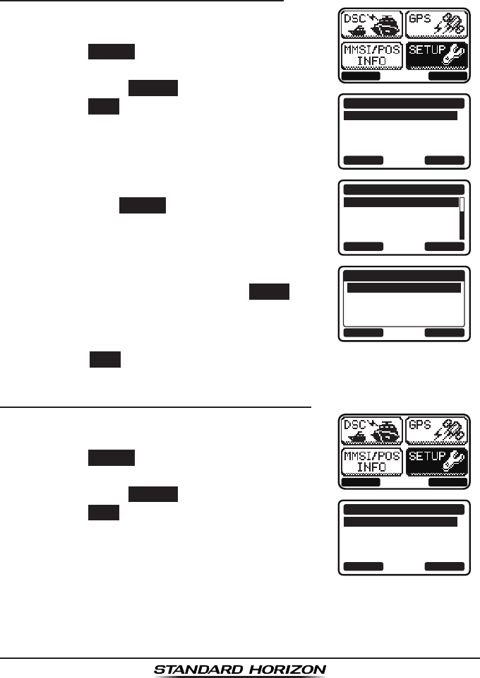
Page 73GX1300
9.10 AUTO POS POLLING
The GX1300 has the capability to automatically track four stations
programmed into the individual directory.
9.10.1 Setting up the Polling Call Type
1. Press the MENU key to display the menu.
BACK SELECT
BACK SELECT
SETUP
DSC SETUPGROUP
CHANNEL SETUP
CONFIGURATION
2. Press the ▲ / ▼ keys to select “SETUP”, then
press the SELECT soft key.
3. Press the ▲ / ▼ keys to select “DSC SETUP”,
then press the SELECT soft key. (To cancel,
press the BACK soft key.)
4. Select “AUTO POS POLL” with the ▲ / ▼ keys,
then press the SELECT soft key.
BACK SELECT
DSC SETUP
AUTO POS POLL
AUTO POS TIME
CH SWITCH TIMER
DSC BEEP
5. Press the ▲ / ▼ keys to select “POS REQUEST”
or “POS REPORT”, then press the ENTER soft
key.
BACK ENTER
AUTO POS POLL
POS REQUEST
POS REPORT
6. Press the BACK soft key to return to “DSC SETUP”.
9.10.2 Setting up the Polling Time Interval
1. Press the MENU key to display the menu.
BACK SELECT
BACK SELECT
SETUP
DSC SETUPGROUP
CHANNEL SETUP
CONFIGURATION
2. Press the ▲ / ▼ keys to select “SETUP”, then
press the SELECT soft key.
3. Press the ▲ / ▼ keys to select “DSC SETUP”,
then press the SELECT soft key. (To cancel,
press the BACK soft key.)
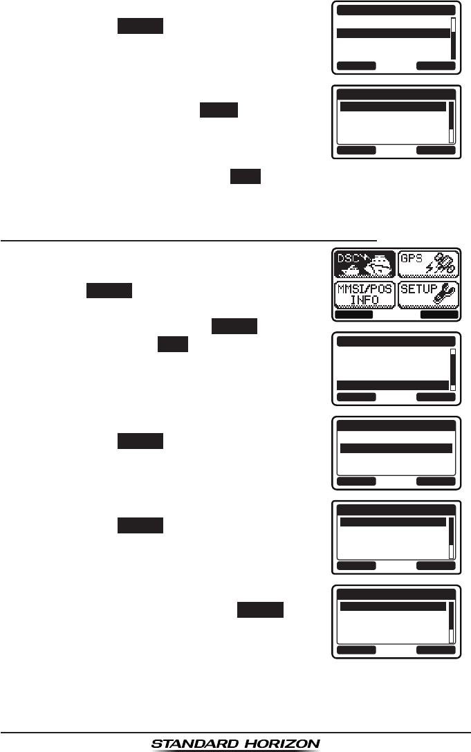
GX1300Page 74
4. Select “AUTO POS TIME” with the ▲ / ▼ keys,
then press the SELECT soft key.
BACK SELECT
DSC SETUP
AUTO POS POLL
AUTO POS TIME
CH SWITCH TIMER
DSC BEEP
5. Press the ▲ / ▼ keys to select the desired
interval time, then press the ENTER soft key.
BACK ENTER
AUTO POS TIME
30 sec
1 min
2 min
3 min
6. Press the 16/S key or press the BACK soft key to return to radio opera-
tion mode.
9.10.3 Selecting Stations to be Automatically Polled
1. Press the MENU key to display the menu.
BACK SELECT
BACK SELECT
DSC CALL
DIST ALERT MSG
POS REQUEST
POS REPORT
AUTO POS POLLING
2. Press the ▲ / ▼ keys to select “DSC”, then
press the SELECT soft key.
3. Press the ▲ / ▼ keys to select “AUTO POS
POLLING”, and then press the SELECT soft key.
(To cancel, press the BACK soft key.)
4. Press the ▲ / ▼ keys to select “SELECT ID”,
then press the SELECT soft key.
BACK SELECT
AUTO POS POLLING
ACTIVATION START
SELECT ID
5. Press the ▲ / ▼ keys to select the list number,
then press the SELECT soft key.
BACK SELECT
SELECT ID
1:
2:
3:
4:
6. Press the ▲ / ▼ keys to select an individual
you want to poll, then press the SELECT soft
key.
BACK SELECT
MEMORY
YAESU
USCG
MEMORY SHIPS
HORIZON
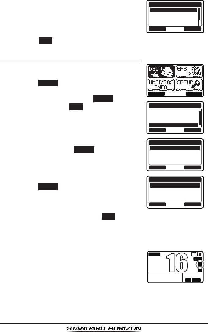
Page 75GX1300
7. Repeat steps 5 and 6 for all the desired
individual to be polled.
BACK SELECT
SELECT ID
1:HORIZON
2:MEMORY SHIPS
3:USCG-2
4:YAESU-1
8. Press the BACK soft key to return to “AUTO POS POLLING”.
9.10.4 Enabling/Disabling Auto POS Polling
1. Press the MENU key to display the menu.
BACK SELECT
BACK SELECT
DSC CALL
DIST ALERT MSG
POS REQUEST
POS REPORT
AUTO POS POLLING
2. Press the ▲ / ▼ keys to select “DSC”, then
press the SELECT soft key.
3. Press the ▲ / ▼ keys to select “AUTO POS
POLLING”, and then press the SELECT soft key.
(To cancel, press the BACK soft key.)
4. Press the ▲ / ▼ keys to select “ACTIVATION
START”, then press the SELECT soft key.
BACK SELECT
AUTO POS POLLING
ACTIVATION START
SELECT ID
5. Press the ▲ / ▼ keys to select “START”, then
press the SELECT soft key.
BACK SELECT
ACTIVATION START
START
STOP
6. Press the 16/S key or press the BACK soft key to return to radio opera-
tion mode.
To disable the auto position polling, repeat the above procedure, pressing
the ▲ / ▼ keys to select “STOP” in step 5 above.
The “A” indicator will appear on the LCD while the
auto position polling is activated.
BUSY
MEM
LOCAM
A
C
USA
25W
123˚56.890W
23˚56.890N 09:56
P
16
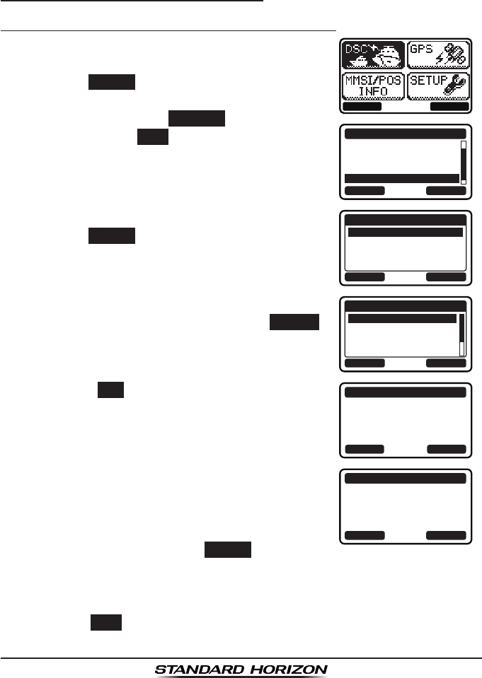
GX1300Page 76
9.11 DSC TEST CALL
Use the following procedure to ensure the DSC feature are functioning with
other DSC radios.
9.11.1 Transmitting a DSC Test Call
DSC Test Call from Individual / Position Call Directory
1. Press the MENU key to display the menu.
BACK SELECT
BACK SELECT
DSC CALL
POS REQUEST
POS REPORT
AUTO POS POLLING
TEST CALL
2. Press the ▲ / ▼ keys to select “DSC”, then
press the SELECT soft key.
3. Press the ▲ / ▼ keys to select “TEST CALL”,
and then press the SELECT
soft key. (To
cancel, press the BACK soft key.)
4. Press the ▲ / ▼ keys to select “MEMORY”, then
press the SELECT soft key.
BACK SELECT
TEST CALL
MEMORY
NEW ID
5. Press the ▲ / ▼ keys to select an individual
you want to contact, then press the SELECT
soft key.
BACK SELECT
MEMORY
YAESU
USCG
MEMORY SHIPS
HORIZON
6. Press the YES soft key to transmit the test
signal.
TEST CALL
YAESU
CATEG: SAFETY
Transmit a Call?
YE
SN
O
7. After the DSC test call is transmitted, the
GX1300 waits for a reply from the radio which
was called, and the display will show “WAITING
FOR ACK”.
To transmit again, press the RESEND soft key.
TEST CALL
YAESU
CATEG: SAFETY
SINCE: 00:05
[Waiting for ACK]
RESEND QUIT
8. When an acknowledgement signal is received, the GX1300 will show “RX
TEST CALL” screen, which conrms the radio you called has received
the test call.
9. Press the QUIT soft key to return to the radio operation.
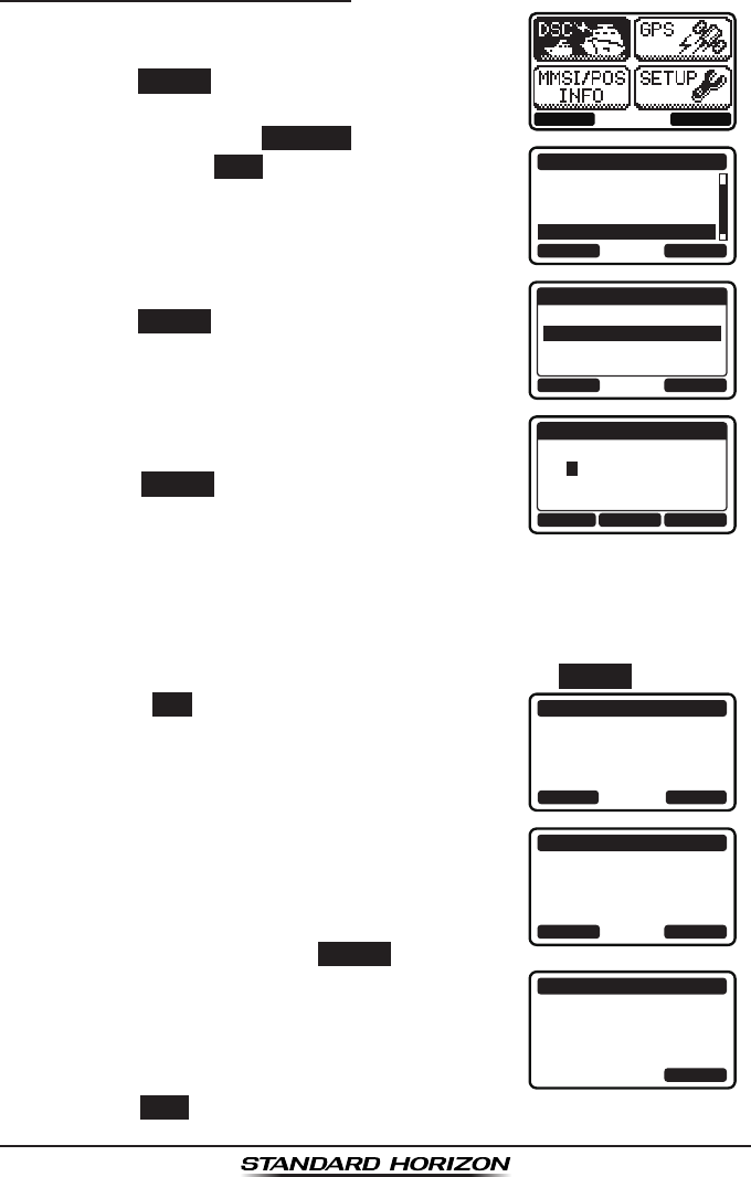
Page 77GX1300
DSC Test Call - Manual MMSI Entry
1. Press the MENU key to display the menu.
BACK SELECT
BACK SELECT
DSC CALL
POS REQUEST
POS REPORT
AUTO POS POLLING
TEST CALL
2. Press the ▲ / ▼ keys to select “DSC”, then
press the SELECT soft key.
3. Press the ▲ / ▼ keys to select “TEST CALL”,
and then press the SELECT
soft key. (To
cancel, press the BACK soft key.)
4. Press the ▲ / ▼ keys to select “NEW ID”, then
press the SELECT soft key.
BACK SELECT
TEST CALL
MEMORY
NEW ID
5. Press the ▲ / ▼ keys to scroll through
numbers, 0 to 9.
BACK SELECTFINISH
NEW ID
MMSI:
3----------
6. Press the SELECT soft key to store the number
and step to the next digit to the right.
7. Repeat steps 5 and 6 until the MMSI is complete.
If a mistake was made entering in the MMSI number, press the ◄ / ►
keys repeatedly until the wrong number is highlighted, then press the ▲
/ ▼ keys to correct the entry.
8. After the nineth number has been entered, press the FINISH soft key.
9. Press the YES soft key to transmit the test
signal.
TEST CALL
366901555
CATEG: SAFETY
Transmit a Call?
YE
SN
O
10. After the DSC test call is transmitted, the
GX1300 waits for a reply from the radio which
was called, and the display will show “WAITING
FOR ACK”.
To transmit again, press the RESEND soft key.
TEST CALL
366901555
CATEG: SAFETY
SINCE: 00:05
[Waiting for ACK]
RESEND QUIT
11. When an acknowledgement signal is received,
the display will show “Received ACK”.
TEST CALL
366901555
CATEG: SAFETY
SINCE: 00:05
[ Received ACK ]
QUIT
12. Press the QUIT soft key to return to the radio operation.

GX1300Page 78
9.11.2 Receiving a DSC Test Call
When another vessel transmits a DSC test call
to the GX1300, the radio automatically reply an
acknowledgement. The display shows the MMSI
or the name of the vessel transmitting the DSC
test call.
RX TEST CALL
YAESU
DSC TEST REPLY
SINCE: 00:05
[ Transmitted ]
QUIT
Press the QUIT soft key to return to radio operation.
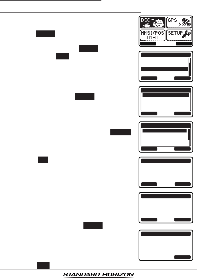
Page 79GX1300
9.12 POLLING CALL
The GX1300 has the capability to transmit a signal ensuring that another
DSC radio is able to accept channel communication.
9.12.1 Transmitting a Polling Call
Position Polling from Individual / Position Call Directory
1. Press the MENU key to display the menu.
BACK SELECT
BACK SELECT
DSC CALL
AUTO POS POLLING
TEST CALL
POLLING CALL
DSC LOG
2. Press the ▲ / ▼ keys to select “DSC”, then
press the SELECT soft key.
3. Press the ▲ / ▼ keys to select “POLLING
CALL”, and then press the SELECT soft key. (To
cancel, press the BACK soft key.)
4. Press the ▲ / ▼ keys to select “HISTORY” or
“MEMORY”, then press the SELECT soft key.
BACK SELECT
POLLING CALL
HISTORY
MEMORY
NEW ID
5. Press the ▲ / ▼ keys to select an individual
you want to contact, then press the SELECT
soft key.
BACK SELECT
MEMORY
YAESU
USCG
MEMORY SHIPS
HORIZON
6. Press the YES soft key to transmit the polling
signal.
POLLING CALL
YAESU
CATEG: ROUTINE
Transmit a Call?
YE
SN
O
7. After the polling call is transmitted, the
GX1300 waits for a reply from the radio which
was called, and the display will show “WAITING
FOR ACK”.
To transmit again, press the RESEND soft key.
POLLING CALL
YAESU
CATEG: ROUTINE
SINCE: 00:05
[Waiting for ACK]
RESEND QUIT
8. When an acknowledgement signal is received,
the display will show “Received ACK”.
POLLING CALL
YAESU
CATEG: ROUTINE
SINCE: 00:05
[ Received ACK ]
QUIT
9. Press the QUIT soft key to return to the radio operation.
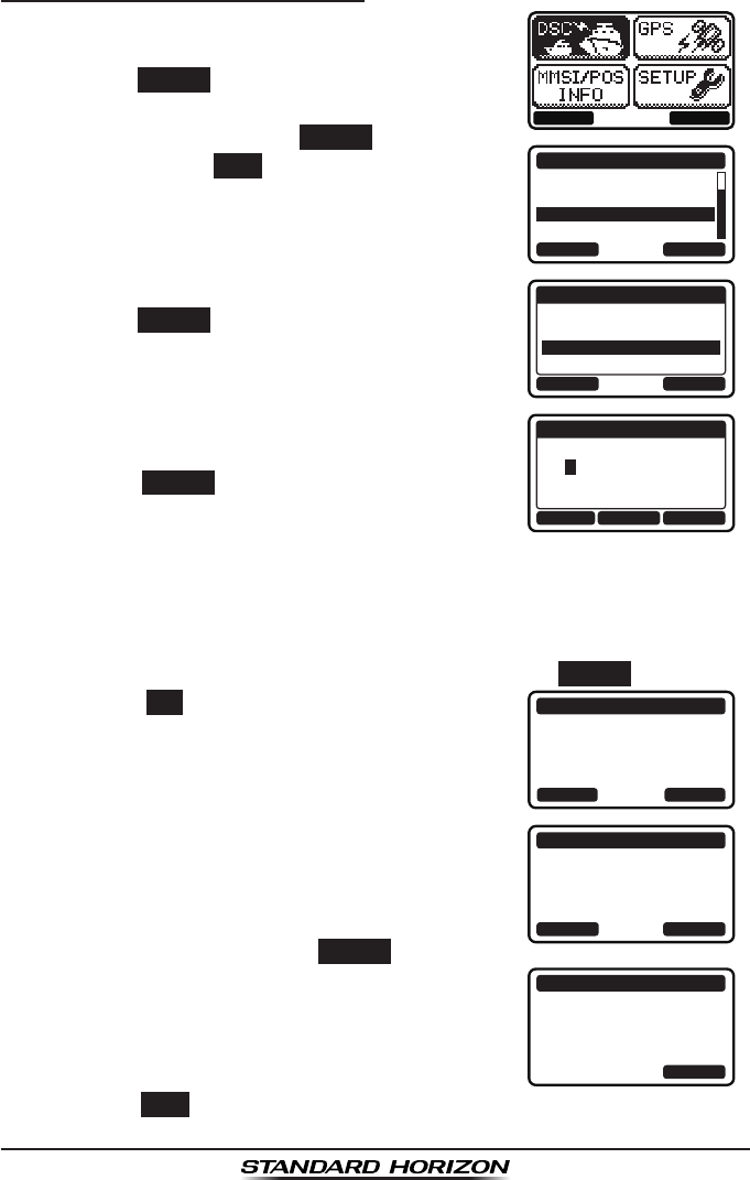
GX1300Page 80
Position Polling - Manual MMSI Entry
1. Press the MENU key to display the menu.
BACK SELECT
BACK SELECT
DSC CALL
AUTO POS POLLING
TEST CALL
POLLING CALL
DSC LOG
2. Press the ▲ / ▼ keys to select “DSC”, then
press the SELECT soft key.
3. Press the ▲ / ▼ keys to select “POLLING
CALL”, and then press the SELECT soft key. (To
cancel, press the BACK soft key.)
4. Press the ▲ / ▼ keys to select “NEW ID”, then
press the SELECT soft key.
BACK SELECT
POLLING CALL
HISTORY
MEMORY
NEW ID
5. Press the ▲ / ▼ keys to scroll through
numbers, 0 to 9.
BACK SELECTFINISH
NEW ID
MMSI:
3----------
6. Press the SELECT soft key to store the number
and step to the next digit to the right.
7. Repeat steps 5 and 6 until the MMSI is complete.
If a mistake was made entering in the MMSI number, press the ◄ / ►
keys repeatedly until the wrong number is highlighted, then press the ▲
/ ▼ keys to correct the entry.
8. After the nineth number has been entered, press the FINISH soft key.
9. Press the YES soft key to transmit the polling
signal.
POLLING CALL
366901555
CATEG: ROUTINE
Transmit a Call?
YE
SN
O
10. After the polling call is transmitted, the
GX1300 waits for a reply from the radio which
was called, and the display will show “WAITING
FOR ACK”.
To transmit again, press the RESEND soft key.
POLLING CALL
366901555
CATEG: ROUTINE
SINCE: 00:05
[Waiting for ACK]
RESEND QUIT
11. When an acknowledgement signal is received,
the display will show “Received ACK”.
POLLING CALL
366901555
CATEG: ROUTINE
SINCE: 00:05
[ Received ACK ]
QUIT
12. Press the QUIT soft key to return to the radio operation.

Page 81GX1300
9.12.2 Receiving a Polling Call
When another vessel transmits a polling call to the
GX1300, the radio automatically reply an acknowl-
edgement. The display shows the MMSI or the
name of the vessel transmitting the polling call.
RX POLLING CALL
YAESU
POLLING REPLY
SINCE: 00:05
[ Transmitted ]
QUIT
Press the QUIT soft key to return to radio operation.
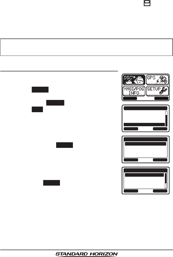
GX1300Page 82
9.13 DSC LOG OPERATION
The GX1300 logs transmitted DSC calls, received distress calls, and other
calls (individual, group, all ships, etc.). The DSC log feature is similar to an
answer machine where calls are recorded for review and a “” icon will
appear on the radio's display. The GX1300 can store up to the latest 20
transmitted calls, up to the latest 20 distress calls, and up to the latest 38
other calls.
NOTE
9.13.1 Reviewing a Logged Transmitted Call
1. Press the MENU key to display the menu.
BACK SELECT
BACK SELECT
DSC CALL
AUTO POS POLLING
TEST CALL
POLLING CALL
DSC LOG
2. Press the ▲ / ▼ keys to select “DSC”, then
press the SELECT soft key.
3. Press the ▲ / ▼ keys to select “DSC LOG”, and
then press the SELECT soft key. (To cancel,
press the BACK soft key.)
4. Press the ▲ / ▼ key to select “TRANSMITTED
LOG”, then press the SELECT soft key.
BACK SELECT
DSC LOG
TRANSMITTED LOG
DISTRESS LOG
OTHER CALL LOG
LOG DELETE
5. Press the ▲ / ▼ key to select the station (name
or MMSI number) you want to review the call,
then press the SELECT soft key.
BACK SELECT
TRANSMITTED LOG
HORIZON
MEMORY SHIPS
USCG
YAESU
When the “DSC LOG” menu is selected, the GX1300 may display high-
priority logged call automatically.
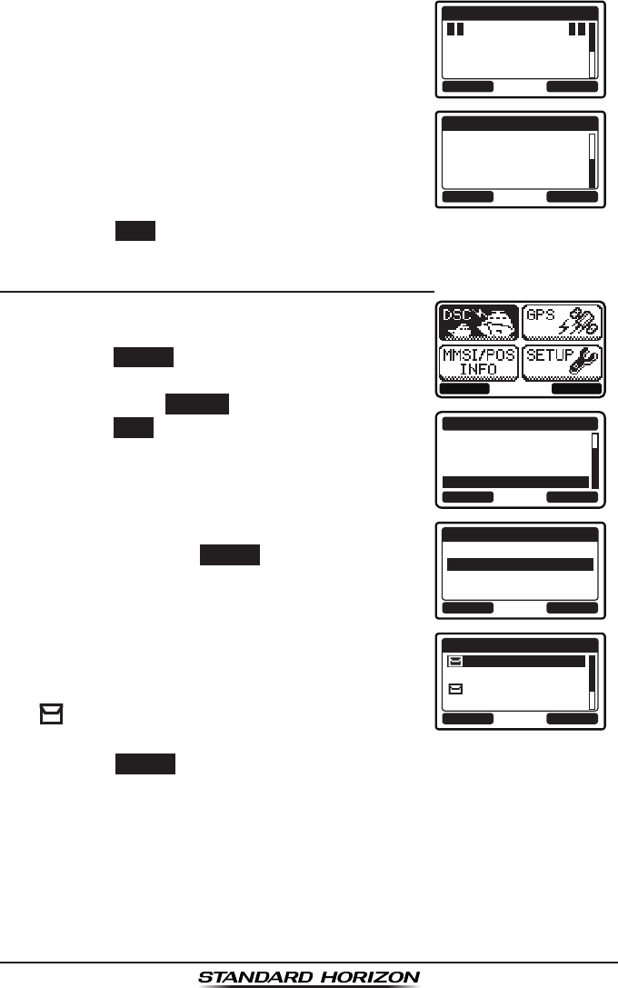
Page 83GX1300
6. Press the ▲ / ▼ key to scroll the display.
BACK DELETE
TRANSMITTED LOG
INDIVIDUAL
123456789
YAESU
TX TM: 12:56 UTC
BACK DELETE
TRANSMITTED LOG
DATE: 12/JAN
CATER: ROUTINE
CH: 06
[ Delayed ACK ]
7. Press the BACK soft key to go back to the DSC transmitted call list.
9.13.2 Reviewing a Logged DSC Distress Call
1. Press the MENU key to display the menu.
BACK SELECT
BACK SELECT
DSC CALL
AUTO POS POLLING
TEST CALL
POLLING CALL
DSC LOG
2. Press the ▲ / ▼ keys to select “DSC”, then
press the SELECT soft key.
3. Press the ▲ / ▼ keys to select “DSC LOG”, and
then press the SELECT soft key. (To cancel,
press the BACK soft key.)
4. Press the ▲ / ▼ key to select “DISTRESS
LOG”, then press the SELECT soft key.
BACK SELECT
DSC LOG
TRANSMITTED LOG
DISTRESS LOG
OTHER CALL LOG
LOG DELETE
5. Press the ▲ / ▼ key to select the station (name
or MMSI number) you want to review.
Note: When there is an unread received call,
“” icon will appear at the head of the station
name (or MMSI number).
BACK SELECT
DISTRESS LOG
HORIZON
MEMORY SHIPS
USCG
YAESU
Press the SELECT soft key to review details for the selected station.
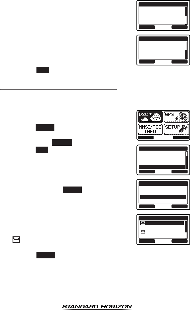
GX1300Page 84
6. Press the ▲ / ▼ key to scroll the display.
BACK DELETE
DISTRESS LOG
123456789
YAESU
RX TM: 12:56 UTC
DATE: 12/JAN
BACK DELETE
DISTRESS LOG
DATE: 12/JAN
CATER: ROUTINE
CH: 06
[ Delayed ACK ]
7. Press the BACK soft key to go back to the DSC distress call list.
9.13.3 Reviewing a Logged Other Calls
The GX1300 allows received calls (individual, group, all ships, etc.) to be
reviewed.
1. Press the MENU key to display the menu.
BACK SELECT
BACK SELECT
DSC CALL
AUTO POS POLLING
TEST CALL
POLLING CALL
DSC LOG
2. Press the ▲ / ▼ keys to select “DSC”, then
press the SELECT soft key.
3. Press the ▲ / ▼ keys to select “DSC LOG”, and
then press the SELECT soft key. (To cancel,
press the BACK soft key.)
4. Press the ▲ / ▼ key to select “OTHER CALL
LOG”, then press the SELECT soft key.
BACK SELECT
DSC LOG
TRANSMITTED LOG
DISTRESS LOG
OTHER CALL LOG
LOG DELETE
5. Press the ▲ / ▼ key to select the station (name
or MMSI number) you want to review.
Note: When there is an unread received call,
“” icon will appear at the head of the station
name (or MMSI number).
BACK SELECT
OTHER CALL LOG
HORIZON
MEMORY SHIPS
USCG
YAESU
Press the SELECT soft key, to review details for the selected station.
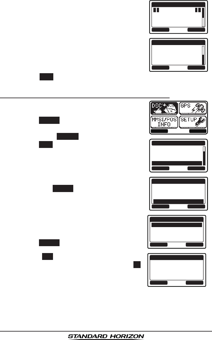
Page 85GX1300
6. Press the ▲ / ▼ key to scroll the display.
BACK DELETE
RX OTHER LOG
INDIVIDUAL
123456789
YAESU
RX TM: 12:56 UTC
BACK DELETE
RX OTHER LOG
DATE: 12/JAN
CATER: ROUTINE
CH: 06
[ Delayed ACK ]
7. Press the BACK soft key to go back to the DSC other call list.
9.13.4 Deleting Calls from the “DSC LOG” Directory
1. Press the MENU key to display the menu.
BACK SELECT
BACK SELECT
DSC CALL
AUTO POS POLLING
TEST CALL
POLLING CALL
DSC LOG
2. Press the ▲ / ▼ keys to select “DSC”, then
press the SELECT soft key.
3. Press the ▲ / ▼ keys to select “DSC LOG”, and
then press the SELECT soft key. (To cancel,
press the BACK soft key.)
4. Press the ▲ / ▼ key to select “LOG DELETE”,
then press the SELECT soft key.
BACK SELECT
DSC LOG
TRANSMITTED LOG
DISTRESS LOG
OTHER CALL LOG
LOG DELETE
5. Press the ▲ / ▼ key to select the category
(“TRANSMITTED LOG”, “DISTRESS LOG”, “OTHER
CALL LOG”, or “ALL LOG”) to be deleted, then
press the SELECT soft key. BACK SELECT
LOG DELETE
TRANSMITTED LOG
DISTRESS LOG
OTHER CALL LOG
ALL LOG
6. Press the YES soft key to delete logs of the
selected category. (To cancel, press the NO
soft key.)
YE
SN
O
LOG DELETE
TRANSMITTED LOG
Do you want to
delete it?

GX1300Page 86
7. Press the OK soft key to go back to the catego-
ry list.
OK
LOG DELETE
TRANSMITTED LOG
Complete
NOTE
The procedure above will delete logged calls of the selected category
all at once.
To delete logged calls one by one, review details of a call you want to
delete, then press the DELETE soft key.
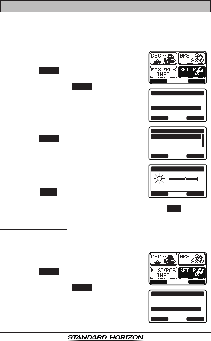
Page 87GX1300
10 SETUP MENU
10.1 CONFIGURATION SETUP
10.1.1 Lamp Adjusting
Allows adjustment of the backlight intensity or to turn it off.
1. Press the MENU key to display the menu.
BACK SELECT
BACK SELECT
SETUP
DSC SETUP
CHANNEL SETUP
CONFIGURATION
2. Press the ▲ / ▼ keys to select “SETUP”, then
press the SELECT soft key.
3. Press the ▲ / ▼ keys to select “CONFIGURA-
TION”, then press the SELECT soft key.
4. Select “DIMMER” with the ▲ / ▼ keys, then
press the SELECT soft key.
BACK SELECT
CONFIGURATION
DIMMER
CONTRAST
KEY BEEP
LOCATION FORMT
5. Press the ▲ / ▼ keys to select the desired
level. When “OFF” is selected, the lamp is
extinguished. 5
BACK ENTER
DIMMER
6. Press the ENTER soft key to store the selected
level.
7. To exit this menu and return to radio operation press the BACK soft key.
10.1.2 LCD Contrast
This selection sets up the display for best viewabilty for the varying mounting
locations (overhead or below).
1. Press the MENU key to display the menu.
BACK SELECT
BACK SELECT
SETUP
DSC SETUP
CHANNEL SETUP
CONFIGURATION
2. Press the ▲ / ▼ keys to select “SETUP”, then
press the SELECT soft key.
3. Press the ▲ / ▼ keys to select “CONFIGURA-
TION”, then press the SELECT soft key.
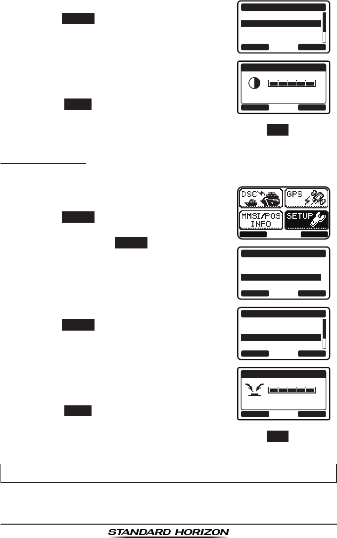
GX1300Page 88
4. Select “CONTRAST” with the ▲ / ▼ keys, then
press the SELECT soft key.
BACK SELECT
CONFIGURATION
DIMMER
CONTRAST
KEY BEEP
LOCATION FORMT
5. Press the ▲ / ▼ keys to select the desired
level. The contrast level can be set from “00”
to “25”. 25
BACK ENTER
CONTRAST
6. Press the ENTER soft key to store the selected
level.
7. To exit this menu and return to radio operation press the BACK soft key.
10.1.3 Key Beep
This section allows the level of the key beep to be adjusted or turned off.
1. Press the MENU key to display the menu.
BACK SELECT
BACK SELECT
SETUP
DSC SETUP
CHANNEL SETUP
CONFIGURATION
2. Press the ▲ / ▼ keys to select “SETUP”, then
press the SELECT soft key.
3. Press the ▲ / ▼ keys to select “CONFIGURA-
TION”, then press the SELECT soft key.
4. Select “KEY BEEP” with the ▲ / ▼ keys, then
press the SELECT soft key.
BACK SELECT
CONFIGURATION
DIMMER
CONTRAST
KEY BEEP
LOCATION FORMT
5. Press the ▲ / ▼ keys to select the desired
beep level. The key beep level can be set from
“0” (OFF) to “5”. 5
BACK ENTER
KEY BEEP
6. Press the ENTER soft key to store the selected
level.
7. To exit this menu and return to radio operation press the BACK soft key.
NOTE
Emergency alarm and beeps for DSC operation cannot be turned OFF.
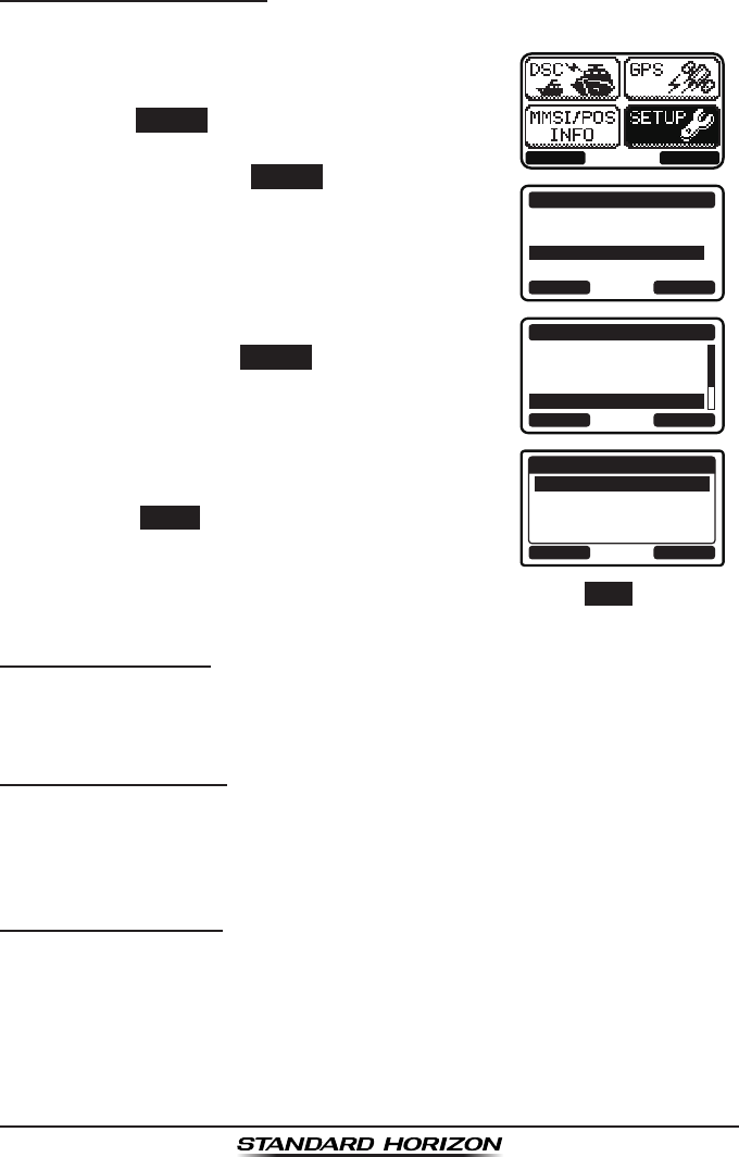
Page 89GX1300
10.1.4 Location Format
This selection sets the coordinate system to be shown on the LCD.
1. Press the MENU key to display the menu.
BACK SELECT
BACK SELECT
SETUP
DSC SETUP
CHANNEL SETUP
CONFIGURATION
2. Press the ▲ / ▼ keys to select “SETUP”, then
press the SELECT soft key.
3. Press the ▲ / ▼ keys to select “CONFIGURA-
TION”, then press the SELECT soft key.
4. Select “LOCATION FORMAT” with the ▲ / ▼
keys, then press the SELECT soft key.
BACK SELECT
CONFIGURATION
DIMMER
CONTRAST
KEY BEEP
LOCATION FORMT
5. Press the ▲ / ▼ keys to select the desired
coordinate system.
BACK ENTER
LOCATION FORMAT
dd°mm.mmm
dd°mm.mm
dd°mm’SS”
6. Press the ENTER soft key to store the selected
level.
7. To exit this menu and return to radio operation press the BACK soft key.
10.1.5 Time Offset
This selection sets the time offset from UTC (time GPS sends to radio).
Refer to section “6.6 CHANGING THE GPS TIME” for details.
10.1.6 Time Display
This selection selects the time area between the local time and the UTC
time.
Refer to section “6.7 CHANGING THE TIME LOCATION” for details.
10.1.7 Time Format
This selection selects the time format between the 12-hour system and the
24-hour system.
Refer to section “6.8 CHANGING THE TIME FORMAT” for details.
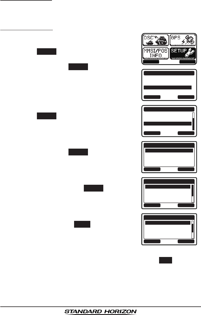
GX1300Page 90
10.1.8 Soft Keys
This menu item assigns the number of soft keys, soft key selection and how
long the display will show the soft key icon after a soft key is pressed.
Assigning Soft Keys
1. Press the MENU key to display the menu.
BACK SELECT
BACK SELECT
SETUP
DSC SETUP
CHANNEL SETUP
CONFIGURATION
2. Press the ▲ / ▼ keys to select “SETUP”, then
press the SELECT soft key.
3. Press the ▲ / ▼ keys to select “CONFIGURA-
TION”, then press the SELECT soft key.
4. Select “SOFT KEY” with the ▲ / ▼ keys, then
press the SELECT soft key.
BACK SELECT
CONFIGURATION
TIME AREA
TIME FORMAT
SOFT KEY
RESET
5. Press the ▲ / ▼ keys to select “KEY ASSIGN-
MENT”, then press the SELECT soft key.
BACK SELECT
SOFT KEY
KEY ASSIGNMENT
KEY TIMMER
6. Press the ▲ / ▼ keys to select the desired soft
key number, then press the SELECT soft key.
BACK ENTER
KEY ASSIGNMENT
1: WX/CH
2: DW/TW
3: SCAN
4: SCAN MEMORY
7. Press the ▲ / ▼ keys to select the desired key
function, then press the ENTER soft key.
Refer to the next page for available functions.
BACK ENTER
KEY ASSIGNMENT
WX/CH
DW/TW
SCAN
SCAN MEMORY
8. Repeat steps 6 and 7 to assign up to 6 functions.
9. To exit this menu and return to radio operation press the BACK soft key.
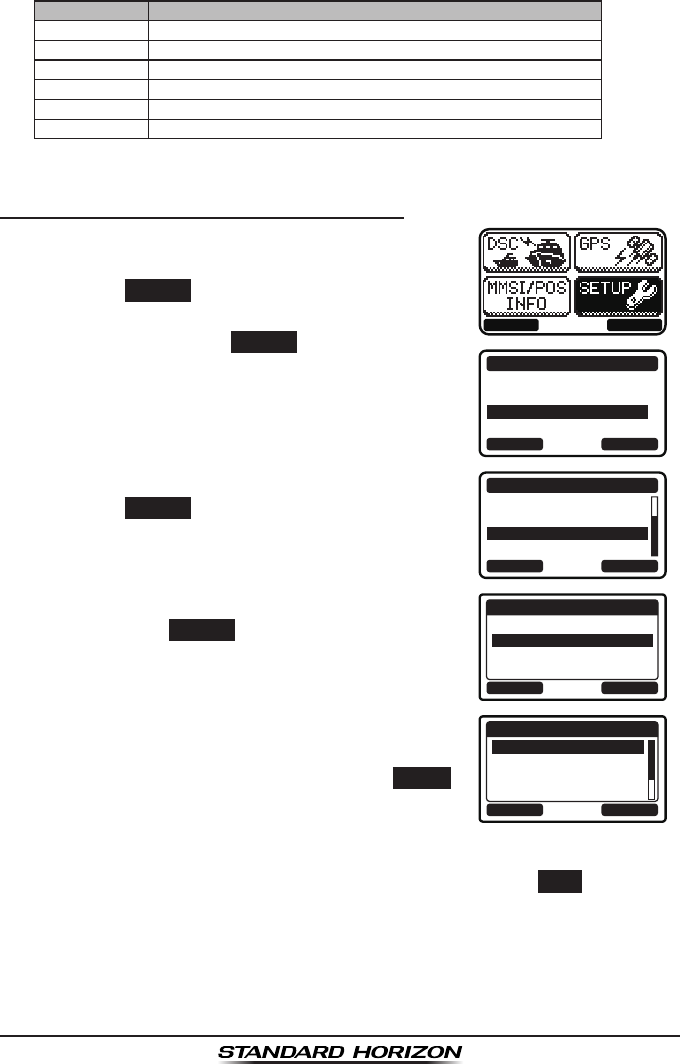
Page 91GX1300
Available functions are:
DISPLAY FUNCTION
WX/CH Switches channels between weather and marine.
HI/LO Switches transmit power.
SCAN Starts and stops scanning.
DW/TW Starts and stops the dual or triple watch scan.
MEM Switches on and off of the memory channel scan.
PRESET Saves or deletes the preset memory channel.
Selecting How Long the Soft Keys are Shown
1. Press the MENU key to display the menu.
BACK SELECT
BACK SELECT
SETUP
DSC SETUP
CHANNEL SETUP
CONFIGURATION
2. Press the ▲ / ▼ keys to select “SETUP”, then
press the SELECT soft key.
3. Press the ▲ / ▼ keys to select “CONFIGURA-
TION”, then press the SELECT soft key.
4. Select “SOFT KEY” with the ▲ / ▼ keys, then
press the SELECT soft key.
BACK SELECT
CONFIGURATION
TIME AREA
TIME FORMAT
SOFT KEY
RESET
5. Press the ▲ / ▼ keys to select “KEY TIMER”,
then press the SELECT soft key.
BACK SELECT
SOFT KEY
KEY ASSIGNMENT
KEY TIMMER
6. Press the ▲ / ▼ keys to select how long the
soft key icon will be shown on the display after
a soft key is pressed, then press the ENTER
soft key.
The showing time can be set to “3 sec”, “5
sec”, “7 sec”, “10 sec”, or “15 sec”.
BACK ENTER
KEY TIMMER
3 sec
5 sec
7 sec
10 sec
7. To exit this menu and return to radio operation press the BACK soft key.
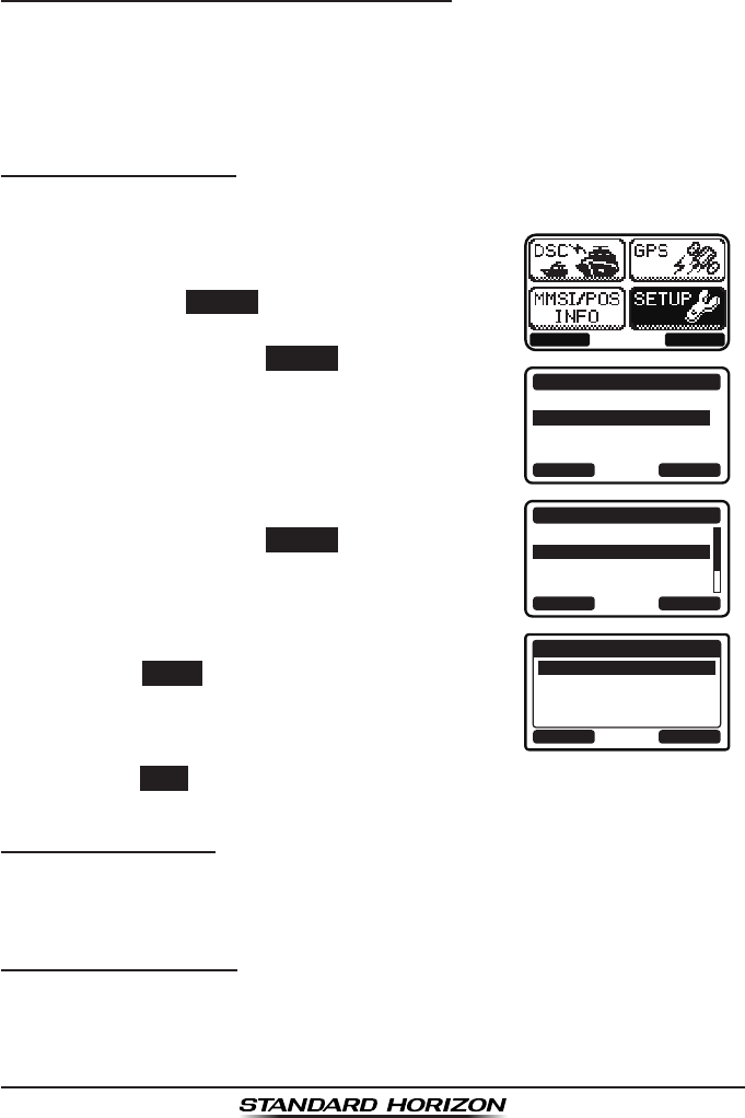
GX1300Page 92
10.2 CHANNEL SETUP
10.2.1 Channel Group (Band Selection)
This selection allows you to change the channel group from International to
USA or Canada.
Refer to section “8.5 INTERNATIONAL, USA, AND CANADA MODE” for
details.
10.2.2 Weather Alert
This selection is used to enable or disable the NOAA Weather Alert function.
1. Press the MENU key to display the menu.
BACK SELECT
BACK SELECT
SETUP
DSC SETUP
CHANNEL SETUP
CONFIGURATION
2. Select “SETUP” with the ▲ / ▼ / ◄ / ► keys,
then press the SELECT soft key.
3. Press the ▲ / ▼key to select “CHANNEL
SETUP”, then press the SELECT soft key.
4. Press the ▲ / ▼ key to select “WEATHER
ALERT”, then press the SELECT soft key.
BACK SELECT
CHANNEL SETUP
CHANNEL GROUP
WEATHER ALERT
MULTI WATCH
SCAN MEMORY
5. Press the ▲ / ▼ keys to select “ON” or “OFF”.
BACK ENTER
WEATHER ALERT
OFF
ON
6. Press the ENTER soft key to store the selected
setting.
7. Press the BACK soft key to exit the menu and return to radio operation.
10.2.3 Multi Watch
Allows selection of the dual and triple watch functions.
Refer to section “8.8 MULTI WATCH (TO PRIORITY CHANNEL)” for details.
10.2.4 Scan Memory
To be able to scan channels the radio must be programmed. This section
allows channels to be stored in scan memory.
Refer to section “8.7.2 Scan Memory Programming” for details.
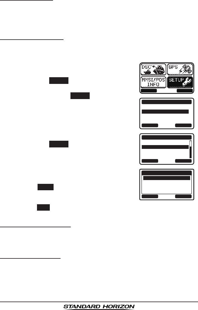
Page 93GX1300
10.2.5 Scan Type
This selection is used to select the scan mode between “Memory Scan” and
“Priority Scan”.
Refer to section “8.7.1 Selecting the Scan Type” for details.
10.2.6 Scan Resume
This selection is used to select the time the GX1300 waits after a transmis-
sion ends before the radio start to scan channels again.
1. Press the MENU key to display the menu.
BACK SELECT
BACK SELECT
SETUP
DSC SETUP
CHANNEL SETUP
CONFIGURATION
2. Select “SETUP” with the ▲ / ▼ / ◄ / ► keys,
then press the SELECT soft key.
3. Press the ▲ / ▼key to select “CHANNEL
SETUP”, then press the SELECT soft key.
4. Press the ▲ / ▼ key to select “SCAN RESUME”,
then press the SELECT soft key.
BACK SELECT
CHANNEL SETUP
SCAN TYPE
SCAN RESUME
PRIORITY CH
SUB CH
5. Press the ▲ / ▼ keys to select the desired
resume time.
BACK ENTER
SCAN RESUME
1 sec
2 sec
3 sec
5 sec
6. Press the ENTER soft key to store the selected
setting.
7. Press the BACK soft key to exit the menu and return to radio operation.
10.2.7 Priority Channel
Allows selection of the priority channel.
Refer to section “8.7.4 Priority Channel Setting” for details.
10.2.8 Sub Channel
Allows selection of the sub channel. The default setting is Channel 9.
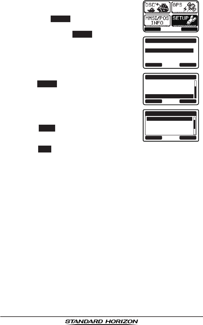
GX1300Page 94
1. Press the MENU key to display the menu.
BACK SELECT
BACK SELECT
SETUP
DSC SETUP
CHANNEL SETUP
CONFIGURATION
2. Select “SETUP” with the ▲ / ▼ / ◄ / ► keys,
then press the SELECT soft key.
3. Press the ▲ / ▼key to select “CHANNEL
SETUP”, then press the SELECT soft key.
4. Press the ▲ / ▼ key to select “SUB CH”, then
press the SELECT soft key.
BACK SELECT
CHANNEL SETUP
SCAN TYPE
SCAN RESUME
PRIORITY CH
SUB CH
5. Press the ▲ / ▼ keys to select the sub
channel.
BACK ENTER
SUB CH
CH: 9
CH: 10
CH: 11
CH: 12
S-CH
6. Press the ENTER soft key to store the selected
setting.
7. Press the BACK soft key to exit the menu and return to radio operation.

Page 95GX1300
10.3 DSC SETUP
10.3.1 Individual Directory
The GX1300 has a DSC directory that allows you to store a vessel or
person’s name and the MMSI number associated with vessels you wish to
transmit individual calls, position requests and position report transmissions.
To transmit an individual call you must program this directory with information
of the persons you wish to call, similar to a cellular phones telephone direc-
tory.
Refer to section “9.5.1 Setting up the Individual / Position Call Directory”
for programming.
10.3.2 Individual Reply
This menu item sets up the radio to automatically (default setting) or manual-
ly respond to a DSC individual call requesting you to switch to a working
channel for voice communications. When the manual response is selected
the MMSI of the calling vessel is shown allowing you to see who is calling.
This function is similar to caller id on a cellular phone.
Refer to section “9.5.2 Setting up Individual Call Reply” for setting.
10.3.3 Individual Acknowledgement
The radio can be setup to transmit a reply automatically (default) or set so
the radio will not reply to an individual call.
Refer to section “9.5.3 Setting up the Individual Acknowledge Message”
for setting.
10.3.4 Individual Ringer
The radio can be setup to ring like a telephone to alert you the radio received
a DSC individual call. The default setting is 2 minutes, however this can be
changed to 15, 10 or 5 seconds.
Refer to section “9.5.6 Setting up Individual Call Ringer” for setting.

GX1300Page 96
10.3.5 Group Directory
For this function to operate, the same group MMSI must be programmed
into all the DSC VHF radios within the group of vessels that will be using this
feature. To understand group MMSI programming, rst a ship MMSI has to
be understood.
Refer to section “9.6.1 Setting up a Group Call” for programming.
10.3.6 Auto Position Polling Call Type
The GX1300 has the capability to automatically track four vessels
programmed into the individual directory. This selection allows you to select
the call type used in the auto position polling.
Refer to section “9.10.1 Setting up the Polling Call Type” for setting.
10.3.7 Auto Position Polling Interval Time
The GX1300 has the capability to automatically track four vessels
programmed into the individual directory. This selection allows you to select
time interval between polling call transmissions.
Refer to section “9.10.2 Setting up the Polling Time Interval” for setting.
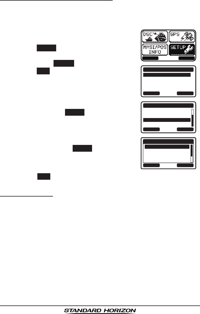
Page 97GX1300
10.3.8 Auto Channel Switching Time
When a DSC distress call or an all ships call (urgency or safety) is received,
the GX1300 will automatically switch to the channel 16.
This menu selection allows the automatic switching time to be changed.
1. Press the MENU key to display the menu.
BACK SELECT
BACK SELECT
SETUP
DSC SETUPGROUP
CHANNEL SETUP
CONFIGURATION
2. Press the ▲ / ▼ keys to select “SETUP”, then
press the SELECT soft key.
3. Press the ▲ / ▼ keys to select “DSC SETUP”,
then press the SELECT soft key. (To cancel,
press the BACK soft key.)
4. Select “CH SWITCH TIMER” with the ▲ / ▼
keys, then press the SELECT soft key.
BACK SELECT
DSC SETUP
AUTP POS POLL
AUTO POS TIME
CH SWITCH TIMER
DSC BEEP
5. Press the ▲ / ▼ keys to select the desired
time, then press the ENTER
soft key. The
switching time can be set to “10 sec”, “30
sec”, “1 min”, “2 min”, or “OFF”. BACK ENTER
CH SWITCH TIMER
OFF
10 sec
30 sec
1 min
6. Press the BACK soft key to exit the menu and return to radio operation.
10.3.9 DSC Beep
This feature allows the alarm beeps to be turned on (default setting) or off
when a DSC call is received. The DSC calls that can be customized are:
individual, group, all ships, position request, position report call.
Refer to section “9.6.4 Setting up the Group Call Ringer” for setting.

GX1300Page 98
11 MAINTENANCE
The inherent quality of the solid-state components used in this transceiver
will provide many years of continuous use. Taking the following precautions
however, will prevent damage to the transceiver.
• Never key the microphone unless an antenna or suitable dummy load is
connected to the transceiver.
• Ensure that the supply voltage to the transceiver does not exceed 16
VDC or fall below 11 VDC.
• Use only STANDARD HORIZON-approved accessories and replacement
parts.
In the unlikely event of serious problems, please contact your Dealer or our
repair facility.
11.1 REPLACEMENT PARTS
Commonly requested parts, and their part numbers are listed below.
• Power Cord: T9025406
• VOL/SQL Knob (Black): RA6018100
• VOL/SQL Knob (White): RA6018000
• Mounting Bracket (Black): RA097840A
• Mounting Bracket (White): RA097830A
• Mounting Bracket Knob (Black): RA0978600
• Mounting Bracket Knob (White): RA0978500
• Microphone Hanger (Black): RA0458800
• Microphone Hanger (White): RA0436000
11.2 FACTORY SERVICE
In the unlikely event that the radio fails to perform or needs servicing, please
contact your dealer.
An “RA” (Return Authorisation) number is not necessary to send a product
in for service. Include a brief note describing the problem along with your
name, return address, phone number, and proof of purchase.

Page 99GX1300
11.3 TROUBLESHOOTING CHART
SYMPTOM PROBABLE CAUSE REMEDY
Transceiver fails to
power up.
No DC voltage to the
transceiver, or blown
fuse.
a. Check the 12 VDC battery connections and
the fuse.
b. The VOL knob needs to be rotated clock-
wise to turn the radio on.
Transceiver blows
fuse when connected
to power supply.
Reversed power
wires.
Check the power cable for DC voltage, or re-
place the fuse (6 A 250 V).
Make sure the red wire is connected to the
positive (+) battery post, and the black wire is
connected to the negative (-) battery post. If
the fuse still blows, contact your Dealer.
Popping or whining
noise from the speak-
er while engine runs.
Engine noise. Reroute the DC power cables away from the
engine. Add noise suppressor on power cable.
Change to resistive spark plug wires and/or
add an alternator whine lter.
Sound is not emitted
from the internal or
external speaker.
Accessory cable. Check the connections of the accessory cable
(Possible short circuit on the External speaker
cable WHITE/SHIELD).
Receiving station
report low transmit
power, even with
transceiver set to HI
power.
Antenna. Have the antenna checked or test the trans-
ceiver with another antenna. If the problem
persists, contact your Dealer for servicing.
“HI BATTERY” or “LO
BATTERY” message
is appeared when the
power is turned on.
The power supply
voltage is too high or
too low.
Conrm that the connected power supply volt-
age is between 10 volts and 17 volts DC. Con-
rm that the generator has not malfunctioned.
Your position is not
displayed.
Accessory cable. Check the accessory cable connection.
Some GPS use the battery ground line for
NMEA connection.
Setting of the GPS
navigation receiver.
Check the output signal format of the GPS
navigation receiver. This radio requires
NMEA0183 format with GLL, RMC, GGA, or
GNS sentence as an output signal. If the GPS
has a baud rate setting make sure to select
4800 and parity to NONE.

GX1300Page 100
12 CHANNEL ASSIGNMENTS
Tables on the following columns list the VHF Marine Channel assignments for
U.S.A. and International use. Below are listed some data about the charts.
1. VTS. Where indicated, these channels are part of the U.S. Coast Guard’s
Vessel Trafc System.
2. Alpha channel numbers, that is, channel numbers followed by the letter A
(such as Channel 07A) are simplex channels on the U.S.A. or Canadian
channel assignments whose counterparts in the International assign-
ments are duplex channels. International channels do not use “alpha”
numbers. If you call the Coast Guard on Channel 16, they will sometimes
ask you to “go to channel 22 Alpha.” This is a channel assigned to U.S.A,
and Canadian Coast Guards for handling distress and other calls. If your
radio is set for International operation you will go to Channel 22 instead
of 22A, and will not be able to communicate with the Coast Guard. To
use Channel 22A, your radio must be set for USA or Canada operation,
usually by a U/I/C (USA/International/Canada) control or combination of
controls. Channel 22 (without an “A”) is an International duplex channel
for port operations. Some radios indicate an “A” adjacent to the alpha
channels on the display; on others “alpha” is not indicated but the proper
channel is selected based on the U/I/C setting.
3. Bridge-to-Bridge channels (for example, Channel 13) are for use by
bridge operators on inter-coastal waterways and rivers. It is also used
by marine vessels in the vicinity of these bridges for navigation and for
communicating with the bridge operators. Note that a limit of 1 Watt is
specied for these channels.
4. The S/D column on the chart indicates either S (simplex) or D (duplex).
Simplex means transmitting and receiving on the same frequency. Only
one party at a time can talk, unlike a telephone. Be sure to say “over”
and release your microphone push-to-talk switch at the end of each
transmission. Duplex operation involves the use of one frequency for
transmitting and a separate frequency for receiving. On channels speci-
ed as duplex on the charts, correct mode of operation is established
automatically by your radio when you select a channel; you cannot
change the mode. And you still must release the push-to-talk switch after
each transmission in order to listen to the radio.
5. Channels normally used by recreational boaters are those that include
the term “non-commercial” in the Channel Use column of the chart.
Some of these are shared with other users and some are used only in
certain geographic regions.

Page 101GX1300
6. Marine vessels equipped with VHF radios are required to monitor
Channel 16.
7. 156.050 MHz and 156.175 MHz are available for port operations and
commercial communications purposes when used only within the U.S.
Coast Guard designated Vessel Traffic Services (VTS) area of New
Orleans, on the lower Mississippi River from the various pass entrances
in the Gulf of Mexico to Devil’s Swamp Light at River Mile 242.4 above
head of passes near Baton Rouge.
8. 156.250 MHz is available for port operations communications use only
within the U.S. Coast Guard designated VTS radio protection areas of
New Orleans and Houston described in Sec. 80.383. 156.250 MHz is
available for intership port operations communications used only within
the area of Los Angeles and Long Beach harbors, within a 25- nautical
mile radius of Point Fermin, California.
9. 156.550 MHz, 156.600 MHz and 156.700 MHz are available in the
U.S. Coast Guard designated port areas only for VTS communications
and in the Great Lakes available primarily for communications relating
to the movement of ships in sectors designated by the St. Lawrence
Seaway Development Corporation or the U.S. Coast Guard. The use
of these frequencies outside VTS and ship movement sector protected
areas is permitted provided they cause no interference to VTS and ship
movement communications in their respective designated sectors.
10. Use of 156.875 MHz is limited to communications with pilots regard-
ing the movement and docking of ships. Normal output power must not
exceed 1 watt. 5: 156.375 MHz and 156.650 MHz are available primar-
ily for intership navigational communications. These frequencies are
available between coast and ship on a secondary basis when used on
or in the vicinity of locks or drawbridges. Normal output power must not
exceed 1 watt. Maximum output power must not exceed 10 watts for
coast stations or 25 watts for ship stations.
11. On the Great Lakes, in addition to bridge-to-bridge communications,
156.650 MHz is available for vessel control purposes in established
vessel trafc systems. 156.650 MHz is not available for use in the Missis-
sippi River from South Pass Lighted Whistle Buoy “2” and Southwest
Pass entrance Mid-channel Lighted Whistle Buoy to mile 242.4 above
Head of Passes near Baton Rouge. Additionally it is not available for
use in the Mississippi River-Gulf Outlet, the Mississippi River-Gulf Outlet
Canal, and the Inner Harbor Navigational Canal, except to aid the transi-
tion from these areas.

GX1300Page 102
12. Use of 156.375 MHz is available for navigational communications only
in the Mississippi River from South Pass Lighted Whistle Buoy “2” and
Southwest Pass entrance Mid channel Lighted Whistle Buoy to mile
242.4 above head of Passes near Baton Rouge, and in addition over the
full length of the Mississippi River-Gulf Outlet Canal from entrance to its
junction with the Inner Harbor Navigation Canal, and over the full length
of the Inner Harbor Navigation Canal from its junction with the Mississippi
River to its entry to Lake Pontchartrain at the New Seabrook vehicular
bridge.
13. Within 120 km (75 miles) of the United States/Canada border, in the area
of the Puget Sound and the Strait of Juan de Fuca and its approaches,
157.425 MHz is half of the duplex pair designated as Channel 88. In this
area, Channel 88 is available to ship stations for communications with
public coast stations only. More than 120 km (75 miles) from the United
States/Canada border in the area of the Puget Sound and the Strait of
Juan de Fuca, its approaches, the Great Lakes, and the St. Lawrence
Seaway, 157.425 MHz is available for intership and commercial commu-
nications. Outside Puget Sound area and its approaches and the Great
Lakes, 157.425 MHz is also available for communications between
commercial fishing vessels and associated aircraft while engaged in
commercial shing activities.
14. When the frequency 156.850 MHz is authorized, it may be used addition-
ally for search and rescue training exercises conducted by state or local
governments.
15. The frequency 156.850 MHz is additionally available to coast stations on
the Great Lakes for transmission of scheduled Coded Marine Weather
Forecasts (MAFOR), Great Lakes Weather Broadcast (LAWEB) and
scheduled Notices to Mariners or Bulletins. F3C and J3C emissions are
permitted. Coast Stations on the Great Lakes must cease weather broad-
casts which cause interference to stations operating on 156.800 MHz
until the interference problem is resolved.
16. The frequency 157.100 MHz is authorized for search and rescue train-
ing exercises by state or local government in conjunction with U.S. Coast
Guard stations. Prior U.S. Coast Guard approval is required. Use must
cease immediately on U.S. Coast Guard request.
17. The duplex pair for channel 20 (157.000/161.600 MHz) may be used for
ship to coast station communications.
18. Available for assignment to coast stations, the use of which is in accord
with an agreed program, for the broadcast of information to ship stations
concerning the environment.
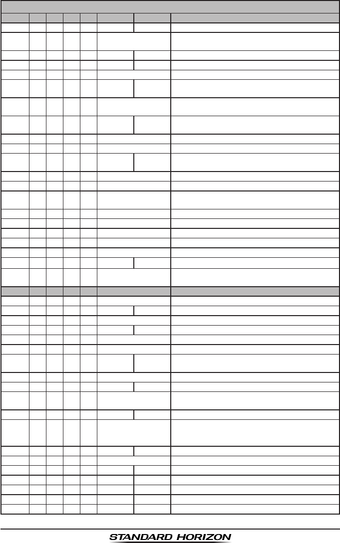
Page 103GX1300
VHF MARINE CHANNEL CHART
CH U C I S/D TX RX CHANNEL USE
01 X X D156.050 160.650 Public Correspondence (Marine Operator)
01A X S156.050 Port Operation and Commercial.
VTS in selected areas
02 X X D156.100 160.700 Public Correspondence (Marine Operator)
03 X X D156.150 160.750 Public Correspondence (Marine Operator)
03A X S 156.150 U.S. Government Only, Coast Guard
04 X D156.200 160.800 Public Correspondence (Marine Operator),
Port operation, ship movement
04A X S156.200 Pacic coast: Coast Guard, East Coast:
Commercial shing
05 X D156.250 160.850 Public Correspondence (Marine Operator),
Port operation, ship movement
05A X X S156.250 Port operation. VTS in Seattle
06 XXXS156.300 Inter-ship Safety
07 X D156.350 160.950 Public Correspondence (Marine Operator),
Port operation, ship movement
07A X X S156.350 Commercial
08 XXXS156.400 Commercial (Inter-ship only)
09 XXXS156.450 Boater Calling channel, Commercial &
Non-commercial (Recreational)
10 XXXS156.500 Commercial
11 XXXS156.550 Commercial. VTS in selected areas
12 XXXS156.600 Port operation. VTS in selected areas
13 XXXS156.650 Inter-ship Navigation Safety (Bridge-to-bridge)
14 XXXS156.700 Port operation. VTS in selected areas
15 XS- - - 156.750 Environmental (Receive only)
15 XXS156.750 Commercial, non-commercial,
ship movement (1 W)
16 XXXS156.800 International Distress, Safety and Calling
17 XXXS156.850 State Controlled (1 W)
18 X D156.900 161.500 Port operation, ship movement
18A X X S156.900 Commercial
19 X D156.950 161.550 Port operation, ship movement
19A X S156.950 US: Commercial
19A X S156.950 Coast Guard
20 X X X D157.000 161.600 Canadian Coast Guard Only,
International: port operations and shipment
20A X S157.000 Port operation
21 X D157.050 161.650 Port operation, ship movement
21A X X S 157.050 U.S. Government Only,
Canadian Coast Guard
22 X D157.100 161.700 Port operation, ship movement
22A X X S157.100 US and Canadian Coast Guard Liaison
and aritime Safety Information Broadcasts
announced on channel 16
23 X X D157.150 161.750 Public Correspondence (Marine Operator)
23A X S 157.150 U.S. Government Only
24 X X X D157.200 161.800 Public Correspondence (Marine Operator)
25 X X X D157.250 161.850 Public Correspondence (Marine Operator)
26 X X X D157.300 161.900 Public Correspondence (Marine Operator)
27 X X X D157.350 161.950 Public Correspondence (Marine Operator)
28 X X X D157.400 162.000 Public Correspondence (Marine Operator)

GX1300Page 104
VHF MARINE CHANNEL CHART
CH U C I S/D TX RX CHANNEL USE
60 X X D156.025 160.625 Public Correspondence (Marine Operator)
61 X D156.075 160.675 Public Correspondence (Marine Operator),
Port operation, ship movement
61A X X S 156.075 Public Coast: Coast Guard;
East Coast: commercial shing only
62 X D156.125 160.725 Public Correspondence (Marine Operator),
Port operation, ship movement
62A X S156.125 Public Coast: Coast Guard;
East Coast: commercial shing onl
63 X D156.175 160.775 Public Correspondence (Marine Operator),
Port operation, ship movement
63A X X S156.175 Port Operation and Commercial.
VTS in selected areas
64 X X D156.225 160.825 Public Correspondence (Marine Operator),
Port operation, ship movement
64A X X S 156.225 Public Correspondence (Marine Operator),
Port operation, ship movement
65 X D156.275 160.875 Public Correspondence (Marine Operator),
Port operation, ship movement
65A X X S156.275 Port Operations
66 X D156.325 160.925 Public Correspondence (Marine Operator),
Port operation, ship movement
66A X X S156.325 Port Operations
67 XXXS156.375 US: Commercial.
Used for Bridge-to-bridge communi-cations in
lower Mississippi River. Inter-ship only,
Canada: Commercial shing, S&R
68 XXXS156.425 Non-commercial (Recreational)
69 XXXS156.475 US: Non-commercial (Recreational),
Canada: Commercial shing only,
International: Inter-ship, Port operations and
Ship movement
70 XXXS156.525 Digital selective calling
(voice communications not allowed)
71 XXXS156.575 US, Canada: Non-commercial (Recreational),
International: Port operations and Ship
movement
72 XXXS156.625 Non-commercial (Inter-ship only)
73 XXXS156.675 US: Port Operations,
Canada: Commercial shing only,
International: Inter-ship, Port operations and
Ship movement
74 XXXS156.725 US: Port Operations,
Canada: Commercial shing only,
International: Inter-ship, Port operations and
Ship movement
75 XXXS156.775 Port Operations (Inter-ship only) (1W)
76 XXXS156.825 Port Operations (Inter-ship only) (1W)
77 X X S156.875 Port Operations (Inter-ship only) (1W)
77 X S156.875 Port Operations (Inter-ship only)
78 X D156.925 161.525 Public Correspondence (Marine Operator),
Port operation, ship-movement
78A X X S156.925 Non-commercial (Recreational)
79 X D156.975 161.575 Port operation and Ship movement
79A X X S156.975 Commercial

Page 105GX1300
NOTE: Simplex channels, 03A, 21A, 23A, 61A, 64A, 81A, 82A and 83A CANNOT be lawfully
used by the general public in U.S.A. waters.
VHF MARINE CHANNEL CHART
CH U C I S/D TX RX CHANNEL USE
80 X D157.025 161.625 Port operation, ship movement
80A X X S157.025 Commercial
81 X D157.075 161.675 Port operation, ship movement
81A X S 157.075 U.S. Government Only -
Environmental protection operations
81A X S157.075 Canadian Coast Guard Only
82 X D157.125 161.725 Public Correspondence (Marine Operator),
Port operation, ship movement
82A X X S 157.125 U.S. Government Only,
Canadian Coast Guard Only
83 X D157.175 161.775 Canadian Coast Guard Only
83 X D157.175 161.775 Public Correspondence (Marine Operator)
83A X X S 157.175 U.S. Government Only,
Canadian Coast Guard Only
84 X X X D157.225 161.825 Public Correspondence (Marine Operator)
85 X X X D157.275 161.875 Public Correspondence (Marine Operator)
86 X X X D157.325 161.925 Public Correspondence (Marine Operator)
87 X X S157.375 Port operation, ship movement
87A X S157.375 Public Correspondence (Marine Operator)
88 X X S157.425 Port operation, ship movement
88A X S157.425 Commercial, Inter-ship Only
WX01 X X X D- - - 162.550 Weather (receive only)
WX02 X X X D- - - 162.400 Weather (receive only)
WX03 X X X D- - - 162.475 Weather (receive only)
WX04 X X X D- - - 162.425 Weather (receive only)
WX05 X X X D- - - 162.450 Weather (receive only)
WX06 X X X D- - - 162.500 Weather (receive only)
WX07 X X X D- - - 162.525 Weather (receive only)
WX08 X X X D- - - 161.650 Weather (receive only)
WX09 X X X D- - - 161.775 Weather (receive only)
WX10 X X X D- - - 163.275 Weather (receive only)

GX1300Page 106
13 WARRANTY
Marine Products Limited Warranty
PLEASE NOTE
The following “Limited Warranty” is for valid for products that have
been purchased in the United States and Canada. For limited Warranty
details outside the United States, contact the dealer in your country.
STANDARD HORIZON (a division of YAESU U.S.A.) warrants, to the origi-
nal purchaser only, each new Marine Communications Product (“Product”)
manufactured and/or supplied by STANDARD HORIZON against defects
in materials and workmanship under normal use and service for a period of
time from the date of purchase as follows:
Fixed Mount and Portable Transceivers
1 year - if purchased before 01/01/91
3 years - if purchased between 01/01/91 and 01/01/94
3 years Waterproof - if purchased after 01/01/94
Loud hailers
1 year - if purchased before 01/01/91
3 years - if purchased after 01/01/91
Associated Chargers
1 year - if purchased before 01/01/91
3 years - if purchased after 01/01/91
Associated Batteries - 1 year. Note: Batteries will be deemed deflective
only if storage capacity drops below 80% of rated capacity or if leakage
develops.
Associated Accessories - 1 year. Includes: Microphones/Handsets, Exter-
nal Speakers, Antennas, Carrying Accessories, Power Supplies, and Signal-
ing Boards.
To receive warranty service, the purchaser must deliver the Product, trans-
portation and insurance prepaid, to STANDARD HORIZON, Attention Marine
repairs 6125 Phyllis Drive, Cypress, California 90630, U.S.A. Include proof of
purchase indicating model. serial number, and date of purchase. STANDARD
HORIZON will return the Product to the purchaser freight prepaid. Products
purchased prior to January 1, 1991 will bear the STANDARD HORIZON
warranty terms in effect prior to that date.
In the event of a defect, malfunction or failure of the Product during the
warranty period, STANDARD HORIZON’s liability for any breach of contract

Page 107GX1300
or any breach of express or implied warranties in connection with the sale
of Products shall be limited solely to repair or replacement, at its option,
of the Product or part(s) therein which, upon examination by STANDARD
HORIZON, appear to be defective or not up to factory specifications.
STANDARD HORIZON may, at its option, repair or replace parts or subas-
semblies with new or reconditioned parts and subassemblies. Parts thus
repaired or replaced are warranted for the balance of the original applicable
warranty.
STANDARD HORIZON will not warrant installation, maintenance or service
of the Products. In all instances, STANDARD HORIZON’s liability for damag-
es shall not exceed the purchase price of the defective Product.
This warranty only extends to Products sold within the 50 States of the
United States of America and the District of Columbia.
STANDARD HORIZON will pay all labor to repair the product and replace-
ment parts charges incurred in providing the warranty service except
where purchaser abuse or other qualifying exceptions exist. The purchaser
must pay any transportation expenses incurred in returning the Product to
STANDARD HORIZON for service.
This limited warranty does not extend to any Product which has been
subjected to misuse, neglect, accident, incorrect wiring by anyone other
than STANDARD HORIZON, improper installation, or subjected to use in
violation of instructions furnished by STANDARD HORIZON, nor does this
warranty extend to Products on which the serial number has been removed,
defaced, or changed. STANDARD HORIZON cannot be responsible in any
way for ancillary equipment not furnished by STANDARD HORIZON which
is attached to or used in connection with STANDARD HORIZON’s Products,
or for the operation of the Product with any ancillary equipment, and all such
equipment is expressly excluded from this warranty. STANDARD HORIZON
disclaims liability for range, coverage, or operation of the Product and ancil-
lary equipment as a whole under this warranty. STANDARD HORIZON
reserves the right to make changes or improvements in Products, during
subsequent production, without incurring the obligation to install such chang-
es or improvements on previously manufactured Products.
The implied warranties which the law imposes on the sale of this Product
are expressly LIMITED, in duration, to the time period specified above.
STANDARD HORIZON shall not be liable under any circumstances for
consequential damages resulting from the use and operation of this Product,
or from the breach of this LIMITED WARRANTY, any implied warranties,

GX1300Page 108
or any contract with STANDARD HORIZON. IN CONNECTION WITH THE
SALE OF ITS PRODUCTS, STANDARD HORIZON MAKES NO WARRAN-
TIES, EXPRESS OR IMPLIED AS TO THE MERCHANTABILITY OR
FITNESS FOR A PARTICULAR PURPOSE OR OTHERWISE, EXCEPT AS
EXPRESSLY SET FORTH HEREIN.
Some states do not allow the exclusion or limitation of incidental or conse-
quential damages, or limitation on how long an implied warranty lasts, so the
above limitations or exclusions may not apply. This warranty gives specic
legal rights, and there may be other rights which may vary from state to
state.
ONLY PRODUCTS SOLD ON OR AFTER JANUARY 1, 1991 ARE
COVERED UNDER THE TERMS OF THIS LIMITED WARRANTY.

Page 109GX1300
ON-LINE WARRANTY REGISTRATION
THANK YOU for buying STANDARD HORIZON (a division of YAESU
U.S.A.) products! We are confident your new radio will serve your
needs for many years!
Please visit www.standardhorizon.com to register your Marine
VHF. It should be noted that visiting the website from time to time may
be benecial to you, as new products are released they will appear on
the STANDARD HORIZON website. Also a statement regarding prod-
uct support should be added to the manual.
Product Support Inquiries
If you have any questions or comments regarding the use of the radio,
you can visit the STANDARD HORIZON website to send an E-Mail
or contact the Product Support team at (714) 827-7600 ext 6300 M-F
8:00-5:00 PST.
In addition to the warranty, STANDARD HORIZON includes a lifetime
“at rate” and “customer loyalty” programs to provide service after the
warranty period has expired. If you wish to obtain the at rate price
for out-of-warranty repair, you must include the information on the
Owner’s Record with the unit when you return it to your Dealer or to
STANDARD HORIZON.
Lifetime Flat Rate Service Program: For the original Owner only, for
the lifetime of the unit, STANDARD HORIZON will repair the unit to
original specications.
Note: The flat rate amount is payable by the Owner only if STAN-
DARD HORIZON or the STANDARD HORIZON Dealer determines
that a repair is needed. After the repair, a 90-day warranty will be in
effect from the date of return of the unit to the Owner.
This service program is not available for equipment which has failed
as a result of neglect, accident, breakage, misuse, improper installa-
tion or modication, or water damage (depending on the product).

GX1300Page 110
14 SPECIFICATIONS
Performance specications are nominal, unless otherwise indicated, and are
subject to change without notice.
14.1 GENERAL
Channels ................................................ All USA, International and Canadian
Input Voltage........................................................................... 13.8 VDC ±20%
Current Drain
Standby ...............................................................................................0.3 A
Receive ...............................................................................................1.0 A
Transmit .......................................................................5.5 A (Hi); 1.5 A (Lo)
Individual DSC Directory Memory ................................................................ 60
Group DSC Directory Memory......................................................................30
DSC Log Memory (Transmitted) ................................................................... 30
DSC Log Memory (Distress) .........................................................................30
DSC Log Memory (Received).......................................................................50
Dimensions (W x H x D) ................ 6.10" x 2.36" x 5.91" (155 x 60 x 150 mm)
Flush-Mount Dimensions (W x H x D) ............................. 5.15" x 2.00" x 5.51"
(131 x 51 x 140 mm)
Weight ........................................................................................ 2.0 lb (920 g)
14.2 TRANSMITTER
Frequency Range ......................................................156.025 to 157.425 MHz
RF Output ..........................................................................25 W (Hi); 1 W (Lo)
Conducted Spurious Emissions.....................................80 dB (Hi); 66 dB (Lo)
Audio Response .................................................within +1/–3 of a 6 dB/octave
pre-emphasis characteristic at 300 to 3000 Hz
Audio Distortion ..........................................................................................5 %
Modulation .........................................................16K0G3E, for DSC 16K0G2B
Frequency Stability (–4°F to +140°F (–20°C to +60°C)) ..................±0.0003 %
FM Hum and Noise..................................................................................50 dB

Page 111GX1300
14.3 RECEIVER
Frequency Range ......................................................156.050 to 162.000 MHz
Sensitivity
20 dB SINAD .................................................................................... 0.3 µV
20 dB SINAD (70 CH Receiver) ....................................................... 0.3 µV
Squelch Sensitivity (Threshold) ...................................................... 0.25 µV
Modulation Acceptance Bandwidth.....................................................±7.5 kHz
Selectivity
Spurious and Image Rejection ........................................................–75 dB
Intermodulation and Rejection at 12 dB SINAD ............................. –70 dB
Audio Output............................................................................................4.5 W
Audio Response ................................................within + 1/–3 of a 6 dB/octave
de-emphasis characteristic at 300 to 3000 Hz
Frequency Stability (–4°F to +140°F (–20°C to +60°C)) ..................±0.0003 %
Channel Spacing ...................................................................................25 kHz
DSC Format ........................................................................... ITU-R M.493-13
NMEA Input/Output............................................................Output - DSC, DSE
Input - GLL, GGA, RMC, GNS, GSA, GSV
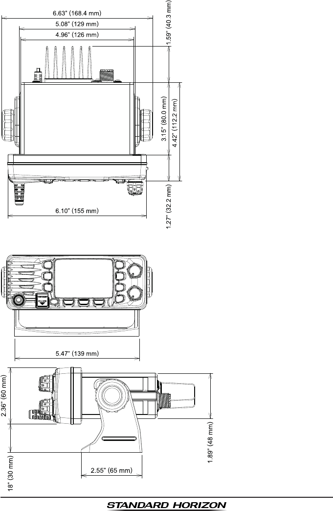
GX1300Page 112
14.4 GX1300 DIMENSIONS

Page 113GX1300
15 FCC RADIO LICENSE INFORMATION
Standard Horizon radios comply with the Federal Communication Commis-
sion (FCC) requirements that regulate the Maritime Radio Service.
15.1 STATION LICENSE
An FCC ship station license is no longer required for any vessel traveling in
U.S. waters (except Hawaii) which is under 20 meters in length. However,
any vessel required to carry a marine radio on an international voyage,
carrying a HF single side band radiotelephone or marine satellite terminal is
required to have a ship station license. FCC license forms, including appli-
cations for ship (605) and land station licenses can be downloaded via the
Internet at http://www.fcc.gov/Forms/Form605/605.html. To obtain a form
from the FCC, call (888) 225-5322.
15.2 RADIO CALL SIGN
Currently the FCC does not require recreational boaters to have a Ship
Radio Station License. The USCG recommends the boats registration
number and the state to be used when calling another vessel.
15.3 CANADIAN SHIP STATION LICENSING
You may need a license when traveling in Canada. If you do need a license
contact their nearest eld ofce or regional ofce or write:
Industry Canada
Radio Regulatory Branch
Attn: DOSP
300 Slater Street
Ottawa, Ontario
Canada, KIA 0C8
15.4 FCC / INDUSTRY CANADA INFORMATION
The following data pertaining to the transceiver is necessary to ll out the
license application.
Type Acceptance .......................................................................... FCC Part 80
Output Power.................................................1 Watt (low) and 25 Watts (high)
Emission ..........................................................................16K0G3E, 16K0G2B
Frequency Range ......................................................156.025 to 163.275 MHz
FCC Type Number .................................................................... K6630583X3D
Industry Canada Type Approval ............................................ 511B-30583X3D

GX1300Page 114
16 FCC NOTICE
NOTICE
Unauthorized changes or modifications to this equipment may void
compliance with FCC Rules. Any change or modication must be ap-
proved in writing by STANDARD HORIZON.
NOTICE
This equipment has been tested and found to comply with the limits
for a Class B digital device, pursuant to Part 15 of the FCC Rules.
These limits are designed to provide reasonable protection against
harmful interference in a residential installation. This equipment
generates, uses and can radiate radio frequency energy and, if not
installed and used in accordance with the instructions, may cause
harmful interference to radio communications. However, there is no
guarantee that interference will not occur in a particular installation. If
this equipment does cause harmful interference to radio or television
reception, which can be determined by turning the equipment off and
on, the user is encouraged to try to correct the interference by one or
more of the following measures:
Reorient or relocate the receiving antenna.
Increase the separation between the equipment and receiver.
Connect the equipment into an outlet on a circuit different from
that to which the receiver is connected.
Consult the dealer or an experienced radio/TV technician for
help.

Page 115GX1300
THIS DEVICE COMPLIES WITH PART 15 OF THE FCC RULES. OPERATION IS
SUBJECT TO THE FOLLOWING TWO CONDITIONS: (1) THIS DEVICE MAY NOT
CAUSE HARMFUL INTERFERENCE, AND (2) THIS DEVICE MUST ACCEPT ANY
INTERFERENCE RECEIVED, INCLUDING INTERFERENCE THAT MAY CAUSE
UNDESIRED OPERATION.
Changes or modications to this device not expressly approved by YAESU U.S.A.
could void the User’s authorization to operate this device.
This device complies with Industry Canada license-exempt RSS standard(s).
Operation is subject to the following two conditions: (1) this device may not cause
interference, and (2) this device must accept any interference, including interference
that may cause undesired operation of the device.
Le présent appareil est conforme aux CNR d’Industrie Canada applicables aux
appareils radio exempts de licence. L’exploitation est autorisée aux deux conditions
suivantes : (1) l’appareil ne doit pas produire de brouillage, et (2) l’utilisateur de
l’appareil doit accepter tout brouillage radioélectrique subi, même si le brouillage
est susceptible d’en compromettre le fonctionnement.
Under Industry Canada regulations, this radio transmitter may only operate using
an antenna of a type and maximum (or lesser) gain approved for the transmitter by
Industry Canada. To reduce potential radio interference to other users, the antenna
type and its gain should be so chosen that the equivalent isotropically radiated power
(e.i.r.p.) is not more than that necessary for successful communication.
Conformément à la réglementation d’Industrie Canada, le présent émetteur radio
peut fonctionner avec une antenne d’un type et d’un gain maximal (ou inférieur)
approuvé pour l’émetteur par Industrie Canada. Dans le but de réduire les risques
de brouillage radioélectrique à l’intention des autres utilisateurs, il faut choisir le
type d’antenne et son gain de sorte que la puissance isotrope rayonnée quivalente
(p.i.r.e.) ne dépassepas l’intensité nécessaire à l’établissement d’une communication
satisfaisante.
This radio transmitter (identify the device by certication number, or model number
if Category II) has been approved by Industry Canada to operate with the antenna
types listed below with the maximum permissible gain and required antenna
impedance for each antenna type indicated. Antenna types not included in this list,
having a gain greater than the maximum gain indicated for that type, are strictly
prohibited for use with this device.
Le présent émetteur radio (identier le dispositif par son numéro de certication ou
son numéro de modèle s’il fait partie du matériel de catégorie I) a été approuvé par
Industrie Canada pour fonctionner avec les types d’antenne énumérés ci-dessous
et ayant un gain admissible maximal et l’impédance requise pour chaque type
d’antenne. Les types d’antenne non inclus dans cette liste, ou dont le gain est
supérieur au gain maximal indiqué, sont strictement interdits pour l’exploitation de
l’émetteur. l’établissement d’une communication satisfaisante.

GX1300Page 116
Copyright 2014
YAESU MUSEN CO., LTD.
All rights reserved.
No portion of this manual
may be reproduced without
the permission of
YAESU MUSEN CO., LTD.
Printed in China
YAESU MUSEN CO., LTD.
Tennozu Parkside Building
2-5-8 Higashi-Shinagawa, Shinagawa-ku, Tokyo 140-0002 Japan
YAESU USA
6125 Phyllis Drive, Cypress, CA 90630, U.S.A.
YAESU UK
Unit 12, Sun Valley Business Park, Winnall Close
Winchester, Hampshire, SO23 0LB, U.K.