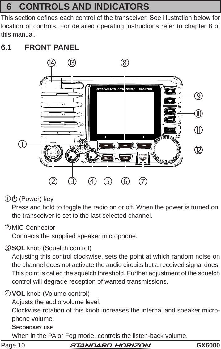
Yaesu Musen 30593X3D MOBILE MARINE TRANSCEIVER User Manual GX6000 Owner s Manual
Yaesu Musen Co., Ltd. MOBILE MARINE TRANSCEIVER GX6000 Owner s Manual
UserManual.wiki
>
Yaesu Musen
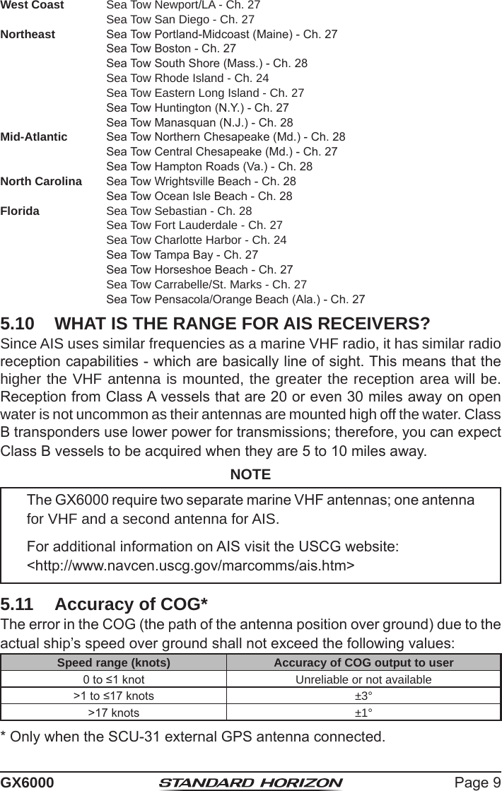
>
30593X3D User Manual
>
OM User Manual 1
Contents
1.
OM User Manual 1
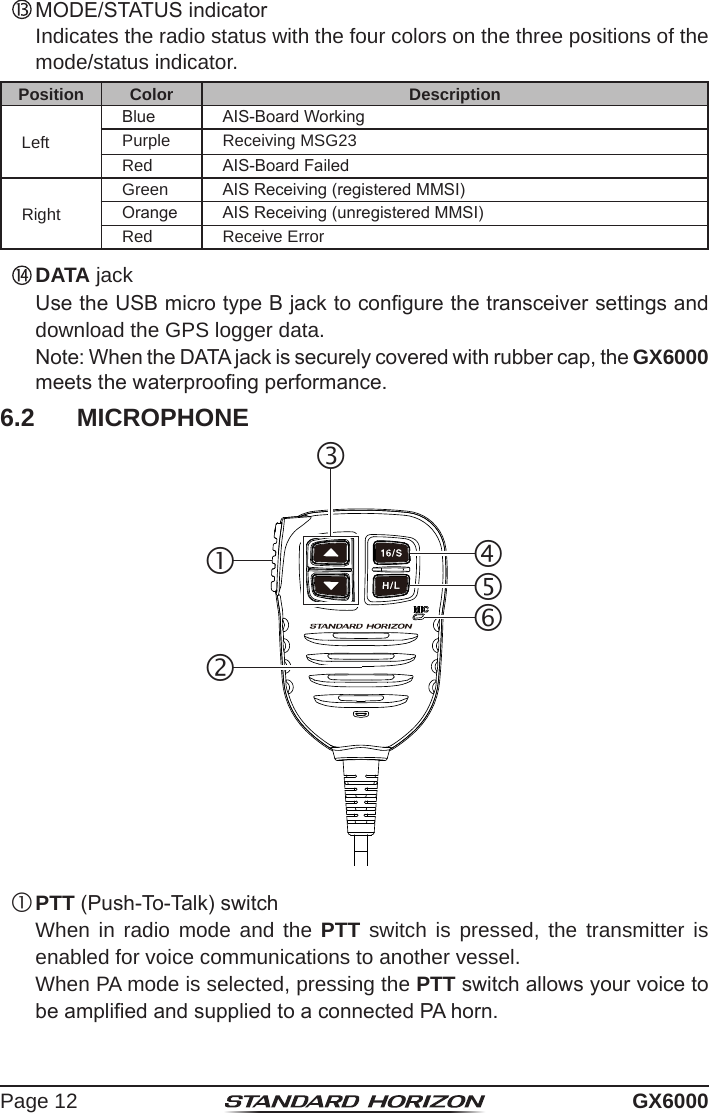
2.
OM User Manual 2
3.
OM User Manual 3
4.
OM User Manual 4
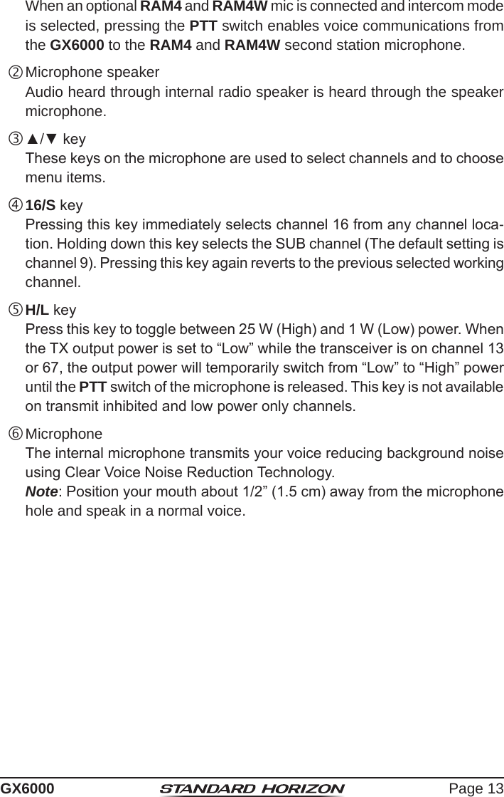
5.
OM User Manual 5
6.
OM User Manual 6
7.
OM User Manual 7
8.
OM User Manual 8
9.
OM User Manual 9
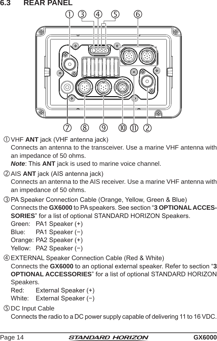
10.
OM User Manual 10
OM User Manual 1
Navigation menu
Upload a User Manual
Namespaces
Wiki Guide
HTML
PDF
Info
Views
User Manual
Discussion / Help
Navigation
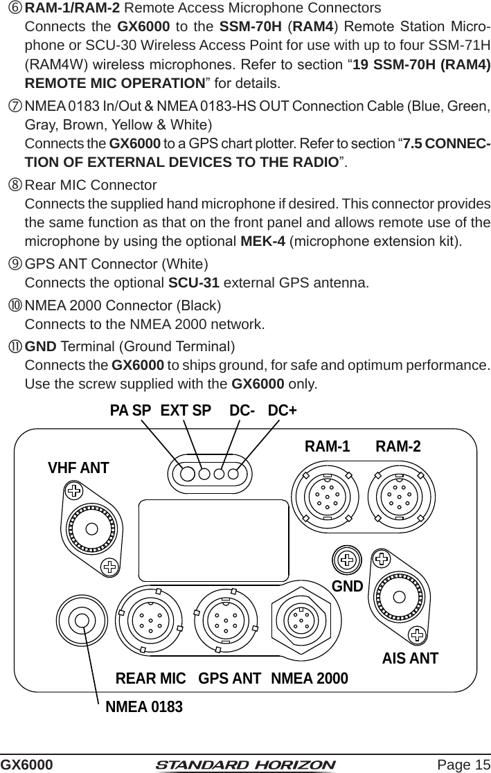
![Page 3GX60001 GENERAL INFORMATIONThe STANDARD HORIZON GX6000 Marine VHF/FM Marine transceiver is designed to be used in USA, International, and Canadian Marine bands. The GX6000 can be operated from 11 to 16 VDC and has a switchable RF output power of 1 watt or 25 watts.The GX6000 integrates a dual channel AIS (Automatic Identication System) receiver to display class A and B AIS vessel information (MMSI, Call Sign, Ship Name, BRG, DST, SOG and COG) directly on the LCD display. The GX6000 has a separate AIS antenna connection to ensure that your will be able to receive AIS signals while transmitting VHF communications. The GX6000 is also capable of entering and saving up to 250 waypoints, which may be selected and navigated to by using a unique navigation compass display. The GX6000 allows you to contact an AIS ship directly using DSC, show your vessels position in relation to AIS targets and alert you when an AIS ship may be approaching too close to your location via the Closest Point of Approach (CPA) Alarm or Time to Closest Point of Approach (TCPA) Alarm.The GX6000 is capable of DSC (Digital Selective Calling) ITU-R M.493 Class D operation. Class D operation allows continuous receiving of Digital Selective Calling functions on channel 70 even if the radio is receiving a call. The GX6000 operates on all currently-allocated marine channels which are switchable for use with USA, International, or Canadian regulations. Emergency channel 16 can be immediately selected from any channel by pressing the red 16/S key. NOAA weather channel can also be accessed immediately by pressing the [WX] soft key.Other features of the GX6000 includes: Noise canceling function for transmit and receive audio, NMEA 2000 compatibility, high expandability, integrated voice recorder to play back up to two minutes of RX receive audio, speaker microphone, dual zone 25 W PA/Loud hailer with preprogrammed fog signals and listen back, capable of being connected to two optional wired RAM4 or one wired RAM4 and four Wireless RAM4W*1 remote access microphones, allowing full control of all VHF, DSC and hailer functions remotely including an intercom feature allowing you to communicate between the radio, RAM4 and Wireless RAM4W microphones, scanning, priority scanning, submersible speaker microphone, high and low voltage warning, and GPS repeatability. (*1 requires SCU-30 Wireless Access Port)](https://usermanual.wiki/Yaesu-Musen/30593X3D.OM-User-Manual-1/User-Guide-3702462-Page-5.png)


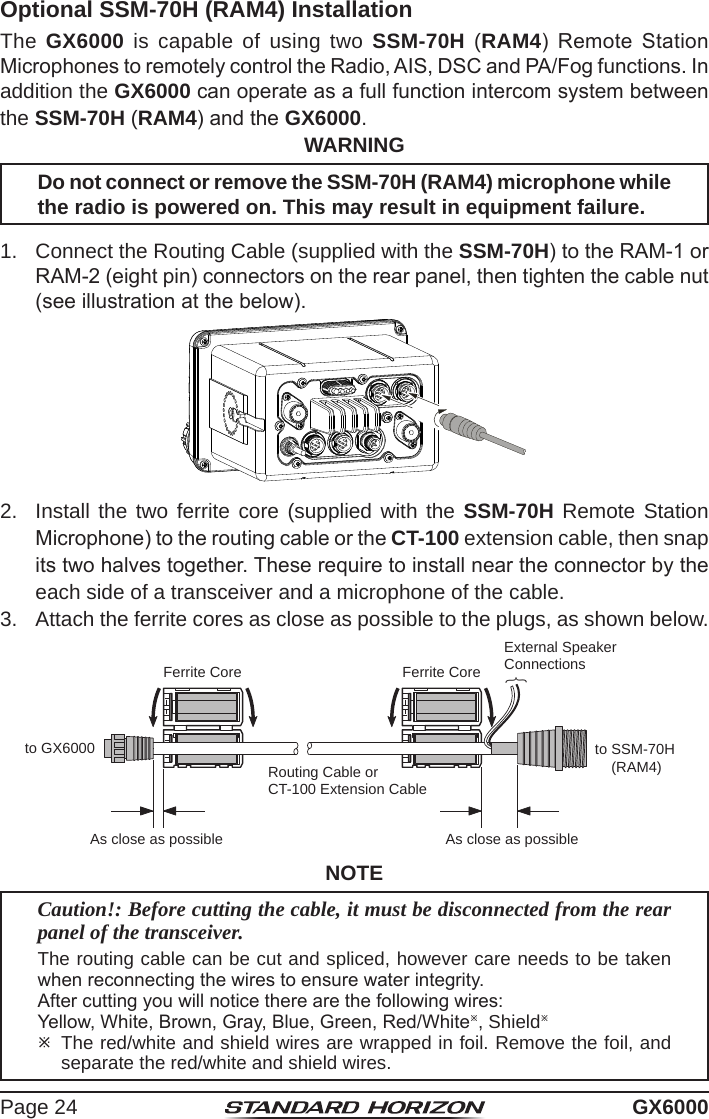
![Page 25GX60004. Finally, wind some plastic tape around each ferrite core, to prevent vibration from causing the two halves to split apart.WallGasketMounting BracketRouting CableCapNutExternal Speaker ConnectionsFerrite Core5. Referring to illustration right, make a 1.2” (30 mm) hole in the wall, then insert the extension cable into this hole. Connect the gasket and mount base to the extension cable connector using the nut.6. Drill the four screw holes (approx. 2 mm) on the wall, then install the mounting base to the wall using four screws.7. Put the rubber cap on to the nut. The installation is now complete.WARNINGIt is not recommended to plug or unplug the SSM-70H (RAM4) Remote Station Microphone into the routing cable while the radio is powered on. Connecting an External Speaker to the RAM4 Mic CableIn noisy locations and MLS-300/MLS-310 optional external speaker may be connected to the white speaker wires on the RAM4 routing cable. The RAM4 can drive the internal speaker or the external speaker one at a time. When connecting an external speaker, follow the procedure below to turn off the RAM4 audio and enable the external speaker wires on the RAM4 routing cable.1. On the RAM4 mic, press the MENU key to display “MENU”.cc 2. Rotate the DIAL/ENT knob to select “SETUP”, then press the [SELECT] soft key.3. Rotate the DIAL/ENT knob to select “CONFIGURA-TION”, then press the [SELECT] soft key.](https://usermanual.wiki/Yaesu-Musen/30593X3D.OM-User-Manual-1/User-Guide-3702462-Page-27.png)
![Page 26 GX60004. Rotate the DIAL/ENT knob to select “SPEAKER SELECT”, then press the [SELECT] soft key.5. Rotate the DIAL/ENT knob to select “INTERNAL” or “EXTERNAL”, then press the [SELECT] soft key.6. Press the CLEAR/ key to return to radio operation.7.6 INITIAL SETUP REQUIRED WHEN TURNING ON THE POWER FOR THE FIRST TIME7.6.1 Maritime Mobile Service Identity (MMSI)What is an MMSI?An MMSI is a nine digit number used on marine transceivers capable of using Digital Selective Calling (DSC) and Automatic Identication System (AIS) signal transmission. This number is used like a telephone number to selectively call other vessels.THIS NUMBER MUST BE PROGRAMMED INTO THE RADIO TO OPERATE DSC FUNCTIONS.How can I obtain an MMSI assignment?In the USA, visit the following websites to register:http://www.boatus.com/mmsi/https://www.seatow.com/tools-and-education/mmsihttp://wireless.fcc.gov/services/index.htm?job=licensing&id=ship_stationsIn Canada, visithttp://www.ic.gc.ca/epic/site/smt-gst.nsf/en/sf01032e.htmlWARNINGThe MMSI can be inputted only once, please be careful not to input the incorrect MMSI number. If you need to change the MMSI number after it has been entered, the radio will have to be returned to Factory Service. Refer to the section “21.2 FACTORY SERVICE”.](https://usermanual.wiki/Yaesu-Musen/30593X3D.OM-User-Manual-1/User-Guide-3702462-Page-28.png)
![Page 27GX6000Programming the MMSI1. Press the MENU key to display “MENU”. 2. Rotate the DIAL/ENT knob to select “MMSI/POS INFO”, then press the [SELECT] soft key. (To cancel, press the [BACK] soft key.)To view your MMSI to ensure it is correct, perform steps 1 to 2.3. Press the [MMSI] soft key. The [MMSI] soft key is displayed which has not yet set the MMSI.In the case of the GX6000 which has completed the MMSI setting, you can only check the MMSI on this screen.*********4. Rotate the DIAL/ENT knob to select the rst number of your MMSI, then press the [SELECT] soft key to step to the next number.5. Repeat step 4 to set your MMSI number (9 digits).6. If a mistake was made entering in the MMSI number, rotate the DIAL/ENT knob to select “←” or “→”, press the [SELECT] soft key until the wrong character is selected, then perform step 4.7. When nished programming the MMSI number, press the [FINISH] soft key. The radio will ask you to input the MMSI number again. Perform steps 4 through 6 above.8. After the second number has been input, press the [FINISH] soft key to store the MMSI.9. Press the [OK] soft key to return to radio operation.NOTETo view your MMSI after programming to ensure it is correct, perform steps 1 to 2. Look that the MMSI number shown on the display is correct.](https://usermanual.wiki/Yaesu-Musen/30593X3D.OM-User-Manual-1/User-Guide-3702462-Page-29.png)
![Page 28 GX60007.7 CHECKING GPS SIGNAL (GPS STATUS DISPLAY)When the GX6000 receives the GPS signal from the optional SCU-31, a small satellite icon “ ”* will appear on the display and your current location (latitude/longitude) is shown on the display. (*When the GPS signal receiving from the NMEA 2000 or NEMA-0183, a “2K” (NMEA 2000) icon or “I/O” (NMEA-0183) icon will appear on the display.)NOTEIf there is a problem with the NMEA connection between the radio and the GPS, the GPS icon will blink continuously until the connection is corrected.The GX6000 has a GPS status display which shows the satellites currently being received, along with a graphi-cal (bar-graph) representation of the relative signal strengths from the satellites.(GPS StatuS diSPlay mode)NOTEFor the GX6000 to properly show the GPS status page when an external GPS antenna or a chart plotter is connected it must be setup to output GSA and GSV NMEA 0183 sentences. When using the equipment of NMEA 2000, it must be able to output PGN No.129540 (GNSS Sats in View). 1. Press the MENU key to display “MENU”.2. Rotate the DIAL/ENT knob to select “GPS”, then press the [SELECT] soft key.3. Rotate the DIAL/ENT knob to select “GPS STATUS”, then press the [ENTER] soft key to display the GPS status currently being received.4. Press the CLEAR key to return to radio operation.](https://usermanual.wiki/Yaesu-Musen/30593X3D.OM-User-Manual-1/User-Guide-3702462-Page-30.png)
![Page 29GX60007.8 GPS CONFIGURATION7.8.1 Changing the GPS TimeThe GX6000 shows GPS satellite time or UTC (Universal Time Coordinated) time in factory default. A time offset is needed to show the local time in your area. The time offset must be changed in order for the radio to display the current time in your area.1. Press the MENU key to display “MENU”.cc 2. Rotate the DIAL/ENT knob to select “SETUP”, then press the [SELECT] soft key.3. Rotate the DIAL/ENT knob to select “GPS SETUP”, then press the [SELECT] soft key.4. Rotate the DIAL/ENT knob to select “TIME OFFSET”, then press the [SELECT] soft key.5. Rotate the DIAL/ENT knob to select time offset of your location. See illustration above to nd your offset time. If “00:00” is assigned, the time is the same as UTC or GPS satellite time.6. Press the [ENTER] soft key to store the time offset.7. Press the CLEAR key to return to radio operation.7.8.2 Changing the Time AreaThis menu selection allows the radio to show UTC time or local time with offset.1. Press the MENU key to display “MENU”.cc 2. Rotate the DIAL/ENT knob to select “SETUP”, then press the [SELECT] soft key.3. Rotate the DIAL/ENT knob to select “GPS SETUP”, then press the [SELECT] soft key.](https://usermanual.wiki/Yaesu-Musen/30593X3D.OM-User-Manual-1/User-Guide-3702462-Page-31.png)
![Page 30 GX60004. Rotate the DIAL/ENT knob to select “TIME AREA”, then press the [SELECT] soft key.5. Rotate the DIAL/ENT knob to select “UTC” or “LOCAL”.6. Press the [ENTER] soft key to store the selected setting.7. Press the CLEAR key to return to radio operation.7.8.3 Changing the Time FormatThis menu selection allows the radio to setup to show time in 12-hour or 24-hour format.1. Press the MENU key to display “MENU”.cc 2. Rotate the DIAL/ENT knob to select “SETUP”, then press the [SELECT] soft key.3. Rotate the DIAL/ENT knob to select “GPS SETUP”, then press the [SELECT] soft key.4. Rotate the DIAL/ENT knob to select “TIME FORMAT”, then press the [SELECT] soft key.5. Rotate the DIAL/ENT knob to select “24hour” or “12hour”.6. Press the [ENTER] soft key to store the selected setting.7. Press the CLEAR key to return to radio operation.](https://usermanual.wiki/Yaesu-Musen/30593X3D.OM-User-Manual-1/User-Guide-3702462-Page-32.png)