Yaesu Musen 30623X30 PORTABLE MARINE TRANSCEIVER User Manual HX40 Operating Manual
Yaesu Musen Co., Ltd. PORTABLE MARINE TRANSCEIVER HX40 Operating Manual
Operating Manual
HX40
VHF FM Marine Transceiver
Owner’s Manual
ApplicationforFCC/IC
FCCID:K6630623X30IC:511B-30623X30

1. GENERAL INFORMATION .................................. 1
1.1 INTRODUCTION ............................................ 1
2. SAFETY PRECAUTIONS .................................... 2
3. ABOUT THIS RADIO ........................................... 4
3.1 ABOUT THE VHF MARINE BAND ................. 4
3.2 ABOUT WATER PROTECTION ..................... 4
3.3 DISTRESS AND HAILING (CHANNEL 16) .... 4
3.4
CALLING ANOTHER VESSEL (CHANNEL 16 OR 9)
.. 5
3.5 BRIDGE CHANNELS 13 AND 67 .................. 6
3.6 SIMPLEX/DUPLEX CHANNEL USE .............. 6
3.7 AUTOMATED RADIO CHECK SERVICE ...... 7
4. ACCESSORIES ................................................... 8
4.1 PACKING LIST ............................................... 8
4.2 OPTIONS ....................................................... 8
5. GETTING STARTED ............................................ 9
5.1 RADIO CARE ................................................ 9
5.2 BATTERIES AND CHARGERS ......................9
5.2.1 BATTERY SAFETY ............................... 9
5.2.2 BATTERY CHARGING ........................ 10
5.3 BELT CLIP INSTALLATION / REMOVAL ..... 11
6. CONTROLS AND INDICATORS ........................ 12
6.1 CONTROLS AND SWITCHES ..................... 12
6.2 LCD INDICATORS ....................................... 14
7. BASIC OPERATION .......................................... 16
7.1 PROHIBITED COMMUNICATIONS ............. 16
7.2 INITIAL SETUP ............................................ 16
7.3 RECEPTION ................................................ 16
7.4 TRANSMISSION .......................................... 16
7.4.1 TRANSMIT POWER ........................... 17
7.4.2
TRANSMIT TIME - OUT TIMER (TOT)
... 17
7.5 USA, CANADIAN, AND
INTERNATIONAL CHANNELS .... 17
7.6 KEYPAD LOCKING ...................................... 18
7.7 NOAA WEATHER CHANNELS .................... 18
7.7.1 NOAA WEATHER ALERT ................... 18
7.7.2 NOAA WEATHER ALERT TESTING ...19
7.8
PRESET CHANNELS: INSTANT ACCESS
... 20
7.8.1 PROGRAMMING PRESET
CHANNEL BANKS .... 20
7.8.2 OPERATION on a Preset Channel ...... 20
7.8.3 Deleting a Preset Channel .................. 21
7.9 SCANNING .................................................. 22
7.9.1 PROGRAMMING SCAN MEMORY .... 22
7.9.2 SELECTING SCAN TYPE ................... 22
7.9.3 SCANNING OPERATION ................... 23
7.10
MULTI WATCH (TO PRIORITY CHANNEL)
... 24
7.10.1
Setting up the Multi Watch Operation
... 24
7.10.2 Starting the Dual Watch .................... 25
7.10.3 Starting the Triple Watch ................... 25
7.11 Listening to the FM Radio .......................... 26
FM broadcast Frequency sweep operation
... 26
Store the FM frequency ................................ 26
Memory Frequency Recall ........................... 27
7.12 Soft Keys .................................................... 27
Key Assignment............................................ 27
Key Timer ..................................................... 28
8. MENU (“SETUP”) .............................................. 29
CHANNEL SETUP ............................................. 29
CHANNEL GROUP ...................................... 29
WEATHER ALERT ....................................... 29
SCAN MEMORY .......................................... 29
SCAN TYPE ................................................. 29
SCAN RESUME ........................................... 30
MULTI WATCH ............................................. 30
PRIORITY CH .............................................. 30
SUB CH ........................................................ 30
FM SETUP ......................................................... 31
ADD .............................................................. 31
EDIT ............................................................. 32
DELETE ....................................................... 32
CONFIG ............................................................. 32
KEY BEEP .................................................... 32
BATTERY SAVE ........................................... 33
KEY SETUP ................................................. 33
BACKLIT LEVEL .......................................... 33
BACKLIT TIMER .......................................... 33
CONTRAST .................................................. 34
RESET ......................................................... 34
ABOUT... ............................................................ 34
9. MAINTENANCE ................................................. 35
9.1 GENERAL .................................................... 35
9.2 FACTORY SERVICE .................................... 35
9.3 TROUBLESHOOTING CHART .................... 35
10. VHF MARINE CHANNEL ASSIGNMENTS ..... 36
11. WARRANTY ..................................................... 42
Marine Products Limited Warranty ..................... 42
12. SPECIFICATIONS ............................................ 45
11.1 GENERAL .................................................. 45
11.2 TRANSMITTER .......................................... 45
11.3 RECEIVER ................................................. 45
11.4 FM BROADCAST RECEIVER.................... 45
13. FCC AND CANADA RADIO LICENSE
INFORMATION ...... 46
MARITIME STATION LICENSE ......................... 46
MARINE RADIO CALL SIGN ............................. 46
CANADIAN SHIP STATION LICENSING ........... 46
FCC / ISED INFORMATION .............................. 46
14. RF EXPOSURE SAFETY STATEMENT .......... 47
SAFETY INFORMATION ................................... 47
CONSIGNES DE SECURITE ............................ 47
15. FCC NOTICE .................................................... 47
TABLE OF CONTENTS
ApplicationforFCC/IC
FCCID:K6630623X30IC:511B-30623X30

Page 1
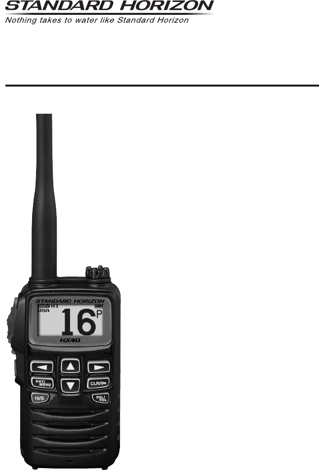
HX40
1. GENERAL INFORMATION
1.1 INTRODUCTION
Congratulations on your purchase of the HX40! Whether this is your
first portable marine VHF transceiver, or if you have other STANDARD
HORIZON equipment, the STANDARD HORIZON organization is commit-
ted to ensuring your enjoyment of this high-performance transceiver, which
should provide you with many years of satisfying communications even in
the harshest of environments. STANDARD HORIZON technical support
personnel stand behind every product sold, and we invite you to contact us
should you require technical advice or assistance by calling (800)767-2450
Monday through Friday 8AM to 5PM Pacic time.
The HX40 is a Submersible 6-Watt portable two-way marine transceiver.
The transceiver has all allocated USA, International, or Canadian channels.
It has emergency channel 16 which can be immediately selected from any
channel by pressing the [16/S] key.
The HX40 includes the following features: Memory Scanning, Priority Scan-
ning, Dual and Triple watch, NOAA Weather Alert, easy-to-read large LCD
display, Battery Life display on the LCD, and a transmit Time-Out Timer
(TOT).
The HX40 transmitter provides a full 6 Watts of transmit power which is also
to selectable to 1 Watt to assist the user in ensuring maximum battery life.
We appreciate your purchase of the HX40, and encourage you to read this
manual thoroughly, so as to learn and fully understand the capabilities of the
HX40.
ApplicationforFCC/IC
FCCID:K6630623X30IC:511B-30623X30
HX40
Page 2
2. SAFETY PRECAUTIONS
Be sure to read the safety precautions, and use this product safely.
Yaesu is not liable for any failures or problems caused by the use or misuse
of this product by the purchaser or any third party. Also, Yaesu is not liable
for damages caused through the use of this product by the purchaser or any
third party, except in cases where ordered to pay damages under the laws.
Types and meanings of the marks
DANGER This mark indicates an imminently hazardous situation, which, if not avoided, could
result in death or serious injury.
WARNING This mark indicates a potentially hazardous situation, which, if not avoided, could
result in death or serious injury.
CAUTION This mark indicates a potentially hazardous situation, which, if not avoided, may result
in minor or moderate injury or only property damage.
Types and meanings of symbols
These symbols signify prohibited actions, which must not be done to use this product safely.
For example: indicates that the product should not be disassembled.
These symbols signify required actions, which must be done to use this product safely. For example:
indicates that the power plug should be disconnected.
DANGER
Do not operate the device when flammable
gas is generated.
Doing so may result in fire and explosion.
Do not transmit with this device in a crowded
place for the safety of persons using a medi-
cal device such as a cardiac pacemaker.
The radio wave emitted from this product can
cause the medical device to malfunction and re-
sult in an accident.
Do not touch any liquid leaking from the liquid
display with your bare hands.
There is a risk of chemical burns occurring when
the liquid comes into contact with the skin or gets
into the eyes. In this case, seek medical treatment
immediately.
Do not touch any material leaking from the bat-
tery pack with bare hands.
The chemical that has stuck to your skin or en-
tered your eye can cause chemical burns. In such
a case, consult the doctor immediately.
Do not solder or short-circuit the terminals of
the battery pack.
A fire, leak, overheating, explosion, or ignition may
result.
Do not carry the battery pack together with a neck-
lace, hairpin, or small metal objects. A short circuit
can result.
WARNING
Do not power this transceiver with a voltage
other than the specified power supply voltage.
A fire, electric shock, or damage may result.
Do not make very long transmissions.
The main body of the transceiver may overheat,
resulting component failure or operator burns.
Do not disassemble or make any alteration to
this product.
An injury, electric shock, or failure may result.
Never touch the antenna during transmission.
This may result in injury, electric shock and equip-
ment failure.
Do not handle the battery pack or charger with
wet hands. Do not insert or remove the power
plug with wet hands.
An injury, leak, fire, or failure may result.
If smoke or a strange odor is emitted from the
main body, battery pack, or battery charger,
immediately turn the transceiver off; remove
the battery pack.
A fire, chemical leak, overheating, component
damage, ignition, or failure may result. Please
contact the dealer from which you purchased this
product.
ApplicationforFCC/IC
FCCID:K6630623X30IC:511B-30623X30
Page 3
HX40
CAUTION
Do not place the transceiver on an unsteady
or sloping surface, or in a location with ex-
treme vibration.
The transceiver may fall or drop, resulting in fire,
injury and equipment damage.
Stay as far away from the antenna as possible
during transmission.
Long-term exposure to electromagnetic radiation
may have a negative effect on the human body.
Do not dangle or throw the transceiver by
holding its antenna.
This may injure others and may also result in
damage and failure of the transceiver.
Do not wipe the case using thinner and ben-
zene etc.
Use only a soft, dry cloth to wipe stains from the
case.
Keep this product out of the reach of children.
Injury to the child, or damage to the transceiver
may result.
Do not use any products other than the speci-
fied options and accessories.
Failure or miss operation may result.
If the transceiver will not be used for an ex-
tended period, turn it OFF and remove the bat-
tery pack for safety.
Do not throw the transceiver, or subject it to
strong impact forces.
Physical abuse may result in component damage
and equipment failure.
Keep magnetic cards and videotapes away
from the transceiver.
The data recorded on cash cards or videotapes
may be erased.
Do not use the transceiver in a crowded place.
The antenna may strike others and result in an
injury.
Install the hand strap and belt clip securely.
Improper installation may cause the transceiver to
fall or drop, resulting in an injury or damage.
Before discarding a depleted battery pack, af-
fix tape or insulating covering to its terminals.
ApplicationforFCC/IC
FCCID:K6630623X30IC:511B-30623X30

HX40
Page 4
3. ABOUT THIS RADIO
3.1 ABOUT THE VHF MARINE BAND
The radio frequencies used in the VHF marine band lie between 156 and
158 MHz with NOAA Weather stations available between 161 and 163 MHz.
The marine VHF band provides communications over distances that are
essentially “Line of sight” Actual transmission range depends much more
on antenna type, gain and height than on the power output of the transmit-
ter. On a xed mount 25 W radio transmission expected distances can be
greater than 15 miles, for a portable 5 W radio transmission the expected
distance can be greater than 5 miles in “Line of sight”.
The user of a Marine VHF radio is subject to severe nes if the radio is used
on land. The reasoning for this is you may be near an inland waterway, or
propagation anomalies may cause your transmission to be heard in a wa-
terway. If this occurs, depending upon the marine VHF channel on which
you are transmitting, you could interfere with a search and rescue case, or
contribute to a collision between passing ships. For VHF Marine channel as-
signments refer to section “10. VHF MARINE CHANNEL ASSIGNMENTS”.
WARNING
This radio is capable of transmitting on Marine VHF radio frequencies.
The FCC allows the use of VHF Marine band on water areas only. Use of
the VHF Marine band when on land is not permitted. If persons use the
VHF Marine Band on land and interfere with other communications, the
FCC will be notied and search for the interference. Responsible parties
found to be transmitting on the VHF Marine Band on land could be ned up
to $10,000 for the rst offense.
3.2 ABOUT WATER PROTECTION
The HX40 is only submersible※ when the MIC/SP cap is installed in the MIC/SP jack.
※IPX7 Specication for submersibility: 3 ft. (1 m) for 30 minutes.
3.3 DISTRESS AND HAILING (CHANNEL 16)
Channel 16 is designated as the Hail and Distress Channel. An emergency may
be dened as a threat to life or property. In such instances, be sure the trans-
ceiver is turned ON, and set to “Channel 16”. Then use the following procedure:
1. Press the PTT (Push-To-Talk) switch and say “Mayday, Mayday, May-
day. This is _____, _____, _____” (your vessel’s name).
2. Then repeat once: “Mayday, _____” (your vessel’s name).
3. Now report your position in latitude/longitude, or by giving a true or mag-
netic bearing (state which) to a well-known landmark such as a naviga-
tion aid or geographic feature such as an island or harbor entry.
4. Explain the nature of your distress (sinking, collision, aground, re, heart
attack, life-threatening injury, etc.).
ApplicationforFCC/IC
FCCID:K6630623X30IC:511B-30623X30

Page 5
HX40
5. State the kind of assistance you desire (pumps, medical aid, etc.).
6. Report the number of persons aboard and condition of any injured.
7. Estimate the present seaworthiness and condition of your vessel.
8. Give your vessel’s description: length, design (power or sail), color and
other distinguishing marks. The total transmission should not exceed 1
minute.
9. End the message by saying “OVER”. Release the PTT switch and listen.
10. If there is no answer, repeat the above procedure. If there is still no re-
sponse, try another channel.
3.4 CALLING ANOTHER VESSEL (CHANNEL 16 OR 9)
Channel 16 may be used for initial contact (hailing) with another vessel.
However, its most important use is for emergency messages. This channel
must be monitored at all times except when actually using another channel.
It is monitored by the U.S. and Canadian Coast Guards and by other ves-
sels. Use of channel 16 for hailing must be limited to initial contact only. Call-
ing should not exceed 30 seconds, but may be repeated 3 times at 2-minute
intervals. In areas of heavy radio trafc, congestion on channel 16 resulting
from its use as a hailing channel can be reduced signicantly in U.S. waters
by using Channel 9 as the initial contact (hailing) channel for non-emergency
communications. Here, also, calling time should not exceed 30 seconds but
may be repeated 3 times at 2-minute intervals.
Prior to making contact with another vessel, refer to the channel charts in this
manual, and select an appropriate channel for communications after initial
contact. For example, Channels 68 and 69 of the U.S. VHF Charts are some
of the channels available to non-commercial (recreational) boaters. Monitor
your desired channel in advance to make sure you will not be interrupting
other trafc, and then go back to either channel 16 or 9 for your initial contact.
When the hailing channel (16 or 9) is clear, state the name of the other ves-
sel you wish to call and then “this is” followed by the name of your vessel
and your Station License (Call Sign). When the other vessel returns your
call, immediately request another channel by saying “go to”, the number of
the other channel, and “over”. Then switch to the new channel. When the
new channel is not busy, call the other vessel.
After a transmission, say “over”, and release the PTT (Push-To-Talk) switch.
When all communication with the other vessel is completed, end the last
transmission by stating your Call Sign and the word “out”. Note that it is not
necessary to state your Call Sign with each transmission, only at the begin-
ning and end of the contact.
Remember to return to Channel 16 when not using another channel. Some
radios automatically monitor Channel 16 even when set to other channels or
when scanning.
ApplicationforFCC/IC
FCCID:K6630623X30IC:511B-30623X30

HX40
Page 6
3.5 BRIDGE CHANNELS 13 AND 67
Channel 13 is used at docks, bridges and by vessels maneuvering in port.
Messages on this channel must concern navigation only, such as meeting
and passing in restricted waters.
Channel 67 is used for navigational trafc between vessels.
By regulation, power is normally limited to 1 Watt on these channels. Your
radio is programmed to automatically reduce power to this limit on these
channels. However, in certain situations it may be necessary to temporarily
use a higher power. See page 14 for means to temporarily override the low-
power limit on these two channels.
3.6 SIMPLEX/DUPLEX CHANNEL USE
Refer to the section “10. VHF MARINE CHANNEL ASSIGNMENTS” for in-
structions on use of simplex and duplex channels.
NOTE
All channels are factory-programmed in accordance with FCC (USA),
ISED (Canada) and International regulations. The mode of operation
cannot be altered from simplex to duplex or vice-versa. Simplex (ship to
ship) or duplex (marine operator) mode is automatically activated, de-
pending on the channel and whether the USA, International or Canadian
operating band is selected.
ApplicationforFCC/IC
FCCID:K6630623X30IC:511B-30623X30

Page 7
HX40
3.7 AUTOMATED RADIO CHECK SERVICE
In areas across the country, Sea Tow offers boaters a way to conduct radio
checks. To use Sea Tow’s free Automated Radio Check service, simply tune
your VHF radio to the appropriate channel for your location and conduct a
radio check as you typically would. Upon releasing your radio’s microphone,
the system will play an automated message and relay your transmission
back to you, thereby letting you know how your signal will sound to other
boaters.
The Automated Radio Check Service is currently available in the areas listed
below.
West Coast
Sea Tow Newport/LA - Ch. 27
Sea Tow San Diego - Ch. 27
Northeast
Sea Tow Portland-Midcoast (Maine) - Ch. 27
Sea Tow Boston - Ch. 27
Sea Tow South Shore (Mass.) - Ch. 28
Sea Tow Rhode Island - Ch. 24
Sea Tow Eastern Long Island - Ch. 27
Sea Tow Huntington (N.Y.) - Ch. 27
Sea Tow Manasquan (N.J.) - Ch. 28
Mid-Atlantic
Sea Tow Northern Chesapeake (Md.) - Ch. 28
Sea Tow Central Chesapeake (Md.) - Ch. 27
Sea Tow Hampton Roads (Va.) - Ch. 28
North Carolina
Sea Tow Wrightsville Beach - Ch. 28
Sea Tow Ocean Isle Beach - Ch. 28
Florida
Sea Tow Sebastian - Ch. 28
Sea Tow Fort Lauderdale - Ch. 27
Sea Tow Charlotte Harbor - Ch. 24
Sea Tow Tampa Bay - Ch. 27
Sea Tow Horseshoe Beach - Ch. 27
Sea Tow Carrabelle/St. Marks - Ch. 27
Sea Tow Pensacola/Orange Beach (Ala.) - Ch. 27
ApplicationforFCC/IC
FCCID:K6630623X30IC:511B-30623X30

HX40
Page 8
4. ACCESSORIES
4.1 PACKING LIST
When the package containing the transceiver is rst opened, please check it
for the following contents:
HX40 Transceiver
CAT460 Antennaø
SAD-23B AC Adaptor for SBH-27 (100-240 VAC, Type-A plug)
E-DC-19A DC Cable with 12 V Cigarette Lighter Plug
SBH-27 Charger Cradle
SHB-19 Belt Clip
Hand Strap
Owner’s Manual
ø Antenna gain: -1.5 dBi, Impedance: 50 ohm
4.2 OPTIONS
SAD-23B/C/Uø AC Adaptor for SBH-27
SSM-14A Submersible Speaker / Microphone with Earphone Jack
SEP-10A Earphone for SSM-14A
MH-73A4B Submersible Speaker / Microphone
SSM-64A VOX Headset
SSM-55A Earpiece / Microphone
CN-3 Radio-to-Ship’s-Antenna Adapter
SCH-11 Belt Clip Hanger
SCH-29 Floating Jacket
“B” sufx is for use with 100-240 VAC (Type-A plug), “C” sufx is for use
with 100-240 VAC (Type-C plug), and “U” sufx is for use with 100-240 VAC
(Type-BF plug).
Note: Before operating the HX40 for the rst time, it is recommended that
the battery be charged. Please see section “5.2.2 BATTERY CHARGING”
for details.
ApplicationforFCC/IC
FCCID:K6630623X30IC:511B-30623X30

Page 9
HX40
5. GETTING STARTED
5.1 RADIO CARE
After using the HX40 in a salt water environment, it is recommended to clean
the radio with fresh water by rinsing the radio under a sink faucet or by dunk-
ing the radio in a bucket of fresh water. After washing, use a soft cloth and
thoroughly dry all parts of the radio. This is to keep the rubber switches and
speaker grill clean and in top operating condition.
5.2 BATTERIES AND CHARGERS
If the radio has never been used, or its charge is depleted, it may be charged
by connecting the SBH-27 Charger Cradle with the SAD-23B AC Adapter,
see section “5.2.2 BATTERY CHARGING”. If 12V DC power is available, the
supplied E-DC-19A DC Cable with 12 V Cigarette Lighter Plug may be used
for charging the battery. The SAD-23B and E-DC-19A will charge a com-
pletely discharged built-in battery in approximately 3 hours.
CAUTION
To avoid risk of explosion and injury, the built-in battery pack should only be
charged or recharged in non-hazardous environments.
5.2.1 BATTERY SAFETY
The built-in battery of this transceiver contains Li-ion batteries. This type
of battery stores a charge powerful enough to be dangerous if misused or
abused, especially when removed from the transceiver. Please observe the
following precautions:
DO NOT SHORT BATTERY PACK TERMINALS: Shorting the terminals
that power the transceiver can cause sparks, severe overheating, burns, and
battery cell damage. If the short is of sufcient duration, it is possible to melt
battery components. Do not place a loose battery pack on or near metal sur-
faces or objects such as paper clips, keys, tools, etc. When the battery pack
is installed on the transceiver, the terminals that transfer current to the trans-
ceiver are not exposed. The terminals that are exposed on the battery pack
when it is mounted on the transceiver are charging terminals only and do not
constitute a hazard.
DO NOT INCINERATE: Do not dispose of any battery in a re or incinerator.
The heat of re may cause battery cells to explode and/or release danger-
ous gases.
Battery Maintenance
For safe and proper battery use, please observe the following:
The built-in battery should be charged only in non-hazardous environ-
ments.
ApplicationforFCC/IC
FCCID:K6630623X30IC:511B-30623X30
HX40
Page 10
Use only STANDARD HORIZON approved batteries.
Do not exceed the specied temperature limits.
Do not reverse the charge polarity. Use only the proper charger. If this is
tampered with or another charger is used, permanent damage may re-
sult.
Use only a STANDARD HORIZON approved charger. The use of any
other charger may cause permanent damage to the battery.
Follow charging instructions provided with the chargers.
Battery Recycling
DO NOT PLACE USED BATTERIES IN THE REGULAR TRASH!
LI-ION BATTERIES MUST BE COLLECTED, RECYCLED
OR DISPOSED OF IN AN ENVIRONMENTALLY SOUND
MANNER.
Incinerating Li-ion batteries, placing them in the land ll, or mixing them with
the municipal solid waste collection, is PROHIBITED BY LAW in most areas.
Return batteries to an approved Li-ion battery recycler. This may be avail-
able you purchased the battery.
Contact your local waste management ofcials for other information regard-
ing the environmentally sound collection, recycling and disposal of Li-ion
batteries.
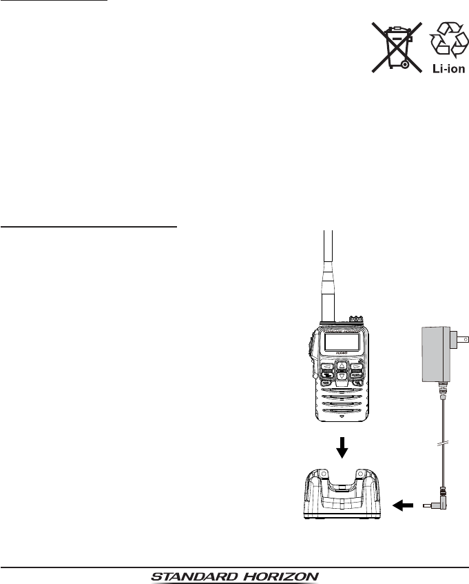
5.2.2 BATTERY CHARGING
1. Turn the transceiver OFF.
2.
Insert the DC plug from the SAD-23B into the
DC jack at the bottom of the SBH-27, then
plug the SAD-23B into the AC line outlet.
3. Place the HX40 into the SBH-27; the anten-
na should be at the left side when viewing
the charger from the front.
4. When the HX40 is inserted correctly, the
HX40’s LCD display will show the battery
charging icon. A fully-discharged pack will
be charged completely in approximately 3
hours.
5. When charging is completed, the battery
charging icon will disappear.
6. Disconnect the Charge Cable from the
HX40, then unplug the SAD-23B from the
AC line outlet.
ApplicationforFCC/IC
FCCID:K6630623X30IC:511B-30623X30
Page 11
HX40
CAUTION
The SAD-23 and SBH-27 are NOT designed to be waterproof. Do not at-
tempt to charge in water hazardous locations.
NOTE
The SAD-23B is only designed for the charging of the HX40’s built-
in battery, and is not suitable for other purposes. The SAD-23B may
introduce noise to TV and radio reception in the immediate vicinity, so
it is not recommended for use adjacent to such devices.
When carefully maintained, a built-in battery should be useful for
about 300 charge/discharge cycles.
Contact Standard Horizon dealer or Factory Service about the built-in
battery replacement. Refer to the section “9.2 FACTORY SERVICE”.
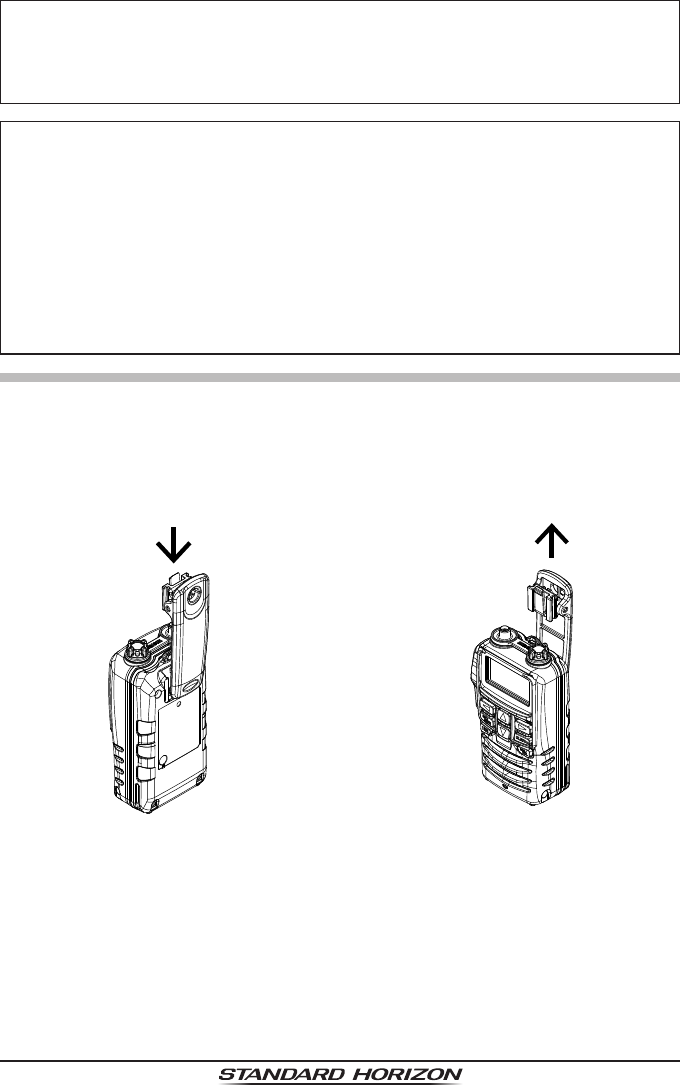
5.3 BELT CLIP INSTALLATION / REMOVAL
r
To install the Belt Clip: align the
Belt Clip to the niche on the rear
of the transceiver, then slide the
Belt Clip downward until it locks
in place with a “Click”.
r
To remove the Belt Clip: press
the Belt Clip Tab away from the
rear of the transceiver to unlock
the Belt Clip, then slide the Belt
Clip upward to remove it.
ApplicationforFCC/IC
FCCID:K6630623X30IC:511B-30623X30
HX40
Page 12
6. CONTROLS AND INDICATORS
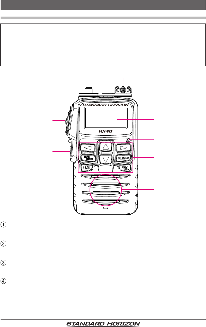
6.1 CONTROLS AND SWITCHES
NOTE
This section denes each control of the transceiver. For detailed operating
instructions, refer to section “7. BASIC OPERATION”. Refer to the below
illustration for the locations of the following controls, switches, and con-
nections.
ANT Jack (Top Panel)
The supplied CAT460 exible antenna is attached here.
PTT (PUSH-TO-TALK) Switch (Left Side Panel)
When pushed activates the transmitter.
POWER Switch (Left Side Panel)
Press and hold this key to turn the radio “ON” or “OFF”.
MIC/SP Jack (Top Panel)
The jack accepts the optional SSM-14A Speaker/Microphone, MH-
73A4B Submersible Speaker/Microphone, SSM-64A VOX Headset, or
SSM-55A Earpiece/Microphone. When this jack is used, the internal
speaker and microphone are disabled.
ApplicationforFCC/IC
FCCID:K6630623X30IC:511B-30623X30

Page 13
HX40
LCD Display
The display shows the current operating conditions (See the LCD indica-
tors illustrated on page 14 & 15).
Microphone
The internal microphone is located here.
When transmitting, position the microphone about 1/2 to 1 inch (1.2 ~
2.5 cm) away from your mouth. Speak slowly and clearly into the micro-
phone.
Keypad
p (UP) Key
Press this key to change the operating channel, the audio volume level,
or the squelch threshold level.
Pressing the key momentarily, will increase the channel (or level) one
step. Holding the key, will increase the channel (or level) continuously.
q (DOWN) Key
Press this key to change the operating channel, the audio volume level,
or the squelch threshold level.
Press the key momentarily, will decrease the channel (or level) one step.
Holding the key, will decrease the channel (or level) continuously.
t & u Keys
When the soft keys are displayed on the channel display screen, press
these keys to select the soft key functions.
Note:
The soft keys can be customized using the Setup Menu mode de-
scribed in section “7.12 Soft Keys”. When one of the soft keys is
pressed briey, the functions will appear at the bottom on the dis-
play.
Press these keys to toggle the on-screen menus right or left.
ENT/MENU Key
Pressing while the soft keys are displayed will enter the selected soft key.
Press to access MENU.
Secondary use:
Press and hold to access SETUP Mode.
CLR/ Key
Press this key to cancel a function or menu selection.
Secondary use:
Press and hold this key to lock or unlock the keypad.
ApplicationforFCC/IC
FCCID:K6630623X30IC:511B-30623X30
HX40
Page 14
SQL/VOL Key
Press this key to enable the audio volume adjustment.
Then press this key again to enable the squelch threshold level adjust-
ment.
Secondary use:
Press and hold this key to open the squelch, allowing you to monitor the
operating channel. Press the key again to resume normal (squelch con-
trolled) monitoring.
16/S Key
Pressing this key immediately recalls channel 16 from any channel se-
lection. Press and hold 16/S Key to recall the sub channel.
Speaker
The internal speaker is located here.
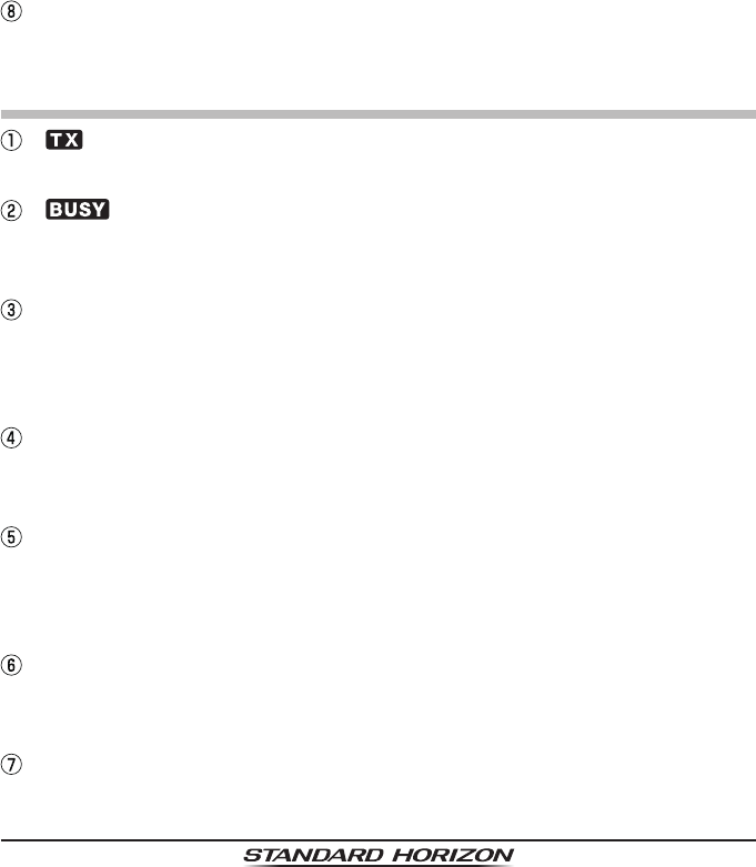
6.2 LCD INDICATORS
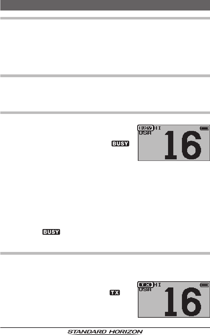
“ ” Indicator
This indicator appears during transmission.
“ ” Indicator
This indicator appears when a signal is being received or the radio is un-
squelched.
“USA”/“INTL”/“CAN” Indicator
These indicators show the “band” of operation.
“USA” indicates the USA band; “INTL” indicates the International band;
and “CAN” indicates the Canadian band.
“DW” Indicator
DW: Dual Watch is activated.
TW: Tri-Watch is activated.
TRANSMIT POWER Indicator
“HI”: 6 W
“MD”: 2.5 W
“LO”: 1 W
“MEM” Indicator
This indicator shows the channel is registered in the transceiver “Scan
Memory”.
“P-SET” Indicator
Shown when the channel is programmed into the Preset Channel memory.
ApplicationforFCC/IC
FCCID:K6630623X30IC:511B-30623X30
Page 15
HX40
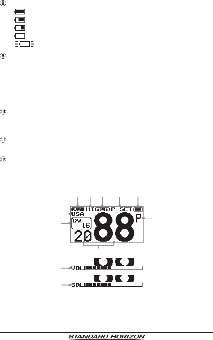
Battery Indicator
“ ”: Full battery
“ ”: Lower battery
“ ”: Battery is low
“ ”: Battery is empty
“ (Blinking)”: Prepare to charge the battery
“P” Indicator
Shown when the channel is set as the Priority Channel.
“D” Indicator
S
hown when the Dual Watch function is enabled in FM radio mode.
“T” Indicator
S
hown when the Triple Watch function is enabled in FM radio mode.
Channel Display
The operating channel is shown on the LCD in both the transmit and the
receive modes.
VOL Indicator
This indicator shows the receive audio volume level.
SQL Indicator
This indicator shows the squelch setting level.
①② ⑥⑤ ⑦ ⑧
⑨
③
④
⑩
⑪
⑫
ApplicationforFCC/IC
FCCID:K6630623X30IC:511B-30623X30
HX40
Page 16
7. BASIC OPERATION
7.1 PROHIBITED COMMUNICATIONS
The FCC prohibits the following communications:
False distress or emergency messages.
Messages to “any boat” except in emergencies and radio tests.
Messages to or from a vessel on land.
Transmission while on land.
Obscene, indecent, or profane language (potential ne of $10,000).
7.2 INITIAL SETUP
1. To install the antenna onto the transceiver; hold the bottom end of the
antenna, then screw it onto the mating connector on the transceiver until
it is snug. Do not over-tighten.
7.3 RECEPTION
1. Press and hold the POWER switch to turn the radio ON.
2. Press the [SQL/VOL] key, when the VOL
indicator appears on the display, press and
hold the [SQL/VOL] key until the “ ”
indicator appears on the display. This is the
“squelch OFF” state.
3. Press the [p] or [q] key until noise or audio from the speaker is heard at
a comfortable level.
4. Press the [SQL/VOL] key to resume normal (squelch controlled) monitor-
ing.
5. When the VOL indicator disappears, press the [p] or [q] key to select
the desired channel. Refer to the channel chart on page 39 for avail-
able channels.
6. When a signal is received, adjust the volume to the desired listening
level. The “ ” indicator on the LCD is displayed indicating that the
channel is being used or the radio is not squelched.
7.4 TRANSMISSION
1.
Setup the transceiver as described in the “7.3 RECEPTION” discussion above.
2. Before transmitting, monitor the channel and make sure it is clear.
THIS IS AN FCC REQUIREMENT!
3. Press the PTT (Push-To-Talk) switch to
transmit. During transmission, the “ ” in-
dicator will appear on the display.
4. Position the microphone about 1/2 to 1 inch (1.2 ~ 2.5 cm) away from
ApplicationforFCC/IC
FCCID:K6630623X30IC:511B-30623X30

Page 17
HX40
your mouth. Speak slowly and clearly into the microphone.
5. When the transmission is nished, release the PTT switch.
7.4.1 TRANSMIT POWER
The TX output power of the HX40 is set to high level (6 W*) in factory de-
fault, and the “HI” indicator is displayed on the top part of the screen.
To change the TX output power:
1. Press the [◄] or [►] key to display the soft keys.
2. Press the [◄] or [►] key repeatedly, until
[HI], [MD], or [LO] is selected above a soft
key at the bottom of the LCD.
3. Press the [ENT/MENU] key repeatedly to
switch between HI (6 W), MD (2.5 W), or LO
(1 W) output power.
7.4.2 TRANSMIT TIME - OUT TIMER (TOT)
While the PTT switch is held down, transmission time is limited to 5 minutes.
This prevents prolonged (unintentional) transmissions. About 10 seconds
before automatic transmitter shutdown, a warning beep will sound from the
speaker. The transceiver automatically switches to receive mode, even if
the PTT switch continues to be held down. The PTT switch must rst be re-
leased, then wait 10 seconds before transmission may be started again. This
Time-Out-Timer (TOT) prevents a continuous transmission that would result
from an accidentally stuck PTT switch.
7.5 USA, CANADIAN, AND INTERNATIONAL CHANNELS
To change the channel group from USA to International or Canada:
1. Press and hold the [ENT/MENU] key.
2. Press the [▲] or [▼] key to select “CHANNEL SETUP”.
3. Press the [◄] or [►] key to select the [SELECT] soft key, then press the
[ENT/MENU] key.
4. Press the [▲] or [▼] key to select “CHANNEL GROUP”.
5. Press the [ENT/MENU] key.
6. Press the [▲] or [▼] key to select the de-
sired channel group “USA”, “INTERNA-
TIONAL”, or “CANADA”.
7. Press the [ENT/MENU] soft key to store the
selected setting.
8. Press the [CLR/ ] key to return to radio operation.
ApplicationforFCC/IC
FCCID:K6630623X30IC:511B-30623X30
HX40
Page 18
7.6 KEYPAD LOCKING
In order to prevent accidental channel change, the HX40’s keypad may be
locked.
Press and hold the [CLR/] key to lock the keypad (except the PTT, [SQL/
VOL] and [CLR/] keys) so that they are not accidentally changed. “KEY
LOCK” will appear on the entire screen, to indicate that the functions are
locked.
To unlock the keys, press and hold the [CLR/] key until “UNLOCK” ap-
pears.
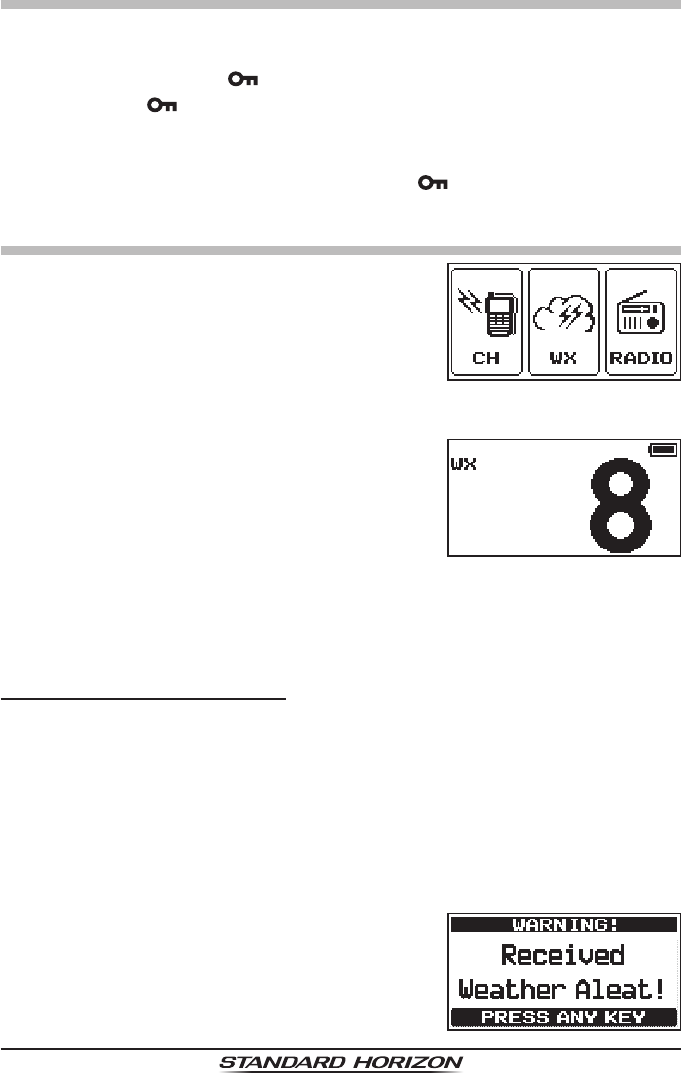
7.7 NOAA WEATHER CHANNELS
1. Press the [ENT/MENU] key to display the
MENU screen.
2. Press the [◄] or [►] key to select the [WX],
then press the [ENT/MENU] key.
The transceiver changes to the weather
channel mode and the radio will be set to
the last used NOAA weather channel.
3. Press the [▲] or [▼] key to select a different
NOAA weather channel.
4. To exit from the NOAA weather channels, press the [ENT/MENU] key to
display MENU screen. Press the [◄] or [►] key to select the [CH], then
press the [ENT/MENU] key. The transceiver will revert to the channel in
use prior to switching to the weather channel mode.
7.7.1 NOAA WEATHER ALERT
In the event of extreme weather disturbances, such as storms and hurri-
canes, the NOAA (National Oceanic and Atmospheric Administration) sends
a weather alert accompanied by a 1050 Hz tone and a subsequent weather
report on one of the NOAA weather channels.
The HX40 can respond to weather alerts; when monitoring a weather chan-
nel; when stopping on the last selected weather channel during scanning
modes; while operating on another working channel; or while listening in the
FM Radio mode.
When an alert is received on a NOAA weather
channel, scanning will stop and the trans-
ceiver will emit a loud beep to alert the user of
a NOAA broadcast. Press any key to stop the
alert.
ApplicationforFCC/IC
FCCID:K6630623X30IC:511B-30623X30

Page 19
HX40
After stopping the beep sound, the weather
alert reception conrmation screen will appear.
Press any key to display a conrmation screen.
The confirmation screen will ask whether to
move to the weather channel, or return to the
marine channel. Press [ENT/MENU] to switch
to the weather channel, or press the [►] key
to select the [NO] soft key, then press [ENT/
MENU] to return to the marine channel.
7.7.2 NOAA WEATHER ALERT TESTING
In order to test this system, NOAA broadcasts the 1050 Hz tone every
Wednesday sometime between 11 AM and 1 PM local time. You may use
this opportunity to test your transceiver periodically to confirm that the
Weather Alert feature is working, or for training crew members on how to
congure the transceiver to receive the NOAA Weather Alerts.
ApplicationforFCC/IC
FCCID:K6630623X30IC:511B-30623X30
HX40
Page 20
7.8 PRESET CHANNELS: INSTANT ACCESS
10 preset channels can be programmed for instant access. Press the [◄] or
[►] key to display the soft keys. Press the [◄] or [►] key repeatedly to select
the [P-SET] soft key. Pressing the [ENT/MENU] key activates the user as-
signed channel bank. If the [ENT/MENU] key is pressed and no preset chan-
nels have been assigned, an alert beep will be emitted from the speaker.
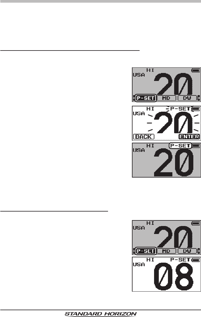
7.8.1 PROGRAMMING PRESET CHANNEL BANKS
1. Select the desired channel to be assigned into the Preset Channel Bank
using the [▲] or [▼] key.
2. Press the [◄] or [►] key to display the soft
keys.
3. Press the [◄] or [►] key repeatedly, until
the [P-SET] soft key is selected at the bot-
tom of the LCD.
4. Press and hold the [ENT/MENU] key until
the “P-SET” icon and channel number are
blinking.
5. Press the [ENT/MENU] key to program the
channel into the preset channel memory.
The “P-SET” icon will appear.
6. Repeat steps 1 through 5 to program the additional channels into the
preset channels. Up to 10 channels can be registered. If you attempt to
register an 11th channel, the error beep will sound.
7.8.2 OPERATION on a Preset Channel
1. Press the [◄] or [►] key to display the soft keys.
2. Press the [◄] or [►] key repeatedly, until
the [P-SET] soft key is selected at the bot-
tom of the LCD.
3. Press the [ENT/MENU] key, then press the
[▲] or [▼] key to select the desired preset
channel.
ApplicationforFCC/IC
FCCID:K6630623X30IC:511B-30623X30
Page 21
HX40
4.
To
return to the previous operation channel, press the [◄] or [►] key to
displays the channel. Press the [◄] or [►] key repeatedly, until the [P-SET]
soft key is selected at the bottom of the LCD. Press the [ENT/MENU]
key. The “P-SET” icon will disappear from the display.
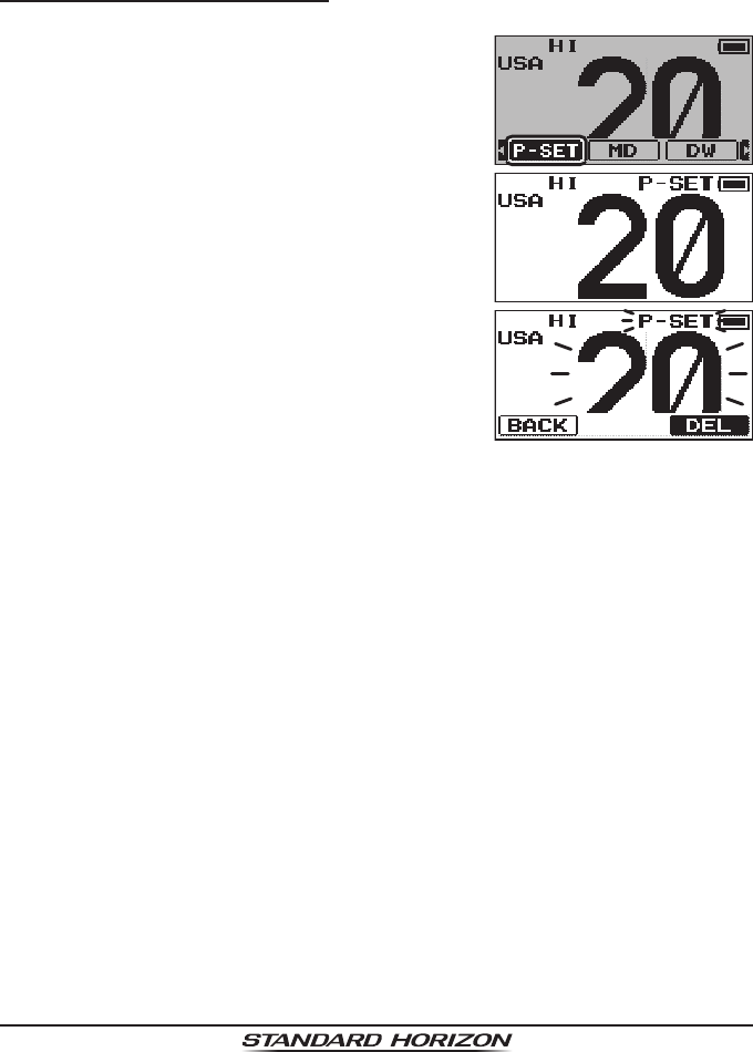
7.8.3 Deleting a Preset Channel
1. Press the [◄] or [►] key to display the soft keys.
2. Then press the [◄] or [►] key repeatedly,
until the [P-SET] soft key is selected.
3. Press the [ENT/MENU] key, then press the
[▲] or [▼] key to select the preset channel
to be deleted.
4. Press the [◄] or [►] key to display the soft
keys, then press the [◄] or [►] key repeat-
edly, until the [P-SET] soft key is selected at
the bottom of the LCD.
5. Press and hold the [ENT/MENU] key until
the “P-SET” icon and channel number are
blinking.
6. Press the [◄] or [►] key repeatedly, until the [DEL] soft key is selected
at the bottom of the LCD. Press the [ENT/MENU] key to delete the chan-
nel from the preset channel memory.
7. To exit from the preset channels delete operation, press the [◄] or [►]
key repeatedly, until the [BACK] soft key is selected at the bottom of the
LCD, then press the [ENT/MENU] key.
ApplicationforFCC/IC
FCCID:K6630623X30IC:511B-30623X30
HX40
Page 22
7.9 SCANNING
The HX40 provides two types of scanning, “Memory Scan” or “Priority
Scan”. “Memory Scan” scans the channels that were programmed into Scan
Memory and also channels stored in the Preset Channel memory. “Priority
Scan” is similar to the “Memory Scan” scan, however it scans the priority
channel (channel 16) and dual watches to channels programmed in memory
scan and preset channel memory. When an incoming signal is detected on
one of the channels during scan, the radio will pause on that channel, allow-
ing you to listen to the incoming transmission.
7.9.1 PROGRAMMING SCAN MEMORY
1. Press and hold the [ENT/MENU] key.
2. Press the [▲] or [▼] key to select “CHANNEL SETUP”.
3. Press the [◄] or [►] key to select the [SELECT] soft key, then press the
[ENT/MENU] key.
4. Press the [▲] or [▼] key to select “SCAN MEMORY”.
5. Press the [ENT/MENU] key.
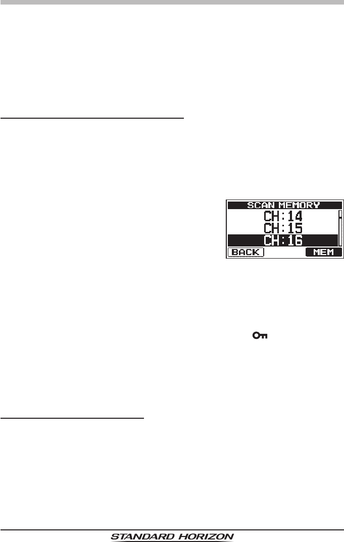
6. Press the [▲] or [▼] key to select a desired
channel to be scanned.
7. Press the [◄] or [►] key to select the [MEM]
soft key, then press the [ENT/MENU] key.
The “ON” icon will appear at the right side of
the selected channel.
8. Repeat step 7 for all the desired channels to be scanned.
9. To REMOVE a channel from the list, select the channel. Press the [◄]
or [►] key to select the [MEM] soft key, then press the [ENT/MENU] key.
The “ON” icon of the selected channel will disappear.
10. When the selections are complete, press the [CLR/ ] key to return to
radio operation.
To check channels to be scanned, press the [▲] or [▼] key repeatedly, to
display each channel. The “MEM” icon will appear when a designated mem-
ory channel is displayed.
7.9.2 SELECTING SCAN TYPE
1. Press and hold the [ENT/MENU] key.
2. Press the [▲] or [▼] key to select “CHANNEL SETUP”.
3. Press the [◄] or [►] key to select the [SELECT] soft key, then press the
[ENT/MENU] key.
4.
Press the [▲] or [▼] key to select “SCAN TYPE”.
5. Press the [ENT/MENU] key.
ApplicationforFCC/IC
FCCID:K6630623X30IC:511B-30623X30
Page 23
HX40
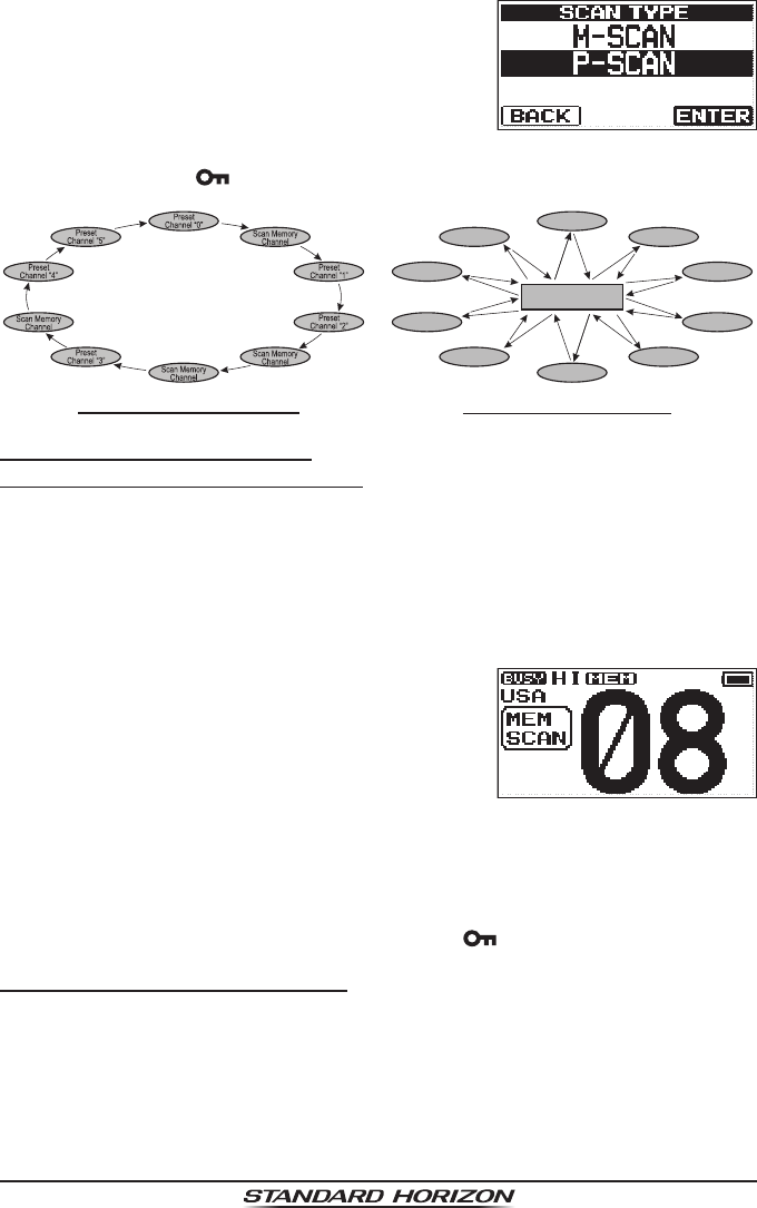
6. Press the [▲] or [▼] key to select “M-SCAN”
or “P-SCAN”.
7. Press the [ENT/MENU] key to store the selected setting.
8. Press the [CLR/ ] key to return to radio operation.
Memory Scan (M-SCAN)
Scan Memory
Channel
Scan Memory
Channel
Scan Memory
Channel
Scan Memory
Channel
Preset
Channel 4
Preset
Channel 5
Priority Channel
Preset
Channel 0
Preset
Channel 1
Preset
Channel 2
Preset
Channel 3
Priority Scan (P-SCAN)
7.9.3 SCANNING OPERATION
7.9.3.1 Memory Scanning (M-SCAN)
1. Set the scan type to “M-SCAN” in the SETUP menu (refer to “7.9.2 SE-
LECTING SCAN TYPE”).
2. Press the [SQL/VOL] key twice, then press the [▲] or [▼] key until the
squelch background noise disappears.
3. Press the [◄] or [►] key repeatedly, until the [SCAN] soft key is selected
at the bottom of the LCD.
4. Press the [ENT/MENU] key.
“MEM SCAN” will appear on the display.
Scanning will proceed from the lowest to the
highest programmed channel number and
preset channel (described in the next sec-
tion). Scanning will stop on a channel when
a transmission is received.
The channel number will blink during recep-
tion.
5. To stop scanning, press the [16/S] or [CLR/ ] key.
7.9.3.2 Priority Scanning (P-SCAN)
1. Set the scan type to “P-SCAN” in the SETUP menu (refer to “7.9.2 SE-
LECTING SCAN TYPE”).
2. Press the [SQL/VOL] key twice, then press the [▲] or [▼] key until the
squelch background noise disappears.
3. Press the [◄] or [►] key repeatedly, until the [SCAN] soft key is selected
at the bottom of the LCD.
ApplicationforFCC/IC
FCCID:K6630623X30IC:511B-30623X30
HX40
Page 24
4. Press the [ENT/MENU] key.
“PRI SCAN” appears on the display. Scanning will proceed between the
memory channels, the preset channels, and the priority channel.
The priority channel will be scanned after each programmed channel.
5. To stop scanning, press the [16/S] or [CLR/ ] key.
7.10 MULTI WATCH (TO PRIORITY CHANNEL)
Multi watch is used to scan two or three channels for communications.
m In Dual Watch, a normal VHF channel and the priority channel are
scanned alternately.
m In Triple Watch, a normal VHF channel, the priority channel, and the sub
channel are scanned alternately.
When a signal is received on the normal channel the radio briey switches
between the normal channel and the priority channel to look for a transmis-
sion. If the radio receives communications on the priority channel the radio
stops and listens to the priority channel until communication ends and then
starts dual or triple watch scan again.
NOTE
The priority channel and sub channel may be changed from CH16 (default)
and CH9 (default) to another channel. Refer to section “ PRIORITY CH” or
“SUB SUB CH” (see page 30 for details).
7.10.1 Setting up the Multi Watch Operation
1. Press and hold the [ENT/MENU] key.
2. Press the [▲] or [▼] key to select “CHANNEL SETUP”.
3. Press the [◄] or [►] key to select the [SELECT] soft key, then press the
[ENT/MENU] key.
4. Press the [▲] or [▼] key to select “MULTI WATCH”.
5. Press the [ENT/MENU] key.
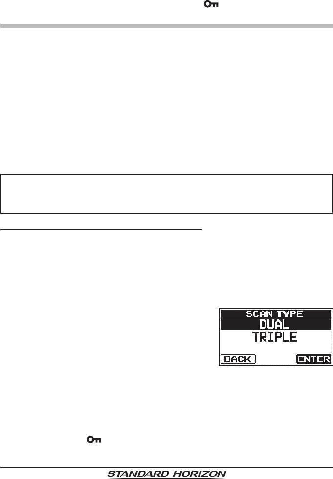
6. Press the [▲] or [▼] key to select “DUAL”
or “TRIPLE”.
DUAL (Dual Watch): The HX40 watches the activity of the current
channel and the priority channel.
TRIPLE (Triple Watch):
The HX40 watches the activity of the priority chan-
nel, the sub channel, and the current channel.
7. Press the [ENT/MENU] key to store the selected setting.
8. Press the [CLR/ ] key to return to radio operation.
ApplicationforFCC/IC
FCCID:K6630623X30IC:511B-30623X30
Page 25
HX40
7.10.2 Starting the Dual Watch
1. Press the [SQL/VOL] key twice, then press the [▲] or [▼] key until the
background squelch noise disappears.
2. Press the [▲] or [▼] key to select a channel you wish to dual watch.
3. Press the [◄] or [►] key to display the soft keys.
4. Press the [◄] or [►] key repeatedly, until the [DW] soft key at the bottom
of the LCD is selected.
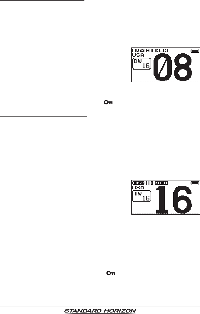
5. Press the [ENT/MENU] key.
The radio will monitor the priority channel
and the working channel that were selected
in step 2.
6. While a signal is received on the channel selected in step 2, the HX40
will dual watch to the priority channel periodically.
7. To stop dual watch, press the [CLR/ ] key.
7.10.3 Starting the Triple Watch
You may change the Dual Watch feature to Triple Watch via the Menu (“Set”)
Mode. Triple Watch scans the priority channel, the sub channel, and one
working channel.
1. Press the [▲] or [▼] key to select the working channel to scan along with
the sub channel and the priority channel.
2. Press the [◄] or [►] key to display the soft keys.
3. Press the [◄] or [►] key repeatedly, until the [TW] soft key at the bottom
of the LCD is selected.
4. Press the [ENT/MENU] key to activate the
Triple Watch feature.
5. When a transmission is received on the priority channel, the HX40 will
remain on the priority channel until the incoming signal disappears.
6. When a transmission is received on the sub channel, the HX40 will Dual
watch the priority channel and the sub channel.
7. When the HX40 receives a transmission on the working channel, the
HX40 will Triple Watch between the working channel, the priority chan-
nel, and sub channel.
8. To stop Triple watch, press the [CLR/ ] key.
ApplicationforFCC/IC
FCCID:K6630623X30IC:511B-30623X30
HX40
Page 26
7.11 Listening to the FM Radio
The HX40 includes provision for FM broadcast reception.
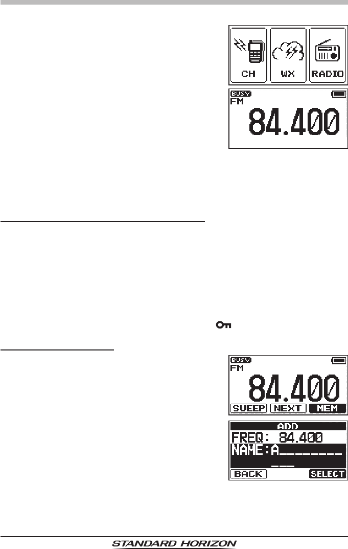
1. Press the [◄] or [►] key to select the [RA-
DIO], then press the [ENT/MENU] key.
The FM broadcast coverage is 65.000 to
108.000 MHz (100 kHz step) and utilizes
Wide-FM mode.
2. Press the [▲] or [▼] key to select the de-
sired frequency.
3. To exit from the FM Broadcast Reception mode, press the [ENT/MENU]
key to display the MENU screen. Press the [◄] or [►] key to select [CH],
then press the [ENT/MENU] key. The transceiver will revert to the chan-
nel in use prior to switching to the FM Broadcast band.
FM broadcast Frequency sweep operation
1. Recall the FM Broadcast Reception mode (see above).
2. Press the [◄] or [►] key to select the [SWEEP] soft key, then press the
[ENT/MENU] key to start sweep operation.
Sweeping will proceed from the lowest to the highest frequencies (step
100 kHz).
If the radio receives an FM station, the sweep will stop on the received
frequency.
3. To cancel sweep operation, press the [CLR/] key, the [▲] or [▼] key.
Store the FM frequency
1. While listening in the FM Broadcast receive
mode, select the desired FM frequency.
2. Press the [◄] or [►] key to select the [MEM]
soft key, then press the [ENT/MENU] key to
display the “ADD” screen.
3. Press the [ENT/MENU] key.
ApplicationforFCC/IC
FCCID:K6630623X30IC:511B-30623X30
Page 27
HX40
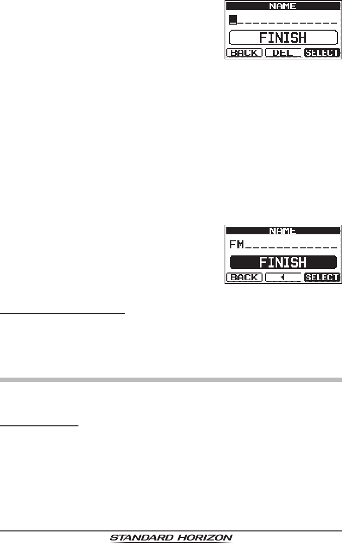
4. Press the [▲] or [▼] key to scroll through
the letters and choose the rst letter of the
name for the FM frequency.
5. Press the [ENT/MENU] key to store the rst
letter of the name and step to the next letter
to the right.
6. Repeat steps 4 and 5 until the name is complete. The name can consist
of up to twelve characters, and if you do not use all twelve characters,
press the [ENT/MENU] key to move to the next spaces. This method can
also be used to enter a blank space within the name.
If a mistake was made entering in the name, press the [◄] or [►] key to
select the [DEL] soft key, then press the [ENT/MENU] key to delete the
wrong character.
7. When the twelve letters or spaces have
been entered, select “FINISH”. Press the
[ENT/MENU] key to store the FM frequency.
To return to the input, press the [◄] or [►]
key to select the [ ◄ ] soft key, then press the
[ENT/MENU] key.
Memory Frequency Recall
1. Press the [◄] or [►] key to select the [NEXT] soft key, then press the
[ENT/MENU] key to recall the Last displayed FM broadcast memory.
2. Then press the [ENT/MENU] key repeatedly to step sequentially through
the FM broadcast memories.
7.12 Soft Keys
The soft key functions may be recongured, and the duration time of the soft
key icon display, after a key is pressed, can be changed.
Key Assignment
1. Press and hold the [ENT/MENU] key.
2.
Press the [▲] or [▼] key to select “CONFIG”.
3.
Press the [◄] or [►] key to select the [SELECT] soft key, then press the
[ENT/MENU] key.
4.
Press the [▲] or [▼] key to select “KEY SETUP”
, then press the [ENT/
MENU] key.
ApplicationforFCC/IC
FCCID:K6630623X30IC:511B-30623X30
HX40
Page 28
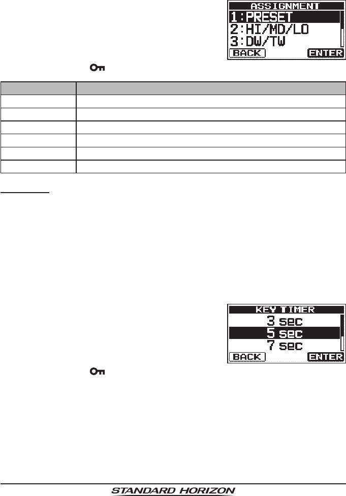
5. Press the [◄] or [►] key to select “ASSIGNMENT”, then press the [ENT/
MENU] key.
6. Press the [▲] or [▼] key to select the key number to be programmed,
and then press the [ENT/MENU] key.
7. Press the [▲] or [▼] key to select a new
function to be assigned to the soft key, and
press the [ENT/MENU] soft key. Available
functions are listed below.
c
8. Press the [CLR/ ] key to return to radio operation.
Display Function
PRESET Programs or deletes the preset memory channel.
HI/MD/LO Selects transmit power.
DW/TW Turns dual or triple watch scan ON/OFF.
MEMORY Add or remove channels from memory channel scan.
SCAN Turns the scanning function ON/OFF.
NONE No function.
Key Timer
1. Press and hold the [ENT/MENU] key.
2. Press the [▲] or [▼] key to select “CONFIG”.
3. Press the [◄] or [►] key to select the [SELECT] soft key, then press the
[ENT/MENU] key.
3. Select “KEY SETUP” with the [▲] or [▼] key, then press the [ENT/
MENU] soft key.
4. Select “KEY TIMER” with the [▲] or [▼] key, then press the [ENT/MENU]
soft key.
5. Press the [▲] or [▼] key to select the de-
sired time, and press the [ENT/MENU] soft
key.
c
6. Press the [CLR/ ] key to return to radio operation.
ApplicationforFCC/IC
FCCID:K6630623X30IC:511B-30623X30
Page 29
HX40
8. MENU (“SETUP”)
The HX40’s Menu Mode allows enables a number of the HX40 operating pa-
rameters to be custom-congured.
Use the following procedure to activate and set The Menu Mode parameters:
1. Press and hold the [ENT/MENU] key.
2. Press the [▲] or [▼] key to select the desired menu item.
3. Press the [▲] or [▼] key to select the key number to be programmed,
and then press the [ENT/MENU] key.
4. Press the [▲] or [▼] key to select the desired menu item, then press the
[ENT/MENU] key.
5. Press the [▲] or [▼] key to select the desired setting.
6. Press the [ENT/MENU] key to store the new setting.
7. Press the [CLR/ ] key to return to radio operation.
CHANNEL SETUP
CHANNEL GROUP
This menu item enables chaning the channel group from USA channels, to
Canada channels, or International channels.
Refer to the section “7.5 USA, CANADIAN, AND INTERNATIONAL CHAN-
NELS” for details.
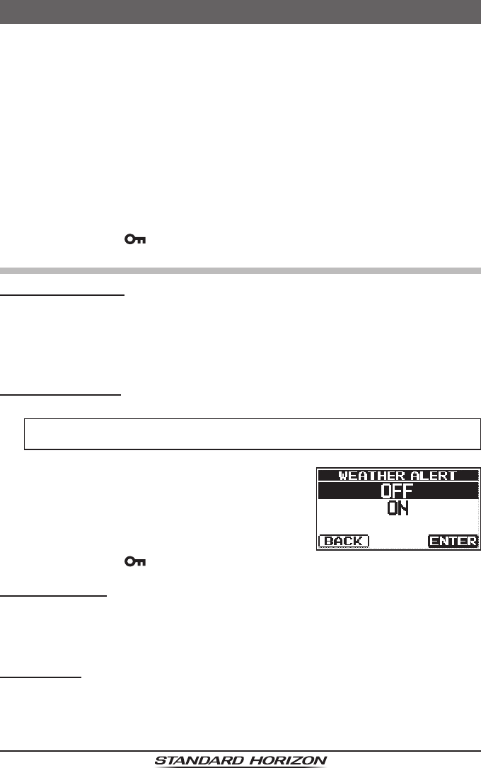
WEATHER ALERT
Enables/disables the NOAA Weather Alert function. The default setting is “OFF”.
1.
Press and hold [ENT/MENU] “CHANNEL SETUP” “WEATHER ALERT”
2. Press the [▲] or [▼] key to select “ON” or
“OFF”.
3. Press the [ENT/MENU] key to store the new
setting.
4. Press the [CLR/ ] key to return to radio operation.
SCAN MEMORY
Before scanning can begin, the desired scan channels must be programmed.
This selection allows channels to be stored to the scan memory.
Refer to section “7.9.1 PROGRAMMING SCAN MEMORY” for details.
SCAN TYPE
This selection is used to change the scan mode between “M-SCAN” (Memory
Scan) and “P-SCAN” (Priority Scan). The default setting is “P-SCAN”.
Refer to section “7.9.2 SELECTING SCAN TYPE” for details.
ApplicationforFCC/IC
FCCID:K6630623X30IC:511B-30623X30
HX40
Page 30
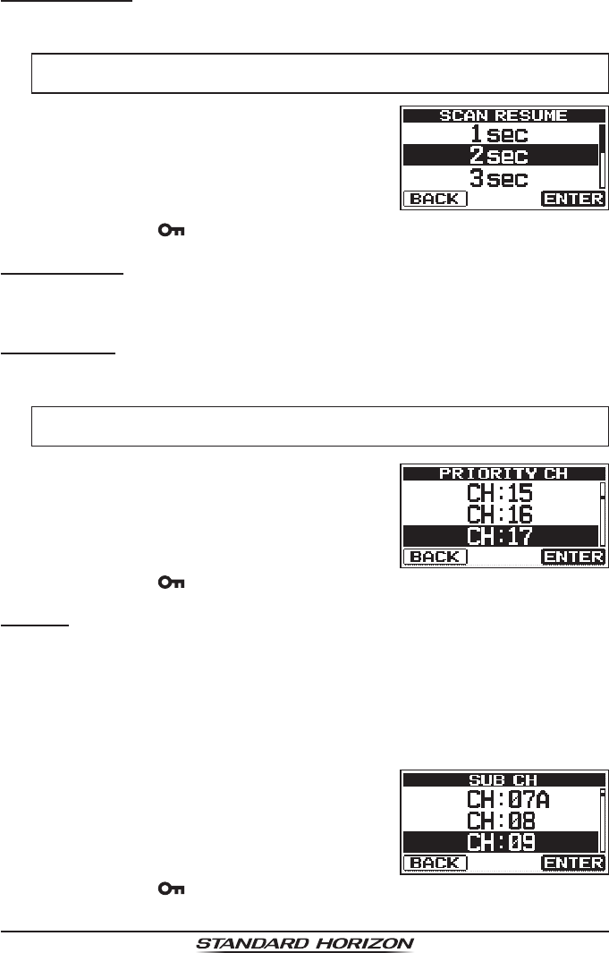
SCAN RESUME
This selection is used to select the time the HX40 waits after a transmission ends
before the radio starts to scan channels again. The default setting is 2 seconds
.
1.
Press and hold [ENT/MENU] “CHANNEL SETUP” “SCAN RESUME”
2. Press the [▲] or [▼] key to select the de-
sired time. The resume time can be set to “1
sec” through “5 sec”.
3. Press the [ENT/MENU] key to store the new
setting.
4. Press the [CLR/ ] key to return to radio operation.
MULTI WATCH
This selection is used to choose between “Dual Watch” and “Triple Watch”.
Refer to section “7.10.1 Setting up the Multi Watch Operation” for details.
PRIORITY CH
This procedure may be used to designate a different priority channel when
priority scanning. By default, the radio priority channel is set to Channel 16.
1.
Press and hold [ENT/MENU] “CHANNEL SETUP” “
PRIORITY CH
”
2. Press the [▲] or [▼] key to select the de-
sired channel to be a priority.
3. Press the [ENT/MENU] key to store the new
setting.
4. Press the [CLR/ ] key to return to radio operation.
SUB CH
By default, the sub channel is set to Channel 9. This procedure allows the
radio to assign a different sub channel for instant access.
1. Press and hold the [ENT/MENU] key.
2. Press the [▲] or [▼] key to select “CHANNEL SETUP”, then press the
[ENT/MENU] key.
3.
Select “SUB CH” with the [▲] or [▼] key, then press the[ENT/MENU] key.
4. Press the [▲] or [▼] key to select the de-
sired channel to be the sub channel.
5. Press the [ENT/MENU] key to store the new
setting.
6. Press the [CLR/ ] key to return to radio operation.
ApplicationforFCC/IC
FCCID:K6630623X30IC:511B-30623X30

Page 31
HX40
FM SETUP
ADD
1.
Press and hold [ENT/MENU] “
FM SETUP
” “
ADD
”
2. Press the [▲] or [▼] key to select “FREQ”, then press the [ENT/MENU]
key.
3. Press the [▲] or [▼] key to scroll through
the rst position numbers of the frequency.
4. Press the [ENT/MENU] key to store the rst
number in the frequency and step to the
next position to the right.
5. Repeat steps 3 and 4 until the frequency is complete.
If a mistake was made entering in the frequency, press the [◄] or [►]
soft key to select the [DEL] soft key, then press the [ENT/MENU] key to
delete the wrong number.
6. After the four numbers have been entered, “FINISH” is selected. Press
the [ENT/MENU] key to save and exit to the “ADD” screen.
7. Press the [▼] key, then press the [ENT/MENU] key.
8. Press the [▲] or [▼] key to scroll through the rst letter of the name of
the frequency.
9. Press the [ENT/MENU] key to store the rst letter in the name and step
to the next position to the right.
10. Repeat steps 8 and 9 until the name is complete. The name can consist
of up to twelve characters, and if you do not use all twelve characters,
press the [ENT/MENU] key to move to the next spaces. This method can
also be used to enter a blank space in the name.
If a mistake was made entering in the name, press the [◄] or [►] key to
select the [DEL] soft key, then press the [ENT/MENU] key to delete the
wrong character.
11. After the twelve letters or spaces have been entered, press the [ENT/
MENU] key, “FINISH” is selected. Press the [ENT/MENU] key to stored
the FM frequency.
To return to the input, press the [◄] or [►] key to select the [ ◄ ] soft key,
then press the [ENT/MENU] key.
ApplicationforFCC/IC
FCCID:K6630623X30IC:511B-30623X30
HX40
Page 32
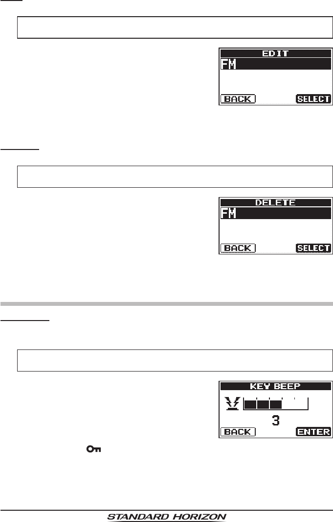
EDIT
This selection is used to edit the FM Broadcast frequency and name.
1.
Press and hold [ENT/MENU] “
FM SETUP
” “
EDIT
”
2. Press the [▲] or [▼] key to select the
memory to be edited, then press the [ENT/
MENU] key.
3. Use the same procedure as described in steps 3 to 11 of “ADD” in the
previous section.
DELETE
This selection can delete the frequency data stored on an FM Broadcast memory.
1.
Press and hold [ENT/MENU] “
FM SETUP
” “
DELETE
”
2. Press the [▲] or [▼] key to select the
memory to be deleted, then press the [ENT/
MENU] key.
The delete conrmation screen will appear.
3. Press the [▲] or [▼] key to select “OK?” (delete) or “CANCEL” (cancel),
then press the [ENT/MENU] key.
CONFIG
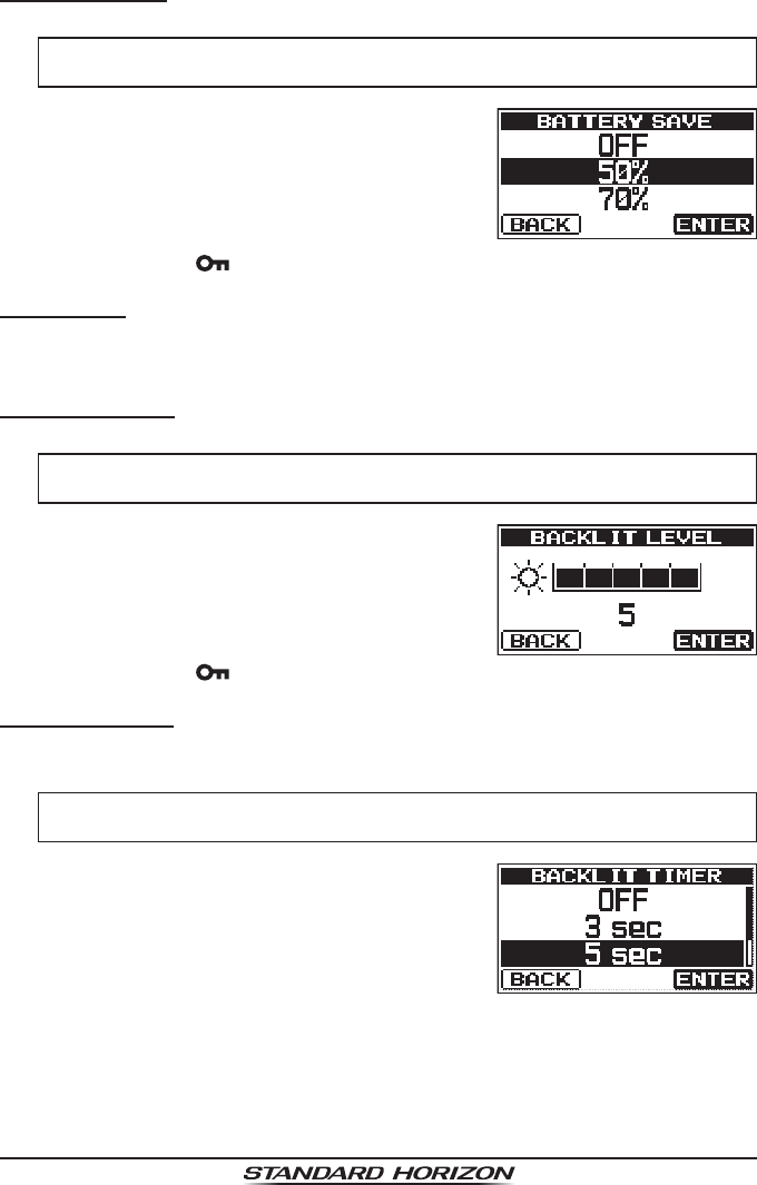
KEY BEEP
This selection is used to select the beep tone volume level when a key is
pressed.
1.
Press and hold [ENT/MENU] “
CONFIG
” “
KEY BEEP
”
2. Press the [▲] or [▼] key to select the de-
sired level. The beep level can be set from
“1” to “5”, or “OFF”.
3. Press the [ENT/MENU] key to store the se-
lected level.
4. Press the [CLR/ ] key to return to radio operation.
ApplicationforFCC/IC
FCCID:K6630623X30IC:511B-30623X30
Page 33
HX40
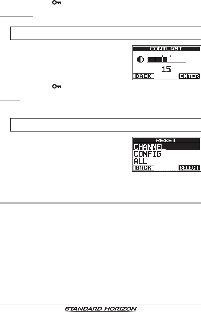
BATTERY SAVE
This function allows you to change the battery save mode setting.
1.
Press and hold [ENT/MENU] “
CONFIG
” “
BATTERY SAVE
”
2. Press the [▲] or [▼] key to select the de-
sired setting. You can select one from “OFF”,
“50%”, “70%”, “80%”, or “90%”.
3. Press the [ENT/MENU] key to store the new
setting.
4. Press the [CLR/] key to return to radio operation.
KEY SETUP
The function assigned to the function screen Soft Keys can be changed (see
page 27 “7.12 Soft Keys”).
BACKLIT LEVEL
The backlight brightness may be adjusted in 5 levels.
1.
Press and hold [ENT/MENU] “
CONFIG
” “
BACKLIT LEVEL
”
2. Press the [▲] or [▼] key to select the de-
sired setting, from “1” to “5”, or “OFF”.
3. Press the [ENT/MENU] key to store the se-
lected level.
4. Press the [CLR/ ] key to return to radio operation.
BACKLIT TIMER
This menu selection is used to setup the illumination time of the display and
keypad.
1.
Press and hold [ENT/MENU] “
CONFIG
” “
BACKLIT TIMER
”
2. Press the [▲] or [▼] key to select the de-
sired time.
OFF: Disables the display/key-
pad lamp illumination.
3/5/10/30 Sec: Illuminates the display/key-
pad for the selected time
when any key (except the
PTT switch) is pressed.
CONTINUOUS: Illuminates the display/key-
pad continuously.
ApplicationforFCC/IC
FCCID:K6630623X30IC:511B-30623X30
HX40
Page 34
3. Press the [ENT/MENU] key to store the new setting.
4. Press the [CLR/ ] key to return to radio operation.
CONTRAST
The contrast may be adjusted in 30 levels.
1.
Press and hold [ENT/MENU] “
CONFIG
” “
CONTRAST
”
2. Press the [▲] or [▼] key to select the de-
sired level. The contrast level can be set
from “0” to “30” (“15” is default).
3. Press the [ENT/MENU] key to store the se-
lected level.
4. Press the [CLR/ ] key to return to radio operation.
RESET
The memories and settings of each setup category may be initialized inde-
pendently, or the transceiver may be reset to the original factory settings.
1.
Press and hold [ENT/MENU] “
CONFIG
” “
RESET
”
2. Press the [▲] or [▼] key to select the de-
sired category from: “CHANNEL”, “CON-
FIG”, or “ALL” (all settings except the MMSI
will be initialized).
3. Press the [ENT/MENU] key.
4. Press the [▲] or [▼] key to select “OK?”, then press the [ENT/MENU]
key.
ABOUT...
Displays the version of the software currently operating on the transceiver.
ApplicationforFCC/IC
FCCID:K6630623X30IC:511B-30623X30
Page 35
HX40
9. MAINTENANCE
9.1 GENERAL
The inherent quality of the solid-state components in STANDARD HORIZON
radios will provide many years of continuous use. Take the following precau-
tions to prevent damage to the radio.
Never key the microphone unless an antenna or suitable dummy load is
connected to the transceiver.
Use only STANDARD HORIZON-approved accessories and replacement parts.
9.2 FACTORY SERVICE
In the unlikely event that the radio fails to perform or needs servicing, please
contact the following:
Standard Horizon
Attention Marine Repair Department
6125 Phyllis Drive, Cypress, California 90630, U.S.A.
Telephone (800) 366-4566
For repairs in Canada
Westcom Marine
488 East 62nd Avenue Vancouver BC V5X2G1
Phone (604)327-6280
An “RA” Return Authorization number is not necessary to send a product
in for service. Include a brief note describing the problem along with your
name, return address, phone number, and proof of purchase.
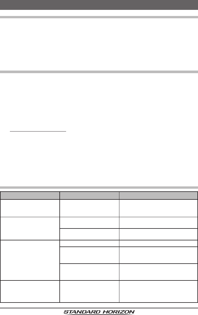
9.3 TROUBLESHOOTING CHART
SYMPTOM PROBABLE CAUSE REMEDY
The USA/INTL/CAN
modes do not function.
Proper operation not fol-
lowed.
Specify the item number from
“SETUP MENU” – “CHANNEL
SETUP” – “CHANNEL GROUP”.
Cannot output sound by
pressing and holding the
[SQL/VOL] key.
Low battery. Charge battery. Refer to section 5.2
of this manual.
Audio volume level is too
low.
Press the [▲] key until background
noise outputs.
Charge indicator does
not appear on the display
when charging a battery.
Defective built-in battery. Contact Standard Horizon dealer.
The transceiver is not set
onto the SBH-27 Charger
Cradle properly.
Set the transceiver onto the SBH-
27 Charger Cradle properly.
Power is not supplied
to the SBH-27 Charger
Cradle.
Connect SAD-23B or E-DC-19A
to the SBH-27 Charger Cradle for
AC/DC power supplies.
Cannot turn the trans-
ceiver OFF.
The transceiver is unrespon-
sive to keypad operation.
The Micro Computer has
frozen.
Press and hold the POWER switch
for over 15 seconds to restart the
transceiver.
ApplicationforFCC/IC
FCCID:K6630623X30IC:511B-30623X30

HX40
Page 36
10. VHF MARINE CHANNEL ASSIGNMENTS
Tables on the following pages list the VHF Marine Channel assignments for
USA. and International use. Below are listed some data about the charts.
1. VTS. Where indicated, these channels are part of the U.S. Coast Guard’s
Vessel Trafc System.
2. Alpha channel numbers, that is, channel numbers followed by the letter A
(such as Channel 07A) are simplex channels on the USA. or Canadian
channel assignments whose counterparts in the International assign-
ments are duplex channels. International channels do not use “alpha”
numbers. If you call the Coast Guard on Channel 16, they will sometimes
ask you to “go to channel 22 Alpha.” This is a channel assigned to USA,
and Canadian Coast Guards for handling distress and other calls. If your
radio is set for International operation you will go to Channel 22 instead
of 22A, and will not be able to communicate with the Coast Guard. To
use Channel 22A, your radio must be set for USA or Canada operation,
usually by a U/I/C (USA/International/Canada) control or combination of
controls. Channel 22 (without an “A”) is an International duplex channel
for port operations. Some radios indicate an “A” adjacent to the alpha
channels on the display; on others “alpha” is not indicated but the proper
channel is selected based on the U/I/C setting.
3. Bridge-to-Bridge channels (for example, Channel 13) are for use by
bridge operators on inter-coastal waterways and rivers. It is also used by
marine vessels in the vicinity of these bridges for navigation and for com-
municating with the bridge operators. Note that a limit of 1 Watt is speci-
ed for these channels.
4. The S/D column on the chart indicates either S (simplex) or D (duplex).
Simplex means transmitting and receiving on the same frequency. Only
one party at a time can talk, unlike a telephone. Be sure to say “over”
and release your microphone push-to-talk switch at the end of each
transmission. Duplex operation involves the use of one frequency for
transmitting and a separate frequency for receiving. On channels speci-
ed as duplex on the charts, correct mode of operation is established au-
tomatically by your radio when you select a channel; you cannot change
the mode. And you still must release the push-to-talk switch after each
transmission in order to listen to the radio.
5. Channels normally used by recreational boaters are those that include
the term “non-commercial” in the Channel Use column of the chart.
Some of these are shared with other users and some are used only in
certain geographic regions.
ApplicationforFCC/IC
FCCID:K6630623X30IC:511B-30623X30

Page 37
HX40
6. Marine vessels equipped with VHF radios are required to monitor Chan-
nel 16.
7. 156.050 MHz and 156.175 MHz are available for port operations and
commercial communications purposes when used only within the U.S.
Coast Guard designated Vessel Trafc Services (VTS) area of New Or-
leans, on the lower Mississippi River from the various pass entrances
in the Gulf of Mexico to Devil’s Swamp Light at River Mile 242.4 above
head of passes near Baton Rouge.
8. 156.250 MHz is available for port operations communications use only
within the U.S. Coast Guard designated VTS radio protection areas of
New Orleans and Houston described in Sec. 80.383. 156.250 MHz is
available for intership port operations communications used only within
the area of Los Angeles and Long Beach harbors, within a 25- nautical
mile radius of Point Fermin, California.
9. 156.550 MHz, 156.600 MHz and 156.700 MHz are available in the U.S.
Coast Guard designated port areas only for VTS communications and
in the Great Lakes available primarily for communications relating to the
movement of ships in sectors designated by the St. Lawrence Seaway
Development Corporation or the U.S. Coast Guard. The use of these fre-
quencies outside VTS and ship movement sector protected areas is per-
mitted provided they cause no interference to VTS and ship movement
communications in their respective designated sectors.
10. Use of 156.875 MHz is limited to communications with pilots regarding
the movement and docking of ships. Normal output power must not ex-
ceed 1 watt. 5: 156.375 MHz and 156.650 MHz are available primarily for
intership navigational communications. These frequencies are available
between coast and ship on a secondary basis when used on or in the
vicinity of locks or drawbridges. Normal output power must not exceed 1
watt. Maximum output power must not exceed 10 watts for coast stations
or 25 watts for ship stations.
11. On the Great Lakes, in addition to bridge-to-bridge communications,
156.650 MHz is available for vessel control purposes in established
vessel trafc systems. 156.650 MHz is not available for use in the Mis-
sissippi River from South Pass Lighted Whistle Buoy “2” and Southwest
Pass entrance Mid-channel Lighted Whistle Buoy to mile 242.4 above
Head of Passes near Baton Rouge. Additionally it is not available for use
in the Mississippi River-Gulf Outlet, the Mississippi River-Gulf Outlet Ca-
nal, and the Inner Harbor Navigational Canal, except to aid the transition
from these areas.
ApplicationforFCC/IC
FCCID:K6630623X30IC:511B-30623X30

HX40
Page 38
12. Use of 156.375 MHz is available for navigational communications only
in the Mississippi River from South Pass Lighted Whistle Buoy “2” and
Southwest Pass entrance Mid channel Lighted Whistle Buoy to mile
242.4 above head of Passes near Baton Rouge, and in addition over the
full length of the Mississippi River-Gulf Outlet Canal from entrance to its
junction with the Inner Harbor Navigation Canal, and over the full length
of the Inner Harbor Navigation Canal from its junction with the Mississippi
River to its entry to Lake Pontchartrain at the New Seabrook vehicular
bridge.
13. Within 120 km (75 miles) of the United States/Canada border, in the area
of the Puget Sound and the Strait of Juan de Fuca and its approaches,
157.425 MHz is half of the duplex pair designated as Channel 88. In this
area, Channel 88 is available to ship stations for communications with
public coast stations only. More than 120 km (75 miles) from the United
States/Canada border in the area of the Puget Sound and the Strait of
Juan de Fuca, its approaches, the Great Lakes, and the St. Lawrence
Seaway, 157.425 MHz is available for intership and commercial commu-
nications. Outside Puget Sound area and its approaches and the Great
Lakes, 157.425 MHz is also available for communications between com-
mercial shing vessels and associated aircraft while engaged in commer-
cial shing activities.
14. When the frequency 156.850 MHz is authorized, it may be used addition-
ally for search and rescue training exercises conducted by state or local
governments.
15. The frequency 156.850 MHz is additionally available to coast stations on
the Great Lakes for transmission of scheduled Coded Marine Weather
Forecasts (MAFOR), Great Lakes Weather Broadcast (LAWEB) and
scheduled Notices to Mariners or Bulletins. F3C and J3C emissions are
permitted. Coast Stations on the Great Lakes must cease weather broad-
casts which cause interference to stations operating on 156.800 MHz
until the interference problem is resolved.
16. The frequency 157.100 MHz is authorized for search and rescue train-
ing exercises by state or local government in conjunction with U.S. Coast
Guard stations. Prior U.S. Coast Guard approval is required. Use must
cease immediately on U.S. Coast Guard request.
17. The duplex pair for channel 20 (157.000/161.600 MHz) may be used for
ship to coast station communications.
18. Available for assignment to coast stations, the use of which is in accord
with an agreed program, for the broadcast of information to ship stations
concerning the environment.
ApplicationforFCC/IC
FCCID:K6630623X30IC:511B-30623X30

Page 39
HX40
VHF MARINE CHANNEL CHART
CH U C I S/D TX RX CHANNEL USE
01 X X D 156.050 160.650 Public Correspondence (Marine Operator)
1001 X S 156.050 Port Operation and Commercial.
VTS in selected areas
02 X X D 156.100 160.700 Public Correspondence (Marine Operator)
03 X X D 156.150 160.750 Public Correspondence (Marine Operator)
1003 X S 156.150 U.S. Government Only, Coast Guard
04 X D 156.200 160.800 Public Correspondence (Marine Opera-
tor), Port operation, ship movement
04A X S 156.200 Pacic coast: Coast Guard, East Coast:
Commercial shing
05 X D 156.250 160.850
Public Correspondence (Marine Operator),
Port operation, ship movement
05A X S 156.250 Port operation. VTS in Seattle
1005 X S 156.250 Port operation. VTS in Seattle
06 X X X S 156.300 Inter-ship Safety
07 X D 156.350 160.950
Public Correspondence (Marine Operator),
Port operation, ship movement
07A X S 156.350 Commercial
1007 X S 156.350 Commercial
08 X X X S 156.400 Commercial (Inter-ship only)
09 X X X S 156.450 Boater Calling channel, Commercial &
Non-commercial (Recreational)
10 X X X S 156.500 Commercial
11 X X X S 156.550 Commercial. VTS in selected areas.
12 X X X S 156.600 Port operation. VTS in selected areas.
13 X X X S 156.650
Inter-ship Navigation Safety (Bridge-to-bridge)
14 X X X S 156.700 Port operation. VTS in selected areas.
15 X S - - - 156.750 Environmental (Receive only)
15 X X S 156.750 Commercial, non-commercial, ship move-
ment (1 W)
16 X X X S 156.800 International Distress, Safety and Calling
17 X X X S 156.850 State Controlled (1 W)
18 X D 156.900 161.500 Port operation, ship movement
18A X S 156.900 Commercial
1018 X S 156.900 Commercial
19 X D 156.950 161.550 Port operation, ship movement
19A X S 156.950 Coast Guard
1019 X S 156.950 Commercial
1019 X S 156.950
2019 X S 161.550
20 X X X D 157.000 161.600 Canadian Coast Guard Only,
International: port operations and shipment
1020 X S 157.000
1020 X S 157.000 Port operation
2020 X S 161.600
21 X D 157.050 161.650 Port operation, ship movement
21A X S 157.050 Canadian Coast Guard
21B X - - - 161.650 CMB Service
1021 X S 157.050 U.S. Government Only
22 X D 157.100 161.700 Port operation, ship movement
22A X S 157.100
Canadian Coast Guard Liaison and
Maritime Safety Information Broadcasts
announced on channel 16
ApplicationforFCC/IC
FCCID:K6630623X30IC:511B-30623X30

HX40
Page 40
VHF MARINE CHANNEL CHART
CH U C I S/D TX RX CHANNEL USE
1022 X S 157.100
US Coast Guard Liaison and Maritime
Safety Information Broadcasts announced
on channel 16
23 X X D 157.150 161.750 Public Correspondence (Marine Operator)
23B X - - - 161.750 CMB Service
1023 X S 157.150 U.S. Government Only
24 X X X D 157.200 161.800 Public Correspondence (Marine Operator)
25 X X X D 157.250 161.850 Public Correspondence (Marine Operator)
25B X - - - 161.850 CMB Service
26 X X X D 157.300 161.900 Public Correspondence (Marine Operator)
27 X X X D 157.350 161.950 Public Correspondence (Marine Operator)
28 X X X D 157.400 162.000 Public Correspondence (Marine Operator)
28B X - - - 162.000 CMB Service
60 X X D 156.025 160.625 Public Correspondence (Marine Operator)
61 X D 156.075 160.675
Public Correspondence (Marine Operator),
Port operation, ship movement
61A X S 156.075 Public Coast: Coast Guard;
East Coast: commercial shing only
1061 X S 156.075 Public Coast: Coast Guard;
East Coast: commercial shing only
62 X D 156.125 160.725
Public Correspondence (Marine Operator),
Port operation, ship movement
62A X S 156.125 Public Coast: Coast Guard;
East Coast: commercial shing only
63 X D 156.175 160.775
Public Correspondence (Marine Operator),
Port operation, ship movement
63A X S 156.175 Port Operation and Commercial.
VTS in selected areas.
1063 X S 156.175 Port Operation and Commercial.
VTS in selected areas.
64 X X D 156.225 160.825
Public Correspondence (Marine Operator),
Port operation, ship movement
64A X S 156.225
Public Correspondence (Marine Operator),
Port operation, ship movement
1064 X S 156.225
Public Correspondence (Marine Operator),
Port operation, ship movement
65 X D 156.275 160.875
Public Correspondence (Marine Operator),
Port operation, ship movement
65A X S 156.275 Port Operations
1065 X S 156.275 Port Operations
66 X D 156.325 160.925
Public Correspondence (Marine Operator),
Port operation, ship movement
66A X S 156.325 Port Operations
1066 X S 156.325 Port Operations
67 X X X S 156.375
US: Commercial. Used for Bridge-to-
bridge communications in lower Missis-
sippi River. Inter-ship only.
Canada: Commercial shing, S&R
68 X X X S 156.425 Non-commercial (Recreational)
69 X X X S 156.475
US: Non-commercial (Recreational),
Canada: Commercial shing only,
International: Inter-ship, Port operations
and Ship movement
70 X X X S - - - 156.525 Digital selective calling (voice communica-
tions not allowed)
ApplicationforFCC/IC
FCCID:K6630623X30IC:511B-30623X30
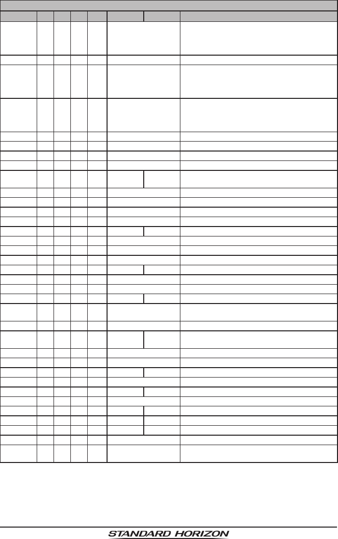
Page 41
HX40
VHF MARINE CHANNEL CHART
CH U C I S/D TX RX CHANNEL USE
71 X X X S 156.575
US, Canada: Non-commercial (Recre-
ational),
International: Port operations and Ship
movement
72 X X X S 156.625 Non-commercial (Inter-ship only)
73 X X X S 156.675
US: Port Operations,
Canada: Commercial shing only,
International: Inter-ship, Port operations
and Ship movement
74 X X X S 156.725
US: Port Operations,
Canada: Commercial shing only,
International: Inter-ship, Port operations
and Ship movement
75 X X X S 156.775 Port Operations (Inter-ship only) (1 W)
76 X X X S 156.825 Port Operations (Inter-ship only) (1 W)
77 X X S 156.875 Port Operations (Inter-ship only) (1 W)
77 X S 156.875 Port Operations (Inter-ship only)
78 X D 156.925 161.525
Public Correspondence (Marine Operator),
Port operation, ship-movement
78A X S 156.925 Non-commercial (Recreational)
1078 X S 156.925 Non-commercial (Recreational)
1078 X S 156.925
2078 X S 161.525
79 X D 156.975 161.575 Port operation and Ship movement
1079 X S 156.975 Commercial
1079 X S 156.975
2079 X S 161.575
80 X D 157.025 161.625 Port operation, ship movement
80A X S 157.025 Commercial
1080 X S 157.025 Commercial
81 X D 157.075 161.675 Port operation, ship movement
1081 X S 157.075 U.S. Government Only -
Environmental protection operations.
81A X S 157.075 Canadian Coast Guard Only
82 X D 157.125 161.725
Public Correspondence (Marine Operator),
Port operation, ship movement
82A X S 157.125 Canadian Coast Guard Only
1082 X S 157.125 U.S. Government Only
83 X D 157.175 161.775 Public Correspondence (Marine Operator)
83A X S 157.175 Canadian Coast Guard Only
83B X - - - 161.775 CMB Service
1083 X S 157.175 U.S. Government Only
84 X X X D 157.225 161.825 Public Correspondence (Marine Operator)
85 X X X D 157.275 161.875 Public Correspondence (Marine Operator)
86 X X X D 157.325 161.925 Public Correspondence (Marine Operator)
87 X X X S 157.375 Port operation, ship movement
88 X X X S 157.425 Port operation, ship movement
Commercial, Inter-ship Only
NOTE: Simplex channels, 3A, 21A, 23A, 61A, 64A, 81A, 82A and 83A CANNOT be lawfully
used by the general public in U.S.A. waters.
ApplicationforFCC/IC
FCCID:K6630623X30IC:511B-30623X30

HX40
Page 42
11. WARRANTY
Marine Products Limited Warranty
PLEASE NOTE
The following “Limited Warranty” is valid for products that have been
purchased in the United States and Canada. For limited Warranty details
outside the United States, contact the dealer in your country.
STANDARD HORIZON (a division of YAESU USA.) warrants, to the origi-
nal purchaser only, each new Marine Communications Product (“Product”)
manufactured and/or supplied by STANDARD HORIZON against defects in
materials and workmanship under normal use and service for a period of
time from the date of purchase as follows:
Fixed Mount and Portable Transceivers
1 year - if purchased before 01/01/91
3 years - if purchased between 01/01/91 and 01/01/94
3 years Waterproof - if purchased after 01/01/94
Loud hailers
1 year - if purchased before 01/01/91
3 years - if purchased after 01/01/91
Associated Chargers
1 year - if purchased before 01/01/91
3 years - if purchased after 01/01/91
Associated Batteries - 1 year. Note: Batteries will be deemed defective
only if storage capacity drops below 80% of rated capacity or if leakage de-
velops.
Associated Accessories - 1 year. Includes: Microphones/Handsets, Exter-
nal Speakers, Antennas, Carrying Accessories, Power Supplies, and Signal-
ing Boards.
To receive warranty service, the purchaser must deliver the Product, trans-
portation and insurance prepaid, to STANDARD HORIZON (a division of
YAESU USA.). Include proof of purchase indicating model. serial number,
and date of purchase. STANDARD HORIZON will return the Product to the
purchaser freight prepaid. Products purchased prior to January 1, 1991 will
bear the STANDARD HORIZON warranty terms in effect prior to that date.
In the event of a defect, malfunction or failure of the Product during the war-
ranty period, STANDARD HORIZON’s liability for any breach of contract or
any breach of express or implied warranties in connection with the sale of
Products shall be limited solely to repair or replacement, at its option, of the
Product or part(s) therein which, upon examination by STANDARD HORI-
ApplicationforFCC/IC
FCCID:K6630623X30IC:511B-30623X30

Page 43
HX40
ZON, appear to be defective or not up to factory specications. STANDARD
HORIZON may, at its option, repair or replace parts or subassemblies with
new or reconditioned parts and subassemblies. Parts thus repaired or re-
placed are warranted for the balance of the original applicable warranty.
STANDARD HORIZON will not warrant installation, maintenance or service
of the Products. In all instances, STANDARD HORIZON’s liability for dam-
ages shall not exceed the purchase price of the defective Product.
This warranty only extends to Products sold within the 50 States of the Unit-
ed States of America and the District of Columbia.
STANDARD HORIZON will pay all labor to repair the product and replace-
ment parts charges incurred in providing the warranty service except where
purchaser abuse or other qualifying exceptions exist. The purchaser must
pay any transportation expenses incurred in returning the Product to STAN-
DARD HORIZON for service.
This limited warranty does not extend to any Product which has been sub-
jected to misuse, neglect, accident, incorrect wiring by anyone other than
STANDARD HORIZON, improper installation, or subjected to use in violation
of instructions furnished by STANDARD HORIZON, nor does this warranty
extend to Products on which the serial number has been removed, defaced,
or changed. STANDARD HORIZON cannot be responsible in any way for
ancillary equipment not furnished by STANDARD HORIZON which is at-
tached to or used in connection with STANDARD HORIZON’s Products, or
for the operation of the Product with any ancillary equipment, and all such
equipment is expressly excluded from this warranty. STANDARD HORIZON
disclaims liability for range, coverage, or operation of the Product and ancil-
lary equipment as a whole under this warranty. STANDARD HORIZON re-
serves the right to make changes or improvements in Products, during sub-
sequent production, without incurring the obligation to install such changes
or improvements on previously manufactured Products.
The implied warranties which the law imposes on the sale of this Product
are expressly LIMITED, in duration, to the time period specified above.
STANDARD HORIZON shall not be liable under any circumstances for con-
sequential damages resulting from the use and operation of this Product,
or from the breach of this LIMITED WARRANTY, any implied warranties,
or any contract with STANDARD HORIZON. IN CONNECTION WITH THE
SALE OF ITS PRODUCTS, STANDARD HORIZON MAKES NO WARRAN-
TIES, EXPRESS OR IMPLIED AS TO THE MERCHANTABILITY OR FIT-
NESS FOR A PARTICULAR PURPOSE OR OTHERWISE, EXCEPT AS
EXPRESSLY SET FORTH HEREIN.
Some states do not allow the exclusion or limitation of incidental or conse-
quential damages, or limitation on how long an implied warranty lasts, so the
above limitations or exclusions may not apply. This warranty gives specic
legal rights, and there may be other rights which may vary from state to state.
ApplicationforFCC/IC
FCCID:K6630623X30IC:511B-30623X30

HX40
Page 44
ONLY PRODUCTS SOLD ON OR AFTER JANUARY 1, 1991 ARE COV-
ERED UNDER THE TERMS OF THIS LIMITED WARRANTY.
ON-LINE WARRANTY REGISTRATION
THANK YOU for buying STANDARD HORIZON (a division of YAESU
USA.) products! We are condent your new radio will serve your needs
for many years!
Please visit www.standardhorizon.com to register the HX40 Marine VHF.
It should be noted that visiting the Web site from time to time may be
benecial to you, as new products are released they will appear on the
STANDARD HORIZON Web site.
Product Support Inquiries
If you have any questions or comments regarding the use of the HX40,
you can visit the STANDARD HORIZON Web site to send an E-mail or
contact the Product Support team at (800) 767-2450 ext 6300 M-F 8:00-
5:00PST.
In addition to the warranty, STANDARD HORIZON includes a lifetime “at
rate” program to provide service after the warranty period has expired. If
you wish to obtain the at rate price for out-of-warranty repair, you must
include the information on the Owner’s Record with the unit when you re-
turn it to your Dealer or to STANDARD HORIZON.
Lifetime Flat Rate Service Program: For the original Owner only, for the
lifetime of the unit, STANDARD HORIZON will repair the unit to original
specications.
Note: The at rate amount is payable by the Owner only if STANDARD
HORIZON or the STANDARD HORIZON Dealer determines that a repair
is needed. After the repair, a 90-day warranty will be in effect from the
date of return of the unit to the Owner.
This service program is not available for equipment which has failed as
a result of neglect, accident, breakage, misuse, improper installation or
modication, or water damage (depending on the product).
ApplicationforFCC/IC
FCCID:K6630623X30IC:511B-30623X30

Page 45
HX40
12. SPECIFICATIONS
Performance specications are nominal, unless otherwise indicated, and are
subject to change without notice.
12.1 GENERAL
Frequency Ranges: TX: 156.025 MHz - 161.600 MHz
RX: 156.050 MHz - 163.275 MHz
(Including WX ch)
Channel Spacing: 25 kHz
Frequency Stability: ±3 ppm
(–4 °F to +140 °F [–20 °C to +60 °C])
Emission Type: 16K0G3E
Antenna Impedance: 50
Operating Voltage: 7.4 V DC, Negative Ground (Battery Terminal)
Current Consumption: 330 mA (Receive, Typical at AF MAX.)
100 mA (Standby)
1.6 A / 1.0 A / 0.7 A (TX: 6 W / 2.5 W / 1 W)
Operating Temperature: –4 °F to +140 °F (–20 °C to +60 °C)
Case Size (W x H x D): 2.05” x 3.74” x 1.3” (52 x 95 x 33 mm)
(w/o knob & antenna)
Weight (Approx.): 8.1 oz (230 g)
(with hand strap, belt clip & antenna)
12.2 TRANSMITTER
RF Power Output: 6 W / 2.5 W / 1 W (@7.4 V )
Maximum Deviation: ±5 kHz
Spurious Emission: Less than 0.25 µW
Microphone Impedance: 2 k
12.3 RECEIVER
Circuit Type: Double Conversion Superheterodyne
Intermediate Frequencies: 1st: 38.85 MHz, 2nd: 450 kHz
Adjacent Channel Selectivity
: 70 dB typical
Intermodulation: 70 dB typical
Hum & Noise Ratio: 40 dB typical
Sensitivity: 0.25 µV for 12 dB SINAD
Selectivity: 12 kHz / 25 kHz (–6 dB / –60 dB)
AF Output (Internal SP): 600 mW @16 for 10 % THD (@7.4 V)
12.4 FM BROADCAST RECEIVER
Frequency Range: 65 MHz - 108 MHz
Frequency Step: 100 kHz
Sensitivity: 1.0 µV for 12 dB SINAD
ApplicationforFCC/IC
FCCID:K6630623X30IC:511B-30623X30

HX40
Page 46
13. FCC AND CANADA RADIO LICENSE INFORMATION
Standard Horizon radios comply with the Federal Communication Commis-
sion (FCC) and the Innovation, Science and Economic Development Canada
(ISED) requirements that regulate the Maritime Radio Service.
MARITIME STATION LICENSE
An FCC ship station license is no longer required for any vessel traveling in
U.S. waters which uses a VHF marine radio, RADAR or EPIRB, and which is
not required to carry radio equipment. However, any vessel required to carry
a marine radio on an international voyage, carrying a HF single side band
radiotelephone or marine satellite terminal. FCC license forms, including ap-
plications for ship (605) and land station licenses can be downloaded via the
Internet at https://www.fcc.gov/fcc-form-605. To obtain a form from the FCC,
call (888) 225-5322.
MARINE RADIO CALL SIGN
Currently the FCC does not require recreational boaters to have a Ship Ra-
dio Station License. The USCG recommends the boats registration number
and the state to be used.
CANADIAN SHIP STATION LICENSING
Please click on the following link for licensing information:
http://www.ic.gc.ca/eic/site/smt-gst.nsf/eng/h_sf01775.html
The following link lists several Branches/Ofces regarding licensing. Licens-
ing depends on the region of operations.
http://www.ic.gc.ca/eic/site/smt-gst.nsf/eng/sf01742.html
FCC / ISED INFORMATION
The following data pertaining to the transceiver is necessary to ll out the
license application.
FCC Type Accepted: ............................................................................. Part 80
Output Power with built-in Battery: .................... 1.0/2.5/6.0 W (Low/Mid/High)
Emission: .......................................................................................... 16K0G3E
Frequency Range: ......................................................156.025 to 162.025MHz
FCC Type Number: .................................................................... K6630623X30
ISED Type Approval: .............................................................. 511B-30623X30
ApplicationforFCC/IC
FCCID:K6630623X30IC:511B-30623X30

Page 47
HX40
14. RF EXPOSURE SAFETY STATEMENT
SAFETY INFORMATION
Your wireless handheld portable transceiver contains a low power transmitter. When the
Push-to-Talk (PTT) button is pushed, the transceiver sends out radio frequency (RF) sig-
nals. In August 1996, the Federal Communications Commission adopted RF exposure
guidelines with safety levels for hand-held wireless devices.
This device is authorized to operate at a duty factor not to exceed 50% (this corresponds
to 50% transmission time and 50% reception time).
WARNING: To maintain compliance with the FCC’s RF exposure guidelines, this trans-
mitter and its antenna must maintain a separation distance of at least 1 inch (2.5 centime-
ters) from your face. Speak in a normal voice, with the antenna pointed up and away from
the face at the required separation distance.
Use only the supplied antenna. Unauthorized antennas, modications, or attachments
could damage the transmitter, and may violate FCC regulations.
CONSIGNES DE SECURITE
Votre émetteur-récepteur portatif sans lcontient un émetteur à faible puissance. Lorsque
vous appuyez sur le bouton Push-to-Talk (PTT), l’émetteur-récepteur émet des signaux
de radiofréquence (RF). En août 1996, la FCC (Commission Fédérale des Communica-
tions) a adopté des directives relatives à l’exposition aux RF avec des niveaux de sécurité
pour les appareils sans l portatifs. Le fonctionnement de cet appareil est autorisé à un
facteur d’utilisation ne dépassant pas 50 % (correspondant à 50% de la durée de trans-
mission et 50% de la durée de réception).
AVERTISSEMENT: Pour assurer la conformité avec les directives d’exposition RF de la
FCC, cet émetteur-récepteur et son antenne doivent être maintenus à une distance mi-
nimum d’un pouce (2,5 centimètre) de votre visage. Parlez avec une voix normale, avec
l’antenne dirigée vers le haut et éloignée du visage, à la distance requise. Si vous utilisez
un casque pour cette radio, et que vous portez la radio sur vous, utilisez exclusivement
le clip de ceinture Yaesu pour cet émetteur-récepteur, et assurez-vous que l’antenne se
trouve à une distance minimum d’un pouce (2,5 centimètres) de votre corps pendant
l’émission. Utilisez exclusivement l’antenne fournie. Les antennes, les modicationsou les
accessoires non autorisés peuvent endommager l’émetteur-récepteur et enfreindre les
réglementations FCC.
15. FCC NOTICE
NOTICE
Unauthorized changes or modications to this equipment may void compliance with FCC
Rules. Any change or modication must be approved in writing by STANDARD HORIZON,
a division of YAESU USA.
THIS DEVICE COMPLIES WITH PART 15 OF THE FCC RULES. OPERATION IS SUB-
JECT TO THE FOLLOWING TWO CONDITIONS: (1) THIS DEVICE MAY NOT CAUSE
HARMFUL INTERFERENCE, AND (2) THIS DEVICE MUST ACCEPT ANY INTERFER-
ENCE RECEIVED, INCLUDING INTERFERENCE THAT MAY CAUSE UNDESIRED OP-
ERATION.
ApplicationforFCC/IC
FCCID:K6630623X30IC:511B-30623X30

HX40
Page 48
NOTE: THE GRANTEE IS NOT RESPONSIBLE FOR ANY CHANGES OR MODIFICA-
TIONS NOT EXPRESSLY APPROVED BY THE PARTY RESPONSIBLE FOR COMPLI-
ANCE. SUCH MODIFICATIONS COULD VOID THE USER’S AUTHORITY TO OPERATE
THE EQUIPMENT.
NOTE: This equipment has been tested and found to comply with the limits for a Class B
digital device, pursuant to part 15 of the FCC Rules. These limits are designed to provide
reasonable protection against harmful interference in a residential installation. This equip-
ment generates uses and can radiate radio frequency energy and, if not installed and used
in accordance with the instructions, may cause harmful interference to radio communica-
tions. However, there is no guarantee that interference will not occur in a particular instal-
lation. If this equipment does cause harmful interference to radio or television reception,
which can be determined by turning the equipment off and on, the user is encouraged to try
to correct the interference by one or more of the following measures:
Reorient or relocate the receiving antenna.
Increase the separation between the equipment and receiver.
Connect the equipment into an outlet on a circuit different from that to which the receiver
is connected.
Consult the dealer or an experienced radio/TV technician for help.
This device complies with Industry Canada license-exempt RSS standard(s). Operation is
subject to the following two conditions: (1) this device may not cause interference, and (2)
this device must accept any interference, including interference that may cause undesired
operation of the device.
Le présent appareil est conforme aux CNR d’Industry Canada applicables aux appareils ra-
dio exempts de licence. L’exploitation est autorisée aux deux conditions suivantes : (1) l’ap-
pareil ne doit pas produire de brouillage, et (2) l’utilisateur de l’appareil doit accepter tout
brouillage radioélectrique subi, même si le brouillage est susceptible d’en compromettre le
fonctionnement.
The applicant is responsible for providing proper instructions to the user of the radio device,
and any usage restrictions, including limits of exposure durations. The user manual shall
provide installation and operation instructions, as well as any special usage conditions, to
ensure compliance with SAR and/or RF eld strength limits. For instance, compliance dis-
tance shall be clearly stated in the user manual.
The user manual of devices intended for controlled use shall also include information re-
lating to the operating characteristics of the device; the operating instructions to ensure
compliance with SAR and/or RF eld strength limits; information on the installation and op-
eration of accessories to ensure compliance with SAR and/or RF eld strength limits; and
contact information where the user can obtain Canadian information on RF exposure and
compliance. Other related information may also be included.
ApplicationforFCC/IC
FCCID:K6630623X30IC:511B-30623X30
ApplicationforFCC/IC
FCCID:K6630623X30IC:511B-30623X30

1801M-CC
Printed in China
Copyright 2018
YAESU MUSEN CO., LTD.
All rights reserved.
No portion of this manual may be
reproduced without the permission of
YAESU MUSEN CO., LTD.
YAESU U.S.A.
6125 Phyllis Drive, Cypress, California 90630
www.standardhorizon.com
*EM061N102*
EM061N102
ApplicationforFCC/IC
FCCID:K6630623X30IC:511B-30623X30