Yaesu Musen 50023X20 AIR BAND HT RADIO User Manual 1
Yaesu Musen Co., Ltd. AIR BAND HT RADIO 1
UserManual.wiki
>
Yaesu Musen
>
50023X20 User Manual
>
User Manual 1
Contents
1.
User Manual 1
2.
User Manual 2
User Manual 1
Navigation menu
Upload a User Manual
Namespaces
Wiki Guide
HTML
PDF
Info
Views
User Manual
Discussion / Help
Navigation

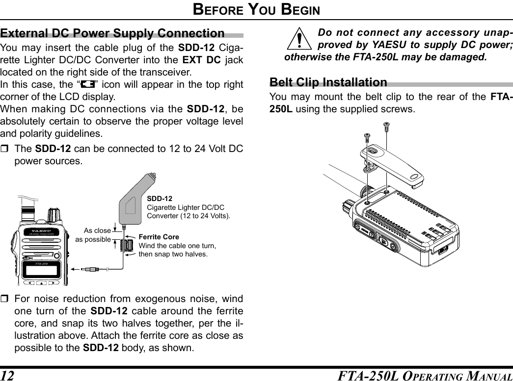
![FTA-250L OperATing MAnuAL14Turning the power on and off1. Rotate the PWR/VOL knob out of the click-stop to turn the transceiver ON.2. To turn the transceiver OFF, turn the PWR/VOL knob fully counter-clock-wise into the click-stop po-sition. The “ ” icon appears on the display when the audio signal is received on the current frequency.Adjusting the volume1. Rotate the PWR/VOL knob to adjust the receiver vol-ume.Adjusting the squelch1. Press the SQL key, then press the [◄] or [►] key to adjust to a squelch level (OFF to 15) at which the background noise is muted.2. Press the SQL key to save the squelch setting and return to normal op-eration.BasIC operatIon](https://usermanual.wiki/Yaesu-Musen/50023X20.User-Manual-1/User-Guide-3372076-Page-16.png)
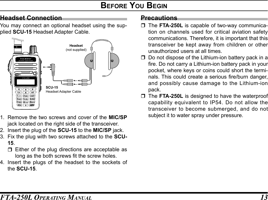
![FTA-250L OperATing MAnuAL 1515BasIC operatIonMonitor SwitchWhen listening to a very weak signal from an aircraft or ground station, you may observe the signal disap-pearing periodically as the incoming signal strength becomes too weak to override the squelch threshold setting.To disable the squelch temporarily;1. press and hold the SQL key for 1 second. The squelch will remain open and you should have a better chance of hearing weak signals.2. To return to normal opera-tion, press the SQL key momentarily.Adjusting the frequency Pressing the [►] tunes the FTA-250L toward a higher frequency, while pressing the [◄] will lower the operating frequency, in steps pre-programmed for the cur-rent operating band. Directly entering fre-quencies from the keypad is the easiest method if you know the frequency on which you wish to operate. Just enter the five digits of the frequency to move to that frequency. For example, to set 134.35 MHz, press [1] à [3] à [4] à [3] à [5]. To set 118.275 MHz, you do not need to press the nal “5” in the frequency as below: [1] à [1] à [8] à [2] à [7].](https://usermanual.wiki/Yaesu-Musen/50023X20.User-Manual-1/User-Guide-3372076-Page-17.png)
![FTA-250L OperATing MAnuAL1616BasIC operatIonAccessing the 121.5 MHz Emergency FrequencyThe FTA-250L can quickly access the 121.500 MHz emergency frequency. This function can be activated even when the keypad lock function (described on page 25) is in use.1. Press and hold the [121.5] key. After four beeps, the transceiver enters the emergency mode and the frequency is automatically tuned to 121.500 MHz.2. To exit the emergency mode, press the [CLR] key. The message confirm-ing the cancelation of the emergency mode will ap-pear.3. Press the [◄] key to se-lect “YES”, then press the [ENT] key.Transmission1. Press and hold the PTT switch. The “ ” icon will ap-pear on the display during transmission.2. Speak into the microphone area on the front panel of the radio in a normal voice level.3. To return to the receive mode, release the PTT switch.Resetting the TransceiverTo clear all memories and other settings to factory de-faults:1. Turn the transceiver OFF.2. Press and hold the [CLR] key and [ENT] key while turning the transceiver ON.3. When the LCD backlight comes on, release the [CLR] key and [ENT] key, to reset all settings to their factory defaults.](https://usermanual.wiki/Yaesu-Musen/50023X20.User-Manual-1/User-Guide-3372076-Page-18.png)
![FTA-250L OperATing MAnuAL 1717BasIC operatIonOperation ModesThe FTA-250L operate in the modes listed below. You can switch the modes via the MENU screen displayed by pressing the [MENU] key on the front panel.When turning on the FTA-250L, the last mode you have used before turning off will automatically be en-tered.COMMThe basic operating mode for communi-cation.MEMORYThis mode provides you with the ability to store and recall as many as 250 channels in the transceiver’s main memory bank.WX CH (WEATHER) (USA/Canada Only)This mode allows you to receive NOAA weather channel broadcasts. The 10 weather channels are pre-programmed at the factory.SETUPThis mode allows certain aspects of your radio’s conguration to be customized for your personal operating conditions.](https://usermanual.wiki/Yaesu-Musen/50023X20.User-Manual-1/User-Guide-3372076-Page-19.png)
![FTA-250L OperATing MAnuAL1818BasIC operatIonBASIC OPERATION OF THE MENU MODEUsing the menu mode, the various functions of the FTA-250L can be customized to match the method of use. You can select the items that you would like to adjust from the respective lists and enter or select the appropriate settings for the intended various opera-tion.1. Press the [MENU] key.2. Select “SETUP” by press-ing the [◄] or [►] key.3. Press the [ENT] key.4. Select the desired menu item by pressing the [▲] or [▼] key, and then press the [ENT] key.5. Select the desired item by pressing the [▲] or [▼] key, and then press the [ENT] key.6. Select the desired setting by pressing the [◄] or [►] key.7. Press the [ENT] key to store the selected setting.8. Press the PTT switch to return to normal opera-tion.The same operation process as the above is writ-ten as follows in this operation manual.[MENU] à “SETUP” à “CONFIG” à “KEY BEEP”](https://usermanual.wiki/Yaesu-Musen/50023X20.User-Manual-1/User-Guide-3372076-Page-20.png)
![FTA-250L OperATing MAnuAL 19Pitch ControlThe FTA-250L includes a feature that lets you choose four specific receiver audio responses to allow the most comfortable and/or effective reception in noisy environments. The effect is similar to that provided by an “Equalizer” in a stereo.1. [MENU] à “SETUP” à “COM SETUP” à “AF PITCH CONT”.2. Select the receiver audio response by pressing the [◄] or [►] key, and then press the [ENT] key.The setting changes in the following order.NORMAL: The received audio signal does not pass through the equalizer circuit.LO CUT: The received audio is passed without roll-off on the low end.HI CUT: The received audio is passed without roll-off on the high end.HI & LO CUT: The received audio is passed without roll-off on the high and low ends.Tip: The default setting: NORMAL3. Press the PTT switch to return to normal opera-tion.Flip-Flop Feature (Frequency Recall)The FTA-250L can memorize up to 9 operating fre-quencies automatically, and recall them for later use.Up to 9 frequencies may be memorized. Once all 9 memories have been programmed, previous frequen-cies will be over-written, on a rst-in, rst-out basis.Recall Frequency1. Press the [▲] key. You will see the previ-ously selected recall number appearing on the LCD.2. Press the [▲] or [▼] key to select previously stored frequencies.1 àà 2 àà 3 à ..... à 7 àà 8 àà 9advanCed operatIon](https://usermanual.wiki/Yaesu-Musen/50023X20.User-Manual-1/User-Guide-3372076-Page-21.png)
![FTA-250L OperATing MAnuAL2020advanCed operatIonWeather alert receptionIn the event of extreme weather disturbances, such as storms and hurricanes, the NOAA (National Oce-anic and Atmospheric Administration) sends a weath-er alert accompanied by a 1050 Hz tone and subse-quent weather report on one of the NOAA weather channels.When the transceiver receives the weather alert on the op-erating frequency, it displays a warning as below on the screen and continues to make alarm sounds until either of the keys is pressed.You may enable or disable the alarm function when receiving the weather alert signal via the COMM SET-UP menu. See page 35 for details.Reception of Weather Channel Broadcasts- Weather Channels for USA/ Canada only -The FTA-250L can receive VHF weather channel broadcasts, which may assist your flight planning. The FTA-250L includes a special bank capable of storing 10 weather channels, which simplies access when you are in an unfamiliar location.1. Press the [MENU] key.2. Select “WX CH” by press-ing the [◄] or [►] key, and then press the [ENT] key. The last channel you have tuned will be received.3. You can also select a weather channel from the pre-programmed list with the [▲] or [▼] key.4. To exit the WX mode, press the [MENU] key, se-lect the mode other than “WX CH” by pressing the [◄] or [►] key, and then press the [ENT] key.](https://usermanual.wiki/Yaesu-Musen/50023X20.User-Manual-1/User-Guide-3372076-Page-22.png)
![FTA-250L OperATing MAnuAL 2121advanCed operatIonDual Watch OperationThe dual watch feature automatically checks for ac-tivity on the P-ch (priority channel) set via the PRI-ORITY-CH menu while you are operating on another channel. During the dual watch operation, the current channel and the P-ch will be polled alternately for a 200 ms interval.Setting the P-ch1. [MENU] à “SETUP” à “PRIORITY CH”.2. Enter the frequency you want to poll, with the key-pad.3. Select “FINISH” by press-ing the [◄] or [►] key, and then press the [ENT] key.4. Press the PTT switch to return to normal opera-tion.Starting the dual watch1. Press the [FUNC] key.2. Select “DUAL WATCH” by pressing the [◄] or [►] key, and then press the [ENT] key. The display will return to the previous screen and the “DW” icon will be dis-played, indicating the FTA-250L is in dual watch. When the transceiver encounters a signal on the current channel, the radio polls both channels al-ternately with longer staying time on the current channel. When the transceiver encounters a signal in the P-ch, the transceiver stays on the P-ch until the signal disappears, and the frequency indication on the display blinks. After the signal disappears, the dual watch re-sumes.3. To stop the dual watch, repeat steps 1 and 2 above.](https://usermanual.wiki/Yaesu-Musen/50023X20.User-Manual-1/User-Guide-3372076-Page-23.png)
![FTA-250L OperATing MAnuAL2222advanCed operatIonNoise CancellationTo cancel background noise when transmitting and receiving.Enables/disables the Noise-canceling function of the transmitter and receiver independently.1. [MENU] à “SETUP” à “COMM SETUP” à “NOISE CANCEL”.2. Select “TX MODE” b y pressing the [◄] or [►] key, and then press the [ENT] key.3. Press the [◄] or [►] key to select “ON” or “OFF”, and then press the [ENT] key.4. Select “RX MODE” by pressing the [◄] or [►] key, and then press the [ENT] key.5. Select the noise level from “LV 1” through “MAX” or “OFF” by pressing the [◄] or [►] key, and then press the [ENT] key.6. Press the PTT switch to return to normal opera-tion.TOT FeatureThe TOT (time-out timer) shuts off the transceiver af-ter continuous transmission exceeds the programmed time. This feature prevents unintended transmission by mistake and reduces battery consumption.1. [MENU] à “SETUP” à “COMM SETUP” à “TX TOT”.2. Select the desired TOT time by pressing the [◄] or [►] key, and then press the [ENT] key.The setting changes in the following order.1 àà 2 àà 3 àà 4 àà 5 (MIN)Tip: The default setting: 5 MIN3. Press the PTT switch to return to normal opera-tion.](https://usermanual.wiki/Yaesu-Musen/50023X20.User-Manual-1/User-Guide-3372076-Page-24.png)
![FTA-250L OperATing MAnuAL 2323advanCed operatIonBattery Saver during ReceptionOne of the important features of the FTA-250L is its battery saver, which “puts the transceiver to sleep” for a time interval, periodically “waking it up” to check for activity. If somebody is talking on the channel, the FTA-250L will remain in the “awake” mode, then resume its “sleep” cycles. This feature significantly reduces battery drain.1. [MENU] à “SETUP” à “CONFIG” à “BATTERY SAVE”.2. Select the desired interval time by pressing the [◄] or [►] key, and then press the [ENT] key.OFF : Disables this function.50 % : Sleeps for 100 ms after 100 ms awake70 % : Sleeps for 250 ms after 100 ms awake80 % : Sleeps for 450 ms after 100 ms awake90 % : Sleeps for 900 ms after 100 ms awakeTip: The default setting: 50 %3. Press the PTT switch to return to normal opera-tion.Using the Headset MicrophoneIf you want to use the microphone of an aviation headset, change the assignment of microphone con-trolled with the PTT switch.1. [MENU] à “SETUP” à “COMM SETUP” à “MIC SELECT”.2. Select “EXTERNAL” by pressing the [◄] or [►] key, and then press the [ENT] key.3. Press the PTT switch to return to normal opera-tion.When an optional aviation headset is connected, the PTT switch on the transceiver will activate the head-set microphone for transmission.Note: If you nd it difcult to use the PTT switch of the transceiver, we recommend to use an after-market external PTT switch.](https://usermanual.wiki/Yaesu-Musen/50023X20.User-Manual-1/User-Guide-3372076-Page-25.png)
![FTA-250L OperATing MAnuAL2424advanCed operatIonVOX OperationIf you want to have both hands free, use a headset and activate the VOX (voice-actuated transmit/receive switching) system.Notes: The VOX system does not work when us-ing just the internal microphone; an exter-nal headset must be used. Do not activate the VOX system when con-necting the optional microphone SSM-10A.1. [MENU] à “SETUP” à “COMM SETUP” à “VOX”.2. Select “ON” or “OFF” by pressing the [◄] or [►] key, and then press the [ENT] key.3. Press the PTT switch to return to normal operation. The “V” icon, which indi-cates that the VOX system is active. To adjust the VOX gain, select one of the follow-ing gain levels on the item “VOX LEVEL” of the COMM SETUP menu in the SETUP mode.MIN / LV1 / LV2 / LV3 / MAX To set the VOX delay, select one of the following times on the item “VOX DELAY” of the COMM SETUP menu in the SETUP mode.0.5 / 1.0 / 1.5 / 2.0 / 3.0 (SEC)](https://usermanual.wiki/Yaesu-Musen/50023X20.User-Manual-1/User-Guide-3372076-Page-26.png)
![FTA-250L OperATing MAnuAL 2525advanCed operatIonSide Tone ControlWhen utilizing an external headset, you may moni-tor your own voice when talking into the microphone through the headphones.Note: Do not activate the side tone function when connecting the optional microphone SSM-10A.1. [MENU] à “SETUP” à “COMM SETUP” à “SIDE TONE”.2. Select the side tone level by pressing the [◄] or [►] key, and then press the [ENT] key.The setting changes in the following order.OFF / LV 1 / LV 2 / LV 3 / MAX3. Press the PTT switch to return to normal opera-tion. To change the side tone level temporarily during the monitoring, pressing the [▲], [▼], [◄] or [►] key when pressing and holding the PTT switch.Lock FunctionThis function prevents accidental changes to the fre-quency setting and the keypad controls.1. Press and hold the LOCK key. While the FTA-250L is locked, the controls with the keys except the PTT switch, SQL key, LOCK key, the PWR/VOL knob, and the [121.5] key are dis-abled. If any of the keys is pressed, either of “KEY LOCK” will appear on the screen for 2 seconds and then the display will return to the previous screen.2. To turn the lock feature off, press and hold the LOCK key again. “UNLOCK” will appear on the screen for 2 sec-onds and then the display will return to the previ-ous screen.](https://usermanual.wiki/Yaesu-Musen/50023X20.User-Manual-1/User-Guide-3372076-Page-27.png)
![FTA-250L OperATing MAnuAL2626advanCed operatIonPTT Lock FunctionThis function prevents accidental transmissions by locking or disabling the PTT switch.Turning lock/unlock the PTT lock functionYou may enable or disable the PTT lock function.1. [MENU] à “SETUP” à “CONFIG” à “PTT LOCK”.2. Select “ON” or “OFF” by pressing the [▲] or [▼] key, and then press the [ENT] key.3. Press the PTT switch to return to normal opera-tion.ANL FeatureFor reduction of impulse noise, such as that produced by an engine’s ignition system, the ANL (automatic noise limiter) feature may prove helpful.1. [MENU] à “SETUP” à “COMM SETUP” à “ANL”.2. Select “ON” or “OFF” by pressing the [▲] or [▼] key, and then press the [ENT] key.3. Press the PTT switch to return to normal operation. The “ANL” icon, which indicates that the ANL sys-tem is active.](https://usermanual.wiki/Yaesu-Musen/50023X20.User-Manual-1/User-Guide-3372076-Page-28.png)
![FTA-250L OperATing MAnuAL 2727advanCed operatIonChanging the Channel StepsThe synthesizer of the FTA-250L provides the option of utilizing 8.33*/25 kHz channel steps.* 8.33 kHz; Europe only1. [MENU] à “SETUP” à “COMM SETUP” à “FREQ STEP”.2. Select “25KHZ” o r “8.33KHZ” by pressing the [▲] or [▼] key, and then press the [ENT] key.3. Press the PTT switch to return to normal opera-tion.Note: When you set the channel step to 8.33 kHz, the channel display differs from actual operat-ing frequency; see the chart below. However, the operator (pilot, tower, control, etc.) will call out the frequency according to what the display indicates.Operating FrequencyDisplay8.33 kHz Step 25 kHz Step1**.0000 MHz 1**.005 1**.0001**.0083 MHz 1**.0101**.0166 MHz 1**.0151**.0250 MHz 1**.030 1**.0251**.0333 MHz 1**.0351**.0416 MHz 1**.0401**.0500 MHz 1**.055 1**.0501**.0583 MHz 1**.0601**.0666 MHz 1**.0651**.0750 MHz 1**.080 1**.0751**.0833 MHz 1**.0851**.0916 MHz 1**.090 The adjacent channel selectivity will be slightly degraded while receiving using 8.33 kHz channel steps.](https://usermanual.wiki/Yaesu-Musen/50023X20.User-Manual-1/User-Guide-3372076-Page-29.png)