Yaesu Musen 50023X20 AIR BAND HT RADIO User Manual 1
Yaesu Musen Co., Ltd. AIR BAND HT RADIO 1
Contents
- 1. User Manual 1
- 2. User Manual 2
User Manual 1
Operating Manual
AIR BAND TRANSCEIVER
FTA-250L

Contents
Important Notice! ............................................................... 1
Introduction ........................................................................2
Accessories and Options .................................................3
Supplied Accessories ............................................................. 3
Available Options ................................................................... 3
Safety Precautions ............................................................4
Controls & Connectors (Top / Front Panel) .....................7
Controls & Connectors (Left / Right Side) ......................8
Controls & Connectors (LCD) ..........................................9
Before You Begin .............................................................10
Antenna Installation.............................................................. 10
Installing the Battery Pack.................................................... 10
Removing the Battery Pack.................................................. 10
Battery Charging .................................................................. 10
Low Battery Indication ...........................................................11
External DC Power Supply Connection ............................... 12
Belt Clip Installation.............................................................. 12
Headset Connection............................................................. 13
Precautions .......................................................................... 13
Basic Operation ...............................................................14
Turning the power on and off ............................................... 14
Adjusting the squelch ........................................................... 14
Monitor Switch...................................................................... 15
Adjusting the frequency........................................................ 15
Accessing the 121.5 MHz Emergency Frequency ............... 16
Transmission ........................................................................ 16
Resetting the Transceiver .................................................... 16
Operation Modes.................................................................. 17
BASIC OPERATION OF THE MENU MODE ....................... 18
Advanced Operation .......................................................19
Pitch Control......................................................................... 19
Flip-Flop Feature (Frequency Recall) .................................. 19
Reception of Weather Channel Broadcasts ......................... 20
Weather alert reception ........................................................ 20
Dual Watch Operation .......................................................... 21
Setting the P-ch.................................................................... 21
Starting the dual watch......................................................... 21
Noise Cancellation ............................................................... 22
TOT Feature ......................................................................... 22
Battery Saver during Reception ........................................... 23
Using the Headset Microphone ............................................ 23
VOX Operation ..................................................................... 24
Side Tone Control ................................................................. 25
Lock Function ....................................................................... 25
PTT Lock Function ............................................................... 26
ANL Feature ......................................................................... 26
Changing the Channel Steps ............................................... 27
Function Modes.................................................................... 28
Memory Operation ........................................................... 29
Recalling the Memories........................................................ 29
Instant Storage ..................................................................... 30
Maintenance of the Memory................................................. 30
Scanning Operation ........................................................32
Scanning Channels .............................................................. 32
Scanning the Specied Channels ........................................ 33
SETUP Mode ....................................................................34
Basic Operation.................................................................... 34
Maintenance of the Memory................................................. 35
Setting of the COMM SETUP Mode Operation .................... 35
PRIORITY CH ...................................................................... 37
Setting of the Operation and ................................................ 37
Conguration of the Transceiver ......................................... 37
About the Transceiver .......................................................... 38
Summary of the SETUP Menu ............................................. 39
Specications ..................................................................41
Troubleshooting For Headset Connection .................... 42
FTA-250L OperATing MAnuAL 1
Important notICe!
FCC RF Exposure Compliance Requirements for Occupational Use Only:
The FTA-250L has been tested and complies with the Federal Communications Commission (FCC) RF exposure limits
for Occupational Use/Controlled Exposure Environment. In addition, the radio complies with the following Standards
and Guidelines:
FCC 96-326, Guidelines for Evaluating the Environmental Effects of Radio-Frequency Radiation.
FCC OET Bulletin 65 Edition 97-01 (1997) Supplement C, Evaluating Compliance with FCC Guidelines for Human
Exposure to Radio Frequency Electromagnetic Fields.
ANSI/IEEE C95.1-1992, IEEE Standard for Safety Levels with Respect to Human Exposure to Radio Frequency
Electromagnetic Fields, 3 kHz to 300 GHz.
ANSI/IEEE C95.3-1992, IEEE Recommended Practice for the Measurement of Potentially Hazardous Electromag-
netic Fields - RF and Microwave.
This radio is NOT approved for use by the general population in an uncontrolled environment. This radio is
restricted to occupational use, work related operations only where the radio operator must have the knowl-
edge to control its RF exposure conditions.
When transmitting, hold the radio in a vertical position with its microphone 1 to 2 inches (2.5 to 5 cm) away
from your mouth and keep the antenna at least 1 inch (2.5 cm) away from your head and body.
The radio must be used with a maximum operating duty cycle not exceeding 50%, in typical Push-to-Talk
congurations. DO NOT transmit for more than 50% of total radio use time (50% duty cycle). Transmitting
more than 50% of the time can cause FCC RF exposure compliance requirements to be exceeded.
The radio is transmitting when the “” icon is displayed on the upper left corner of the screen of the ra-
dio. You can cause the radio to transmit by pressing the PTT button.
Always use YAESU authorized accessories.
NOTICE
There are no user-serviceable points inside this transceiver.
All service jobs must be referred to your Authorized Service Center.

FTA-250L OperATing MAnuAL2
IntroduCtIon
The YAESU FTA-250L is ultra compact, stylish, solid hand-held transceivers providing communication (transmit
and receive) capability on the International Aircraft Communication Band (“COM” band: 118 to 136.975 MHz).
The FTA-250L includes NOAA weather band monitoring and 250 memory channels. The channel congurations
can be easily reprogrammed in minutes using the optional PC Programming Software and your PC.
We recommend that you read this manual in its entirety, so as to understand the many features of the FTA-250L
completely. Keep this manual handy, so you may use it for reference.
Congratulations!
You now have at your ngertips a valuable communications tool, a YAESU two-way radio! Rugged, reliable
and easy to use, your YAESU radio will keep you in constant touch with your friends and colleagues for
years to come, with negligible maintenance or down-time.
Please take a few minutes to read this manual carefully. The information presented here will allow you to
derive maximum performance from your radio, in case questions arise later on.
We’re glad you joined the YAESU team. YAESU products cover the entire spectrum of radio communica-
tions applications, and our worldwide support network is here to serve you. Let us help you get your mes-
sage across.

FTA-250L OperATing MAnuAL 3
aCCessorIes and optIons
Supplied Accessories
Lithium-ion Battery Pack SBR-25LI
AC Adapter SAD-20
Charger Cradle SBH-22
Cigarette Lighter DC/DC Converter SDD-12
Helical Antenna SRA-18A*
or
YHA-73
Headset Adapter Cable SCU-15
Belt Clip SHB-18
Ferrite Core L9190192
Operating Manual
Warranty Card
* Antenna gain: 2.15 dBi
Impedance: 50 ohms
Available Options
Speaker Microphone SSM-10A
Earphone (available only with the SSM-10A)
SEP-10A
Earphone SEP-11A
Li-Ion Battery Pack (7.4 V, 1,950 mAh) SBR-25LI
Li-Ion Battery Pack (7.4 V, 2,500 mAh) SBR-26LI
AC Adapter SAD-20
Charger Cradle SBH-22
Cigarette Lighter DC/DC Converter SDD-12
Helical Antenna SRA-18A
Belt Clip SHB-18
Headset Adapter Cable SCU-15
USB Programming and Control Cable USB-57B
Availability of accessories may vary. Some accesso-
ries are supplied as standard per local requirements,
while others may be unavailable in some regions.
Consult your YAESU Dealer for details regarding
these and any newly-available options.
Connection of any non-YAESU-approved accessory,
should it cause damage, may void the Limited War-
ranty for the FTA-250L.
FTA-250L OperATing MAnuAL4
safety preCautIons
Be sure to read the safety precautions to use this product safely.
Yaesu is not liable for failures and other problems caused due to misuse or use of this product by you or a third
party. Also, Yaesu is not liable for damages caused through use of this product by you or a third party except in
the case where ordered to pay for damages under the laws.
Type and meaning of the marks
DANGER Indicates an imminently hazardous situation
which, if not avoided, could result in death
or serious injury.
WARNING Indicates a potentially hazardous situation
which, if not avoided, could result in death
or serious injury.
CAUTION Indicates a potentially hazardous situation
which, if not avoided, may result in minor or
moderate injury or only property damage.
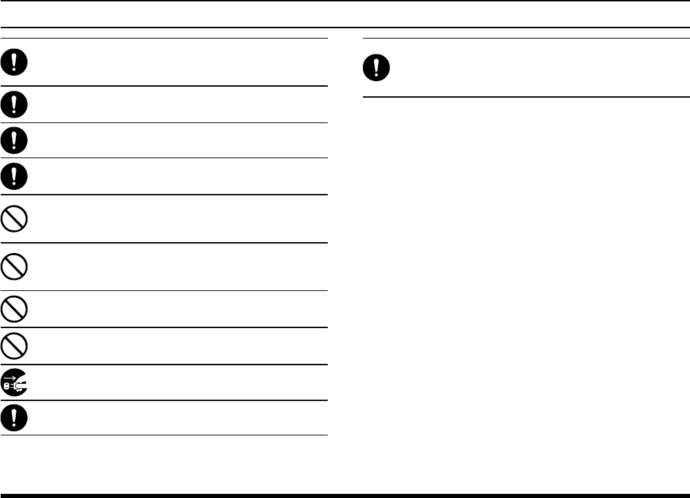
Type and meaning of symbols
Indicates a prohibited action, not to be done in order to use
this product safely. For example, indicates that the prod-
uct should not be disassembled.
Indicates a required action, to be done in order to use this
product safely. For example, indicates that the power
plug should be re-moved.
DANGER
Do not use this product in “an area where use of it is
prohibited”, e.g., inside the hospital or train.”
This product can affect electronic or medical devices.
Do not use this product while riding a bicycle or driving
a car. Accidents can result.
Be sure to stop the bicycle or car at a safe place before us-
ing this product.
Do not perform transmission in a crowded place for the
safety of persons using a medical device such as a car-
diac pacemaker.
The radio wave emitted from this product can cause the
medical device to malfunction and result in an accident.
Do not touch any material leaking from the battery pack
with bare hands.
The chemical that has stuck to your skin or entered your
eye can cause chemical burns. In such a case, consult the
doctor immediately.
Those who are carrying a medical device such as a car-
diac pacemaker should not perform transmission near
the device. When transmitting, use an external antenna
and keep as far as possible away from the external an-
tenna.
The radio wave emitted by the transmitter can cause the
medical device to malfunction and result in an accident.
Do not use this product or the battery charger in a place
where inammable gas is generated.
A re or explosion can occur.
Do not solder or short-circuit the terminal of the battery
pack.
A re, leak, overheating, explosion, or ignition can result. Do
not carry the battery pack together with a necklace, hair pin,
or small metal objects. A short circuit can result.
WARNING
Do not power this transceiver with a voltage other than
the specied power supply voltage.
A re, electric shock, or damage may result.
FTA-250L OperATing MAnuAL 55
safety preCautIons
Do not use the battery pack for any model other than
the specied transceiver.
A re, leak, overheating, explosion, or ignition can result.
Do not make very long transmissions.
The main body of the transceiver may overheat, resulting in
a failure or burns.
Do not disassemble or make any alteration to this prod-
uct.
An injury, electric shock, or failure can result.
Keep the terminals of the battery pack clean.
If terminal contacts are dirty or corroded, a re, leak, over-
heating, explosion, or ignition can result.
Do not handle the battery pack or charger with wet
hands. Do not insert or remove the power plug with wet
hands.
An injury, leak, re, or failure can result.
If smoke or strange odor is emitted from the main body,
battery pack, or battery charger, immediately turn the
transceiver off; remove the battery pack, and remove
the power plug from the outlet.
A fire, leak, overheating, damage, ignition, or failure can
result. Contact the dealer from which you purchased this
product or Yaesu Customer Support.
Do not use the battery pack which is externally dam-
aged or deformed.
A re, leak, heating, explosion, or ignition can result.
Do not use any battery charger which is not specied
by Yaesu.
A re or failure can result.
When transmitting, keep the transceiver at least 5.0 mm
(3/16 inch) away from your body. Use only the supplied an-
tenna. Do not use modied or damaged antennas.
If charging of the battery pack cannot be completed
within the specied charging time, immediately remove
the power plug of the battery charger from the outlet.
A re, leak, overheating, explosion, or ignition can result.
CAUTION
Do not dangle or throw this product by holding its an-
tenna.
This product can hit and injure someone. In addition, doing
so can result in a transceiver failure or damage.
Do not use transceiver in a crowded place.
The antenna can hit someone, resulting in an injury.
Do not place this transceiver in a place subject to direct
sun-light or near a heater.
The transceiver can deform or discolor.
Do not place this transceiver in a humid or dusty place.
A re or failure can result.
During transmission, keep the antenna as far from you
as possible.
Long-time exposure to electromagnetic waves can have a
negative impact on your health.
Do not clean the case with thinner or benzene.
Use a soft, dry cloth to clean the case.
If the transceiver is not being used for an extended period,
turn it off and remove the battery pack for safety.
Do not drop, strike, or throw the transceiver.
A failure or damage may result.
Keep magnetic cards and video tape away from the
transceiver.
The data recorded on cash cards or video tape can be
erased.
Charge the battery pack within the temperature range
from +5 °C to +35 °C (+41 °F to +95 °F).
Charging the battery pack outside this temperature range
can cause leak, overheating, decrease in performance, or
reduction in service life can result.
FTA-250L OperATing MAnuAL66
safety preCautIons
When unplugging the power cord of the battery charger,
be sure to hold the power plug.
Pulling the power cord can dam-age it and cause a re or
electronic shock.
Do not use the earphones or head-phones at an ex-
tremely high volume level.
Hearing impairment can result.
Keep this product out of reach of children.
An injury, etc. can result.
Install the belt clip securely.
If they are installed improperly, the FTA-250L may fall or
drop, resulting in an injury or damage.
Do not place a heavy object on the power cord of the
battery charger.
The battery cord can be dam-aged, resulting in a fire or
electric shock.
Do not use the included battery charger to charge any
battery pack which is not specified for use with the
charger.
A re can result.
Do not operate the transmitter near the TV or radio.
Radio disturbance can occur in the transceiver, the TV, or
the radio.
Do not use any products other than the specied op-
tions and accessories.
A failure can result.
When the battery charger is not in use, remove its pow-
er plug from the outlet.
Before discarding the worn battery pack, afx tape or
the like to its terminals.
Before using this transceiver in a hybrid or fuel-saving car,
be sure to check with the auto-mobile manufacturer regard-
ing use of the transceiver in that car.
Noise generated by an onboard electrical device (inverter,
etc.) can disrupt the normal operation of the transceiver.
FTA-250L OperATing MAnuAL 7
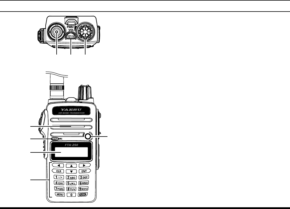
À Antenna Jack
This BNC connector accepts the supplied exible an-
tenna or another antenna designed to provide a
50-
Ohm impedance on the Aircraft Communication Band.
Á 121.5 Key
Press and hold this key to access the emergency
frequency (121.5 MHz) instantly.
 PWR/VOL Knob
Turn this control clockwise to turn the transceiver
ON and to increase the volume. Counter-clock-
wise rotation to reduce the volume and turn the
transceiver OFF.
à Loudspeaker
The internal speaker is located here.
Ä Microphone
To transmit, speak into the mic opening into this
opening in a normal voice level, while pressing
the PTT switch.
Å LED Flash-Light
Æ LCD (Liquid Crystal Display)
The display shows current operating condition.
Ç Keypad
These 18 keys select the important operating
functions of the FTA-250L.
Controls & ConneCtors (top / front panel)
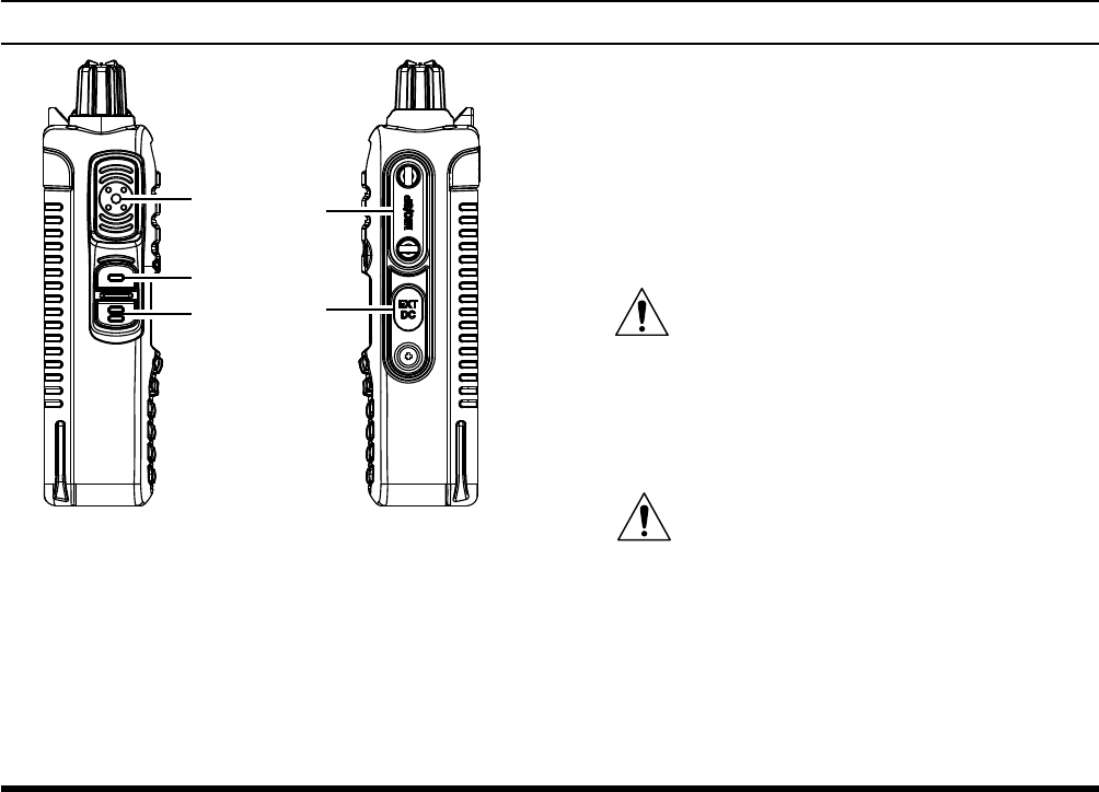
FTA-250L OperATing MAnuAL8
À PTT (Push To Talk) Switch
Press this switch to transmit, and release it to re-
ceive after your transmission is completed.
Á SQL (Squelch) key
This key may be pressed to adjust the squelch
level. Press this key for 1 second to “open” the
squelch continuously. Press this button again to
resume normal (quiet) monitoring.
 LOCK key
Press and hold this key to lock the keypad. To un-
lock, repeat this process.
à MIC/SP Jack
You may connect the supplied SCU-15 Headset
Adapter Cable or the optional SSM-10A Speaker/
Microphone to this jack. To use this jack, you must
rst remove the cover from the transceiver body.
Do not allow the FTA-250L to get wet
while the MIC/SP cover has been re-
moved.
Ä EXT/DC Jack
When an external 9.0 to 10.5-Volt DC power
source is available, you may connect the SDD-12
Cigarette Lighter DC/DC Converter here.
1) Do not allow the FTA-250L to get wet
while the rubber cover is removed.
2) Do not connect any accessory unapproved
by YAESU to supply DC power.
Controls & ConneCtors (left / rIght sIde)
FTA-250L OperATing MAnuAL 9
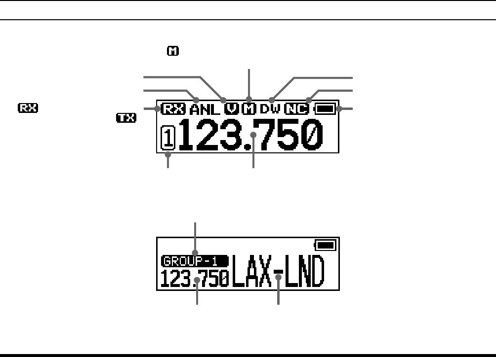
Controls & ConneCtors (lCd)
“” icon appears during
audio reception, or “ ”
during transmission.
ANL Feature Active
Dual Watch Feature ActiveVOX Feature Active
Noise Canceling Feature Active
Battery Indicator
Operating FrequencyStored Frequency Recall Number
Memory Group
Frequency Memory Name
“” icon appears if the selected channel is
programmed into the Scan Memory.
FTA-250L OperATing MAnuAL10
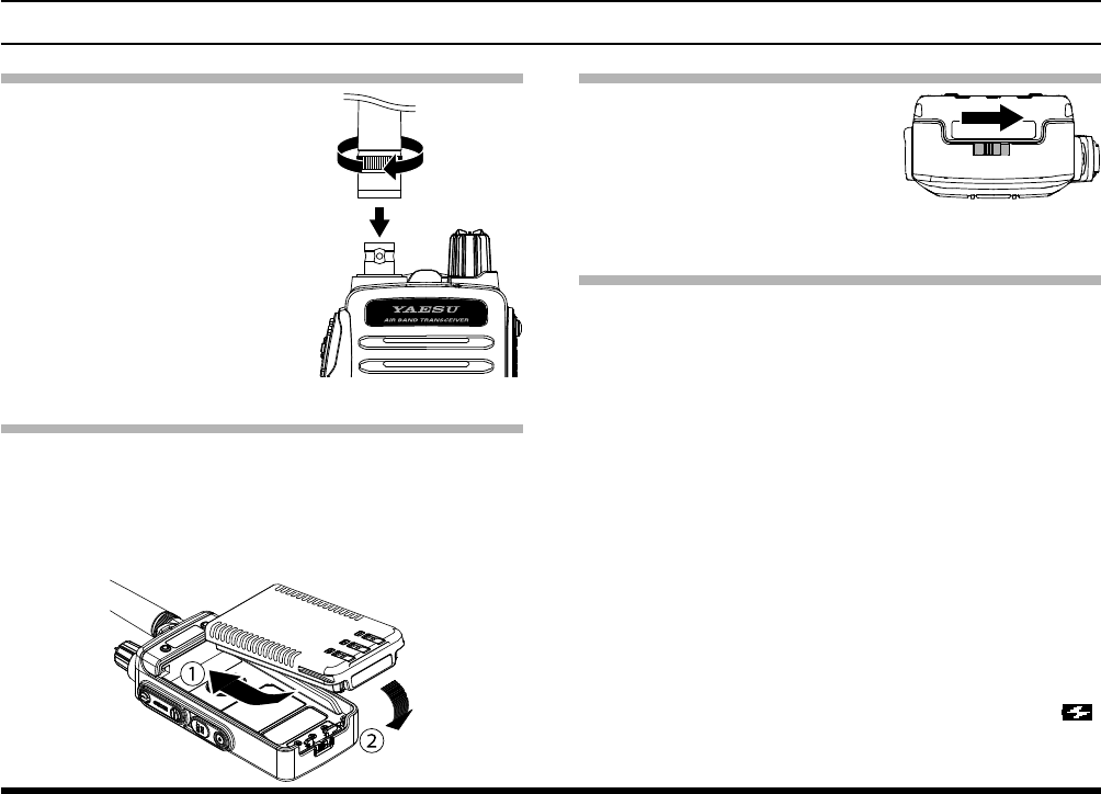
Removing the Battery Pack
1. Turn the transceiver OFF.
2. While sliding the latch in
the direction of the arrow,
as shown in the illustration.
3. Pull out the battery pack
from the transceiver.
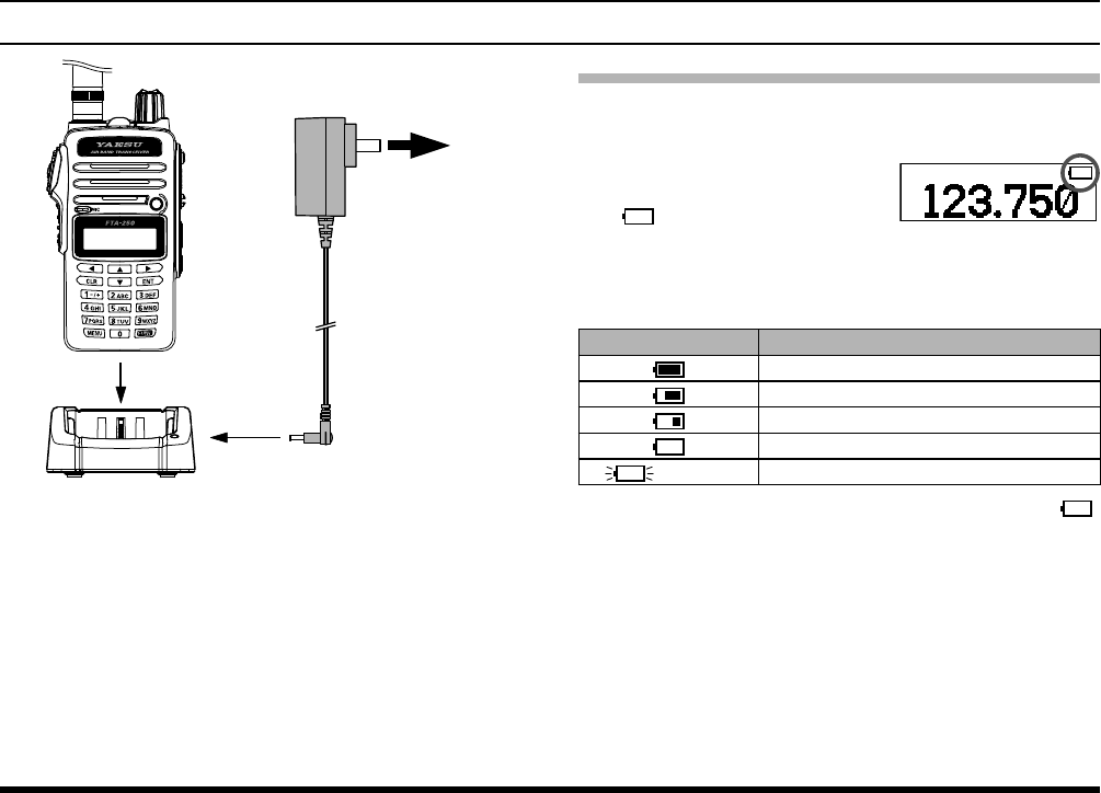
Battery Charging
It is necessary to charge the Lithium-ion battery fully
before its rst use. Follow the procedure below:
1. Install the Lithium-ion battery pack onto the trans-
ceiver. Ensure that the transceiver is switched off.
2. Insert the cable plug of the SAD-20 AC Adapter
into the DC IN jack located on the back of the
SBH-22 Charger Cradle, then plug the SAD-20
into the AC line outlet.
3. Insert the transceiver into the SBH-22 Charger
Cradle.
If the transceiver is inserted correctly, the RED
indicator on the SBH-22 will glow.
You may insert the cable plug of the SDD-
12 Cigarette Lighter DC/DC Converter into
the EXT/DC jack located on the right side
of the transceiver. In this case, the “ ”
icon will appear in the top right corner of the
LCD display for trickle charging.
Before you BegIn
Antenna Installation
To attach the supplied an-
tenna to the FTA-250L, grasp
the base of the antenna
rmly, and exert a moderate
“pinching” pressure on the
base as you press the an-
tenna onto the transceiver’s
antenna connector. While
exerting this pressure, rotate
the antenna clockwise 1/4
turn to lock the antenna in
place.
Installing the Battery Pack
1. Insert the battery pack into the battery compart-
ment on the back of the transceiver (À).
2. Push the battery in until the battery latch on the
lower back side of the transceiver clicks securely
(Á).
FTA-250L OperATing MAnuAL 1111
Before you BegIn
AC line outlet
SAD-20
SBH-22
DC IN jack
A fully-discharged SBR-25LI Battery Pack will
be charged completely in about 3.5 hours (de-
pending on the battery being charged), and
then the GREEN indicator on the SBH-22 will
glow letting you know the battery has been fully
charged.
The SAD-20 is not designed to power the
transceiver for operation (reception or trans-
mission).
4. When charging is complete, disconnect the SAD-
20 from the DC IN jack and the AC line outlet.
Low Battery Indication
As the battery discharges during use, the voltage will
gradually become lower.
When the battery voltage is
too low for reliable operation,
the “ ” icon will blink on the
LCD display, indicating that
the battery pack must be re-
charged before further use.
Icons Description
Full battery power
Enough battery power
Low battery power
Poor battery power
(w/blink) Charge (or replace) the battery
Avoid recharging Li-Ion batteries before the “ ”
indicator is observed, as this can degrade the
charge capacity of your Li-Ion battery pack.
The fully-charged battery lasts for 16 hours on the
FTA-250L under the conditions below:
Battery saver :ON
Operation ratio :TX:RX:Standby=5:5:90 (
duty cycle
)

FTA-250L OperATing MAnuAL1212
Before you BegIn
External DC Power Supply Connection
You may insert the cable plug of the SDD-12 Ciga-
rette Lighter DC/DC Converter into the EXT DC jack
located on the right side of the transceiver.
In this case, the “ ” icon will appear in the top right
corner of the LCD display.
When making DC connections via the SDD-12, be
absolutely certain to observe the proper voltage level
and polarity guidelines.
The SDD-12 can be connected to 12 to 24 Volt DC
power sources.
As close
as possible Ferrite Core
Wind the cable one turn,
then snap two halves.
SDD-12
Cigarette Lighter DC/DC
Converter (12 to 24 Volts).
For noise reduction from exogenous noise, wind
one turn of the SDD-12 cable around the ferrite
core, and snap its two halves together, per the il-
lustration above. Attach the ferrite core as close as
possible to the SDD-12 body, as shown.
Do not connect any accessory unap-
proved by YAESU to supply DC power;
otherwise the FTA-250L may be damaged.
Belt Clip Installation
You may mount the belt clip to the rear of the FTA-
250L using the supplied screws.
FTA-250L OperATing MAnuAL 1313
Before you BegIn
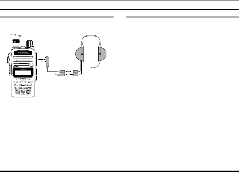
Headset Connection
You may connect an optional headset using the sup-
plied SCU-15 Headset Adapter Cable.
Headset
(not supplied)
SCU-15
Headset Adapter Cable
1. Remove the two screws and cover of the MIC/SP
jack located on the right side of the transceiver.
2. Insert the plug of the SCU-15 to the MIC/SP jack.
3. Fix the plug with two screws attached to the SCU-
15.
Either of the plug directions are acceptable as
long as the both screws t the screw holes.
4. Insert the plugs of the headset to the sockets of
the SCU-15.
Precautions
The FTA-250L is capable of two-way communica-
tion on channels used for critical aviation safety
communications. Therefore, it is important that this
transceiver be kept away from children or other
unauthorized users at all times.
Do not dispose of the Lithium-ion battery pack in a
re. Do not carry a Lithium-ion battery pack in your
pocket, where keys or coins could short the termi-
nals. This could create a serious re/burn danger,
and possibly cause damage to the Lithium-ion
pack.
The FTA-250L is designed to have the waterproof
capability equivalent to IP54. Do not allow the
transceiver to become submerged, and do not
subject it to water spray under pressure.

FTA-250L OperATing MAnuAL14
Turning the power on and off
1. Rotate the PWR/VOL knob
out of the click-stop to turn
the transceiver ON.
2. To turn the transceiver
OFF, turn the PWR/VOL
knob fully counter-clock-
wise into the click-stop po-
sition.
The “ ” icon appears on the display when the
audio signal is received on the current frequency.
Adjusting the volume
1. Rotate the PWR/VOL knob
to adjust the receiver vol-
ume.
Adjusting the squelch
1. Press the SQL key, then
press the [◄] or [►] key
to adjust to a squelch
level (OFF to 15) at which
the background noise is
muted.
2. Press the SQL key to
save the squelch setting
and return to normal op-
eration.
BasIC operatIon
FTA-250L OperATing MAnuAL 1515
BasIC operatIon
Monitor Switch
When listening to a very weak signal from an aircraft
or ground station, you may observe the signal disap-
pearing periodically as the incoming signal strength
becomes too weak to override the squelch threshold
setting.
To disable the squelch temporarily;
1. press and hold the SQL
key for 1 second.
The squelch will remain
open and you should have
a better chance of hearing
weak signals.
2. To return to normal opera-
tion, press the SQL key
momentarily.
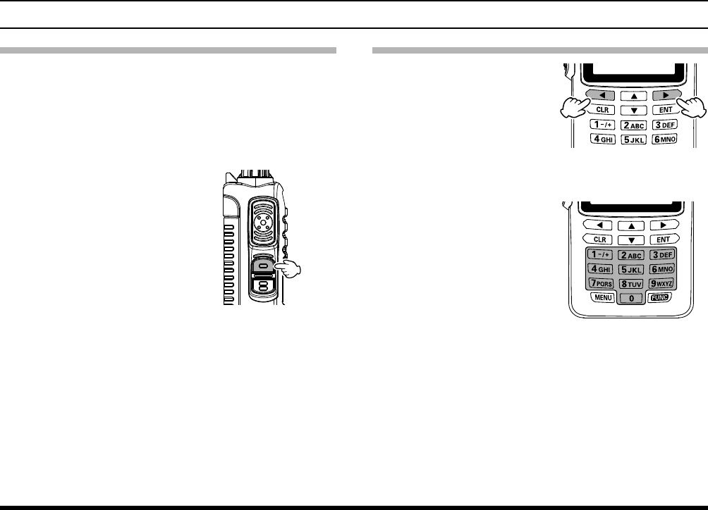
Adjusting the frequency
Pressing the [►] tunes
the FTA-250L toward
a higher frequency,
while pressing the [◄]
will lower the operating
frequency, in steps pre-
programmed for the cur-
rent operating band.
Directly entering fre-
quencies from the
keypad is the easiest
method if you know the
frequency on which you
wish to operate. Just
enter the five digits of
the frequency to move to
that frequency.
For example, to set 134.35 MHz,
press
[1] à [3] à [4] à [3] à [5].
To set 118.275 MHz, you do not need to press the
nal “5” in the frequency as below:
[1] à [1] à [8] à [2] à [7].

FTA-250L OperATing MAnuAL1616
BasIC operatIon
Accessing the 121.5 MHz Emergency Frequency
The FTA-250L can quickly access the 121.500 MHz
emergency frequency. This function can be activated
even when the keypad lock function (described on
page 25) is in use.
1. Press and hold the [121.5]
key.
After four beeps, the
transceiver enters the
emergency mode and the
frequency is automatically
tuned to 121.500 MHz.
2. To exit the emergency
mode, press the [CLR]
key.
The message confirm-
ing the cancelation of the
emergency mode will ap-
pear.
3. Press the [◄] key to se-
lect “YES”, then press the
[ENT] key.
Transmission
1. Press and hold the PTT
switch.
The “ ” icon will ap-
pear on the display during
transmission.
2. Speak into the microphone
area on the front panel of
the radio in a normal voice
level.
3. To return to the receive
mode, release the PTT
switch.
Resetting the Transceiver
To clear all memories and other settings to factory de-
faults:
1. Turn the transceiver OFF.
2. Press and hold the [CLR]
key and [ENT] key while
turning the transceiver
ON.
3. When the LCD backlight
comes on, release the
[CLR] key and [ENT]
key, to reset all settings
to their factory defaults.

FTA-250L OperATing MAnuAL 1717
BasIC operatIon
Operation Modes
The FTA-250L operate in
the modes listed below. You
can switch the modes via
the MENU screen displayed
by pressing the [MENU] key
on the front panel.
When turning on the FTA-250L, the last mode you
have used before turning off will automatically be en-
tered.
COMM
The basic operating mode for communi-
cation.
MEMORY
This mode provides you with the ability to
store and recall as many as 250 channels
in the transceiver’s main memory bank.
WX CH
(WEATHER) (USA/Canada Only)
This mode allows you to receive NOAA
weather channel broadcasts. The 10
weather channels are pre-programmed at
the factory.
SETUP
This mode allows certain aspects of your
radio’s conguration to be customized for
your personal operating conditions.
FTA-250L OperATing MAnuAL1818
BasIC operatIon
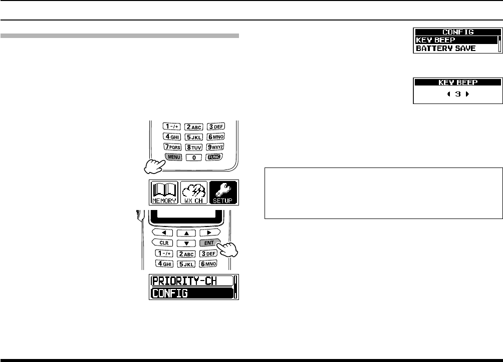
BASIC OPERATION OF THE MENU MODE
Using the menu mode, the various functions of the
FTA-250L can be customized to match the method of
use. You can select the items that you would like to
adjust from the respective lists and enter or select the
appropriate settings for the intended various opera-
tion.
1.
Press the
[MENU] key
.
2. Select
“SETUP” by press-
ing the [◄] or [►] key.
3. Press the [ENT] key.
4. Select the desired menu
item by pressing the [▲]
or [▼] key, and then press
the [ENT] key.
5. Select the desired item by
pressing the [▲] or [▼]
key, and then press the
[ENT] key.
6.
Select
the desired setting
by pressing the [◄] or [►]
key.
7. Press the [ENT] key to store the selected setting.
8. Press the PTT switch to return to normal opera-
tion.
The same operation process as the above is writ-
ten as follows in this operation manual.
[MENU] à “SETUP” à “CONFIG” à “KEY BEEP”

FTA-250L OperATing MAnuAL 19
Pitch Control
The FTA-250L includes a feature that lets you choose
four specific receiver audio responses to allow the
most comfortable and/or effective reception in noisy
environments. The effect is similar to that provided by
an “Equalizer” in a stereo.
1. [MENU] à “SETUP” à “COM SETUP” à “AF
PITCH CONT”
.
2.
Select the receiver audio
response
by pressing the
[◄] or [►] key, and then
press the [ENT] key.
The setting changes in the following order.
NORMAL: The received audio signal does not
pass through the equalizer circuit.
LO CUT: The received audio is passed without
roll-off on the low end.
HI CUT: The received audio is passed without
roll-off on the high end.
HI & LO CUT: The received audio is passed without
roll-off on the high and low ends.
Tip: The default setting: NORMAL
3. Press the PTT switch to return to normal opera-
tion.
Flip-Flop Feature (Frequency Recall)
The FTA-250L can memorize up to 9 operating fre-
quencies automatically, and recall them for later use.
Up to 9 frequencies may be memorized. Once all 9
memories have been programmed, previous frequen-
cies will be over-written, on a rst-in, rst-out basis.
Recall Frequency
1. Press the [▲] key.
You will see the previ-
ously selected recall
number appearing on
the LCD.
2. Press the [▲] or [▼] key to select previously
stored frequencies.
1
à
à 2
à
à 3
à
..... à 7
à
à 8
à
à 9
advanCed operatIon
FTA-250L OperATing MAnuAL2020
advanCed operatIon
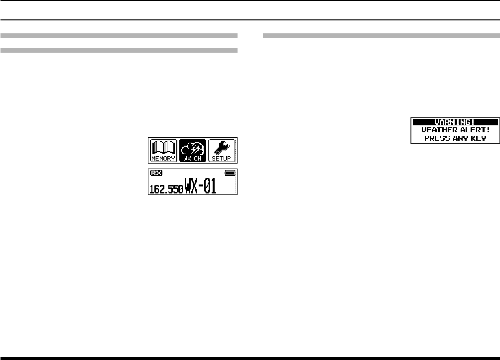
Weather alert reception
In the event of extreme weather disturbances, such
as storms and hurricanes, the NOAA (National Oce-
anic and Atmospheric Administration) sends a weath-
er alert accompanied by a 1050 Hz tone and subse-
quent weather report on one of the NOAA weather
channels.
When the transceiver receives
the weather alert on the op-
erating frequency, it displays
a warning as below on the
screen and continues to make
alarm sounds until either of
the keys is pressed.
You may enable or disable the alarm function when
receiving the weather alert signal via the COMM SET-
UP menu. See page 35 for details.
Reception of Weather Channel Broadcasts
- Weather Channels for USA/ Canada only -
The FTA-250L can receive VHF weather channel
broadcasts, which may assist your flight planning.
The FTA-250L includes a special bank capable of
storing 10 weather channels, which simplies access
when you are in an unfamiliar location.
1.
Press the
[MENU] key
.
2.
Select
“WX CH” by press-
ing the [◄] or [►] key, and
then press the [ENT] key.
The last channel you have
tuned will be received.
3. You can also select a weather channel from the
pre-programmed list with the [▲] or [▼] key.
4. To exit the WX mode, press the [MENU] key, se-
lect the mode other than “WX CH” by pressing the
[◄] or [►] key, and then press the [ENT] key.

FTA-250L OperATing MAnuAL 2121
advanCed operatIon
Dual Watch Operation
The dual watch feature automatically checks for ac-
tivity on the P-ch (priority channel) set via the PRI-
ORITY-CH menu while you are operating on another
channel. During the dual watch operation, the current
channel and the P-ch will be polled alternately for a
200 ms interval.
Setting the P-ch
1. [MENU] à “SETUP” à “PRIORITY CH”
.
2.
Enter the frequency you want to poll, with the key-
pad
.
3.
Select
“FINISH” by press-
ing the [◄] or [►] key, and
then press the [ENT] key.
4. Press the PTT switch to return to normal opera-
tion.
Starting the dual watch
1.
Press the
[FUNC] key
.
2. Select “DUAL WATCH”
by pressing the [◄] or [►]
key, and then press the
[ENT] key.
The display will return to
the previous screen and
the “DW” icon will be dis-
played, indicating the FTA-
250L is in dual watch.
When the transceiver encounters a signal on the
current channel, the radio polls both channels al-
ternately with longer staying time on the current
channel.
When the transceiver encounters a signal in the
P-ch, the transceiver stays on the P-ch until the
signal disappears, and the frequency indication on
the display blinks.
After the signal disappears, the dual watch re-
sumes.
3. To stop the dual watch, repeat steps 1 and 2
above.
FTA-250L OperATing MAnuAL2222
advanCed operatIon
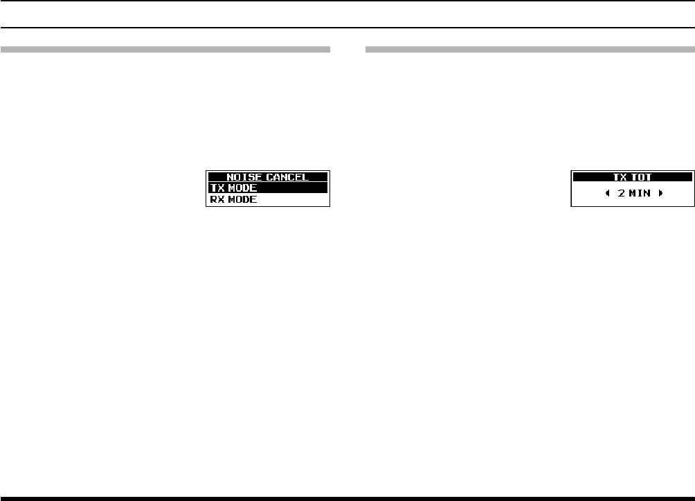
Noise Cancellation
To cancel background noise when transmitting and
receiving.
Enables/disables the Noise-canceling function of the
transmitter and receiver independently.
1. [MENU] à “SETUP” à “COMM SETUP” à
“NOISE CANCEL”
.
2.
Select
“TX MODE” b y
pressing the [◄] or [►]
key, and then press the
[ENT] key.
3. Press the [◄] or [►] key to select “ON” or “OFF”,
and then press the [ENT] key.
4.
Select
“RX MODE” by pressing the [◄] or [►] key,
and then press the [ENT] key.
5. Select the noise level from “LV 1” through “MAX”
or “OFF” by pressing the [◄] or [►] key, and then
press the [ENT] key.
6. Press the PTT switch to return to normal opera-
tion.
TOT Feature
The TOT (time-out timer) shuts off the transceiver af-
ter continuous transmission exceeds the programmed
time. This feature prevents unintended transmission
by mistake and reduces battery consumption.
1. [MENU] à “SETUP” à “COMM SETUP” à
“TX TOT”
.
2.
Select the desired TOT
time
by pressing the [◄]
or [►] key, and then press
the [ENT] key.
The setting changes in the following order.
1
à
à 2
à
à 3
à
à 4
à
à 5 (MIN)
Tip: The default setting: 5 MIN
3. Press the PTT switch to return to normal opera-
tion.
FTA-250L OperATing MAnuAL 2323
advanCed operatIon
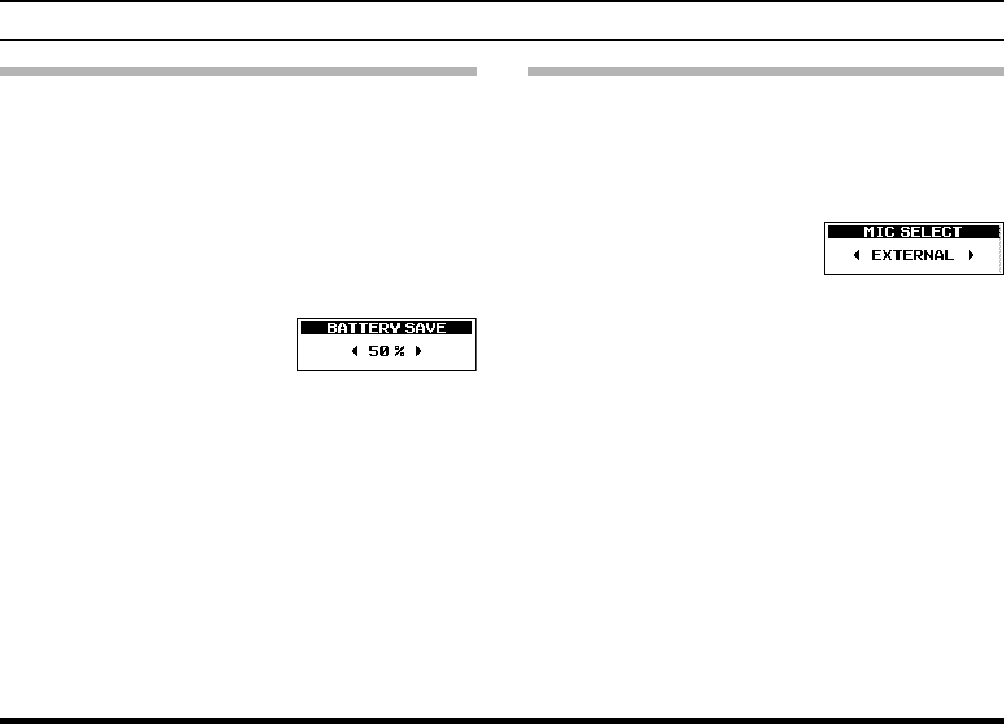
Battery Saver during Reception
One of the important features of the FTA-250L is its
battery saver, which “puts the transceiver to sleep”
for a time interval, periodically “waking it up” to check
for activity. If somebody is talking on the channel,
the FTA-250L will remain in the “awake” mode, then
resume its “sleep” cycles. This feature significantly
reduces battery drain.
1. [MENU] à “SETUP” à “CONFIG” à “BATTERY
SAVE”
.
2.
Select the desired interval
time
by pressing the [◄]
or [►] key, and then press
the [ENT] key.
OFF : Disables this function.
50 % : Sleeps for 100 ms after 100 ms awake
70 % : Sleeps for 250 ms after 100 ms awake
80 % : Sleeps for 450 ms after 100 ms awake
90 % : Sleeps for 900 ms after 100 ms awake
Tip: The default setting: 50 %
3. Press the PTT switch to return to normal opera-
tion.
Using the Headset Microphone
If you want to use the microphone of an aviation
headset, change the assignment of microphone con-
trolled with the PTT switch.
1. [MENU] à “SETUP” à “COMM SETUP” à
“MIC SELECT”
.
2.
Select
“EXTERNAL”
by
pressing the [◄] or [►]
key, and then press the
[ENT] key.
3. Press the PTT switch to return to normal opera-
tion.
When an optional aviation headset is connected, the
PTT switch on the transceiver will activate the head-
set microphone for transmission.
Note: If you nd it difcult to use the PTT switch of
the transceiver, we recommend to use an after-
market external PTT switch.
FTA-250L OperATing MAnuAL2424
advanCed operatIon
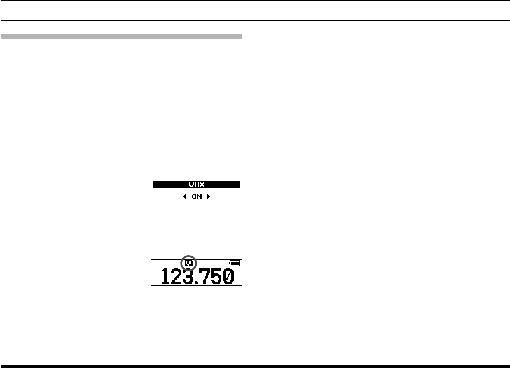
VOX Operation
If you want to have both hands free, use a headset
and activate the VOX (voice-actuated transmit/receive
switching) system.
Notes: The VOX system does not work when us-
ing just the internal microphone; an exter-
nal headset must be used.
Do not activate the VOX system when con-
necting the optional microphone SSM-10A.
1. [MENU] à “SETUP” à “COMM SETUP” à
“VOX”
.
2.
Select
“ON” or “OFF” by
pressing the [◄] or [►]
key, and then press the
[ENT] key.
3. Press the PTT switch to
return to normal operation.
The “V” icon, which indi-
cates that the VOX system
is active.
To adjust the VOX gain, select one of the follow-
ing gain levels on the item “VOX LEVEL” of the
COMM SETUP menu in the SETUP mode.
MIN / LV1 / LV2 / LV3 / MAX
To set the VOX delay, select one of the following
times on the item “VOX DELAY” of the COMM
SETUP menu in the SETUP mode.
0.5 / 1.0 / 1.5 / 2.0 / 3.0 (SEC)
FTA-250L OperATing MAnuAL 2525
advanCed operatIon
Side Tone Control
When utilizing an external headset, you may moni-
tor your own voice when talking into the microphone
through the headphones.
Note: Do not activate the side tone function when
connecting the optional microphone SSM-10A.
1. [MENU] à “SETUP” à “COMM SETUP” à
“SIDE TONE”
.
2.
Select
the side tone level
by pressing the [◄] or [►]
key, and then press the
[ENT] key.
The setting changes in the following order.
OFF / LV 1 / LV 2 / LV 3 / MAX
3. Press the PTT switch to return to normal opera-
tion.
To change the side tone level temporarily during
the monitoring, pressing the [▲], [▼], [◄] or [►]
key when pressing and holding the PTT switch.
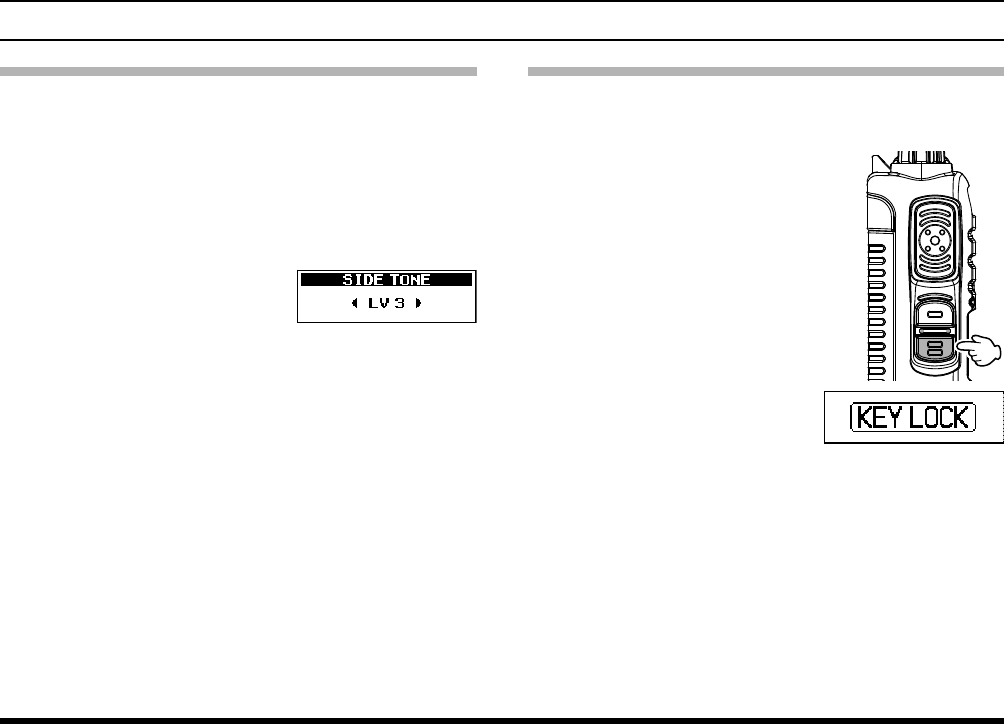
Lock Function
This function prevents accidental changes to the fre-
quency setting and the keypad controls.
1. Press and hold the LOCK
key.
While the FTA-250L
is locked, the controls
with the keys except
the PTT switch, SQL
key, LOCK key, the
PWR/VOL knob, and
the [121.5] key are dis-
abled.
If any of the keys is
pressed, either of “KEY
LOCK” will appear
on the screen for 2
seconds and then the
display will return to the
previous screen.
2. To turn the lock feature off, press and hold the
LOCK key again.
“UNLOCK” will appear on the screen for 2 sec-
onds and then the display will return to the previ-
ous screen.
FTA-250L OperATing MAnuAL2626
advanCed operatIon
PTT Lock Function
This function prevents accidental transmissions by
locking or disabling the PTT switch.
Turning lock/unlock the PTT lock function
You may enable or disable the PTT lock function.
1. [MENU] à “SETUP” à “CONFIG” à “PTT LOCK”
.
2. Select “ON” or “OFF” by
pressing the [▲] or [▼]
key, and then press the
[ENT] key.
3. Press the PTT switch to return to normal opera-
tion.
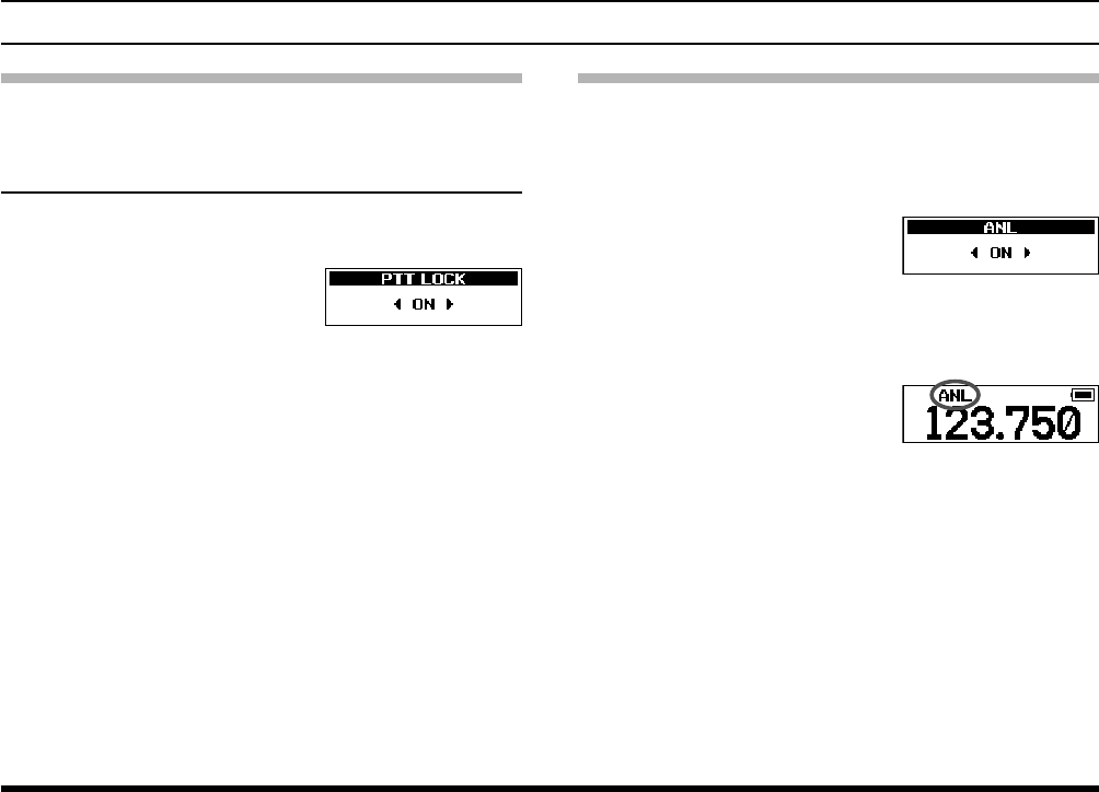
ANL Feature
For reduction of impulse noise, such as that produced
by an engine’s ignition system, the ANL (automatic
noise limiter) feature may prove helpful.
1. [MENU] à “SETUP” à “COMM SETUP” à “ANL”
.
2. Select “ON” or “OFF” by
pressing the [▲] or [▼]
key, and then press the
[ENT] key.
3. Press the PTT switch to
return to normal operation.
The “ANL” icon, which
indicates that the ANL sys-
tem is active.

FTA-250L OperATing MAnuAL 2727
advanCed operatIon
Changing the Channel Steps
The synthesizer of the FTA-250L provides the option
of utilizing 8.33*/25 kHz channel steps.
* 8.33 kHz; Europe only
1. [MENU] à “SETUP” à “COMM SETUP” à “FREQ
STEP”
.
2. Select “25KHZ” o r
“8.33KHZ” by pressing the
[▲] or [▼] key, and then
press the [ENT] key.
3. Press the PTT switch to return to normal opera-
tion.
Note: When you set the channel step to 8.33 kHz,
the channel display differs from actual operat-
ing frequency; see the chart below. However,
the operator (pilot, tower, control, etc.) will call
out the frequency according to what the display
indicates.
Operating
Frequency
Display
8.33 kHz Step 25 kHz Step
1**.0000 MHz 1**.005 1**.000
1**.0083 MHz 1**.010
1**.0166 MHz 1**.015
1**.0250 MHz 1**.030 1**.025
1**.0333 MHz 1**.035
1**.0416 MHz 1**.040
1**.0500 MHz 1**.055 1**.050
1**.0583 MHz 1**.060
1**.0666 MHz 1**.065
1**.0750 MHz 1**.080 1**.075
1**.0833 MHz 1**.085
1**.0916 MHz 1**.090
The adjacent channel selectivity will be slightly
degraded while receiving using 8.33 kHz channel
steps.