Yaesu Musen HX460S Marine Transceiver User Manual F HX460S HX460S NEW
Yaesu Musen Co., Ltd. Marine Transceiver F HX460S HX460S NEW
Contents
- 1. users manual
- 2. revised users manual
revised users manual
HX460S
HX460S
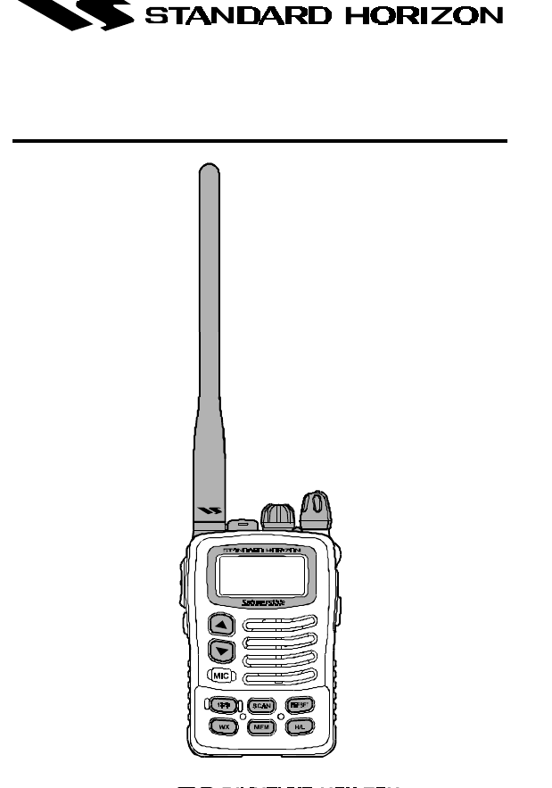
VHF/FM Marine
Handheld Transceiver
Owner's Manual

HX460S
TABLE OF CONTENTS
FCC NOTICE ................................ 1
GENERAL INFORMATION.......... 2
INTRODUCTION .......................................... 2
FCC/INDUSTRY CANADA INFORMATION ..... 2
ACCESSORIES............................ 3
PACKING LIST ............................................. 3
OPTIONS ..................................................... 3
CONTROLS AND INDICATORS .4
CONTROLS and CONNECTIONS .................. 4
INDICATORS ............................................... 7
OPERATION ................................. 9
INITIAL SETUP ............................................ 9
RECEPTION .............................................. 10
TRANSMISSION .........................................11
TRANSMIT TIME-OUT TIMER (TOT) .............11
USA, CANADIAN, AND
INTERNATIONAL BANDS ........................... 12
NOAA WEATHER CHANNELS .................... 12
SCAN ........................................................ 12
PRIORITY SCAN ........................................ 13
NOAA WEATHER ALERT ........................... 14
EMERGENCY CHANNEL 16 ....................... 14
CHANNEL 9 ............................................... 14
OPERATING ON CHANNEL 13 ................... 15
OPERATING ON CHANNEL 67 ................... 15
PRESET CHANNELS (A ~ E):
INSTANT ACCESS ..................................... 15
Programming ........................................... 15
Operation ................................................ 16
SIMPLEX/DUPLEX CHANNEL USE ............. 16
BAROMETRIC PRESSURE METER ............ 17
SETUP MODE ............................................ 18
CLONING .................................................. 20
RESETTING THE TRANSCEIVER’S
MICROPROCESSOR .................................. 21
BATTERY .................................... 23
BATTERY CHARGING ................................ 23
BATTERY REMOVAL/INSTALLATION........... 23
USING THE NC-72 BATTERY CHARGER .... 24
FBA-23 ALKALINE BATTERY CASE ............ 24
BATTERY SAFETY ..................................... 25
MAINTENANCE ......................... 26
SPECIFICATIONS ...................... 27
RF Exposure Safety Statement
SAFETY INFORMATION
Your wireless handheld portable transceiver contains a low power transmit-
ter. When the Push-to-Talk (PTT) button is pushed, the transceiver sends
out radio frequency (RF) signals. In August 1996, the Federal Communica-
tions Commission adopted RF exposure guidelines with safety levels for
hand-held wireless devices.
This device is authorized to operate at a duty factor not to exceed 50% (this
corresponds to 50% transmission time and 50% reception time).
WARNING: To maintain compliance with the FCC’s RF exposure guidelines,
this transmitter and its antenna must maintain a separation distance of at
least 1 inch (2.5 centimeters) from your face. Speak in a normal voice, with
the antenna pointed up and away from the face at the required separation
distance.
If you use a headset accessory for this radio, with the radio worn on your
body, use only the Vertex Standard belt clip for this transceiver, and ensure
that the antenna is at least 1 inches (2.5 centimeters) from your body when
transmitting.
Use only the supplied antenna. Unauthorized antennas, modifications, or at-
tachments could damage the transmitter, and may violate FCC regulations.

HX460S
Congratulations on your purchase of the HX460S! Whether this is your first
portable marine VHF transceiver, or if you have other STANDARD HORI-
ZON equipment, The STANDARD HORIZON organization is committed to
ensuring your enjoyment of this high-performance transceiver, which should
provide you with many years of satisfying communications even in the harsh-
est of environments. STANDARD HORIZON technical support personnel
stand behind every product we sell, and we invite you to contact us, should
you require technical advice or assistance, at (562) 404-2700.
We appreciate your purchase of the HX460S, and encourage you to read
this manual thoroughly, so as to learn and understand the capabilities of the
HX460S fully.
FCC NOTICE
NOTICE
Unauthorized changes or modifications to this equipment may void com-
pliance with FCC Rules. Any change or modification must be approved
in writing by STANDARD HORIZON, a Marine Division of VERTEX STAN-
DARD.
NOTICE
This equipment has been tested and found to comply with the limits for
a Class B digital device, pursuant to Part 15 of the FCC Rules. These
limits are designed to provide reasonable protection against harmful
interference in a residential installation. This equipment generates, uses
and can radiate radio frequency energy and, if not installed and used in
accordance with the instructions, may cause harmful interference to
radio communications. However, there is no guarantee that interference
will not occur in a particular installation. If this equipment does cause
harmful interference to radio or television reception, which can be de-
termined by turning the equipment off and on, the user is encouraged to
try to correct the interference by one or more of the following measures:
•Increase the separation between the equipment and receiver.
•Connect the equipment into an outlet on a circuit different from that to
which the receiver is connected.
•Consult the dealer or an experienced marine electronics technician
for help.
Page 1

HX460S
1. GENERAL INFORMATION
1.1 INTRODUCTION
The HX460S is a submersible, miniature 5-Watt portable two-way VHF ma-
rine transceiver. The transceiver has 173 channels: 163 marine and 10
weather. The 163 marine channels are switchable to comply with USA, In-
ternational, or Canadian regulations. It has an emergency channel 16 which
can be immediately selected from any channel by pressing the 16/9 key.
NOAA weather channels can also be accessed immediately by pressing the
WX key.
The transceiver includes the following features: Memory Scanning, Priority
Scanning, NOAA Weather Alert, Battery Saver, easy-to-read large LCD dis-
play, EEPROM memory back-up, Battery Life displayed on LCD, and a trans-
mit Time-Out Timer (TOT).
The transmitter provides a maximum of 5 Watts output, and has the selection
of 2.5 Watts and 1 Watt to assist the user in ensuring maximum battery life.
The optional SU-1 Barometric Pressure Sensor Unit can be installed to pro-
vide readout of the current barometric pressure.
1.2 FCC/INDUSTRY CANADA INFORMATON
The following data pertaining to the transceiver is necessary to fill out the
license application.
FCC Type Accepted ............................................................................ Part 80
Output Power with CNB460 ..........1 W (Low), 2.5 W (Mid), and 5 W (High)
Emission............................................................................................16K0F3E
Frequency Range ................................................... 156.025 to 163.275 MHz
FCC Type Number.......................................................................K66HX460S
Industry Canada Type Approval ....................................... Approval Pending
Additional FCC and Industry Canada data, including licensing re-
quirements, are contained in the companion document titled
OWNER’S MANUAL SUPPLEMENT. The document also contains
charts for VHF channel assignments, transceiver operating proce-
dures, maintenance, factory service information, and warranty data.
Page 2

HX460S
Page 3
2. ACCESSORIES
2.1 PACKING LIST
When the package containing the transceiver is first opened, please check
it for the following contents:
• HX460S Transceiver
• CNB460 1100 mAh Lithium Ion Battery Pack
• NC-72B 120VAC Wall Charger for CNB460
• CAT460 Antenna
• E-DC-19 DC Cable with 12 V Cigarette Lighter Plug for the CNB460
• Quick Draw Belt Clip
• Carrying Strap
• Owner’s Manual (P/N EC010N100)
• Owner’s Manual Supplement (P/N E00005004)
2.2 OPTIONS
NC-72C 230-240 VAC Wall Charger for the CNB460
FBA-23 Alkaline Battery Case
SU-1 Barometric Pressure Sensor Unit
CMP460 Noise-canceling Waterproof Speaker/Microphone
VC-24 VOX Headset
E-DC-6 DC Cable; plug and wire only
MCC460 Soft Case
CAW230 Radio-to-Ship’s-Antenna Adapter
Note: Before operating the HX460S for the first time, it is recommended that
the battery be charged. Please see section 5.3 OPERATING BATTERY
CHARGER for details.
HX460S
Page 4
3. CONTROLS AND INDICATORS
NOTE
This section defines each control of the transceiver. For detailed oper-
ating instructions, refer to section 4 of this manual. Refer to Figure 1 for
the location of the following controls, indicators, and connections.
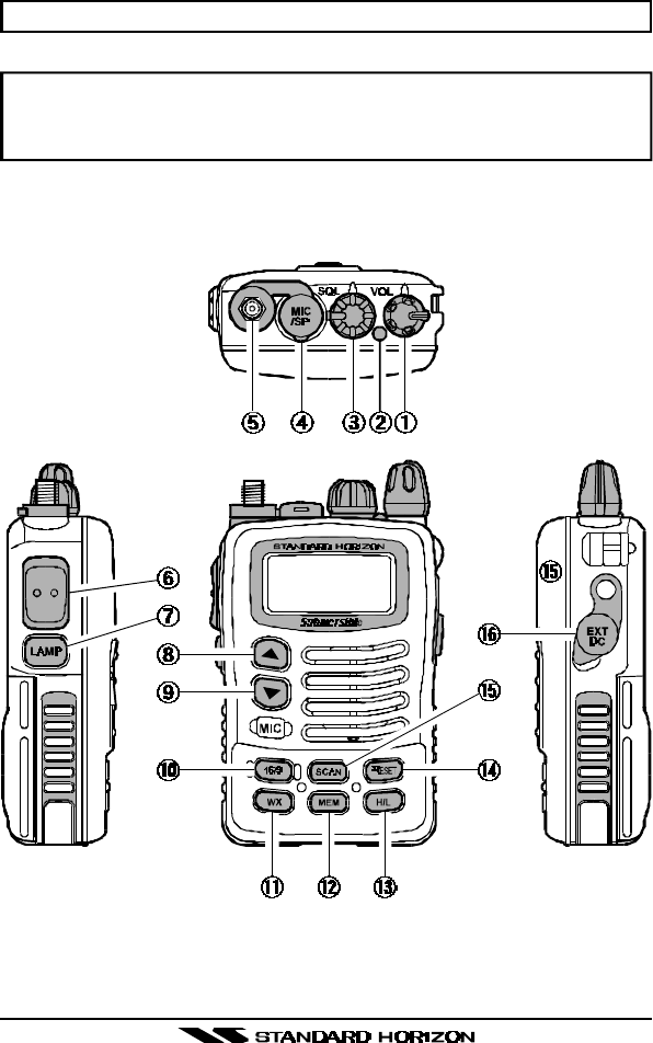
3.1 CONTROLS AND CONNECTIONS
Figure 1
Controls and Connectors
HX460S
Page 5
POWER SWITCH/VOLUME CONTROL
Turns the transceiver on and off, and adjusts the volume.
BUSY/TX INDICATOR
This indicator glows green when a signal is being received and red when
transmitting. It also glows red during charging of the of the CNB460
Lithium Ion battery pack and green when charging is completed.
SQUELCH (SQL) CONTROL
Sets the point at which random noise on the channel does not activate
the audio circuits but a received signal does. This point is called the
Squelch threshold. Further adjustment of the squelch control will de-
grade the reception of wanted transmissions.
MIC/SP JACK
Accepts the optional CMP460 Speaker/Microphone or VC-24 VOX Head-
set. When this jack is used, the internal speaker is disabled.
Antenna Connector
Connect the supplied CAT460 flexible antenna here.
PUSH-TO-TALK (PTT) SWITCH
Activates transmission.
LAMP KEY
Turns the lamp (for LCD and Keypad back-lighting) on and off.
Hold down this key to lock the displayed channel functions (except the
H/L, PTT, and LAMP keys) so that they are not accidentally changed.
The key lock symbol “ ” will appear, to indicate that the functions are
locked. Hold down until the key lock symbol “ ” disappears to unlock
the radio.
UP (p) KEY
Selects the desired channel. Each press increases the channel number.
When held down, the channels increase continuously.
DOWN (q) KEY
Selects the desired channel. Each press decreases the channel num-
ber. When held down, the channels decrease continuously.

HX460S
Page 6
16/9 KEY
Immediately recalls channel 16 from any channel location. Holding down
this key recalls channel 9.
WX KEY
Immediately recalls the last-used NOAA Weather Channel from any chan-
nel location. Recalls the previously- selected working channel when the
WX key is pressed again.
Secondary use: When the 16/9 key is held and the WX key is pressed,
the radio will change modes between the USA, International, and Cana-
dian channel sets.
MEM KEY
Memorizes the selected channel for scanning. Holding this key will de-
lete a memorized channel. (“MEM” appears on the LCD display during
memory operation).
H/L KEY
Toggles the transmitter power level between High (5 Watts), Medium
(2.5 Watts), and Low (1 Watt) of output. Does not operate on “low power
only” and transmission-inhibit channels.
When operating on Canadian channel 13, or USA channels 13 or 67,
pressing this key momentarily toggles the power level from Low power
to Medium or High power.
PRESET KEY
Immediately recalls one of up to five user preset memories for operation
(shown as
A
-
E
on the LCD). Pressing this key repeatedly scrolls through
the preset memory channels.
SCAN KEY
Starts scanning and Priority scanning of programmed channels. When
scanning, press and hold this key to turn on and off Priority scan (PRI is
shown on the left side of the display during Priority scanning).
EXT DC JACK
This DC input jack allows connection to an external DC power source (6-
16V DC). When the radio is turned off, and external power (above 9.7 V)
is applied, the battery will be charged.
HX460S
Page 7
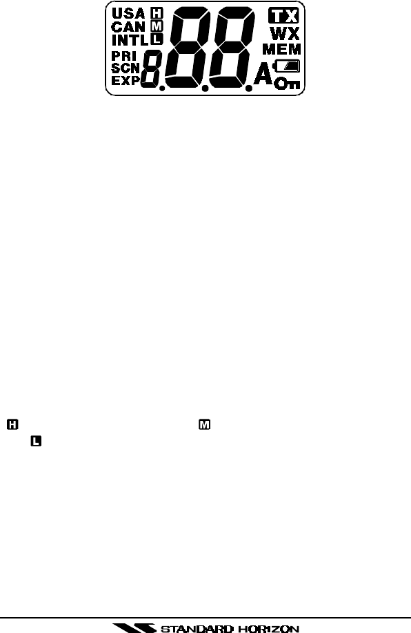
3.2 INDICATORS
Figure 2
Indicators
Channel Display
The operating channel is shown on the LCD in both the transmission and
reception modes. When the optional SU-1 Barometric Pressure Sensor Unit
is installed, the LCD may be configured to indicate the current Barometric
Pressure.
A Indicator
Signifies ship-to-ship channels in USA or Canadian mode (whose counter-
part in the International mode is a public correspondence (marine operator)
channel).
USA/CAN/INTL Indicator
Denotes the “band” of operation for the particular channel. “USA” indicates
the USA band; “CAN” indicates the Canadian band; and “INTL” indicates
the International band. Refer to the Owner’s Manual Supplement for a list of
channels.
H/M/L Indicators
“” indicates High power (5 Watts); “ ” indicates Medium power (2.5 Watts);
and “ ” is for Low power (1 Watt). “Blank” in this location indicates a recep-
tion-only channel.
PRI Indicator
Priority Scan is activated.
SCN Indicator
Scan is activated.
TX Indicator
Appears during transmission.

HX460S
Page 8
WX Indicator
NOAA weather channel.
MEM Indicator
The channel is in the transceiver’s “Scan Memory.”
Battery Indicator
When transmitting, this indicator appears when the battery capacity is ap-
proximately 60%. When the battery capacity is approximately 10%, this
indicator will blink.
NOTE: The battery indicator should be used only as a guide in charging the
CNB460 battery.
KEY Lock Indicator
When the symbol is shown on the LCD, all keys are disabled except for the
H/L, PTT and LAMP keys.
HX460S
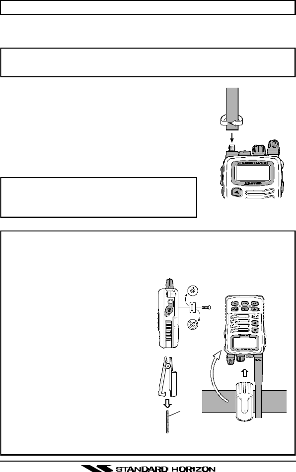
How to use the Quick Draw Belt Clip
1. Connect the hanger to the rear of the HX460S, with the notch point-
ing directly up, using the supplied screw (Figure 4-a).
Use only the screw included
with the clip to mount the clip
to the back of the transceiver!
2. Clip the Quick Draw Belt Clip to
your belt (Figure 4-b).
3. To install the HX460S into the
Quick Draw Belt Clip, align the
hanger with the Quick Draw Belt
Clip and slide the HX460S into
its slot until a click is heard.
4. To remove the HX460S from the
Quick Draw Belt Clip, Rotate the
HX460S 180 degrees, then slide
the transceiver out from the Quick
Draw Belt Clip (Figure 4-c).
Page 9
4. OPERATION
4.1 INITIAL SETUP
NOTE
Never key the transceiver without an antenna connected, as this may
cause damage to the transceiver.
1. Install the belt clip on the transceiver, if desired.
2. Install the nylon carrying strap on the the trans-
ceiver, if desired.
3. Install the battery pack on the transceiver (see
figure 6 and section 5.2).
4. Install the antenna onto the transceiver.
NOTE
Water resistance of the transceiver is assured
only when the battery pack and antenna are
attached to the transceiver. Figure 3
Antenna Installation
Figure 4
(a)
(b) (c)
belt

HX460S
Page 10
4.2 RECEPTION
1. Turn the POWER/VOLUME CONTROL knob clockwise to turn the trans-
ceiver on.
2. Turn the SQUELCH CONTROL knob fully counterclockwise. This state
is known as “Squelch Off.”
3. Turn up the POWER/VOLUME CONTROL knob until the noise or audio
from the speaker is at a comfortable level.
4. Select a channel that has no signal being received (no one is transmit-
ting on the channel) and where only noise is heard.
5. Slowly turn the SQUELCH CONTROL knob clockwise and stop immedi-
ately after the noise disappears. This condition is known as the “Squelch
Threshold.” If the knob is turned clockwise past this point, weak signals
may not be received. No noise or no signal is heard until a signal is
received that exceeds the squelch threshold.
6. To change channels, press the [p] or [q] key. Sometimes, a slight ad-
justment of the squelch threshold is needed, as some channels have a
higher noise level than others.
7. Please refer to the Owner’s Manual Supplement for a complete listing of
all USA, International and Canadian VHF Marine channels and their uses.
8. If necessary, press the LAMP key to turn on the display illumination. The
lamp automatically turns off in about 5 seconds. To turn off the lamp,
press the LAMP key again.
9. To “lock” the channel so that it is not accidentally changed, hold down
the LAMP key for about one second. This locks the [p] and [q] buttons
and all the front panel controls except the H/L, PTT and LAMP keys. The
“” symbol will appear on the display to indicate that the keypad is
locked. Hold down the LAMP key for about one second to unlock the
keys. The “ ” symbol will disappear from the display..

HX460S
Page 11
4.3 TRANSMISSION
1. Perform steps 1 through 7 of the RECEPTION discussion above.
2. Before transmitting, monitor the channel and make sure it is clear.
THIS IS AN FCC REQUIREMENT!
3. For communications over short distances, press the H/L key until “ ” is
displayed on the LCD. This indicates Low power (approximately 1 Watt).
NOTE
Transmitting on 1 Watt prolongs battery life. Low power (1 Watt)
should be selected whenever possible.
4. If using Low power is not effective, select Medium power (2.5 Watts) or
High power (5 Watts) by pressing the H/L key until “ ” (Medium power)
or “ ” (High power) is displayed.
5. When receiving a signal, wait until the incoming signal stops before trans-
mitting. The transceiver cannot transmit and receive simultaneously.
6. Press the PTT (Push-To-Talk) switch to transmit. The “TX” indicator is
displayed during transmission.
7. Speak slowly and clearly into the microphone. Hold the microphone about
½ to 1 inch away from your mouth.
8. When the transmission is finished, release the PTT switch.
9. Refer to the OWNER’S MANUAL SUPPLEMENT for an overview of com-
mon transceiver operating procedures.
4.4 TRANSMIT TIME - OUT TIMER (TOT)
While the PTT switch is held down, transmission time is limited to 5 minutes.
This prevents prolonged (unintentional) transmissions. About 10 seconds
before automatic transmitter shutdown, a warning beep sounds from the
speaker. The transceiver automatically switches to the receiving mode, even
if the PTT switch is held down. Before transmitting again, the PTT switch
must first be released, then pressed again. This Time-Out Timer (TOT) pre-
vents a continuous transmission that would result from an accidentally stuck
PTT switch.

HX460S
Page 12
4.5 USA, CANADIAN, AND INTERNATIONAL BANDS
1. To change the operating band (channel set) of the transceiver, hold down
the 16/9 key and press the WX key. The band will change from USA, to
International, and to Canadian with each press.
2. “USA” appears on the LCD for the USA band, “CAN” appears for the
Canadian band, and “INTL” appears for the International band.
3. Refer to the marine channel charts in the OWNER’S MANUAL SUPPLE-
MENT for allocated channels in each band.
4.6 NOAA WEATHER CHANNELS
1. To receive a NOAA weather channel, press the WX key. The transceiver
changes to the weather channel mode. This mode consists of a special
pre-set memory bank containing the standard NOAA weather channels.
2. The transceiver will be set to the last-used NOAA weather channel. Press
the [p] or [q] key to change to other weather channels.
3. To exit from the weather channel mode, press the WX key. The trans-
ceiver will revert to the channel you were using prior to switching to the
weather channel mode.
4.7 SCAN
This transceiver provides a special “Scanning Memory Bank” which allows
you to designate certain channels for inclusion in a “loop” which will be
scanned at high speed. If an incoming signal is detected on one of the chan-
nels in the scanning loop, the radio will pause on that channel, allowing you
to listen to the incoming transmission.
1. Select the desired channel to be included in the scanning loop using the
[p] or [q] key.
2. Press the MEM key to store the channel into the transceiver’s scanning
memory. “MEM” will be displayed on the LCD.
3. Repeat steps 1 and 2 for all the channels to be scanned.
4. To delete a channel from the transceiver’s scan memory, press the MEM
key again while the memorized channel is displayed. “MEM” will disap-
pear from the display.
5. All channels programmed remain in the transceiver’s scan memory even
if the power is turned off. See section 4.17: “RESETTING THE
TRANSCEIVER’S MICROPROCESSOR” to clear all channels from the
transceiver’s scan memory.

HX460S
Page 13
6. Adjust the SQUELCH CONTROL knob until background noise is elimi-
nated.
7. To start scanning, press the SCAN key. The scan proceeds from the
lowest to the highest programmed channel number and stops on chan-
nels when a transmission is received. Scanning will resume when the
squelch closes after the incoming signal disappears at the end of the
transmission.
8. To stop the scan, press the SCAN, 16/9, WX, or PRESET key.
4.8 PRIORITY SCAN
The priority scanning feature allows the radio to scan while also keeping
watch on a particularly important “priority channel.” The following channels
can be set as the priority channel: 16, 09, and Preset Channels A through E
(Preset Channels are described in section 4.14).
1. To set the priority channel, hold down the 16/9 key and press the MEM
key. The channel will change from 16 to 09 to Preset A to Preset B to
Preset C to Preset D to Preset E with each press of the MEM key. The
displayed channel will be set as the priority channel when the 16/9 key is
released.
2. For priority scanning, hold down the SCAN key during normal scanning.
Scanning will proceed between the memorized channels and the priority
channel. The priority channel will be scanned after each programmed
channel. “PRI” is shown on the left side of the channel number during
priority scanning.
3. As an example of priority scanning, let us say that channels 06, 07, and
08 are memorized in the transceiver’s scan memory. Priority scanning
will proceed in the following sequence:
[CH06] à [Priority Channel] à [CH07] à [Priority Channel] à
[CH08] à [Priority Channel] à [CH06] à [Priority Channel] ……
4. Even when the transceiver stops and listens to the signal of a programmed
channel, the transceiver will shift to a “dual watch” mode between this
channel and the priority channel. Therefore, your priority watching of the
designated channel is not compromised when the scanner has paused
on an active channel.

HX460S
Page 14
4.9 NOAA WEATHER ALERT
In the event of extreme weather disturbances such as storms and hurri-
canes, NOAA (National Oceanic and Atmospheric Administration) sends a
“weather alert” consisting of a 1050 Hz tone, followed by weather reports on
the weather channels. The transceiver is capable of receiving this alert if the
following is performed:
1. Program your area’s weather channels into the transceiver’s scan
memory. Follow the same procedure as for regular channels under Sec-
tion 4.7.
2. Press the SCAN key to start the scan.
3. The memorized weather channels are scanned along with the regular
memorized channels. Scanning will not stop, however, on the (continu-
ous) weather broadcast channels unless the weather alert tone is re-
ceived.
4. When an alert is received on a weather channel, scanning stops and the
transceiver emits a beeping tone that will stay on for 5 minutes or until
the user presses the WX key to listen to the Weather Alert.
NOTICE
Take care not to damage your hearing when operating with the optional
VC-24 VOX Headset or Earpice. The NOAA Weather Alert Tone will be
emitted at full volume, irrespective of the setting of the POWER/VOL-
UME CONTROL konb.
4.10 EMERGENCY CHANNEL 16
1. To select the emergency channel, press the 16/9 key from any channel.
2. If you cannot contact anyone on channel 16, switch to another channel.
3. See the OWNER’S MANUAL SUPPLEMENT for additional emergency
operating practices.
4. To recall the previously-used channel when you are finished on channel
16, press the 16/9 key again.
4.11 CHANNEL 9
Channel 9 is used as a hailing channel for initial, non-emergency contacts
with other vessels. Hold down the 16/9 key for 1 second to select channel 9.
You should shift to a different channel, by mutual agreement with the other
vessel’s operator, after contact is established (so as to keep the hailing chan-
nel clear for other users).

HX460S
Page 15
4.12 OPERATING ON CHANNEL 13
Channel 13 is used at docks, bridges and for maneuvering in port. Mes-
sages on this channel must concern navigation only, such as meeting and
passing in restricted waters. In emergencies and when approaching blind
river bends, High power is allowed. Pressing the H/L key will change the
power output from 1 Watt ( ) to 5 Watts ( ); if pressed again, 2.5 Watts
( ) will be selected. When the PTT switch is released, the transceiver will
revert to Low power. Press the H/L key again if you need High power on a
subsequent transmission.
4.13 OPERATING ON CHANNEL 67
When channel 67 is used for navigational bridge-to-bridge traffic between
ships, High or Medium power may be used temporarily (in the USA band) by
pressing the H/L key. When the PTT switch released, the transceiver will
revert to low power.
4.14 PRESET CHANNELS (A ~ E): INSTANT ACCESS
Five user-assigned channels can be programmed for instant access. Press-
ing the PRESET key provides activates the user-assigned channel bank. If
the PRESET key is pressed and no channels have been assigned, an alert
beep will be emitted twice from the speaker (if the beeper has been en-
abled; see Section 4.17.1 KEY BEEP on page 18).
4.14.1 Programming
Hold down the PRESET key, and press the [p] or [q] key (repeatedly, if
necessary) until the desired channel number (from among the regular oper-
ating channels) is displayed.
With the desired channel number displayed, release the PRESET key. The
“A” notation will appear on the LCD display, indicating that the displayed
channel is now saved in the Preset Channel A position.
Repeat steps 1 and 2 to program the desired channels into Preset Channels
b ~ E.
To delete a Preset Channel, hold down the PRESET key and press the [p]
or [q] key until the Preset Channel number to be deleted is displayed, then
release the PRESET key.

HX460S
Page 16
4.14.2 Operation
Pressing the PRESET key toggles between Preset Channel A, b, C, d, E,
and the last selected “regular” channel. Preset Channel A is represented by
“A” to the left of the channel number on the LCD, and channel B is repre-
sented by “b,” and so forth. The letter “A” should not be confused with the
“A” that sometimes is displayed to the right of the channel number (described
in the section 3.2 of this Owner’s Manual).
4.15 SIMPLEX/DUPLEX CHANNEL USE
All channels are factory-programmed in accordance with FCC (USA), In-
dustry Canada and International regulations. The mode of operation cannot
be altered from simplex to duplex or vice-versa. Simplex or duplex mode is
automatically activated, depending on the channel and whether the USA,
International or Canadian operating band is selected. Refer to the channel
charts in the OWNER’S MANUAL SUPPLEMENT.
HX460S
Page 17
4.16 BAROMETRIC PRESSURE METER
The optional Barometric Pressure unit (SU-1) brings to the HX460S the unique
capability of providing readout of the current barometric pressure. The SU-1
unit requires calibration of the ‘offset’ parameters, so that the pressure reading
will be correct. To do this you must have a barometer to use as a reference as
you adjust the SU-1 to match its reading; see section 4.17.6 boF (Barometric
Pressure Offset). The SU-1 Barometric Pressure Unit can be installed in the
transceiver by referring to the following illustration:
SU-1 Operation
1. Set the SQUELCH CONTROL knob to the “Squelch Threshold” point.
2. Hold down the H/L key for at least 1 second; this initiates measurement
of the current Barometric Pressure.
3. After few seconds, the current Barometric Pressure (in mm of Hg) will
appear on the display.
4. To return to normal operation, again hold down the H/L key until the
HX460 shows the last selected working channel; alternatively, turn the
squelch counter-clockwise until noise is heard. The display will revert to
the last channel selected. Return the squelch control to the “threshold”
position to resume normal operation.
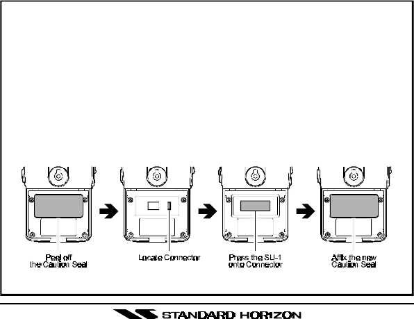
Installation of the SU-1
1. Make sure that the transceiver is off. Remove the hard or soft case, if
used. Remove the battery pack.
2. Locate the connector for the SU-1 under the caution seal in the battery
compartment on the back of the radio, just peel off the caution seal.
3. Align the connector on the SU-1 with the transceiver’s connector
and gently press the unit into place.
4. Affix the new (supplied with the SU-1) caution seal, and replace the
battery. Installation is now complete.
Figure 5

HX460S
Page 18
4.17 SETUP MODE
The HX460S’s Setup Mode allows a number of the HX460S operating pa-
rameters to be custom-configured for your operating requirements.
The Setup Mode is easy to activate and set, using the following procedure:
1. Turn the radio off.
2. Hold down the LAMP key, then turn on the transceiver while still holding
down the LAMP key.
3. “SET” will appear on the display, indicating that the Setup Mode has
been activated.
4. Press the LAMP key to select the Menu item to be adjusted.
5. Press the [p] or [q] key select the status or value of the Menu item.
6. After completing your adjustment, press the 16/9 key to save the new
setting and exit to normal operation.
4.17.1 bEP (KEY BEEP)
Function: Enable/Disable the Keypad beeper.
Available Values: ON/OFF
Default: ON
4.17.2 LP (LAMP MODE)
Function: Select the LCD/Keypad Lamp mode.
Available Values: KEY/TGL (Toggle)/5 (5 second)
Default: KEY
KEY:Illuminates the LCD/Keypad for 5 seconds when any key is
pressed.
TGL (Toggle):Pressing the LAMP key toggles the LCD/Keypad lamp On/
Off.
5 (5 second):Pressing the LAMP key illuminates the LCD/Keypad for 5 sec-
onds.
4.17.3 snL (SCAN LAMP)
Function: Enable/Disable the Scan lamp while scanning is paused.
Available Values: ON/OFF
Default: OFF
HX460S
Page 19
4.17.4 sCn (SCAN DISPLAY)
Function: Select the display mode while scanning.
Available Values: nor (Normal)/SPL (Special)
Default: nor (Normal)
nor (Normal):Changes the channel number accordance with scanning
SPL (Special):The channel number does not change during scanning. How-
ever, the channel number changes, when the scanner is
stopped, to indicate the channel number on which the radio
has received a transmission; this lets you see the last chan-
nel on which someone called.
4.17.5 bro (BAROMETRIC PRESSURE) [Requires optional SU-1]
Function: Select the unit of the Barometric Pressure display.
Available Values: HG (mm Hg)/HPA
Default: HG (mm Hg)
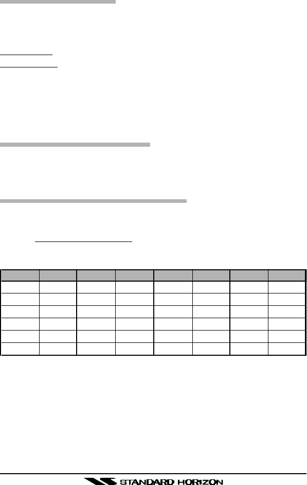
4.17.6 boF (BAROMETRIC PRESSURE OFFSET) [Requires optional SU-1]
Function: Calibrating the Barometric Pressure meter.
Press the [p] or [q] key to set the HX460S’s Barometric Pressure display to
match a Calibrated Barometer’s displayed pressure.
Barometric Pressure Conversion Chart
(Rounded to nearest whole number)
hpa Inches hpa Inches hpa Inches hpa Inches
982 29.0 1001 29.55 1011 29.85 1026 30.3
985 29.1 1002 29.6 1013 29.9 1029 30.4
989 29.2 1004 29.65 1014 29.95 1033 30.5
992 29.3 1006 29.7 1016 30.0 1036 30.6
996 29.4 1007 29.75 1019 30.1 – –
999 29.5 1009 29.8 1023 30.2 – –

HX460S
Page 20
4.18 CLONING
The HX460S includes a convenient “Clone” feature, which allows the memory
and configuration data from one transceiver to be transferred to another
HX460S. Here is the procedure for Cloning one radio’s data to another:
1. Turn both radios off.
2. Connect the (optional) CT-32 Clone Cable between the MIC/SP jacks of
the two transceivers.
3. Hold down the PRESET key and then turn on the transceiver. Do this for
both transceivers (the order of switching the radios on does not matter);
“
cLn
” will appear on the display on both transceivers.
4. On the Destination transceiver, press the MEM key (“
cr
” will appear on
the LCD).
5. Press the 16/9 key on the Source transceiver; “
cS
” will appear on the
Source radio, and the data will now be transferred.
6. If there is a problem during the cloning process, “
cE
” will displayed. Check
your cable connections and battery voltage, and try again.
7. If the data transfer is successful, the Destination transceiver will return
to normal operation; Turn both transceivers off and disconnect the Clone
cable. You can then turn the transceivers back on, and begin normal
operation.

HX460S
Page 21
4.19 RESETTING THE TRANSCEIVER’S MICROPROCESSOR
Resetting the microprocessor restores the initial, factory-supplied conditions
in the transceiver. These are called the “default” conditions. To reset the
microprocessor, first turn the transceiver off. Then, while pressing and hold-
ing in the WX and SCAN keys, turn the transceiver on. The default condi-
tions are:
•No channel numbers are in scan memory.
•Channel 16 is the priority channel.
•Channel 16 will be selected when the transceiver is turned on.
•WX channel 01 will be recalled when the WX key is pressed.
•Preset Channels are unassigned.
NOTE
The above procedure also resets the microprocessor. Perform this pro-
cedure if an operational problem occurs which cannot be solved by nor-
mal operating procedures.
HX460S
Page 22
5. BATTERY
The CNB460 is a high performance Lithium-Ion battery providing high ca-
pacity in a very compact package.
CAUTION
To avoid risk of explosion and injury, CNB460 battery pack should only
be removed, charged or recharged in non-hazardous environments.
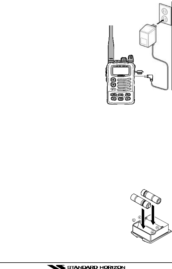
5.1 BATTERY CHARGING
If the radio has never been used, or its charge is depleted, it may be charged
by connecting the NC-72 battery charger, as shown in the illustration. If 12V
DC power is available, the optional E-DC-6 or the E-DC-19 DC adapter with
cigarette plug may be used for charging the battery. The NC-72, E-DC-6
and E-DC-19 will charge a completely discharged CNB460 battery pack in
about 3 hours.
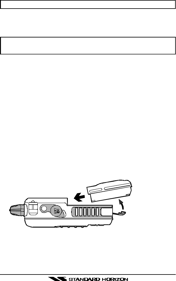
5.2 BATTERY REMOVAL/INSTALLATION
1. Turn the transceiver off.
2. To remove, open the Battery Pack Latch on the bottom of the trans-
ceiver, then slide the battery downward and out from the transceiver.
3. To install, insert the battery pack into the battery compartment on the
back of the transceiver, then close the Battery Pack Latch until it locks in
place with a “click.”
Close the Battery Pack Latch
Insert the Battery Pack
Figure 6
HX460S
5.3 USING THE NC-72 BATTERY CHARGER
1. Turn the transceiver off.
2. Insert the miniature plug on the end of
the NC-72 Battery Charger cable into the
EXT DC jack of the transceiver.
3. Plug the NC-72 into a 120 VAC wall out-
let.
4. The indicator on the radio will glow red,
indicating that charging has begun.
5. When charging is completed, the red
indicator on the radio will change to
green. Remove the plug from the EXT
DC jack when charging has been ac-
complished.
6. Replace the rubber gasket in its place
to protect the inside of the transceiver
from the water.
Caution: Make sure that the gasket is
in place to ensure the radio remains waterproof.
Note: The CNB460 battery pack must be installed in the radio prior to con-
nection of the NC-72 Battery Charger. If the NC-72 is plugged in before the
battery pack is installed, charging will not take place.
5.4 FBA-23 BATTERY CASE
FBA-23 is a battery case that holds two alkaline batteries and is used with the
HX460S transceiver. Alkaline batteries can be used for transmission in an
emergency, but power output will only be 1 Watt, and battery life will be short.
1. Slide the batteries into the FBA-23 with the Nega-
tive [–] side of the batteries touching the spring
connections inside the FBA-23.
2. Insert the FBA-23 into the battery compartment on
the back of the transceiver, then close the Battery
Pack Latch until it locks in place with a “click.”
Note: The battery indicator on the transceiver is only
applicable to the CNB460 rechargeable battery. Disre-
gard this indication when using alkaline batteries.
Page 23
Figure 7
Figure 8

HX460S
5.5 BATTERY SAFETY
Battery packs for your transceiver contain Lithium-Ion batteries. This type of
battery stores a charge powerful enough to be dangerous if misused or
abused, especially when removed from the transceiver. Please observe the
following precautions:
DO NOT SHORT BATTERY PACK TERMINALS
Shorting the terminals that power to the transceiver can cause sparks, se-
vere overheating, burns, and battery cell damage. If the short is of sufficient
duration, it is possible to melt battery components. Do not place a loose
battery pack on or near metal surfaces or objects such as paper clips, keys,
tools, etc. When the battery pack is installed on the transceiver, the termi-
nals that transfer current to the transceiver are not exposed.
DO NOT INCINERATE
Do not dispose of any battery in a fire or incinerator. The heat of fire may
cause battery cells to explode and/or release dangerous gases.
Page 24

HX460S
6. MAINTENANCE
For preventive maintenance and instructions on obtaining factory service,
please refer to the OWNER’S MANUAL SUPPLEMENT. For general trouble-
shooting, refer to this Troubleshooting Chart.
Page 25
TROUBLESHOOTING CHART
SYMPTON
The SCAN key
does not start the
scan.
The USA/INTL/
CAN modes do
not function.
Rotating the
SQUELCH
CONTROL knob
does not eliminate
background
noise.
Cannot change
any function.
Key Lock does
not function.
Indicator does not
light when
charging a
battery.
PROBABLE
CAUSE
No channels
memorized.
Squelch is not
adjusted.
Proper operation
not followed.
Low battery.
Key Lock is on.
Proper operation
not followed.
Defective battery
CNB460.
REMEDY
Use the MEM key to enter
desired channels into the
transceiver’s memory.
Adjust the squelch to
threshold or to the point
where noise just disappears.
Further adjustment of the
squelch control may elimi-
nate incoming signals.
HOLD down the 16/9 key
and press the WX key.
Charge battery. Refer to
section 5 of this manual.
Turn Key Lock off. Refer to
section 3.1. .
Hold down the LAMP key for
1 second.
Contact your Standard
Horizon dealer.

HX460S
7. SPECIFICATIONS
7.1 General
Frequency range:TX: 156.025 - 157.425 MHz
RX: 156.050 - 163.275 MHz
Number of channels:All US, Canadian & International channels
10 weather channels
Channel spacing:25 kHz
Modulation type:16K0G3E
Supply voltage:7.2 VDC
Current consumption:Standby: 50 mA
Saver on: 23 mA
RX: 195 mA
TX: 1.6 A (H)/0.9 A (M)/0.6 A (L)
Temperature range:–4 °F to +140 °F (–20 °C to +60 °C)
Battery life:11 hours @ 5 W (HI)
(STBY:RX:TX = 90:5:5) 15 hours @ 2.5W (MID)
19 hours @ 1 W (LOW)
Waterproof rating:30 minutes @ 1 meter depth (JIS 7)
Dimensions:3.8 (H) x 2.4 (W) x 1.1 (D) in
96 (H) x 60 (W) x 29 (D) mm
Weight:0.64 lb (290g)
7.2 Transmitter
Frequency range:156.025 - 157.425 MHz
RF output power:5 W/2.5 W/1 W @7.2 V or 13.8 V
Spurious emissions:At least 65 dB down
AF distortion:<5 % @1 kHz
Max deviation:±5 kHz
Frequency stability :±5 ppm
FM noise:>40 dB down
Microphone type:Condenser
Microphone impedance:2 kΩ
Page 26

HX460S
7.3 Receiver
Frequency range:156.050 - 163.275 MHz
Circuit type:Double-conversion superheterodyne
IFs:1st: 21.7 MHz
2nd: 450 kHz
Sensitivity:0.2 µV 12 dB SINAD
Adjacent channel selectivity:70 dB
Intermodulation response:70 dB
Spurious response rejection:70 dB
Speaker impedance:8 Ω
AF output:0.4 W @ 8 Ω 10 % THD (7.2V)
0.5 W @ 8 Ω 10 % THD (13.8V)

HX460S
MEMO

HX460S

HX460S
Copyright 2000
VERTEX STANDARD CO., LTD.
All rights reserved.
No portion of this manual
may be reproduced
without the permission of
VERTEX STANDARD CO., LTD.
Printed in Japan
Marine Division of VERTEX STANDARD
US Headquarters
17210 Edwards Rd., Cerritos, CA 90703, U.S.A.
0101T-DY
E
C
0
1
0
N
1
0
2