Yaesu Musen VX-150 Scanning Receiver User Manual VX150
Yaesu Musen Co., Ltd. Scanning Receiver VX150
UserManual.wiki
>
Yaesu Musen
>
VX 150 User Manual
users manual
Navigation menu
Upload a User Manual
Namespaces
Wiki Guide
HTML
PDF
Info
Views
User Manual
Discussion / Help
Navigation
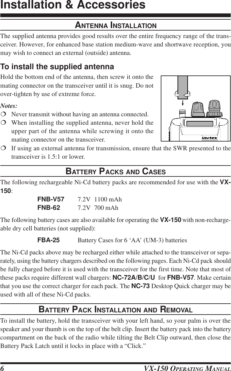
![VX-150 OPERATING MANUAL4FRONT PANELS•SpeakerThe internal speaker is located directly below the display.‚ MicThe internal microphone is located at the bottom right-hand corner of the speaker.ƒKeypadThese sixteen keys select the various operating features of the transceiver during re-ception, and generate DTMF (Dual Tone Multi Frequency) tone pairs during transmis-sion. One or two beeps will sound whenever one of the keys is pressed (if the beeper isactive). The labels on the faces of the keys indicate their primary functions, while thelabels above fifteen of the keys indicate alternate functions, which are activated bypressing the [F/W] key first, and then another key within five seconds. When referringto alternate key functions in this manual, we show the alternate key label followed bythe primary label in parentheses ( ). Primary key functions are referred to by the labelson the keyfaces.Remember to press the [F/W] key first (momentarily, unless otherwise indicated) whenyou want to use an alternate key function. All key functions are described in the “Op-eration” section, and summarized on the “VX-150 Operator’s Quick Reference Card.”Controls & Connectors](https://usermanual.wiki/Yaesu-Musen/VX-150/User-Guide-110534-Page-4.png)
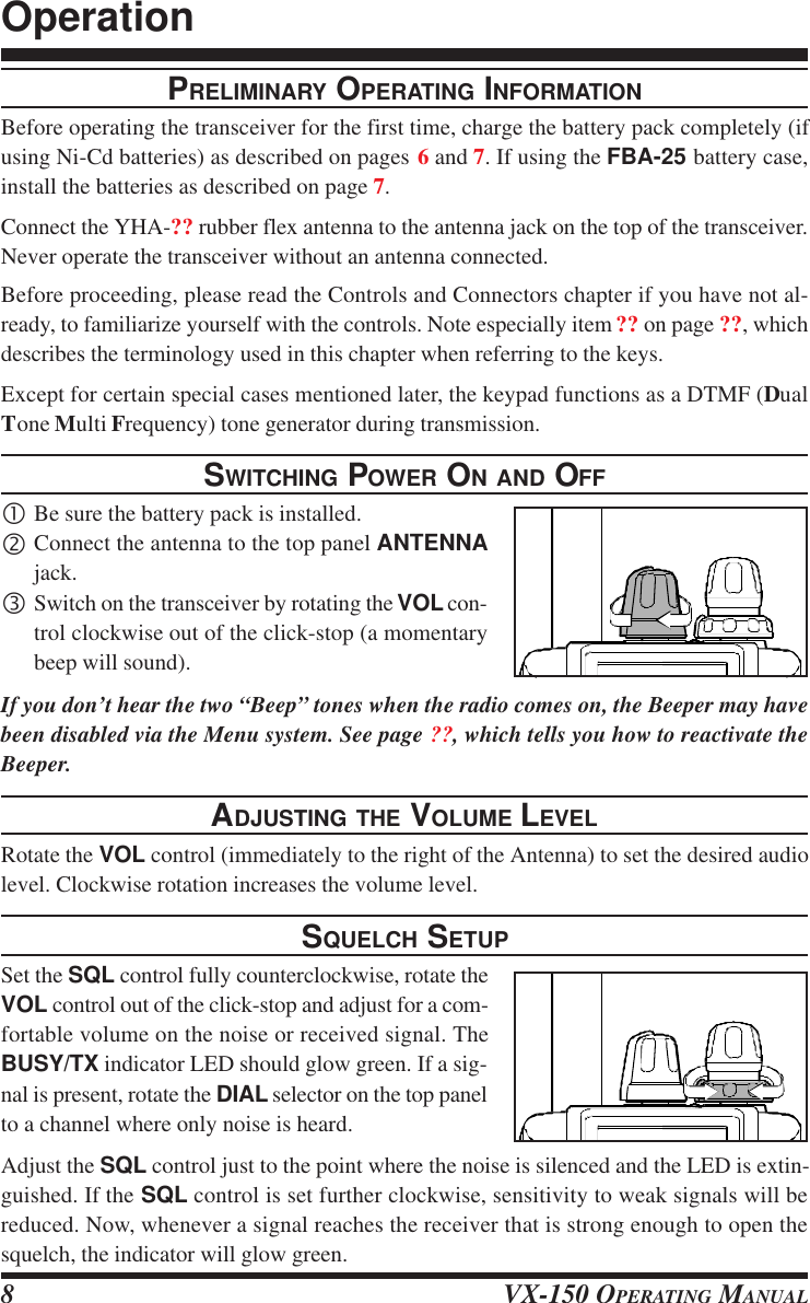
![VX-150 OPERATING MANUAL 7To remove the battery, turn the radio off and remove any protective cases. Open the Bat-tery Pack latch on the bottom of the radio, then slide the battery downward and out fromthe radio while unfolding the Belt Clip.Do not attempt to open any of the rechargeable Ni-Cd packs, as they could explode ifaccidentally short-circuited.If the battery has never beenused, or its charge is de-pleted, it may be charged byconnecting the NC-72A/B/C/F/U Battery Charger, asshown in the illustration, tothe EXT DC jack. If only 12~ 16 Volt DC power is avail-able, the optional E-DC-5B or E-DC-6 DC Adapter (with its cigarette lighter plug) mayalso be used for charging the battery, as shown in the illustration.INSTALLATION OF FBA-25 (Option) ALKALINE BATTERY CASEThe optional FBA-25 Battery Case allows receive monitoring using six “AA” size Alka-line batteries. Alkaline batteries can also be used for transmission in an emergency, butpower output will only be 300 mW, and battery life will be shortened dramatically.To Install Alkaline Batteries into the FBA-25rSlide the batteries into the FBA-25 as shown in the illustration, with the Negative [–]side of the batteries touching the spring connections inside the FBA-25.rUnlock the bottom plate by pushing the latch in the “Open” direction.rInstall the FBA-25 as shown in the illustration, with the [+] side facing the bottom ofthe transceiver.rRe-lock the bottom plate by carefully pressing the latch cover back into its normaloperating position.The FBA-25 does not provide connections for charging, since Alkaline cells cannot be re-charged. Therefore, the NC-72A/B/C/F/U, E-DC-5B, or E-DC-6 may safely be con-nected to the EXT DC jack when the FBA-25 is installed.Notes:mThe FBA-25 is designed for use only with AA-type Alkaline cells.mIf you do not use the VX-150 for a long time, remove the Alkaline batteries from theFBA-25, as battery leakage could cause damage to the FBA-25 and/or the trans-ceiver.Installation & Accessories](https://usermanual.wiki/Yaesu-Musen/VX-150/User-Guide-110534-Page-7.png)
![VX-150 OPERATING MANUAL 9Note that while receiving, one or more bargraph segments may appear along the bottom ofthe display, indicating signal strength on the receiving frequency. This indication is notaffected by the squelch setting, so even squelched signals may have some indication. If younotice more than one or two bargraph segments appearing while the squelch is still closed,try reducing the squelch control setting (if you want to hear weak signals).The Monitor switch on the USA versions (just above the PTT switch) allows you to checkfor channel activity beneath the squelch level and to adjust the volume without having toadjust the squelch: just press the Monitor switch and the squelch will open.FREQUENCY NAVIGATIONPress the [VFO(PRI)] button, if necessary, to select the VFO mode. The VX-150 has twovfos, labelled “A” and “B” either of which can be used for all of the procedures describedin this manual. You can change vfos with the [VFO(PRI)] button at any time.You have several ways to tune the VX-150: in selectable channel steps or 1 MHz stepswith the [s] / [t] keys or DIAL knob, and direct keypad frequency entry.Use the DIAL knob to tune the displayed VFO frequency at the current channel step rate.You can also press the [s] / [t] keys momentarily to do this, but if you press an [s] or[t] key for more than 1/2-second scanning will start. This is described later, so for now,just press an [s] / [t] key again to stop (if you have to).To change the MHz range of the VFO, you can press the [F/W] key followed by an [s] or[t] key (or turn the DIAL knob). Note the beeps when using the [s] / [t] keys: whenmoving up, and when moving down. When done press [F/W] again, or just wait five sec-onds.You can also enter a frequency directly just by keying in the 1 MHz and the kHz digits. Ifyou are using 5 or 10 kHz steps enter five digits. Otherwise just four digits will do. Partialentries can be cancelled with the [VFO(PRI)] key.Examples:To enter 146.5200 MHz, press à à à à To enter 146.5000 MHz, press à à à Operation](https://usermanual.wiki/Yaesu-Musen/VX-150/User-Guide-110534-Page-9.png)
![VX-150 OPERATING MANUAL10TRANSMITTINGWhen you wish to transmit, wait until the channel is clear (BUSY/TX lamp off), and squeezethe PTT switch. During transmission the BUSY/TX lamp glows red, and relative transmit-ter power output is indicated graphically along the bottom of the display. Release the PTTswitch to receive.If using a version B (in Europe), press the T-CALL switch (above the PTT switch) totransmit a 1750 Hz tone to access repeaters that require it.CHANGING THE CHANNEL STEPSTuning steps are factory preset to 20 kHz. To change a frequency step, follow the proce-dure below:•Press the [F/W] key, then immediately press the [0(SET)] key to enter the Set mode.‚Rotate the DIAL to select Menu Item #7 (“STEPSTEPSTEPSTEPSTEP”).ƒPress the [F/W] key to enable modification of the current setting.„Now rotate the DIAL knob to select 5, 10, 12.5, 15, 20, 25 or 50 kHz steps.…Press the PTT key to save the new setting and exit to normal operation.Operation](https://usermanual.wiki/Yaesu-Musen/VX-150/User-Guide-110534-Page-10.png)
![VX-150 OPERATING MANUAL 11KEYPAD/LCD ILLUMINATIONYour VX-150 includes a reddish illumination lamp which aids in nighttime operation. Thered illumination yields clear viewing of the display in a dark environment, with minimaldegradation of your night vision. Three options for activating the lamp are provided:KEYKEYKEYKEYKEY Mode: Pressing any key causes the lamp to provide illumination for 5 seconds,after which the lamp will automatically shut off.5SEC5SEC5SEC5SEC5SEC Mode: Pressing the LAMP switch momentarily causes the lamp to provide illu-mination for 5 seconds, after which the lamp will automatically shut off.TOGGLETOGGLETOGGLETOGGLETOGGLE Mode:Pressing the LAMP switch momentarily “Toggles” the lamp on and off.The lamp will stay illuminated until you press the LAMP switch oncemore.Here is the procedure for setting up the Lamp mode:•You first need to enter the “Set” (menu) mode. Press the [F/W] key, then immediatelypress the [0(SET)] key (just below the [F/W] key) to activate the Set mode.‚Now rotate the DIAL to select Menu Item #21 (“LMP MODELMP MODELMP MODELMP MODELMP MODE”).ƒPress the [F/W] key to enable modification of the current setting.„Next, rotate the DIAL to select one of the three modes described above.…When you have made your choice, press the PTT key to save the new setting for MenuItem #21. The transceiver will now return to normal operation.The 5SEC mode provides the greatest battery conservation, as it allows activation of thelamp only when you press the LAMP switch.If you press and hold in the LAMP key for one second, the lamp will remain illuminateduntil you press the LAMP switch once more (no time limit).Operation](https://usermanual.wiki/Yaesu-Musen/VX-150/User-Guide-110534-Page-11.png)
![VX-150 OPERATING MANUAL12REPEATER OPERATIONThe ARS (Automatic Repeater Shift) feature in the VX-150 provides repeater shift of thetransmit frequency whenever you are tuned to a standard repeater subband (see diagrambelow). When enabled, a small “–” or “+” displayed above the upper left-hand corner ofthe display that repeater shift is active, and closing the push-to-talk switch changes thedisplay to the (shifted) transmit frequency.Automatic Repeater Shift (ARS)The VX-150 provides a convenient Automatic Repeater Shift feature, which causes theappropriate repeater shift to be automatically applied whenever you tune into the desig-nated repeater sub-bands in your country. These sub-bands are shown below.If the ARS feature does not appear to be working, you may have accidentally disabled it.To re-enable ARS:•Press the [F/W] key, then immediately press the [0(SET)] key to enter the Set mode.‚Rotate the DIAL to select Menu Item #2 (“ARSARSARSARSARS”).ƒPress the [F/W] key to enable modification of the current setting.„Now rotate the DIAL to select “ON” (to enable Automatic Repeater Shift).…Press the PTT key to save the new setting and exit to normal operation.Manual Repeater Shift ActivationIf the ARS feature has been disabled, or if you need to set a repeater shift other than thatestablished by the ARS, you may set the direction of the repeater shift manually.To do this, press the [F/W] key, then press the [4(RPT)] key. This provides a “Shortcut” toMenu #3 (“RPTRPTRPTRPTRPT”). Rotate the DIAL, and you will see that the “–” or “+” icon appears at theupper of the LCD (when no icon is present, “Simplex” operation - transmit and receive onthe same frequency - has been selected, and the LCD will indicate “SIMPSIMPSIMPSIMPSIMP” in this case).When the desired shift direction has been selected, press the PTT key momentarily to saveyour new setting and exit.Advanced Operation](https://usermanual.wiki/Yaesu-Musen/VX-150/User-Guide-110534-Page-12.png)
![VX-150 OPERATING MANUAL 13Changing the Default Repeater ShiftsIf you travel to a different country, you may need to change the default repeater shift so asto ensure compatibility with local operating requirements.To do this, follow the procedure below:•Press the [F/W] key, then immediately press the [0(SET)] key to enter the Set mode.‚Rotate the DIAL to select Menu Item #3 (“RPTRPTRPTRPTRPT”).ƒPress the [F/W] key to enable modification of the current setting.„Now rotate the DIAL knob to select the new repeater shift magnitude.…Press the PTT key momentarily to save the new setting and exit.Checking the Repeater Uplink (Input) FrequencyIt often is helpful to be able to check the uplink (input) frequency of a repeater, to see if thecalling station is within direct (“Simplex”) range.To do this, just press the [REV(HM)] key momentarily. If Menu Item #20 (“REVREVREVREVREV/HMHMHMHMHM”) hasbeen set to “HMHMHMHMHM” you may press the [F/W] key, and then [REV(HM)] key. To return to thenormal uplink/downlink frequency relationship, repeat this step.Advanced Operation](https://usermanual.wiki/Yaesu-Musen/VX-150/User-Guide-110534-Page-13.png)
![VX-150 OPERATING MANUAL14CTCSS OPERATIONMany repeater systems require that a very-low-frequency audio tone be superimposed onyour FM carrier in order to activate the repeater. This helps prevent false activation of therepeater by radar or spurious signals from other transmitters. This tone system, called“CTCSS” (Continuous Tone Coded Squelch System), is included in your VX-150, and isvery easy to activate.CTCSS setup involves two actions: setting the Tone Frequency and then setting of theTone Mode. These actions are set up by using the [1(SQ TYP)] and [2(CODE)] keys, orMenu Items #25 and #26.•Press the [F/W] key, then immediately press the [1(SQ TYP)] key. This provides a“Short-cut” to Menu #25 (“SQL TYPSQL TYPSQL TYPSQL TYPSQL TYP”).‚Rotate the DIAL so that “TTTTT” appears on the display; this activates the CTCSS Encoder,which allows repeater access.ƒYou may notice an additional “DCSDCSDCSDCSDCS” icon appearing while you rotate the DIAL in thisstep. We’ll discuss the Digital Code Squelch system shortly.„Rotation of the DIAL in step ‚ above will occasionally cause “SQSQSQSQSQ” to appear adjacentto the “TTTTT” icon. When “TONE SQLTONE SQLTONE SQLTONE SQLTONE SQL” appears, this means that the Tone SQuelch systemis active, which mutes your VX-150’s receiver until it receives a call from anotherradio sending out a matching CTCSS tone. This can help keep your radio quiet until aspecific call is received, which may be helpful while operating in congested areas.…When you have made your selection of the CTCSS tone mode, press the PTT.†Press the [F/W] key, then immediately press the [2(CODE)] key. This provides a “Short-cut” to Menu #26 (“TN SETTN SETTN SETTN SETTN SET”).‡This Menu selection allows setting of the CTCSS tone frequency to be used.ˆRotate the DIAL until the display indicates the Tone Frequency you need to be using(ask the repeater owner/operator if you don’t know the tone frequency).‰Press the [F/W] key to save the new settings and exit to normal operation.CTCSS TONE FREQ UEN CY (Hz)67.0 69.3 71.9 74.4 77.0 79.7 82.5 85.488.5 91.5 94.8 97.4 100.0 103.5 107.2 110.9114.8 118.8 123.0 127.3 131.8 136.5 141.3 146.2151.4 156.7 162.2 167.9 173.8 179.9 186.2 192.8203.5 210.7 218.1 225.7 233.6 241.8 250.3 -Advanced Operation](https://usermanual.wiki/Yaesu-Musen/VX-150/User-Guide-110534-Page-14.png)
![VX-150 OPERATING MANUAL 15DCS OPERATIONAnother form of tone access control is Digital Code Squelch, or DCS. It is a newer, moreadvanced tone system which generally provides more immunity from false paging thandoes CTCSS. The DCS Encoder/Decoder is built into your VX-150, and operation is verysimilar to that just described for CTCSS. Your repeater system may be configured forDCS; if not, it is frequently quite useful in Simplex operation if your friend(s) use trans-ceivers equipped with this advanced feature.Just as in CTCSS operation, DCS requires that you set the Tone Mode to DCS and thatyou select a tone code.•Press the [F/W] key, then immediately press the [1(SQ TYP)] key. This provides a“Short-cut” to Menu #25 (“SQL TYPSQL TYPSQL TYPSQL TYPSQL TYP”).‚Rotate the DIAL until “DCSDCSDCSDCSDCS” appears on the display; this activates the DCS Encoder/Decoder.ƒWhen you have made your selection of the DCS mode, press the PTT.„Press the [F/W] key, then immediately press the [2(CODE)] key. This provides a “Short-cut” to Menu #26 (“TN SETTN SETTN SETTN SETTN SET”).…Rotate the DIAL to select the desired DCS Code (a three-digit number). Ask the re-peater owner/operator if you don’t know DCS Code; if you are working simplex, justset up the DCS Code to be the same as that used by your friend(s).†When you have made your selection, press the [F/W] key to save the new settings andexit to normal operation.Remember that the DCS is an Encode/Decode system, so your receiver will remain muteduntil a matching DCS code is received on an incoming transmission. Switch the DCS offwhen you’re just tuning around the band!Advanced OperationDCS CODE023 025 026 031 032 036 043 047 051 053 054 065 071 072 073 074 114 115 116122 125 131 132 134 143 145 152 155 156 162 165 172 174 205 212 223 225 226243 244 245 246 251 252 255 261 263 265 266 271 274 306 311 315 325 331 332343 346 351 356 364 365 371 411 412 413 423 431 432 445 446 452 454 455 462464 465 466 503 506 516 523 526 532 546 565 606 612 624 627 631 632 654 662664 703 712 723 731 732 734 743 754](https://usermanual.wiki/Yaesu-Musen/VX-150/User-Guide-110534-Page-15.png)
![VX-150 OPERATING MANUAL16TONE SEARCH SCANNINGIn operating situations where you don’t know the CTCSS or DCS tone being used byanother station or stations, you can command the radio to listen to the incoming signal andscan in search of the tone being used. Two things must be remembered in this regard:mYou must be sure that your repeater uses the same tone type (CTCSS vs. DCS).mSome repeaters do not pass the CTCSS tone; you may have to listen to the station(s)transmitting on the repeater uplink (input) frequency in order to allow Tone SearchScanning to work.To scan for the tone in use:•Set the radio up for either CTCSS or DCS Decoder operation (see the previous discus-sion). In the case of CTCSS, “T SQT SQT SQT SQT SQ” will appear on the display; in the case of DCS,“DCSDCSDCSDCSDCS” will appear on the display.‚Press the [F/W] key, then immediately press the [2(CODE)] key to select the “TNTNTNTNTNSETSETSETSETSET” Menu item (when TONE SQL is selected) or “DCS SETDCS SETDCS SETDCS SETDCS SET” (during DCS opera-tion).ƒPress and hold in the [s] or [t] key to start scanning for the incoming CTCSS or DCStone/code.„When the radio detects the correct tone or code, it will halt on that tone/code, and audiowill be allowed to pass. Press the [F/W] key to lock in that tone/code, and exit tonormal operation.If the Tone Scan feature does not detect a tone or code, it will continue to scan indefi-nitely. When this happens, it may be that the other station is not sending any tone. Youcan press the PTT switch to halt the scan at any time.You also can press the MONI key during Tone Scanning to listen to the (muted) signalfrom the other station. When you release the MONI key, Tone Scanning will resumeafter about a second.Tone Scanning works either in the VFO or Memory modes.Advanced Operation](https://usermanual.wiki/Yaesu-Musen/VX-150/User-Guide-110534-Page-16.png)
![VX-150 OPERATING MANUAL 17CTCSS/DCS BELL OPERATIONDuring CTCSS Decode or DCS operation, you may set the VX-150 up such that a ringing“Bell” sound alerts you to the fact that a call is coming in. Here is the procedure for activat-ing the Bell will ring in accordance with this programming.•Set the transceiver up for CTCSS Decode (“TONE SQL” or DCS operation, as de-scribed previously.‚Adjust the operating frequency to the desired channel.ƒPress the [F/W] key, then press the [0(SET)] key to activate the Set mode.„Rotate the DIAL to select Menu Item #18 (“BELLBELLBELLBELLBELL”).…Press the [F/W] key to enable adjustment of the Bell ringer.†Rotate the DIAL to set the desired number of rings of the Bell. The available choicesare 1, 3, 5, or 8 rings, REPEAT (continuous ringing), or OFF.‡Press the PTT key momentarily to save the new setting and exit to normal operation.When a station calls you whose transceiver is sending a CTCSS tone or DCS code whichmatches that set into your Decoder, the Bell will ring in accordance to this programming.TONE CALLING (1750 Hz)If the repeaters in your country require a 1750-Hz burst tone for access (typically in Eu-rope), you can set the MONI key to serve as a “TONE CALL” switch instead. To change theconfiguration of this switch, we again use the Menu to help us.•Press the [F/W] key, then press the [0(SET)] key to enter the Set mode.‚Rotate the DIAL to select Menu Item #19 (“MONMONMONMONMON/TCLTCLTCLTCLTCL”).ƒPress the [F/W] key to enable adjustment of this Menu item.„Rotate the DIAL to select “T.CALLT.CALLT.CALLT.CALLT.CALL” on the display.…Press the PTT key to save the new setting and exit.†To access a repeater, press and hold in the MONI key for the amount of time specifiedby the repeater owner/operator. The transmitter will automatically be activated, and a1750-Hz audio tone will be superimposed on the carrier. Once access to the repeaterhas been gained, you may release the MONI key, and use the PTT key for activating thetransmitter.Advanced Operation](https://usermanual.wiki/Yaesu-Musen/VX-150/User-Guide-110534-Page-17.png)
![VX-150 OPERATING MANUAL18CHANGING THE TRANSMITTER POWER LEVELYou can select between a total of three transmitter power levels on your VX-150. Theexact power output will vary somewhat, depending on the voltage supplied to the trans-ceiver. With the standard FNB-V57 Battery Pack, the power output levels available are:HIGHHIGHHIGHHIGHHIGH: ?? W MIDMIDMIDMIDMID: ?? W LOWLOWLOWLOWLOW: ?? WTo change the power level:•Press the [F/W] key, then immediately press the [3(LOW)] key.‚Now rotate the DIAL knob to select “LOWLOWLOWLOWLOW”, “MIDMIDMIDMIDMID” or “HIGHHIGHHIGHHIGHHIGH”.ƒPress the PTT key to save the new setting and exit to normal operation.TRANSMITTER TIME-OUT TIMER (TOT)The TOT feature provides a safety switch which limits transmission to a pre-programmedvalue. This will promote battery conservation by not allowing you to make excessively-long transmissions, and in the event of a stuck PTT switch (perhaps if the radio or a Speaker/Mic is wedged between car seats) it can prevent interference to other users as well asbattery depletion. As configured at the factory the TOT feature is set to OFF, and here isthe procedure for activating it:•Press the [F/W] key, then press the [0(SET)] key to enter the Set mode.‚Rotate the DIAL to select Menu Item #22 (“TOTTOTTOTTOTTOT”).ƒPress the [F/W] key to enable adjustment of this Menu item.„Rotate the DIAL to set the Time-Out Timer to the desired “Maximum TX” time (1minute, 2.5 minutes, 5 minutes, or 10 minutes).…Once you’ve made the selection you wish to use, press the PTT key to save the newsetting and exit to normal operation.Since brief transmissions are the mark of a good operator, try setting up your radio’sTOT feature for a maximum transmission time of 1 minute. This will significantly im-prove battery life, too!Advanced Operation](https://usermanual.wiki/Yaesu-Musen/VX-150/User-Guide-110534-Page-18.png)
![VX-150 OPERATING MANUAL 19RECEIVE BATTERY SAVER SETUPAn important feature of the VX-150 is its Receive Battery Saver, which “puts the radio tosleep” for a time interval, periodically “waking it up” to check for activity. If somebody istalking on the channel, the VX-150 will remain in the “active” mode, then resume its“sleep” cycles. This feature significantly reduces quiescent battery drain, and you maychange the amount of “sleep” time between activity checks using the Menu System:•Press the [F/W] key, then press the [0(SET)] key to enter the Set mode.‚Rotate the DIAL to select Menu Item #9 (“RX SAVERX SAVERX SAVERX SAVERX SAVE”).ƒPress the [F/W] key to enable adjustment of this Menu item.„Rotate the DIAL to select the desired “Sleep” duration. The selections available are200 ms, 300 ms, 500 ms, 1 second, and 2 seconds, or OFF. The default value is 200 ms.…When you have made your selection, press the PTT key to save the new setting and exitto normal operation.When you are operating on Packet, switch the Receive Battery Saver OFF, as the sleepcycle may “Collide” with the beginning of an incoming Packet transmission, causingyour TNC not to receive the full data burst.When the battery saving function is working, the beginning of the companion voicebreaks off and it is sometimes possible to hear it.TX BATTERY SAVERThe VX-150 also includes a useful Transmit Battery Saver, which will automatically lowerthe power output level when the last signal received was very strong. For example, whenyou are in the immediate vicinity of a repeater station, there generally is no reason to usethe full 5? Watts of power output in order to achieve full-quieting access to the repeater.With the Transmit Battery Saver, the automatic selection of Low Power operation con-serves battery drain significantly.To activate the Transmit Battery Saver:•Press the [F/W] key, then press the [0(SET)] key to enter the Set mode.‚Rotate the DIAL to select Menu Item #10 (“TX SAVETX SAVETX SAVETX SAVETX SAVE”).ƒPress the [F/W] key to enable adjustment of this Menu item.„Rotate the DIAL so as to select ON (thus activating the Transmit Battery Saver).…When you have completed your selection, press the PTT key to save the new settingand exit to normal operation.Advanced Operation](https://usermanual.wiki/Yaesu-Musen/VX-150/User-Guide-110534-Page-19.png)
![VX-150 OPERATING MANUAL20DISABLING THE BUSY/TX LEDFurther battery conservation may be accomplished by disabling the BUSY/TX LED. Usethe following procedure:•Press the [F/W] key, then press the [0(SET)] key to enter the Set mode.‚Rotate the DIAL to select Menu Item #12 (“BSY LEDBSY LEDBSY LEDBSY LEDBSY LED”).ƒPress the [F/W] key to enable adjustment of this Menu item.„Rotate the DIAL to set this Menu item to OFF (thus disabling the BUSY/TX LED).…Press the PTT key to save the new setting and exit to normal operation.BUSY CHANNEL LOCK-OUT (BCLO)The BCLO feature prevents the radio’s transmitter from being activated if a signal strongenough to break through the “Noise” squelch is present. On a frequency where stationsusing different CTCSS or DCS codes may be active, BCLO prevents you from disruptingtheir communications accidentally (because your radio may be muted by its own ToneDecoder). The default setting for the BCLO is OFF, and here is how to change that setting:•Press the [F/W] key, then press the [0(SET)] key to enter the Set mode.‚Rotate the DIAL to select Menu Item #23 (“BCLOBCLOBCLOBCLOBCLO”).ƒPress the [F/W] key to enable adjustment of this Menu item.„Rotate the DIAL to set the BCLO feature to the “ON” position.…Press the PTT key to save the new setting and resume normal operation.AUTOMATIC POWER-OFF (APO) FEATUREThe APO feature helps conserve battery life by automatically turning the radio off after auser-defined period of time within which there has been no dial or key activity. The avail-able selections for the time before power-off are 0.5/1/3/5/8 hours, as well as APO Off.The default condition for the APO is OFF , and here is the procedure for activating it:•Press the [F/W] key, then press the [0(SET)] key to enter the Set mode.‚Rotate the DIAL to select Menu Item #11 (“APOAPOAPOAPOAPO”).ƒRotate the DIAL to select the desired time period after which the radio will automati-cally shut down.„Once you have made your selection, press the PTT key to save the new setting and exitto normal operation.CHECKING THE BATTERY VOLTAGEThe VX-150’s measure the current battery voltage.•Press the [F/W] key, then press the [0(SET)]] key to enter the Set mode.‚Rotate the DIAL to select Menu Item #37 (“BATTBATTBATTBATTBATT”).ƒPress the [F/W] key to check the battery condition.„To return to normal operation, press the [F/W] key, then press the PTT.Advanced Operation](https://usermanual.wiki/Yaesu-Musen/VX-150/User-Guide-110534-Page-20.png)
![VX-150 OPERATING MANUAL 21KEYBOARD LOCKINGIn order to prevent accidental frequency change or inadvertent transmission, various as-pects of the VX-150’s keys and switches may be locked out. The possible lockout combi-nations are:KEYKEYKEYKEYKEY: Just the front panel keys are locked outDIALDIALDIALDIALDIAL: Just the top panel DIAL is locked outKEYKEYKEYKEYKEY + DIALDIALDIALDIALDIAL: Both the DIAL and Keys are locked outPTTPTTPTTPTTPTT: The PTT switch is locked (TX not possible)KEYKEYKEYKEYKEY + PTTPTTPTTPTTPTT: Both the keys and PTT switch are locked outDIALDIALDIALDIALDIAL + PTTPTTPTTPTTPTT: Both the DIAL and PTT switch are locked outALLALLALLALLALL: All of the above are locked outTo lock out some or all of the keys:•Press the [F/W] key, then press the [0(SET)] key to enter the Set mode.‚Rotate the DIAL to select Menu Item #32 (“LK MODELK MODELK MODELK MODELK MODE”).ƒPress the [F/W] key to enable setting of the Lock mode (which defines which keys/functions are to be locked out).„Rotate the DIAL to choose between one of the locking schemes as outlined above.…Once you have made your selection, press the PTT key momentarily to save the newsetting and resume normal operation.†To activate the locking feature, press the [F/W] key, then press the [6(LOCK)] key.The “??” icon will lower on the LCD. To cancel keyboard locking, again press [F/W]key, followed by [6(LOCK)] key.DISABLING THE KEYPAD BEEPERIf the keypad’s Beeper creates an inconvenience (particularly when operating in a quietroom), it may easily be disabled.•Press the [F/W] key, then press the [0(SET)] key to enter the Set mode.‚Rotate the DIAL to select Menu Item #16 (“KEY BPKEY BPKEY BPKEY BPKEY BP”).ƒPress the [F/W] key to enable adjustment of this Menu item.„Rotate the DIAL to change the setting from ON to OFF.…When you have made your selection, press the PTT key to save the new setting and exitto normal operation.†If you wish to re-enable the Beeper, just repeat the above procedure, rotating the DIALto select ON in step ‚ above.Advanced Operation](https://usermanual.wiki/Yaesu-Musen/VX-150/User-Guide-110534-Page-21.png)
![VX-150 OPERATING MANUAL22DTMF OPERATIONThe VX-150’s 16-button keypad allows easy DTMF dialing for Autopatch or repeatercontrol purposes. Besides numerical digits [0] through [9], the keypad includes the [ÛÛÛÛÛ]and [#] digits, plus the [A], [B], [C], and [D] tones often used for repeater control.Manual DTMF Tone GenerationYou can generate DTMF tones during transmission manually.•Press the PTT switch to begin transmission.‚While transmitting, press the desired numbers on the keypad.ƒWhen you have sent all the digits desired, release the PTT key.DTMF AutodialerNine DTMF Autodial memories are provided, allowing you to store telephone numbersfor autopatch use. You can also store short autopatch access code streams so as to avoidhaving to send them manually.Here is the DTMF Autodial storage procedure:•Press the [F/W] key, then press the [0(SET)] key to enter the Set mode.‚Rotate the DIAL to select Menu Item #28 (“DTMFDTMFDTMFDTMFDTMF”).ƒPress the [F/W] key to enable adjustment of this Menu item.„Rotate the DIAL to select the DTMF Memory register into which you wish to store thisDTMF string.…Press the [F/W] key, then press the [F/W] key to begin DTMF Memory entry into theselected register.†Rotate the DIAL to select the first digit of the desired label. When you have made yourselection, press the [s] key momentarily to move to the next digit.‡Repeat the previous step to program the remaining letters , numbers of the desiredlabel. A total of 16 digits may be used in the creation of a label.ˆPress the PTT switch to save the setting. To store other numbers, repeat this process,using a different DTMF memory register.To send the telephone number:•Press [F/W], then the [9(DTMF)] key to activate the DTMF Autodialer function.‚Press the PTT switch to begin transmission.ƒPress the numerical key ([1] through [9]) corresponding to the DTMF memory stringyou wish to send. Once the string begins, you may release the PTT key, as the transmit-ter will be held “on the air” until the DTMF string is completed.Advanced Operation](https://usermanual.wiki/Yaesu-Musen/VX-150/User-Guide-110534-Page-22.png)
![VX-150 OPERATING MANUAL 23DTMF CODE SQUELCH (REQUIRES OPTIONAL FVP-25)The code squelch system use 3-digit numeric codes (000000000000000 ~ 999999999999999), transmitted as DTMF(dual, audible) tone pairs.There are twelve code memories numbered [1] ~ [9], [A] and [D], which store 3-digitDTMF paging codes (these are independent and unrelated to the channel memories and theVFOs).The code squelch mode is very simple: both you and the other station communicate usingthe same 3-digit DTMF sequence, sent automatically at the start of every transmission.Your receiver normally remains silent to all signals that are not prefixed by your selected3-digit code. When you receive the matching tone sequence, your squelch opens and staysopen until a few seconds after the end of their transmission.In the code squelch mode, you must first store and then manually select the one CodeMemory holding the 3-digit DTMF code required to open your squelch (as described onthe following pages). Also, in the code squelch mode, Code Memories [1] ~ [9] alwaysfunction the same.Codes of up to nine other stations can be stored in these memories. These are stations youexpect to frequently contact, and whose page calls you also want to receive. Members of acommon group or club usually share a common 3-digit paging code so that they can bepaged simultaneously.Remember, with Code Squelch operation (but not with DTMF Paging), you can only re-ceive a call on the currently selected Code Memory, and the display does not change whena call is received. So for code squelch, as mentioned before, the Code Memory distinctiondoes not apply (although you must still store the 3-digit Code Memories).Storing Code MemoriesThe first thing to do before using Code Squelch is to store 3-digit code in Code Memory:•Press the [F/W] key, then press the [0(SET)] key to enter the Set mode.‚Rotate the DIAL to select Menu Item #40 (“PG CODEPG CODEPG CODEPG CODEPG CODE”).ƒPress the [F/W] key to enable adjustment of this Menu item.„Rotate the DIAL to select the Code Memories register into which you wish to store thiscode string.…Press the [F/W] key, then press the [F/W] key to begin Code Memories entry into theselected register.†Rotate the DIAL to select Key in the DTMF digits you wish to store into this register.‡Press the PTT switch to save the setting. To store other numbers, repeat this process,using a different DTMF memory register.Advanced Operation](https://usermanual.wiki/Yaesu-Musen/VX-150/User-Guide-110534-Page-23.png)
![VX-150 OPERATING MANUAL24You can use the same procedure to store the Memory Codes of other individuals or groupsin Code Memories [1] ~ [9].Although up to nine Code Memories can be stored, you might only need a few of them tocall your friends or a specific group. Likewise, you’ll probably only want your radio torespond to pages directed to you (or maybe your group or club’s code). The followingexplains how to temporarily inhibit unused Code Memories.Page Code InhibitDuring the Code Memory storage procedure above, when storing Code Memories [1] ~[9], you have an opportunity to decide whether your transceiver should respond to incom-ing paging calls on a particular Memory Code.To activate Code setting:•Press the [F/W] key, then press the [0(SET)] key, to enter the Set mode.‚Rotate the DIAL to select Menu #40 (“PG CODEPG CODEPG CODEPG CODEPG CODE”).ƒPress the [F/W] key, then rotate the DIAL to select the Code Memories register intowhich you wish to this code string.„Press the [F/W] key, rotate the DIAL to set the function ON.…When you have made your selection, press the PTT key to save the new setting and exitto Set mode.DTMF Code Squelch OperationAs described earlier, with DTMF code squelch activated (CODE displayed), your squelchwill not open until you receive the proper 3-digit DTMF code according to the selectedcode memory. Likewise, each time you press the PTT, the same 3-digit code is automati-cally sent to open the other station’s DTMF coded squelch.With the Code Squelch activated in this manner, you will hear three DTMF code digitstransmitted when you press your PTT switch. These are the digits stored in the CodeMemory currently selected, and they will open the squelch of the other station.Therefore, at the start of each transmission, you must wait a second or two after pressingthe PTT switch for the DTMF code to be sent (you will hear it in your speaker).When you finish your conversation, if you need to reactivate DTMF Code Paging, pressCODE (PAGE) until PAGE is again displayed.Advanced Operation](https://usermanual.wiki/Yaesu-Musen/VX-150/User-Guide-110534-Page-24.png)
![VX-150 OPERATING MANUAL 25PAGING TX DELAYWhen calling other stations using Code Squelch, particularly through repeaters, you mayfind that some stations are unable to receive your calls. This can be caused by their receiversquelch not opening fast enough (after receiving your transmitted carrier) to allow all ofthe DTMF digits to be received and decoded. To correct this problem, you can set a longerdelay (750 ms) between the time your transmitter is keyed and the time the first DTMFdigit is sent.•Press the [F/W] key, then press the [0(SET)] key to enter the Set mode.‚Rotate the DIAL to select Menu Item #35 (“DT DLYDT DLYDT DLYDT DLYDT DLY”).ƒPress the [F/W] key to enable adjustment of this Menu item.„Rotate the DIAL to change the setting from 450 to 750.…When you have made your selection, press the PTT key to save the new setting and exitto normal operation.PAGING “ANSWER BACK”When you press the PTT to respond to a page call, the caller’s ID code, followed by aDTMF “ÛÛÛÛÛ” and your personal ID code, are transmitted.This informs the calling station that their page was received. If you prefer, you can have theVX-150 respond to page calls automatically (transpond).As mentioned before, the answer-back mode acknowledges a received page by “pagingback” the calling station (just as if you manually selected their 3-digit code and pressed thePTT).To activate Paging Answer back:•Press the [F/W] key, then press the [0(SET)] key, to enter the Set mode.‚Rotate the DIAL to select Menu #41 (“PG ASBKPG ASBKPG ASBKPG ASBKPG ASBK”).ƒPress the [F/W] key to enable adjustment of this Menu item.„Rotate the DIAL to set the function ON.…When you have made your selection, press the PTT key to save the new setting and exitto normal operation.Advanced Operation](https://usermanual.wiki/Yaesu-Musen/VX-150/User-Guide-110534-Page-25.png)
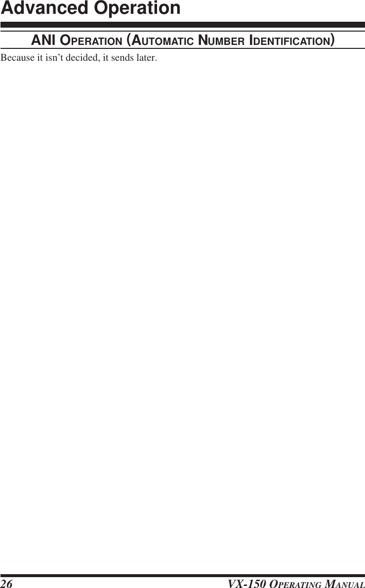
![VX-150 OPERATING MANUAL 27ARTS (AUTOMATIC RANGE TRANSPONDER SYSTEM)The ARTS feature uses DCS signaling to inform both parties when you and another ARTS-equipped station are within communications range. This may be particularly useful duringSearch-and Rescue situations, where is important to stay in contact with other members ofyour group.Both stations must set up their DCS codes to the same code number, then activate theirARTS feature using the command appropriate for their radio. Alert ringers may be acti-vated, if desired.Whenever you push the PTT, or every 25 (or 15) sec-onds after ARTS is activated, your radio will transmita signal which includes a (subaudible) DCS signal forabout 1 second. If the other radio is in range, the beeperwill sound (if enabled) and the display will show “INININININRNGRNGRNGRNGRNG” as opposed to the out of range display “OUTOUTOUTOUTOUTRNGRNGRNGRNGRNG” in which ARTS operation begins.Whether you talk or not, the polling every 15 or 25 seconds will continue until you de-activate ARTS. Every 10 minutes, moreover, you can have your radio transmit your callsignvia CW, so as to comply with identification requirements. When ARTS is de-activated,DCS will also be deactivated (if you were not using it previously in non-ARTS operation).If you move out of range for more than one minute (four pollings), your radio will sensethat no signal has been received, three beeps will sound, and the display will revert to“OUT RNGOUT RNGOUT RNGOUT RNGOUT RNG.” If you move back into range, your radio will again beep, and the display willchange back to the “IN RNGIN RNGIN RNGIN RNGIN RNG” indication.You must terminate ARTS in order to resume normal operation. This is a safety featuredesigned to prevent accidental loss of contact due to channel change, etc.Here is how to activate ARTS:Basic ARTS Setup and Operation•Set your radio and the other radio(s) to the same DCS code number, per the discussionon page ??.‚Press [F/W], then press the [7(P1)] key to activate the ARTS operation.ƒPress the [F/W] key. You will observe the “OUT RNGOUT RNGOUT RNGOUT RNGOUT RNG” display on the LCD. ARTSoperation has now commenced.„Every 15 seconds, your radio will transmit a “polling” call to the other station. When thatstation responds with its own ARTS polling signal, the display will change to “IN RNGIN RNGIN RNGIN RNGIN RNG” toconfirm that the other station “polling” code was received in response to yours.…Press the [F/W] key again to exit ARTS operation and resume normal functioning ofthe transceiver.Advanced Operation](https://usermanual.wiki/Yaesu-Musen/VX-150/User-Guide-110534-Page-27.png)
![VX-150 OPERATING MANUAL28ARTS Polling Time OptionsThe ARTS feature may be programmed to poll every 15 seconds (default value) or 25seconds. The default value provides maximum battery conservation, because the pollingsignal is sent out less frequently. To change the polling interval:•Press the [F/W] key, then press the [0(SET)] key, to enter the Set mode.‚Rotate the DIAL to select Menu #15 (“AR ITVLAR ITVLAR ITVLAR ITVLAR ITVL”).ƒPress the [F/W] key to enable changing of this Menu item.„Rotate the DIAL to select the desired polling interval (15 or 25 seconds).…When you have made your selection, press the PTT key to save the new setting and exitto normal operation.ARTS Alert Beep OptionsThe ARTS feature allows two kinds of alert beeps (with the additional option of turningthem off), so as to alert you to the current status of ARTS operation. Depending on yourlocation and the potential annoyance associated with frequent beeps, you may choose theBeep mode which best suits your needs. The choices are:IN RANGE: The beeps are issued only when the radio first confirms that you are withinrange, but does not re-confirm with beeps thereafter.ALWAYS: Every time a polling transmission is received from the other station, the alertbeeps will be heard.ARB OFF: No alert beeps will be heard; you must look at the display to confirm currentARTS status.To set the ARTS Beep mode, use the following procedure:•Press the [F/W] key, then press the [0(SET)] key, to enter the Set mode.‚Rotate the DIAL to select Menu #14 (“ARTS BPARTS BPARTS BPARTS BPARTS BP”).ƒPress the [F/W] key to enable changing of this Menu item.„Rotate the DIAL to select the desired ARTS Beep mode (see above).…When you have made your selection, press the PTT key to save the new setting and exitto normal operation.Advanced Operation](https://usermanual.wiki/Yaesu-Musen/VX-150/User-Guide-110534-Page-28.png)
![VX-150 OPERATING MANUAL 29CW Identifier SetupThe ARTS feature includes a CW identifier, as discussed previously. Every ten minutesduring ARTS operation, the radio can be instructed to send “DE (your callsign) K” if thisfeature is enabled. The callsign field may contain up to 16 characters.Here’s how to program the CW Identifier:•Press the [F/W] key, then press the [0(SET)] key, to enter the Set mode.‚Rotate the DIAL to select Menu #29 (“CW IDCW IDCW IDCW IDCW ID”).ƒPress the [F/W] key to enable changing of this Menu item.„Press the [F/W] key, then press the [F/W] key, to begin entry of the letters and numbersin your callsign.…Rotate the DIAL to select the first letter or number in your callsign. When the correctcharacter has been selected, press the [s] key to move on to the next character.†Repeat step 5 as many times as necessary to complete your callsign, pressing [F/W]between each entry. Note that the “slant bar” (– • • – •) is among the available charac-ters, should you be a “portable” station.‡When you have entered your entire callsign, press the [F/W] key.ˆWhen you have entered your entire callsign, press the PTT key. to save the settings andexit to normal operation.Note that the “DE” (– • • •) preceding your callsign is already programmed; you onlyneed to program your callsign, and the “DE” will be appended at the time of transmis-sion.To activate CW identifier:•Press the [F/W] key, then press the [0(SET)] key, to enter the Set mode.‚Rotate the DIAL to select Menu #29 (“CW IDCW IDCW IDCW IDCW ID”).ƒPress the [F/W] key to enable changing of this Menu item.„Rotate the DIAL to set the CW ID function ON.…When you have made your selection, press the PTT key to save the new setting and exitto normal operation.Advanced Operation](https://usermanual.wiki/Yaesu-Musen/VX-150/User-Guide-110534-Page-29.png)
![VX-150 OPERATING MANUAL30The VX-150 provides a wide variety of memory system resources. These include:m199 “Standard” memory channels, numbered “11111” through “199199199199199.”mA Home channel per band, allowing storage and quick recall of one prime frequencyon each band.mTen sets of band-edge memories also known as “Programming Memory Scan” chan-nels, labeled “L1L1L1L1L1/U1U1U1U1U1” through “L5L5L5L5L5/U5U5U5U5U5”MEMORY STORAGE•Select the desired frequency, while operating in the VFO mode. Be sure to set up anydesired CTCSS or DCS tones, as well as any desired repeater offset. The power levelmay also be set at this time, if you wish to store it.‚Press and hold the [F/W] key for one second.ƒWithin five seconds of releasing the [F/W] key, rotate the DIAL to select the desiredmemory channel.„Press the [F/W] key once more to store the frequency into memory.…You still will be operating in the “VFO” mode, so you may now enter other frequen-cies, and store them into additional memory locations, by repeating the above process.STORING INDEPENDENT TRANSMIT FREQUENCIES (“ODD SPLITS”)All memories can store an independent transmit frequency, for operation on repeaters withnon-standard shift. To do this:•Store the receive frequency using the method already described under MEMORY STOR-AGE (it doesn’t matter if a repeater offset is active).‚Turn to the desired transmit frequency, then press and hold the [F/W] key for one second.ƒWith in five seconds of releasing the [F/W] key, rotate the DIAL to select the samememory channel number as used in step • above.„Press and hold the PTT switch then press the [F/W] key once more momentarily (thisdoes not key the transmitter).Whenever you recall a memory which contains independently-stored transmit and re-ceive frequencies, the “[+][–]” indication will appear in the display.MEMORY RECALL•While operating in the VFO mode, press the [MR(SKIP)] key. The “MRMRMRMRMR” indicatorwill show that you are now in the Memory Recall mode.‚Rotate the DIAL to select the desired channel.ƒTo return to the VFO mode, press the [VFO(PRI)] key.An easy way to recall memories is to key in the memory channel number, then press[MR(SKIP)].For example, to recall memory channel #16, press [1]-[6]-[MR(SKIP)].Memory Mode](https://usermanual.wiki/Yaesu-Musen/VX-150/User-Guide-110534-Page-30.png)
![VX-150 OPERATING MANUAL 31HOME CHANNEL MEMORYA special one-touch “HOME” channel is available to allow quick recall of a favorite oper-ating frequency. Memory storage is simple to accomplish:•Set Menu Item #20 (“REVREVREVREVREV/HMHMHMHMHM”) to “HOMEHOMEHOMEHOMEHOME” if it is not already set to that option (seepage ??).‚Select the desired frequency, while operating in the VFO mode. Be sure to set up anydesired CTCSS or DCS tones, as well as any desired repeater offset. The power levelmay also be set at this time, if you like.ƒPress and hold the [F/W] key for 1/2 second.„While the memory channel number is blinking, just press the [REV(HM)] key. Thefrequency and other data (if any) will now be stored in the special HOME channelregister.…To recall the HOME channel, press the [REV(HM)] key momentarily while operatingin the VFO or MR mode.LABELING MEMORIESYou may wish to append an alpha-numeric “Tag” (label) to a memory or memories, to aidin recollection of the channel’s use (such as a club name, etc.). This is easily accomplishedusing the Set mode.•Recall the memory channel on which you wish to append a label.‚Press the [F/W] key, then press the [0(SET)] key, to enter the Menu mode.ƒRotate the DIAL to select Menu #1 (“NAMENAMENAMENAMENAME”).„Press the [F/W] key to enable changing of this Menu item.…Press the [F/W] key, then press the [F/W] key, to begin entry of the Label.†Rotate the DIAL to select the first digit of the desired label. When you have made yourselection, press the[s] key momentarily to move to the next character.‡Repeat the previous step to program the remaining letters , numbers, or symbols of thedesired label. A total of seven characters may be used in the creation of a label.ˆWhen you have completed the creation of the label, press the [F/W] key, then press thePTT to save the label and exit.To activate alphanumeric Tag:•Press the [F/W] key, then press the [0(SET)] key, to enter the Set mode.‚Rotate the DIAL to select Menu #1 (“NAMENAMENAMENAMENAME”).ƒPress the [F/W] key to enable changing of this Menu item.„Rotate the DIAL to set the “ALPHAALPHAALPHAALPHAALPHA”.…When you have made your selection, press the PTT key to save the new setting and exitto normal operation.Memory Mode](https://usermanual.wiki/Yaesu-Musen/VX-150/User-Guide-110534-Page-31.png)
![VX-150 OPERATING MANUAL32MEMORY OFFSET TUNINGOnce you have recalled a particular memory channel, you may easily tune off that channel,as though you were in the “VFO” mode.•With the VX-150 in the “MRMRMRMRMR” (Memory Recall) mode, select the desired memorychannel.‚Now press the [MR(SKIP)] key momentarily. The “MRMRMRMRMR” indicator will be blinking.ƒRotate the DIAL, as desired, to tune to a new frequency. The synthesizer steps selectedfor VFO operation on the current band will be the steps used during Memory Tuning.„If you wish to return to the original memory frequency, press the [MR(SKIP)] keymomentarily. The “MRMRMRMRMR” indication.…If you wish to store a new frequency set during Memory Tuning, just press and hold inthe [F/W] key for 1/2 second, per normal memory storage procedure. The micropro-cessor will automatically set itself to the next-available clear memory location, and youthen press [F/W] again to lock in the new frequency.If you want to replace the original memory contents with those of the new frequency, besure to rotate the DIAL to the original memory channel number!Any required CTCSS/DCS changes, or repeater offset modifications, must be done be-fore storing the data into the new (or original) memory channel location.MASKING MEMORIESThere may be situations where you want to “Mask” memories so they are not visible duringmemory selection or scanning. For example, several memories used only in a city you visitinfrequently may be stored, then “Masked” until you visit that city, at which time you can“Unmask” them for normal use.•Press the [MR(SKIP)] key, if needed, to enter the MR mode.‚Press and hold in the [F/W] key for one second, then rotate the DIAL to select thememory channel to be “Masked” from view.ƒPress the [MR(SKIP)] key. The display will revert to memory channel #1. If you rotatethe DIAL to the location you just “Masked,” you will observe that it is now invisible.„To Unmask the hidden memory, repeat the above procedure: press and hold in the [F/W] key for one second, rotate the DIAL to select the masked memory’s number, thenpress [MR(SKIP)] to restore the memory channel’s data.Memory Mode](https://usermanual.wiki/Yaesu-Musen/VX-150/User-Guide-110534-Page-32.png)
![VX-150 OPERATING MANUAL 33Memory Only ModeThis allows operation only on stored memories, which are displayed by name (if any) at theright, and the memory channel number to the left. No frequency is displayed, and only“CH.nnCH.nnCH.nnCH.nnCH.nn” appear if you haven’t assigned name to a memory.Repeater shift and tone setting indicators are displayed, although they cannot be changed.•Turn the radio off.‚Press and hold the [PTT] and [LAMP] key while turning the radio on.ƒRotate the DIAL to select “MEM.ONLYMEM.ONLYMEM.ONLYMEM.ONLYMEM.ONLY”.„Press the [F/W] key momentarily to initialize the radio.…Repeat the previous step, it returns to normal operation.Memory Mode](https://usermanual.wiki/Yaesu-Musen/VX-150/User-Guide-110534-Page-33.png)
![VX-150 OPERATING MANUAL34The VX-150 allows you to scan just the memory channels, the operating band, or a portionof that band. It will halt on signals encountered, so you can talk to the station(s) on thatfrequency, if you like.Scanning operation is basically the same in each of the above modes. Before you begin,take a moment to select the way in which you would like the scanner to resume scanningafter it halts on a signal.Setting the Scan Resume TechniqueThree options for the Scan-Resume mode are available:5 SEC5 SEC5 SEC5 SEC5 SEC: In this mode, the scanner will halt on a signal it encounters, and will hold there for5 seconds. If you do not take action to disable the scanner within that time period,the scanner will resume even if the stations are still active.BUSYBUSYBUSYBUSYBUSY: In this mode, the scanner will halt on a signal it encounters. Two seconds after thecarrier has dropped because the other station(s) ceased transmission, the scannerwill resume. In the case of constant-carrier signals like Weather Station broad-casts, the scanner will likely remain on this frequency indefinitely.HOLDHOLDHOLDHOLDHOLD: In this mode, the scanner will halt on a signal it encounters. It will not restartautomatically; you must manually re-initiate scanning if you wish to resume.To set the Scan-Resume mode•Press the [F/W] key, then press the [0(SET)] key, to enter the Set mode.‚Rotate the DIAL to select Menu #7 (“RESUMERESUMERESUMERESUMERESUME”).ƒPress the [F/W] key to enable changing of this Menu item.„Rotate the DIAL to select the desired scan-resume mode.…When you have made your selection, press the PTT key to save the new setting and exitto normal operation.The default condition for this Menu Item is “5 SEC”.Scanning](https://usermanual.wiki/Yaesu-Musen/VX-150/User-Guide-110534-Page-34.png)
![VX-150 OPERATING MANUAL 35VFO SCANNINGThis mode allows you to scan the entire current operating band.•Select the VFO mode by pressing the [VFO(PRI)] key, if necessary.‚Press and hold in the [s] or [t] key for one second to start scanning.ƒIf and when the scanner encounters a signal strong enough to open the squelch, thescanner will halt temporarily; the decimal point of the frequency display will blinkduring this “Pause” condition.„The scanner will then resume according to the Scan Resume selected in the previoussection.…To cancel scanning, press the PTT, [MR(SKIP)], or [VFO(PRI)] key.When you press the [sssss] key to start scanning, the VX-150 will be changing frequencyin the upward direction. If you want to change direction of the scan while it is under-way, rotate the DIAL one click in the opposite direction (in this case, one click counter-clockwise). You’ll see the scanner turn around and change frequency downward!MEMORY SCANNINGMemory scanning is similarly easy to initiate:•Set the radio to the Memory mode by pressing the [MR(SKIP)] key, if necessary.‚Press and hold in the [s] / [t] key for one second to initiate scanning.ƒAs with VFO scanning, the scanner will halt on any signal encountered that is strongenough to open the squelch; it will then resume scanning according to the Scan-Re-sume mode set previously.„To cancel scanning, press the PTT, [MR(SKIP)], or [VFO(PRI)] key.HOW TO SKIP (OMIT) A CHANNEL DURING MEMORY SCAN OPERATIONWhen you have some very active channels stored in memories, you may wish to skip themwhen scanning, but still have them available for manual selection.Such channels may be “Skipped” during scanning, if you like:•Set the radio to the Memory Mode by pressing the [MR(SKIP)] key, if necessary.‚Rotate the DIAL to select the Memory Channel to be skipped during scanning.ƒPress the [F/W] key momentarily (not for 1/2 second), then press the [MR(SKIP)] key(momentarily). A small “SKIP” will appear to the LCD. indicating it is to be ignoredduring scanning.To re-institute the channel into the scanning loop, repeat the above three steps (the “Skipped”channel will, of course, still be accessible via manual channel selection methods using theDIAL in the MR mode).Scanning](https://usermanual.wiki/Yaesu-Musen/VX-150/User-Guide-110534-Page-35.png)
![VX-150 OPERATING MANUAL36PROGRAMMABLE (BAND LIMIT) MEMORY SCAN (PMS)This feature allows you to set sub-band limits for either scanning or manual VFO opera-tion. For example, you might wish to set up a limit (in North America) of 144.300 MHz to148.000 MHz so as to prevent encroachment into the SSB/CW “Weak Signal” portion ofthe band below 144.300 MHz. Here’s how to do this:•Set the radio to the VFO mode by pressing the [VFO(PRI)] key, if necessary.‚Using the techniques learned earlier, store (per the above example) 144.300 MHz intoMemory Channel #L1L1L1L1L1 (the “LLLLL” designates the Lower sub-band limit).ƒLikewise, store 148.000 MHz into Memory Channel #U1U1U1U1U1 (the “UUUUU” designates the Up-per sub-band limit).„Switch to the Memory mode by pressing the [MR(SKIP)] key once, then rotate theDIAL to select Memory Channel # L1L1L1L1L1.…Press the [MR(SKIP)] key; the “MRMRMRMRMR” label will be blinking in the left-hand frequencyof the display.†You may now rotate the DIAL, or begin scanning by pressing the [s] or [t] key forone second. The transceiver will behave as though it is in the standard VFO mode, butoperation will be restricted to the range between Memory Channels L1L1L1L1L1 and U1U1U1U1U1.If you wish to scan, do not press the [MR(SKIP)] key, as it is disabled during PMSoperation. Press and hold in the [VFO(PRI)] key instead.‡Five pairs of Band Limit memories, labeled L1L1L1L1L1/U1U1U1U1U1 through L5L5L5L5L5/U5U5U5U5U5 are available.PRIORITY CHANNEL SCANNING (DUAL WATCH)The VX-150 scanning features include a two-channel scanning capability which allowsyou to operate on a VFO or Memory channel, while periodically checking a user-select-able Priority Channel for activity. If a station is received on the Priority Channel which isstrong enough to open the Squelch, the scanner will pause on that station in accordancewith the Scan-Resume mode set via Menu #7 (see page ??).Here is the procedure for activating Priority Channel Dual Watch operation:•Recall the memory channel you wish to be the “Priority” Channel.‚Set the radio to the VFO mode by pressing the [VFO(PRI)] key.ƒPress the [F/W] key momentarily (not for 1/2 second), then press the [VFO(PRI)] key(momentarily). A small “PRI” will appear to the LCD.Here is the procedure for activating Two-VFO Dual Watch operation:•Press the [VFO(PRI)] key to switch to the VFO mode, if needed.‚Press the [F/W] key, then press and hold in the [VFO(PRI)] key.The VX-150 will now periodically change from the VFO-A frequency to the VFO-Bfrequency, checking for activity on VFO-B for 0.2 second.Scanning](https://usermanual.wiki/Yaesu-Musen/VX-150/User-Guide-110534-Page-36.png)
![VX-150 OPERATING MANUAL 37AUTOMATIC LAMP ILLUMINATION ON SCAN STOPThe VX-150 will automatically illuminate the LCD Lamp whenever the scanner stops on asignal; this allows you to see the frequency of the incoming signal better at night. Note thatthis will, of course, increase the battery consumption, so be sure to switch it off during theday (the default condition for this feature is “ON”.The procedure for disabling the Scan Lamp is:•Press the [F/W] key, then press the [0(SET)] key, to enter the Set mode.‚Rotate the DIAL to select Menu #8 (“SCN LMPSCN LMPSCN LMPSCN LMPSCN LMP”).ƒPress the [F/W] key to enable changing of this Menu item.„Rotate the DIAL to set this Menu item to OFF.…When you have made your selection, press the PTT key to save the new setting and exitto normal operation.BAND EDGE BEEPERThe VX-150 will automatically “beep” when a band edge is encountered during scanning(either in standard VFO scanning or during PMS operation). You may disable this feature,if it is annoying, without disabling the keypad beeper (the default condition for this featureis “ON”.The procedure for disabling the Band-Edge Beeper is:•Press the [F/W] key, then press the [0(SET)] key, to enter the Set mode.‚Rotate the DIAL to select Menu #17 (“EDGE BPEDGE BPEDGE BPEDGE BPEDGE BP”).ƒPress the [F/W] key to enable changing of this Menu item.„Rotate the DIAL to set this Menu item to OFF.…When you have made your selection, press the PTT key to save the new setting and exitto normal operation.PROGRAMMING THE KEY FUNCTIONSDefault VX-150 set mode have been assigned (at the factory) to the [7(P1)] and [8(P2)]keys. These may be changed by the user, if you wish to define another set mode for a keys.To change the assignment of a key’s set mode:•Press the [F/W] key, then press the [0(SET)] key, to enter the Set mode.‚Rotate the DIAL knob to the menu to be assigned a function.ƒPress and hold in the [F/W] key for 1.5 second.„Press the [7(P1)] or [8(P2)] key to the new setting and exit to set mode.Scanning](https://usermanual.wiki/Yaesu-Musen/VX-150/User-Guide-110534-Page-37.png)
![VX-150 OPERATING MANUAL38The Smart Search feature allows you to load frequencies automatically according to whereactivity is encountered by your radio. When Smart Search is engaged, the transceiver willsearch above and below your current frequency, storing active frequencies as it goes (with-out stopping on them even momentarily); these frequencies are stored into a special SmartSearch memory bank, consisting of 31 memories (15 above the current frequency, 15 be-low the current frequency, plus the current frequency itself).Two basic operating modes for Smart Search are available:SINGLESINGLESINGLESINGLESINGLE: In this mode, the transceiver will sweep the current band once in each direc-tion starting on the current frequency. All channels where activity is presentwill be loaded into the Smart Search memories; whether or not all 31 memo-ries are filled, the search will stop after one sweep in each direction.CONTINUECONTINUECONTINUECONTINUECONTINUE: In this mode, the transceiver will make one pass in each direction as withOne-Shot searching; if all 31 channels are not filled after the first sweep,however, the radio will continue sweeping until they are all filled.Setting the Smart Search Mode•Press the [F/W] key, then press the [0(SET)] key, to enter the Set mode.‚Rotate the DIAL to select Menu #31 (“SMT MODSMT MODSMT MODSMT MODSMT MOD”).ƒPress the [F/W] key to enable changing of this Menu item.„Rotate the DIAL to select the desired Smart Search mode (see above).…When you have made your selection, press the PTT key to save the new setting and exitto normal operation.Storing Smart Search Memories•Set the radio to the VFO mode.‚Press the [F/W] key, then press the [8(P2)] key.ƒPress the [s] or [t] key to begin the Smart Search scanning.„As active channels are detected, you will observe the number of “loaded” channelsincreasing in the regular memory channel window.…Depending on the mode you set for Smart Search operation (SINGLE or CONTINUE),the Smart Search scan will eventually terminate, and the LCD will revert to SmartSearch Memory Channel 0.†To recall Smart Search memories, rotate the DIAL to choose from among the SmartSearch memories.‡To return to normal operation, Press the [VFO(PRI)] key.Smart Search is a great tool when visiting a city for the first time. You don’t need tospend hours looking up repeater frequencies from a reference guidebook... just askyour VX-150 where the action is!Smart Search Operation](https://usermanual.wiki/Yaesu-Musen/VX-150/User-Guide-110534-Page-38.png)
![VX-150 OPERATING MANUAL40MICROPROCESSOR RESETTING•Turn the radio off.‚Press and hold the [PTT] and [LAMP] key while turning the radio on.ƒRotate the DIAL to select “ALL.RSTALL.RSTALL.RSTALL.RSTALL.RST”.„Press the [F/W] key momentarily to initialize the radio.SET MODE RESETTING•Turn the radio off.‚Press and hold the [PTT] and [LAMP] key while turning the radio on.ƒRotate the DIAL to select “SET.RSTSET.RSTSET.RSTSET.RSTSET.RST”.„Press the [F/W] key momentarily to initialize the Set mode.Reset](https://usermanual.wiki/Yaesu-Musen/VX-150/User-Guide-110534-Page-40.png)
![VX-150 OPERATING MANUAL 41The VX-150 includes a convenient “Clone” feature, which allows the memory and con-figuration data from one transceiver to be transferred to another VX-150. This can beparticularly useful when configuring a number of transceivers for a public service opera-tion. Here is the procedure for Cloning one radio’s data to another:•Turn both radios off.‚Connect the optional CT-27 cloning cable between the MIC/EAR jacks of the tworadios.ƒPress and hold the [PTT] and [LAMP] key while turning the radio on.„Rotate the DIAL to select “CLONECLONECLONECLONECLONE”.…Press the [F/W] key, to enter the CLONE mode. “CLONECLONECLONECLONECLONE” will appear on the displaysof both radios when the Clone mode is successfully activated in this step.†On the Destination radio, press the [MONI] key (“SAVINGSAVINGSAVINGSAVINGSAVING” will appear on the LCD).‡Press the [PTT] key on the Source radio; “SENDINGSENDINGSENDINGSENDINGSENDING” will appear on the Source radio,and the data is transferred.ˆIf there is a problem during the cloning process, “C-ERRORC-ERRORC-ERRORC-ERRORC-ERROR” will be displayed. Checkyour cable connections and battery voltage, and try again.‰If the data transfer is successful, the Destination radio will return to normal operation;Turn both radios off and disconnect the CT-27. You can then turn the radios back on,and begin normal operation.Cloning](https://usermanual.wiki/Yaesu-Musen/VX-150/User-Guide-110534-Page-41.png)
![VX-150 OPERATING MANUAL42Default–ONSIMP0.6MHzOFF?5SECON200msOFFOFFON–INRANGE25 SECONOFFOFF•¦REVKEYOFFOFFONOFF100 Hz023–––SINGLEKEYWIDE50 msThe VX-150 Set (Menu) mode is easy to activate and set. Use the following procedure:•Press the [F/W] key, then press the [0(SET)] key, to activate the Set mode.‚Turn the DIAL to select the Menu item number to be adjusted.ƒPress the [F/W] key momentarily, then rotate the DIAL to adjust or select the parameterto be changed on the Menu item selected in above step.„After completing your selection and adjustment, press the PTT switch momentarily toexit the Set mode and exit to normal operation.Set Mode SummaryMenu ItemNAMEARSRPTSHIFTV-SPLITSTEPRESUMESCN LMPRX SAVETX SAVEAPOBSY LEDARTSARTS BPAR ITVLKEY BPEDGE BPBEELMON/TCLREV/HMLMP MODTOTBCLOCLK SFTSQL TYPTN SETDCS SETDTMFCW IDS SRCHSMT MODLK MODENAR/WIDDTMF SPFunctionStore Alpha-Numeric “Tags”Enable/disable the Automatic Repeater ShiftSet the Repeater Shift DirectionSet the magnitude of the Repeater ShiftEnable/disable “VFO Split” OperationSetting of the synthesizer stepsSelect the Scan Resume modeEnable/disable the Scan lampSelect the Rx-mode Battery Saver intervalEnable/disable the Transmit Battery SaverSet the Automatic Power-Off timeEnable/disable the BUSY LEDActivate the ARTS operationSelect the Beep option during ARTS operationSelect the Polling Interval during ARTS opera-tionEnable/disable the Keypad beeperEnable/disable the Band-edge beeperSelect the CTCSS Bell ringer repetitionsSelect the MON key functionSelect the function of [REV(HC)] keySelect the LCD/Keypad Lamp modeSet the TOT timeEnable/disable the Busy Channel Lock-out fea-tureShifting of the CPU clock frequencySelect the Tone Encoder and/or Decoder modeSetting of the CTCSS Tone FrequencySetting of the DCS codeProgramming the DTMF AutodialerProgramming and activate the CW IderActivate the Smart SearchSelect the Smart Search Sweep modeSelect the Control Locking lockout combinationSelect the Operating modeSelect the DTMF Autodialer sending speedAvailable Values–ON/OFF-RPT/SIMP/+RPT0 - 99.9MHzON/OFF5/10/12.5/15/20/25/50 kHz5SEC/BUSY/HOLDON/OFFOFF/200ms/300ms/500ms/1s/2sON/OFFOFF/30min/1h/3h/5h/8hON/OFF–OFF/INRANGE/ALWAYS15 SEC/25 SECON/OFFON/OFFOFF/1/3/5/8/REPEATMON/T-CALLREV/HOMEKEY/5SEC/TOGGLEOFF/1min/2.5min/5min/10minON/OFFON/OFFOFF/TONE/TONESQL/DCS39 Standard CTCSS tones104 standard DCS codes–––SINGLE/CONTINUEKEY/DIAL/KEY+DIAL/PTT/KEY+PTT/DIAL+PTT/ALLNARROW/WIDE50 ms/100 msSet ModeItem #12345678910111213141516171819202122232425262728293031323334](https://usermanual.wiki/Yaesu-Musen/VX-150/User-Guide-110534-Page-42.png)
![VX-150 OPERATING MANUAL 43Item #3536373839404142Menu ItemDT DIYANIBATTSKIPPAG MODPG CODEPG ASBKSCRMBLEFunctionSelect the DTMF Autodialer delay timeProgram and activate the ANI IdentifierIndication of the Supply VoltageEnable/Disable skipping of a memory duringscanningStoring Code MemoriesEnable/disable The Pager Answer BackEnable/disable The ScramblerAvailable Values450 ms/750 ms––ON/OFF–ON/OFFON/OFFDefault450 ms––OFF–OFFOFFSet Mode DetailsSet Item 1 [NAME]Function: Store Alpha-Numeric “Tags” for the Memory channels.See page ?? for details.Set Item 2 [ARS]Function: Enable/disable the Automatic Repeater Shift function.Available Values: ON/OFFDefault: ONSet Item 3 [RPT]Function: Set the Repeater Shift DirectionAvailable Values: -RPT/SIMP/+RPTDefault: SIMPSet Item 4 [SHIFT]Function: Set the magnitude of the Repeater Shift.Available Values: 0.00 ~ 99.9 MHzDefault: Depends on the transceiver version, as well as the setting of Menu #2 (ARS).Set Item 5 [V-SPLIT]Function: Enable/disable “VFO Split” OperationAvailable Values: ON/OFFDefault: OFFSet Item 6 [STEP]Function: Setting of the synthesizer steps.Available Values: 5/10/12.5/15/20/25/50 kHzDefault: Depends on the transceiver version.•¦Depends on the transceiver versionSet Mode](https://usermanual.wiki/Yaesu-Musen/VX-150/User-Guide-110534-Page-43.png)
![VX-150 OPERATING MANUAL44Set Item 7 [RESUME]Function: Select the Scan Resume mode.Available Values: 5 SEC/BUSY/HOLDDefault: 5 SECSet Item 8 [SCN LMP]Function: Enable/disable the Scan lamp while paused.Available Values: ON/OFFDefault: ONSet Item 9 [RX SAVE]Function: Select the Receive-mode Battery Saver interval (“Sleep” ratio).Available Values: OFF/200ms(1:1)/300ms(1:1.5)/500ms(1:2.5)/1s(1:5)/2s(1:10)Default: 200ms(1:1)Set Item 10 [TX SAVE]Function: Enable/disable The Transmit Battery Saver.Available Values: ON/OFFDefault: OFFSet Item 11 [APO]Function: Set the Automatic Power-Off time.Available Values: OFF/30 min/1 hour/3 hour/5 hour/8 hourDefault: OFFSet Item 12 [BSY LED]Function: Enable/disable the BUSY LED while the Squelch is open.Available Values: ON/OFFDefault: ONSet Item 13 [ARTS]Function: Activate the ARTS.See page ?? for details.Set Item 14 [ARTS BP]Function: Select the Beep option during ARTS operation.Available Values: OFF/INRANGE/ALWAYSDefault: INRANGESet Item 15 [AR ITVL]Function: Select the Polling Interval during ARTS operation.Available Values: 15 SEC/25 SECDefault: 25 SECSet Mode](https://usermanual.wiki/Yaesu-Musen/VX-150/User-Guide-110534-Page-44.png)
![VX-150 OPERATING MANUAL 45Set Item 16 [KEY BP]Function: Enable/disable the Keypad beeper.Available Values: ON/OFFDefault: ONSet Item 17 [EDGE BP]Function: Enable/disable the Band-edge beeper while scanning.Available Values: ON/OFFDefault: OFFSet Item 18 [BELL]Function: Select the CTCSS Bell ringer repetitions.Available Values: OFF/1/3/5/8/REPEATDefault: OFFSet Item 19 [MON/TCL]Function: Select the MONI key (just below the PTT switch) function.Available Values: MONI/T-CALLDefault: Depends on the transceiver version.MONI: Pressing the [MONI] key causes the noise/tone Squelch to be over-ridden, al-lowing you to listen for weak (or non-encoded) signals.T.CALL: Pressing the [MONI] key activates a 1750-Hz burst tone, used for repeater ac-cess in many countries.Set Item 20 [REV/HM]Function: Select the function of the [REV(HM)] key.Available Values: REV/HOMEDefault: REVSet Item 21 [LMP MOD]Function: Select the LCD/Keypad Lamp mode.Available Values: KEY/5SEC/TOGGLEDefault: KEYSet Item 22 [TOT]Function: Set the TOT time.Available Values: OFF/1 min/2.5 min/5 min/10 minDefault: OFFSet Mode](https://usermanual.wiki/Yaesu-Musen/VX-150/User-Guide-110534-Page-45.png)
![VX-150 OPERATING MANUAL46Set Item 23 [BCLO]Function: Enable/disable the Busy Channel Lock-Out feature.Available Values: ON/OFFDefault: OFFSet Item 24 [CLK SFT]Function: Shifting of CPU clock frequency.Available Values: ON/OFFDefault: OFFThis function is only used to move a spurious response “birdie” should it fall on a desiredfrequency.Set Item 25 [SQL TYP]Function: Select the Tone Encoder and/or Decoder mode.Available Values: OFF/T/TSQ/DCSDefault: OFFT: CTCSS EncoderTSQ: CTCSS Encoder/DecoderDCS: Digital Coded Squelch Encoder/DecoderSet Item 26 [TN SET]Function: Setting of the CTCSS Tone FrequencyAvailable Values: 39 standard CTCSS tonesDefault: 100 HzIn this mode, press the [F/W] key, then press the [PTT] key, to save the new setting andexit to normal operation.Set Item 27 [DCS SET]Function: Setting of the DCS code.Available Values: 104 standard DCS codes.Default: 023In this mode, press the [F/W] key, then press the [PTT] key, to save the new setting andexit to normal operation.Set Item 28 [DTMF]Function: Programming the DTMF Autodialer.See page ?? for details.Set Mode](https://usermanual.wiki/Yaesu-Musen/VX-150/User-Guide-110534-Page-46.png)
![VX-150 OPERATING MANUAL 47Set Item 29 [CW ID]Function: Program and activate the CW Identifier (used during ARTS operation).See page ?? for details.Set Item 30 [S SRCH]Function: Activate the Smart Search.See page ?? for details.Set Item 31 [SMT MOD]Function: Select the Smart Search Sweep mode.Available Values: SINGLE/CONTDefault: SINGLESINGLE:The transceiver sweeps the current band once in each direction starting on thecurrent frequency. All channels where activity is present (up to 15 in each direc-tion) are loaded into the Smart Search memories. Whether or not all 31 memo-ries are filled, the search stops after one sweep in each direction.CONT: The transceiver makes a sweep in each direction as with the “SINGLE” mode,but if all 31 channels are not filled after the first sweep, the radio continuessweeping until they are all filled.Set Item 32 [LK MODE]Function: Select the Control Locking lockout combination.Available Values: KEY/DIAL/ KEY+DIAL/PTT/KEY+PTT/DIAL+PTT/ALLDefault: KEYSet Item 33 [NAR/WID]Function: Select the Operating mode.Available Values: NARROW/WIDEDefault: WIDESet Item 34 [DTMF SP]Function: Select the DTMF Autodialer sending speed.Available Values: 50 ms/100 msDefault: 50 ms (High speed)Set Item 35 [DT DLY]Function: Select the DTMF Autodialer delay time.Available Values: 450 ms/750 msDefault: 450 msSet Mode](https://usermanual.wiki/Yaesu-Musen/VX-150/User-Guide-110534-Page-47.png)
![VX-150 OPERATING MANUAL48Set Item 36 [ANI]Function: Program and activate the ANI IdentifierSee page ?? for details.Set Item 37 [BATT]Function: Indication of the Supply Voltage.In this mode, press the [F/W] key, then press the [PTT] key, to exit to normal operation.Set Item 38 [SKIP]Function: Enable/disable skipping of a memory during scanning.Available Values: ON/OFFDefault: OFF (Scanner stops when the channel is busy)Set Item 39 [PAG MOD] (requires optional FVP-25)Function:See page ?? for details.Set Item 40 [PG CODE] (requires optional FVP-25)Function: Storing Code MemoriesSee page ?? for details.Set Item 41 [PG ASBK] (requires optional FVP-25)Function: Enable/disable The Pager Answer BackAvailable Values: ON/OFFDefault: OFFSet Item 42 [SCRMBLE] (requires optional FVP-25)Function: Enable/disable The ScramblerAvailable Values: ON/OFFDefault: OFFSet Mode](https://usermanual.wiki/Yaesu-Musen/VX-150/User-Guide-110534-Page-48.png)